

Page 1
Accessories
AS-Interface
(AS-i)
Inverter Drives 8400 motec
_ _ _ _ _ _ _ _ _ _ _ _ _ _ _ _ _ _
E84DGFCAxxx
Communication Manual EN
Ä.MLxä
13444387
L
Page 2

Contents
_ _ _ _ _ _ _ _ _ _ _ _ _ _ _ _ _ _ _ _ _ _ _ _ _ _ _ _ _ _ _ _ _ _ _ _ _ _ _ _ _ _ _ _ _ _ _ _ _ _ _ _ _ _ _ _ _ _ _ _ _ _ _ _
1 About this documentation _ _ _ _ _ _ _ _ _ _ _ _ _ _ _ _ _ _ _ _ _ _ _ _ _ _ _ _ _ _ _ _ _ _ _ _ _ _ _ 4
1.1 Document history _ _ _ _ _ _ _ _ _ _ _ _ _ _ _ _ _ _ _ _ _ _ _ _ _ _ _ _ _ _ _ _ _ _ _ _ _ _ _ _ _ _ _ _ 6
1.2 Conventions used _ _ _ _ _ _ _ _ _ _ _ _ _ _ _ _ _ _ _ _ _ _ _ _ _ _ _ _ _ _ _ _ _ _ _ _ _ _ _ _ _ _ _ _ 7
1.3 Terminology used _ _ _ _ _ _ _ _ _ _ _ _ _ _ _ _ _ _ _ _ _ _ _ _ _ _ _ _ _ _ _ _ _ _ _ _ _ _ _ _ _ _ _ _ 8
1.4 Notes used _ _ _ _ _ _ _ _ _ _ _ _ _ _ _ _ _ _ _ _ _ _ _ _ _ _ _ _ _ _ _ _ _ _ _ _ _ _ _ _ _ _ _ _ _ _ _ _ 9
2Safety instructions _ _ _ _ _ _ _ _ _ _ _ _ _ _ _ _ _ _ _ _ _ _ _ _ _ _ _ _ _ _ _ _ _ _ _ _ _ _ _ _ _ _ _ _ 10
2.1 General safety and application notes _ _ _ _ _ _ _ _ _ _ _ _ _ _ _ _ _ _ _ _ _ _ _ _ _ _ _ _ _ _ _ _ _ 10
2.2 Device and application-specific safety instructions _ _ _ _ _ _ _ _ _ _ _ _ _ _ _ _ _ _ _ _ _ _ _ _ _ _ 11
2.3 Residual hazards _ _ _ _ _ _ _ _ _ _ _ _ _ _ _ _ _ _ _ _ _ _ _ _ _ _ _ _ _ _ _ _ _ _ _ _ _ _ _ _ _ _ _ _ _ 11
3 Product description _ _ _ _ _ _ _ _ _ _ _ _ _ _ _ _ _ _ _ _ _ _ _ _ _ _ _ _ _ _ _ _ _ _ _ _ _ _ _ _ _ _ _ 12
3.1 Application as directed _ _ _ _ _ _ _ _ _ _ _ _ _ _ _ _ _ _ _ _ _ _ _ _ _ _ _ _ _ _ _ _ _ _ _ _ _ _ _ _ _ 12
3.2 Features and variants _ _ _ _ _ _ _ _ _ _ _ _ _ _ _ _ _ _ _ _ _ _ _ _ _ _ _ _ _ _ _ _ _ _ _ _ _ _ _ _ _ _ 13
3.3 Connections and interfaces _ _ _ _ _ _ _ _ _ _ _ _ _ _ _ _ _ _ _ _ _ _ _ _ _ _ _ _ _ _ _ _ _ _ _ _ _ _ _ 14
4 Technical data _ _ _ _ _ _ _ _ _ _ _ _ _ _ _ _ _ _ _ _ _ _ _ _ _ _ _ _ _ _ _ _ _ _ _ _ _ _ _ _ _ _ _ _ _ _ 16
4.1 General data and operating conditions _ _ _ _ _ _ _ _ _ _ _ _ _ _ _ _ _ _ _ _ _ _ _ _ _ _ _ _ _ _ _ _ 16
4.2 Protocol data _ _ _ _ _ _ _ _ _ _ _ _ _ _ _ _ _ _ _ _ _ _ _ _ _ _ _ _ _ _ _ _ _ _ _ _ _ _ _ _ _ _ _ _ _ _ _ 17
4.3 Communication time _ _ _ _ _ _ _ _ _ _ _ _ _ _ _ _ _ _ _ _ _ _ _ _ _ _ _ _ _ _ _ _ _ _ _ _ _ _ _ _ _ _ 18
5Installation _ _ _ _ _ _ _ _ _ _ _ _ _ _ _ _ _ _ _ _ _ _ _ _ _ _ _ _ _ _ _ _ _ _ _ _ _ _ _ _ _ _ _ _ _ _ _ _ 19
5.1 Mechanical installation _ _ _ _ _ _ _ _ _ _ _ _ _ _ _ _ _ _ _ _ _ _ _ _ _ _ _ _ _ _ _ _ _ _ _ _ _ _ _ _ _ 20
5.2 Electrical installation _ _ _ _ _ _ _ _ _ _ _ _ _ _ _ _ _ _ _ _ _ _ _ _ _ _ _ _ _ _ _ _ _ _ _ _ _ _ _ _ _ _ 21
5.2.1 Bus cable specification _ _ _ _ _ _ _ _ _ _ _ _ _ _ _ _ _ _ _ _ _ _ _ _ _ _ _ _ _ _ _ _ _ _ _ _ _ 21
5.2.2 AS-i connection _ _ _ _ _ _ _ _ _ _ _ _ _ _ _ _ _ _ _ _ _ _ _ _ _ _ _ _ _ _ _ _ _ _ _ _ _ _ _ _ _ 22
5.2.3 Voltage supply _ _ _ _ _ _ _ _ _ _ _ _ _ _ _ _ _ _ _ _ _ _ _ _ _ _ _ _ _ _ _ _ _ _ _ _ _ _ _ _ _ 23
6 Commissioning _ _ _ _ _ _ _ _ _ _ _ _ _ _ _ _ _ _ _ _ _ _ _ _ _ _ _ _ _ _ _ _ _ _ _ _ _ _ _ _ _ _ _ _ _ 24
6.1 Before initial switch-on _ _ _ _ _ _ _ _ _ _ _ _ _ _ _ _ _ _ _ _ _ _ _ _ _ _ _ _ _ _ _ _ _ _ _ _ _ _ _ _ _ 24
6.2 How to configure the host (master) _ _ _ _ _ _ _ _ _ _ _ _ _ _ _ _ _ _ _ _ _ _ _ _ _ _ _ _ _ _ _ _ _ _ 25
6.3 Settings for AS-i communication in the »Engineer« _ _ _ _ _ _ _ _ _ _ _ _ _ _ _ _ _ _ _ _ _ _ _ _ _ _ 26
6.3.1 Addressing the AS-i slaves _ _ _ _ _ _ _ _ _ _ _ _ _ _ _ _ _ _ _ _ _ _ _ _ _ _ _ _ _ _ _ _ _ _ _ 26
6.3.2 All parameters for setting the AS-i communication _ _ _ _ _ _ _ _ _ _ _ _ _ _ _ _ _ _ _ _ _ 27
6.4 Initial switch-on _ _ _ _ _ _ _ _ _ _ _ _ _ _ _ _ _ _ _ _ _ _ _ _ _ _ _ _ _ _ _ _ _ _ _ _ _ _ _ _ _ _ _ _ _ 28
7 Data transfer _ _ _ _ _ _ _ _ _ _ _ _ _ _ _ _ _ _ _ _ _ _ _ _ _ _ _ _ _ _ _ _ _ _ _ _ _ _ _ _ _ _ _ _ _ _ _ 29
7.1 AS-i messages _ _ _ _ _ _ _ _ _ _ _ _ _ _ _ _ _ _ _ _ _ _ _ _ _ _ _ _ _ _ _ _ _ _ _ _ _ _ _ _ _ _ _ _ _ _ 29
7.2 AS-i cycle _ _ _ _ _ _ _ _ _ _ _ _ _ _ _ _ _ _ _ _ _ _ _ _ _ _ _ _ _ _ _ _ _ _ _ _ _ _ _ _ _ _ _ _ _ _ _ _ _ 31
7.3 Synchronisation _ _ _ _ _ _ _ _ _ _ _ _ _ _ _ _ _ _ _ _ _ _ _ _ _ _ _ _ _ _ _ _ _ _ _ _ _ _ _ _ _ _ _ _ _ 32
7.4 AS-i concept of the Communication Unit _ _ _ _ _ _ _ _ _ _ _ _ _ _ _ _ _ _ _ _ _ _ _ _ _ _ _ _ _ _ _ 33
7.5 Data transmission slave 1 (AS-i profile 7.A.5) _ _ _ _ _ _ _ _ _ _ _ _ _ _ _ _ _ _ _ _ _ _ _ _ _ _ _ _ _ 34
7.6 Data transmission slave 2 (AS-i profile 7.A.E) _ _ _ _ _ _ _ _ _ _ _ _ _ _ _ _ _ _ _ _ _ _ _ _ _ _ _ _ _ 36
8 Process data transfer _ _ _ _ _ _ _ _ _ _ _ _ _ _ _ _ _ _ _ _ _ _ _ _ _ _ _ _ _ _ _ _ _ _ _ _ _ _ _ _ _ _ 38
8.1 Accessing process data / PDO mapping _ _ _ _ _ _ _ _ _ _ _ _ _ _ _ _ _ _ _ _ _ _ _ _ _ _ _ _ _ _ _ _ 39
8.2 Port interconnection of process data objects (PDO) _ _ _ _ _ _ _ _ _ _ _ _ _ _ _ _ _ _ _ _ _ _ _ _ _ _ 40
2 Lenze · Decentralised frequency inverter 8400 motec (AS-Interface option) · EDS84DMOTASI EN 4.0 - 09/2013
Page 3

Contents
_ _ _ _ _ _ _ _ _ _ _ _ _ _ _ _ _ _ _ _ _ _ _ _ _ _ _ _ _ _ _ _ _ _ _ _ _ _ _ _ _ _ _ _ _ _ _ _ _ _ _ _ _ _ _ _ _ _ _ _ _ _ _ _
9 Parameter data transfer _ _ _ _ _ _ _ _ _ _ _ _ _ _ _ _ _ _ _ _ _ _ _ _ _ _ _ _ _ _ _ _ _ _ _ _ _ _ _ _ _ 43
9.1 CTT2: Read parameter value _ _ _ _ _ _ _ _ _ _ _ _ _ _ _ _ _ _ _ _ _ _ _ _ _ _ _ _ _ _ _ _ _ _ _ _ _ _ 44
9.2 CTT2: Write parameter value _ _ _ _ _ _ _ _ _ _ _ _ _ _ _ _ _ _ _ _ _ _ _ _ _ _ _ _ _ _ _ _ _ _ _ _ _ _ 45
9.3 CTT2: Read code number _ _ _ _ _ _ _ _ _ _ _ _ _ _ _ _ _ _ _ _ _ _ _ _ _ _ _ _ _ _ _ _ _ _ _ _ _ _ _ _ 46
9.4 CTT2: Write code number _ _ _ _ _ _ _ _ _ _ _ _ _ _ _ _ _ _ _ _ _ _ _ _ _ _ _ _ _ _ _ _ _ _ _ _ _ _ _ _ 47
9.5 CTT2: Block parameter transfer _ _ _ _ _ _ _ _ _ _ _ _ _ _ _ _ _ _ _ _ _ _ _ _ _ _ _ _ _ _ _ _ _ _ _ _ _ 48
9.5.1 Read mode _ _ _ _ _ _ _ _ _ _ _ _ _ _ _ _ _ _ _ _ _ _ _ _ _ _ _ _ _ _ _ _ _ _ _ _ _ _ _ _ _ _ _ 48
9.5.2 Write mode _ _ _ _ _ _ _ _ _ _ _ _ _ _ _ _ _ _ _ _ _ _ _ _ _ _ _ _ _ _ _ _ _ _ _ _ _ _ _ _ _ _ _ 50
9.6 CTT2: Standard error codes _ _ _ _ _ _ _ _ _ _ _ _ _ _ _ _ _ _ _ _ _ _ _ _ _ _ _ _ _ _ _ _ _ _ _ _ _ _ _ 51
9.7 CTT2: Acyclic device error codes _ _ _ _ _ _ _ _ _ _ _ _ _ _ _ _ _ _ _ _ _ _ _ _ _ _ _ _ _ _ _ _ _ _ _ _ 52
10 Diagnostics _ _ _ _ _ _ _ _ _ _ _ _ _ _ _ _ _ _ _ _ _ _ _ _ _ _ _ _ _ _ _ _ _ _ _ _ _ _ _ _ _ _ _ _ _ _ _ _ 53
10.1 LED status displays _ _ _ _ _ _ _ _ _ _ _ _ _ _ _ _ _ _ _ _ _ _ _ _ _ _ _ _ _ _ _ _ _ _ _ _ _ _ _ _ _ _ _ 53
10.2 Diagnostics with the »Engineer« _ _ _ _ _ _ _ _ _ _ _ _ _ _ _ _ _ _ _ _ _ _ _ _ _ _ _ _ _ _ _ _ _ _ _ _ 54
11 Error messages _ _ _ _ _ _ _ _ _ _ _ _ _ _ _ _ _ _ _ _ _ _ _ _ _ _ _ _ _ _ _ _ _ _ _ _ _ _ _ _ _ _ _ _ _ _ 55
11.1 Short overview of AS-i error messages _ _ _ _ _ _ _ _ _ _ _ _ _ _ _ _ _ _ _ _ _ _ _ _ _ _ _ _ _ _ _ _ _ 55
11.2 Possible causes and remedies _ _ _ _ _ _ _ _ _ _ _ _ _ _ _ _ _ _ _ _ _ _ _ _ _ _ _ _ _ _ _ _ _ _ _ _ _ _ 56
12 Parameter reference _ _ _ _ _ _ _ _ _ _ _ _ _ _ _ _ _ _ _ _ _ _ _ _ _ _ _ _ _ _ _ _ _ _ _ _ _ _ _ _ _ _ _ 60
12.1 Communication-relevant parameters of the operating system _ _ _ _ _ _ _ _ _ _ _ _ _ _ _ _ _ _ _ 60
12.2 Parameters relevant for AS-i communication _ _ _ _ _ _ _ _ _ _ _ _ _ _ _ _ _ _ _ _ _ _ _ _ _ _ _ _ _ 61
12.3 Table of attributes _ _ _ _ _ _ _ _ _ _ _ _ _ _ _ _ _ _ _ _ _ _ _ _ _ _ _ _ _ _ _ _ _ _ _ _ _ _ _ _ _ _ _ _ 68
Index _ _ _ _ _ _ _ _ _ _ _ _ _ _ _ _ _ _ _ _ _ _ _ _ _ _ _ _ _ _ _ _ _ _ _ _ _ _ _ _ _ _ _ _ _ _ _ _ _ _ _ 70
Your opinion is important to us _ _ _ _ _ _ _ _ _ _ _ _ _ _ _ _ _ _ _ _ _ _ _ _ _ _ _ _ _ _ _ _ _ _ _ _ _ 73
Lenze · Decentralised frequency inverter 8400 motec (AS-Interface option) · EDS84DMOTASI EN 4.0 - 09/2013 3
Page 4

1 About this documentation
_ _ _ _ _ _ _ _ _ _ _ _ _ _ _ _ _ _ _ _ _ _ _ _ _ _ _ _ _ _ _ _ _ _ _ _ _ _ _ _ _ _ _ _ _ _ _ _ _ _ _ _ _ _ _ _ _ _ _ _ _ _ _ _
1 About this documentation
Contents
This documentation exclusively contains descriptions of the AS-Interface (AS-i) bus system for the
Inverter Drive 8400 motec.
Note!
This documentation supplements the mounting instructions supplied with the
Communication Unit and the "Inverter Drives 8400 motec" hardware manual.
The hardware manual contains safety instructions that must be observed!
The properties and functions of the AS-Interface for the Inverter Drive 8400 motec are described in
detail.
Examples illustrate typical applications.
The theoretical contexts are only explained to the level of detail required to understand the function
of the Communication Unit.
This documentation does not describe the software of other manufacturers. No responsibility is
taken for corresponding information given in this documentation. Information on how to use the
software can be obtained from the documents of the host (PLC, master).
All brand names used in this documentation are trademarks of their respective owners.
Tip!
Detailed information about the AS-Interface can be found on the website of the ASInterface user organisation:
www.as-interface.net
4 Lenze · Decentralised frequency inverter 8400 motec (AS-Interface option) · EDS84DMOTASI EN 4.0 - 09/2013
Page 5

1 About this documentation
_ _ _ _ _ _ _ _ _ _ _ _ _ _ _ _ _ _ _ _ _ _ _ _ _ _ _ _ _ _ _ _ _ _ _ _ _ _ _ _ _ _ _ _ _ _ _ _ _ _ _ _ _ _ _ _ _ _ _ _ _ _ _ _
Target group
This documentation addresses persons who configure, install, commission, and maintain the
networking and remote servicing of a machine.
Tip!
Current documentation and software updates for Lenze products can be found in the
download area at:
www.Lenze.com
Validity
The information given in this documentation is valid for the following devices:
Product series Type designation Version
Inverter Drives 8400 motec
Communication Unit AS-Interface
E84DGFCAxNx AS-i V3
E84DGFCAxJx AS-i V3 + Safety
Features and variants
Screenshots/application examples
All screenshots provided in this documentation are application examples. Depending on the
firmware version of the field devices and the software version of the installed Engineering tools
(»Engineer«), the screenshots in this documentation may differ from the screens.
( 13)
Lenze · Decentralised frequency inverter 8400 motec (AS-Interface option) · EDS84DMOTASI EN 4.0 - 09/2013 5
Page 6

1 About this documentation
1.1 Document history
_ _ _ _ _ _ _ _ _ _ _ _ _ _ _ _ _ _ _ _ _ _ _ _ _ _ _ _ _ _ _ _ _ _ _ _ _ _ _ _ _ _ _ _ _ _ _ _ _ _ _ _ _ _ _ _ _ _ _ _ _ _ _ _
1.1 Document history
Version Description
1.0 12/2010 TD17 First edition
2.0 01/2011 TD17 Update:
• Low-voltage supply via the AS-i-bus cable
•I/O configuration
• Error messages
• Parameter descriptions
3.0 01/2012 TD17 General revision
4.0 09/2013 TD17 • General revision
•New layout
6
Lenze · Decentralised frequency inverter 8400 motec (AS-Interface option) · EDS84DMOTASI EN 4.0 - 09/2013
Page 7
1 About this documentation
1.2 Conventions used
_ _ _ _ _ _ _ _ _ _ _ _ _ _ _ _ _ _ _ _ _ _ _ _ _ _ _ _ _ _ _ _ _ _ _ _ _ _ _ _ _ _ _ _ _ _ _ _ _ _ _ _ _ _ _ _ _ _ _ _ _ _ _ _
1.2 Conventions used
This manual uses the following conventions to distinguish between different types of information:
Type of information Writing Examples/notes
Spelling of numbers
Decimal Normal spelling Example: 1234
Decimal separator Point The decimal point is generally used.
For example: 1234.56
Hexadecimal 0x[0 ... 9, A ... F] Example: 0x60F4
Binary
• Nibble
Text
Program name » « PC software
Control element bold The OK button... / The Copy command... / The
Hyperlink Underlined
Icons
Page reference ( 7) Optically highlighted reference to another page. Can
Step-by-step instructions
0b[0, 1] Example: ’0b0110’
Example: ’0b0110.0100’
Example: Lenze »Engineer«
Properties tab... / The Name input field...
Optically highlighted reference to another topic. Can
be activated with a mouse-click in this
documentation.
be activated with a mouse-click in this
documentation.
Step-by-step instructions are indicated by a
pictograph.
Lenze · Decentralised frequency inverter 8400 motec (AS-Interface option) · EDS84DMOTASI EN 4.0 - 09/2013 7
Page 8

1 About this documentation
1.3 Terminology used
_ _ _ _ _ _ _ _ _ _ _ _ _ _ _ _ _ _ _ _ _ _ _ _ _ _ _ _ _ _ _ _ _ _ _ _ _ _ _ _ _ _ _ _ _ _ _ _ _ _ _ _ _ _ _ _ _ _ _ _ _ _ _ _
1.3 Terminology used
Term Meaning
AS-Interface The AS-Interface (actuator/sensor interface) ...
AS-i
Inverter Lenze frequency inverter of the "Inverter Drives 8400 motec" product series
Standard device
Drive Unit
Communication unit
Wiring Unit
»Engineer« Lenze PC software which supports you in "engineering" (parameter setting,
Code Parameter which serves to parameterise or monitor the inverter. In general
Subcode If a code contains several parameters, these are stored in "subcodes".
Lenze setting This setting is the default factory setting of the device.
Basic setting
HW Hardware
SW Software
CTT2 transmission
(Combined Transaction Type 2)
Data set transmission In the case of CTT2 transmission, data records are transmitted between the
Process image In the case of the Inverter Drive 8400 motec, 4 bits of control data (PAA) are
Parameter echo (diagnostics via
parameter data channel)
ICs Circuits which efficiently perform the described tasks of a slave.
MCU Microcontroller
ASIC Application specific integrated circuit
• is an international standard for fieldbus communication.
• is used in decentralised applications as fieldbus communication on the
lowest control level.
The Inverter Drive 8400 motec has a modular structure. It consists of the
following modules: "Drive Unit", "Communication Unit" and "Wiring Unit".
• The drive unit is available in different power settings.
• The Communication Unit is available in the following versions:
•No fieldbus
• AS-i option
• CANopen option
•PROFIBUS option
•PROFINET option
•EtherCAT option
• EtherNet/IP option
• The wiring unit provides flexible connection possibilities for a simple
integration into the power supply of the machine.
diagnosing, and configuring) during the entire life cycle, i.e. from planning to
maintenance of the commissioned machine.
linguistic usage, this term is also referred to as "index".
In this documentation, a slash "/" is used as a separator between code and
subcode (e.g. "C00118/3").
The term is usually called "subindex".
Serial data transmission is established between master and slave (clock in/out,
data in/out). This channel serves for ...
• acyclic transmission of data records;
• acyclic transmission of the extended process image.
master and the slave only on request. During acyclic data record transmission,
the cyclic transmission of the extended process image is interrupted.
transmitted to the slave every time the slave is called. The slave returns a
response containing 6 bits of information (PAE). The transmission is carried out
at least every 10 ms (AS-i cycle
assignment).
In the case of extended process images, continuous transmission of 4 bytes per
direction between the master and the slave takes place.
The "Write Parameter" AS-i command serves to transmit 4 parameter bits to the
slave.
In the response message, the slave returns 4 bits (16 bit combinations) of status
information.
( 31), depending on the addressing
8
Lenze · Decentralised frequency inverter 8400 motec (AS-Interface option) · EDS84DMOTASI EN 4.0 - 09/2013
Page 9

1 About this documentation
1.4 Notes used
_ _ _ _ _ _ _ _ _ _ _ _ _ _ _ _ _ _ _ _ _ _ _ _ _ _ _ _ _ _ _ _ _ _ _ _ _ _ _ _ _ _ _ _ _ _ _ _ _ _ _ _ _ _ _ _ _ _ _ _ _ _ _ _
1.4 Notes used
The following signal words and icons are used in this documentation to indicate dangers and
important information:
Safety instructions
Layout of the safety instructions:
Pictograph and signal word!
(characterise the type and severity of danger)
Note
(describes the danger and gives information about how to prevent dangerous
situations)
Pictograph Signal word Meaning
Danger! Danger of personal injury through dangerous electrical voltage
Danger! Danger of personal injury through a general source of danger
Stop! Danger of property damage
Application notes
Pictograph Signal word Meaning
Note! Important note to ensure trouble-free operation
Reference to an imminent danger that may result in death or serious
personal injury if the corresponding measures are not taken.
Reference to an imminent danger that may result in death or serious
personal injury if the corresponding measures are not taken.
Reference to a possible danger that may result in property damage if the
corresponding measures are not taken.
Tip! Useful tip for easy handling
Reference to another documentation
Lenze · Decentralised frequency inverter 8400 motec (AS-Interface option) · EDS84DMOTASI EN 4.0 - 09/2013 9
Page 10

Safety instructions
General safety and application notes
_ _ _ _ _ _ _ _ _ _ _ _ _ _ _ _ _ _ _ _ _ _ _ _ _ _ _ _ _ _ _ _ _ _ _ _ _ _ _ _ _ _ _ _ _ _ _ _ _ _ _ _ _ _ _ _ _ _ _ _ _ _ _ _
2 Safety instructions
Note!
Always observe the specified safety measures to avoid severe injury to persons and
damage to material assets!
Always keep this documentation near the product during operation.
2.1 General safety and application notes
Danger!
If you ignore the following basic safety measures, severe injury to persons and damage
to material assets may be caused.
• Lenze drive and automation components ...
• must only be applied as directed.
Application as directed
• must never be commissioned in the event of visible damage.
• must never be technically modified.
• must never be commissioned unless they are completely mounted.
• must never be operated without the required covers.
• may have live, moving, or rotary parts during and after operation, depending on the degree
of protection. Surfaces may be hot.
• For Lenze drive components ...
• only use approved accessories.
• only use original spare parts from the manufacturer.
• Observe all specifications given in the attached and associated documentation.
• This is a precondition for ensuring safe, trouble-free operation and for achieving the stated
product features.
Features and variants
• The procedural notes and circuit details described in this document are only proposals. It is
up to the user to check whether they can be adapted to the particular applications. Lenze
does not take any responsibility for the suitability of the procedures and circuit proposals
described.
• Only qualified personnel may work with and on Lenze drive and automation components.
According to IEC 60364 and CENELEC, these are persons ...
• who are familiar with the installation, assembly, commissioning, and operation of the
product.
• who have the qualifications required for their occupation.
• who know all the accident prevention regulations, directives and laws applicable on site and
are able to apply them.
( 12)
( 13)
10
Lenze · Decentralised frequency inverter 8400 motec (AS-Interface option) · EDS84DMOTASI EN 4.0 - 09/2013
Page 11

Safety instructions
Device and application-specific safety instructions
_ _ _ _ _ _ _ _ _ _ _ _ _ _ _ _ _ _ _ _ _ _ _ _ _ _ _ _ _ _ _ _ _ _ _ _ _ _ _ _ _ _ _ _ _ _ _ _ _ _ _ _ _ _ _ _ _ _ _ _ _ _ _ _
2.2 Device and application-specific safety instructions
• During operation, the Communication Unit must be connected to the Wiring Unit and the Drive
Unit.
• Only use cables that comply with the listed specifications.
Bus cable specification
( 21)
Documentation of "Inverter Drives 8400 motec", control system, plant/machine
All other measures prescribed in this documentation must also be implemented.
Observe the safety instructions and application notes specified in the documentation.
2.3 Residual hazards
Device protection
• The communication unit contains electronic components that can be damaged or destroyed by
electrostatic discharge.
Installation
( 19)
Lenze · Decentralised frequency inverter 8400 motec (AS-Interface option) · EDS84DMOTASI EN 4.0 - 09/2013 11
Page 12

Product description
Application as directed
_ _ _ _ _ _ _ _ _ _ _ _ _ _ _ _ _ _ _ _ _ _ _ _ _ _ _ _ _ _ _ _ _ _ _ _ _ _ _ _ _ _ _ _ _ _ _ _ _ _ _ _ _ _ _ _ _ _ _ _ _ _ _ _
3 Product description
3.1 Application as directed
The AS-Interface Communication Unit ...
• is a unit that can only be used in conjunction with the following modules:
Product series Type designation
Inverter Drives 8400 motec
Drive Unit
Inverter Drives 8400 motec
Wiring Unit
• is a device intended for use in industrial power systems.
• should only be used under the operating conditions prescribed in this documentation.
• can only be used in AS-i networks.
E84DGDVxxxxxxxx
E84DGVNxx
• can also be used without being connected to the AS-i network.
Any other use shall be deemed inappropriate!
12
Lenze · Decentralised frequency inverter 8400 motec (AS-Interface option) · EDS84DMOTASI EN 4.0 - 09/2013
Page 13
Product description
Features and variants
_ _ _ _ _ _ _ _ _ _ _ _ _ _ _ _ _ _ _ _ _ _ _ _ _ _ _ _ _ _ _ _ _ _ _ _ _ _ _ _ _ _ _ _ _ _ _ _ _ _ _ _ _ _ _ _ _ _ _ _ _ _ _ _
3.2 Features and variants
The AS-Interface Communication Unit is available in the following versions:
Product series Type designation Product features
Enclosure
IP 65
AS-Interface
M12
I/O: Terminal
Inverter Drives 8400 motec
Communication Unit AS-Interface
• The AS-Interface Communication Unit is ...
• mounted on top of the Wiring Unit (E84DGVNxx);
• supplied internally by the Drive Unit (E84DGDVxxxxxxxx) and externally by the AS-i bus.
• The I/O connections can be brought into the device via M12 connectors or cable glands.
• Devices without an integrated safety system (safety option) have no analog input and no relay
output.
E84DGFCAANP
E84DGFCA9NP
E84DGFCAAJP
E84DGFCA9JP
I/O: M12
Safety
• The integrated safety system can be used on machines for the protection of persons.
• The Communication Unit AS-Interface supports the services of the AS-i version 3.0:
• cyclic reading and writing of single parameters
•cyclic drive control
• acyclic reading and writing of parameter sets
• acyclic query of diagnostic data
• Two AS-i slaves are contained in the Communication Unit. Thus, two AS-i addresses are
assigned. AS-i concept of the Communication Unit
• The acyclic communication via the AS-i bus and the slave 2 are available for the read and write
access to parameters.
• The AS-i slaves can be addressed ...
• via a programming unit or from the master or
• by means of parameters (e.g. via »Engineer«, keypad or EPM).
• Up to 31 standard slaves can be connected to an AS-i network. In this case the max. cycle time
is 5 ms. Up to 62 so-called A/B slaves can be connected if extended addressing is used. In this
case the max. cycle time is 10 ms.
• Synchronisation
• Communication with the Lenze »Engineer« (access to all Lenze parameters) is executed via the
diagnostic interface of the Drive Unit.
( 32) of input and output data is possible.
( 33)
"Inverter Drives 8400 motec" hardware manual
Here you will find detailed information on the integrated safety system (safety option).
Software manual / »Engineer« online help "Inverter Drives 8400 motec"
Here you will find detailed information on how to configure the safety system (safety
option).
Lenze · Decentralised frequency inverter 8400 motec (AS-Interface option) · EDS84DMOTASI EN 4.0 - 09/2013 13
Page 14
Product description
Connections and interfaces
_ _ _ _ _ _ _ _ _ _ _ _ _ _ _ _ _ _ _ _ _ _ _ _ _ _ _ _ _ _ _ _ _ _ _ _ _ _ _ _ _ _ _ _ _ _ _ _ _ _ _ _ _ _ _ _ _ _ _ _ _ _ _ _
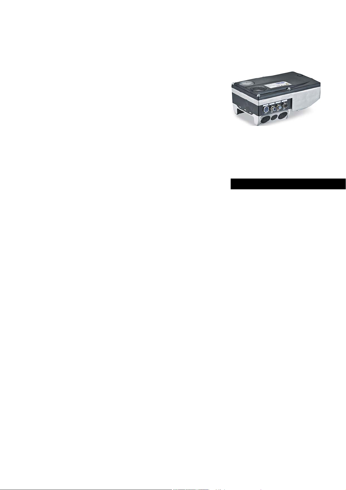
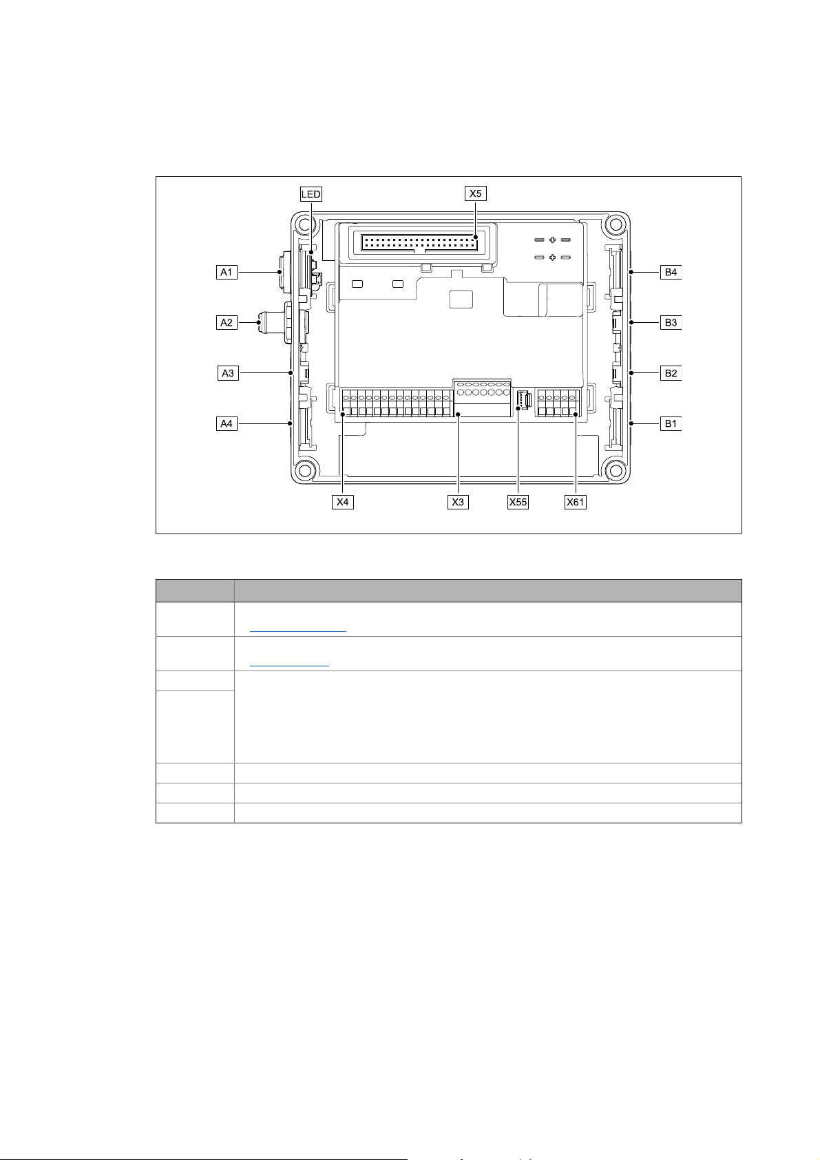
3.3 Connections and interfaces
[3-1] Communication Unit AS-Interface
Pos. Description
A1 / LED Position of LEDs for AS-i status display
LED status displays
A2 AS-i terminal (M12 pins, 5-pole)
AS-i connection
A3 / A4 Positions for further freely designable inputs and outputs:
B1 ... B4
X3 / X4 / X61 Terminal strips for wiring the terminals at A2 ... A4 and B1 ... B4
X5 Plug connector for connection to the Drive Unit
X55 Plug connector for the wiring of the LEDs to A1
• Digital inputs
•Digital output
• Analog input (only for E84DGFCAxJx)
• Relay output (only for E84DGFCAxJx)
• Connection of "Safety Option" safety system (only for E84DGFCAxJx)
E84DG018
( 53)
( 22)
14
Lenze · Decentralised frequency inverter 8400 motec (AS-Interface option) · EDS84DMOTASI EN 4.0 - 09/2013
Page 15

Product description
Connections and interfaces
_ _ _ _ _ _ _ _ _ _ _ _ _ _ _ _ _ _ _ _ _ _ _ _ _ _ _ _ _ _ _ _ _ _ _ _ _ _ _ _ _ _ _ _ _ _ _ _ _ _ _ _ _ _ _ _ _ _ _ _ _ _ _ _
• By default, the AS-i terminal and the LEDs for the AS-i status displays are already mounted and
wired:
• AS-i connection to terminal strip X3
• LEDs on plug connector X55
• The positions A1 ... A4 and B1 ... B4 serve to freely connect the AS-i terminals, the LEDs for the
AS-i status displays and other connections (e.g. digital inputs).
• For the connections, 5-pin M12 connectors or - alternatively - cable glands (cable cross-section
max. 1.0 mm
• The M12 connectors, cable glands and prefabricated system cables can be obtained from
various manufacturers.
• Wire the M12 plugs or cable glands used with the corresponding contacts of the terminal strips
X3, X4 and X61.
2
, AWG 18) can be used.
"Inverter Drives 8400 motec" hardware manual
Observe the notes and wiring instructions contained in this documentation.
Lenze · Decentralised frequency inverter 8400 motec (AS-Interface option) · EDS84DMOTASI EN 4.0 - 09/2013 15
Page 16

Technical data
General data and operating conditions
_ _ _ _ _ _ _ _ _ _ _ _ _ _ _ _ _ _ _ _ _ _ _ _ _ _ _ _ _ _ _ _ _ _ _ _ _ _ _ _ _ _ _ _ _ _ _ _ _ _ _ _ _ _ _ _ _ _ _ _ _ _ _ _
4 Technical data
"Inverter Drives 8400 motec" hardware manual
Here you will find the ambient conditions and information on the electromagnetic
compatibility (EMC) that also apply to the Communication Unit.
4.1 General data and operating conditions
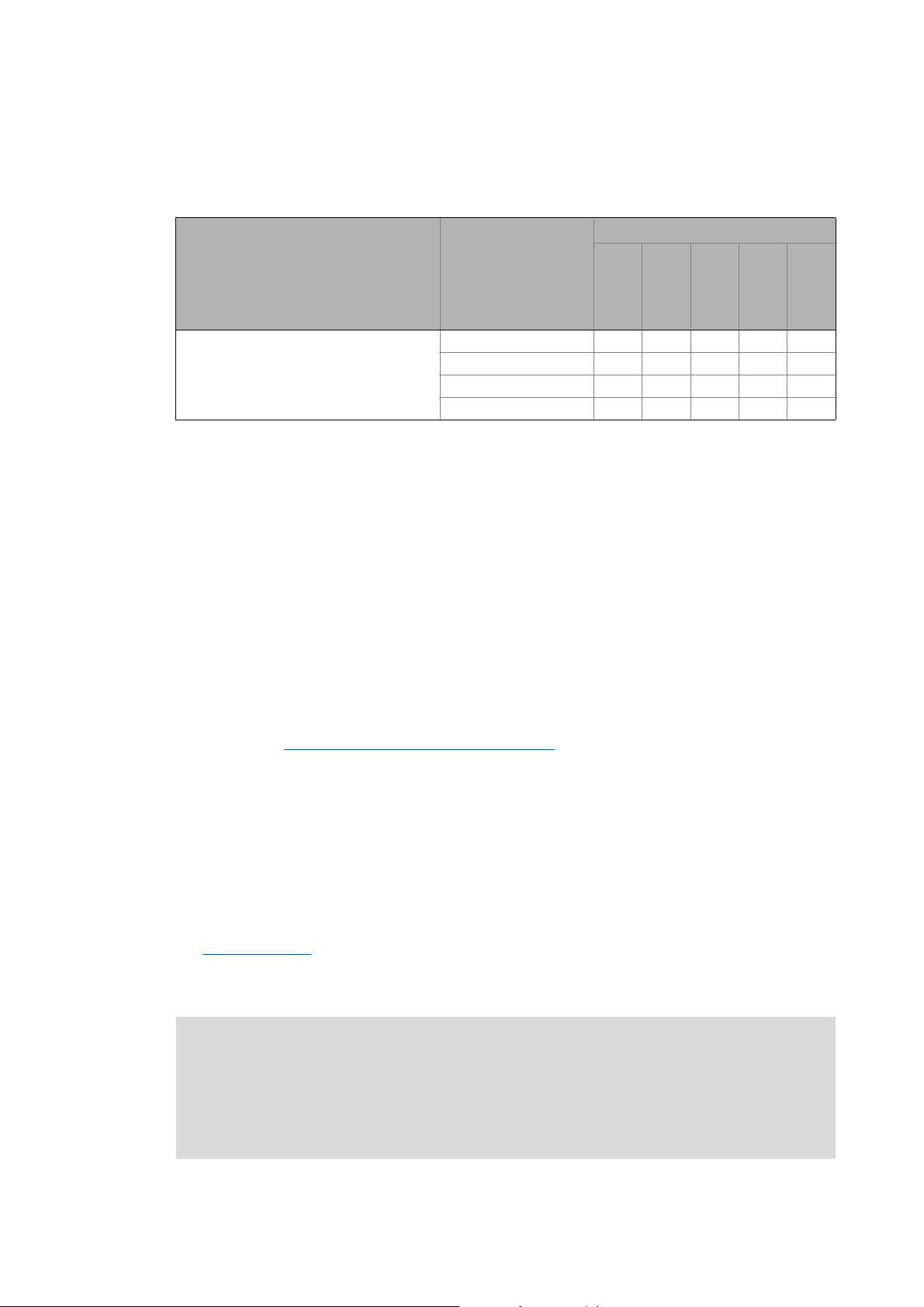
Range Values
Order designation • E84DGFCAxNx (AS-i V3)
• E84DGFCAxJx (AS-i V3, Safety)
Communication profile AS-Interface V3.0
Standards / specifications • EN 50295 / IEC 62026-2
• Safety engineering: EN 954-1, EN 13849-1, IEC 61508
(up to safety category 4)
2
Communication medium Two-wire cable for data and auxiliary power, 2 x 1.5 mm
(without shielding, without terminating impedance)
Interface for communication M12 pins, 5-pole, A-coded
• Contacting of the AS-i cable with penetration technique
• Cable with M12 socket, 5-pole, A-coded
Max. cable length • Max. 100 m without repeater/extender
• Max. 300 m with 2 repeaters/extenders
• Max. 500 m only for star topology with repeater/extender
Bus termination Only required for cable lengths > 100 m
Bus terminating resistors are required at the first and last AS-i node
(implemented in the connector of the bus cable)
Network topology Free topology (line, ring, tree, star)
Type of node Single slave or dual slave
Slave node number • Max. 31 standard slaves
• Max. 62 A/B slaves
Node address area 1 ... 31
Cycle time • max. 5 ms with maximum configuration
• 10 ms when A/B technique is used
• profile-specific with spec 3.0 slaves
Baud rate 167 kbps (gross)
53 kbps (net; data transfer efficiency = 32 %)
Voltage supply External supply via AS-i bus cable
• U = 29.5 ... 31.6 V (according to AS-i specification)
•I
= 400 mA
max
Available digital inputs • 5 dig. inputs with mains supply
• 4 dig. inputs with supply via AS-i bus and missing mains
Conformities, approvals • CE
•UR / cUR
(see also hardware manual)
16
Lenze · Decentralised frequency inverter 8400 motec (AS-Interface option) · EDS84DMOTASI EN 4.0 - 09/2013
Page 17

Technical data
Protocol data
_ _ _ _ _ _ _ _ _ _ _ _ _ _ _ _ _ _ _ _ _ _ _ _ _ _ _ _ _ _ _ _ _ _ _ _ _ _ _ _ _ _ _ _ _ _ _ _ _ _ _ _ _ _ _ _ _ _ _ _ _ _ _ _
4.2 Protocol data
Range Values
AS-i device profiles • Slave 1: 7.A.5 (CTT2)
• Slave 2: 7.A.E
Process image, standard Slave 1:
•DI0...3 = 4bits
• DO0 ... 3 = 4 bits
Slave 2:
•DI0/1 = 2 bits
•DO3/4 = 2 bits
Total: 6 input bits / 6 output bits
Process image, A/B technique Slave 1:
•DI0...3 = 4bits
• DO0 ... 2 = 3 bits
Slave 2:
•DI0/1 = 2 bits
•DO3 = 1 bits
Total: 6 input bits / 4 output bits
Cyclic parameter data channel
(AS-i spec. V2.0 and V3.0)
Acyclic parameter data channel
(AS-i spec. V3.0)
AS-i user data length max. 64 bytes
4 words (8 bytes)
max. 16 double words (64 bytes)
Lenze · Decentralised frequency inverter 8400 motec (AS-Interface option) · EDS84DMOTASI EN 4.0 - 09/2013 17
Page 18

Technical data
Communication time
_ _ _ _ _ _ _ _ _ _ _ _ _ _ _ _ _ _ _ _ _ _ _ _ _ _ _ _ _ _ _ _ _ _ _ _ _ _ _ _ _ _ _ _ _ _ _ _ _ _ _ _ _ _ _ _ _ _ _ _ _ _ _ _
4.3 Communication time
The communication time defines the time between the start of a request and the arrival of the
corresponding response.
The communication times in an AS-i network depend on the ...
• processing time in the inverter;
• telegram runtime (baud rate / telegram length);
• nesting depth of the network.
Processing time in the inverter
Data Processing time
Process data approx. 2 ms
+ 0 ... 1 ms
+ 1 ... x ms
Parameter data approx. 30 ms + a tolerance of 20 ms (typically)
For some codes, the processing time may be longer (see software manual/
»Engineer« online help "Inverter Drives 8400 motec").
Update cycle
Processing time in the module
Application task runtime of the use technology application
(tolerance)
There are no interdependencies between parameter data and process data.
18
Lenze · Decentralised frequency inverter 8400 motec (AS-Interface option) · EDS84DMOTASI EN 4.0 - 09/2013
Page 19

Installation
_ _ _ _ _ _ _ _ _ _ _ _ _ _ _ _ _ _ _ _ _ _ _ _ _ _ _ _ _ _ _ _ _ _ _ _ _ _ _ _ _ _ _ _ _ _ _ _ _ _ _ _ _ _ _ _ _ _ _ _ _ _ _ _
5 Installation
Stop!
Electrostatic discharge
Electronic components within the Communication Unit can be damaged or destroyed by
electrostatic discharge.
Possible consequences:
• The Communication Unit is defective.
• Fieldbus communication is not possible or faulty.
• I/O signals are faulty.
• The safety function is faulty.
Protective measures
Discharge electrostatic charges before touching the Communication Unit.
Lenze · Decentralised frequency inverter 8400 motec (AS-Interface option) · EDS84DMOTASI EN 4.0 - 09/2013 19
Page 20
Installation
Mechanical installation
_ _ _ _ _ _ _ _ _ _ _ _ _ _ _ _ _ _ _ _ _ _ _ _ _ _ _ _ _ _ _ _ _ _ _ _ _ _ _ _ _ _ _ _ _ _ _ _ _ _ _ _ _ _ _ _ _ _ _ _ _ _ _ _
5.1 Mechanical installation
"Inverter Drives 8400 motec" mounting instructions
Here you will find detailed information on the installation.
0.37 ... 3.0 kW 4.0 ... 7.5 kW
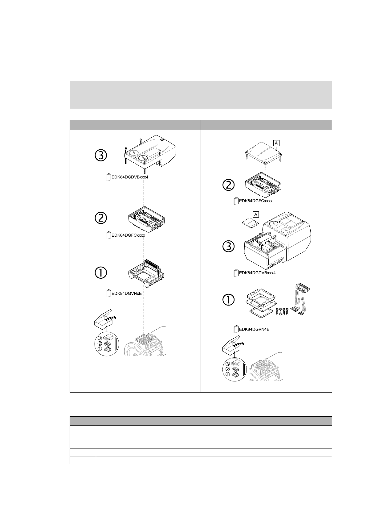
E84DG023a
E84DG023b
[5-1] Mechanical installation of the 8400 motec components
Legend for fig. [5-1]
1Drive Unit
2 Communication unit
3 Wiring Unit
A Cover of the Drive Unit
EDK84DG... Mounting instructions of the Drive Unit, Communication Unit, Wiring Unit
20
Lenze · Decentralised frequency inverter 8400 motec (AS-Interface option) · EDS84DMOTASI EN 4.0 - 09/2013
Page 21
Installation
Electrical installation
_ _ _ _ _ _ _ _ _ _ _ _ _ _ _ _ _ _ _ _ _ _ _ _ _ _ _ _ _ _ _ _ _ _ _ _ _ _ _ _ _ _ _ _ _ _ _ _ _ _ _ _ _ _ _ _ _ _ _ _ _ _ _ _
5.2 Electrical installation
"Inverter Drives 8400 motec" hardware manual
Here you can find detailed information on ...
• the digital and analog inputs/outputs;
•the relay output;
• the integrated safety system (safety option);
• the wiring of the terminals.
Observe the notes and wiring instructions contained in this documentation.
5.2.1 Bus cable specification
The AS-i bus cable serves as ...
•external Voltage supply
• a means for data transmission to and from the inverter.
( 23) of the Communication Unit;
Note!
Only use cables that comply with the listed specifications.
Range Values
Cable type Two-wire cable, insulated and shielded
Core cross-section 1.5 mm
Cable resistance < 90 m/m, (f = 3 ... 20 MHz)
Inductance 400 ... 1300 nH/m
Capacitance per unit length < 80 pF/m
Electrical master value < 5 μS/m
Surge impedance 70 ... 140
Group runtime < 8.3 ns/m
Tip!
These data are also met by several other standardised cables. An AS-i network can also be
set up with different cables. Multi-core cables (e.g. DeviceNet Thick Cable, DESINA cable/
light conductor) or busbars can be used for the setup of AS-i networks, too. In case of doubt,
consult a specialist in the planning phase.
Prefabricated system cables can be obtained from diverse manufacturers.
2
Lenze · Decentralised frequency inverter 8400 motec (AS-Interface option) · EDS84DMOTASI EN 4.0 - 09/2013 21
Page 22
Installation
Electrical installation
_ _ _ _ _ _ _ _ _ _ _ _ _ _ _ _ _ _ _ _ _ _ _ _ _ _ _ _ _ _ _ _ _ _ _ _ _ _ _ _ _ _ _ _ _ _ _ _ _ _ _ _ _ _ _ _ _ _ _ _ _ _ _ _
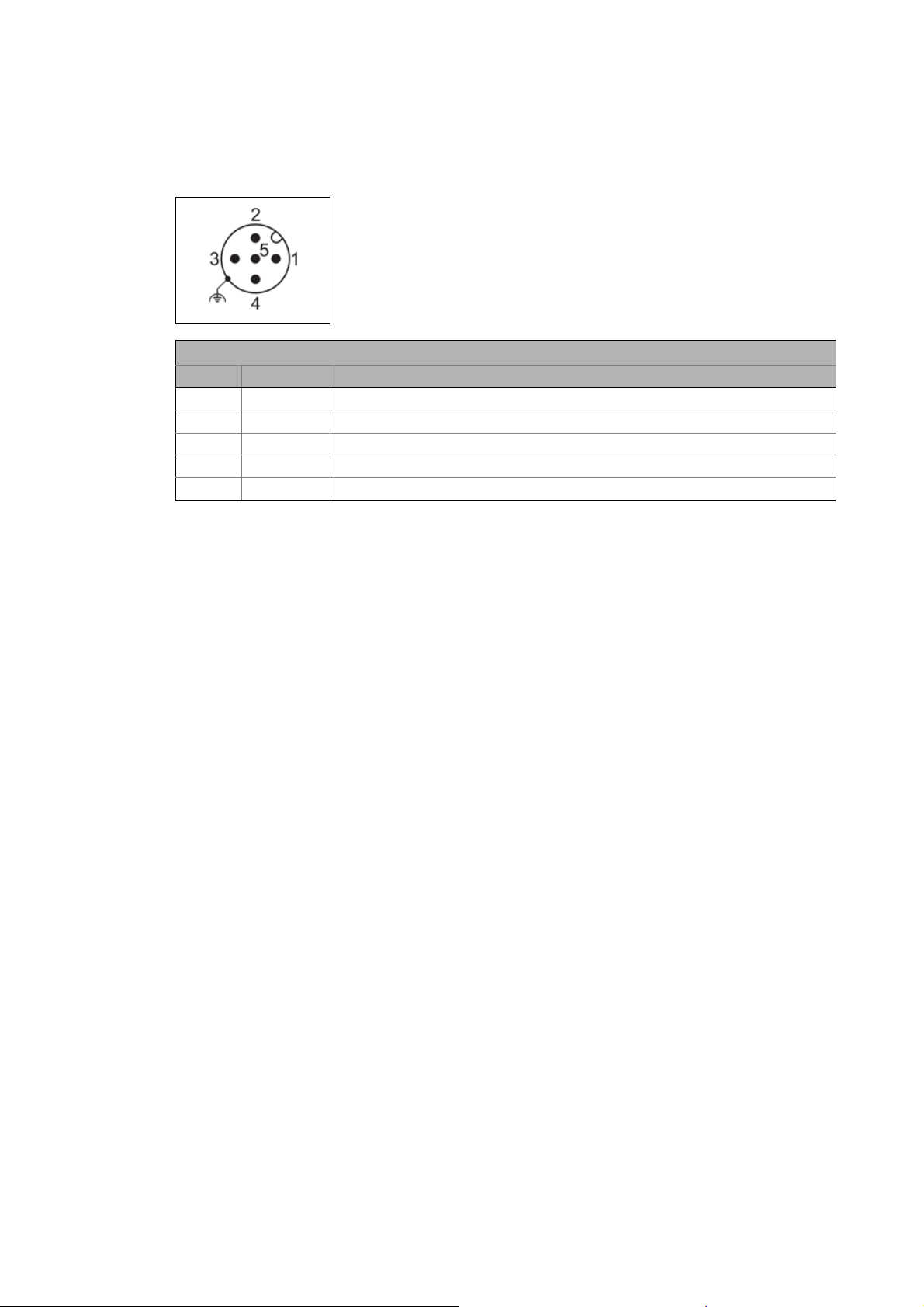
5.2.2 AS-i connection
• M12 pins, 5-pole, A-coded
• Wiring of terminal strip X3
AS-i connection
Pin Signal Description
1 ASi+ AS-i data line, positive
2 - Not assigned
3 ASi- AS-i data line, negative
4 - Not assigned
5 - Not assigned
22
Lenze · Decentralised frequency inverter 8400 motec (AS-Interface option) · EDS84DMOTASI EN 4.0 - 09/2013
Page 23

Installation
Electrical installation
_ _ _ _ _ _ _ _ _ _ _ _ _ _ _ _ _ _ _ _ _ _ _ _ _ _ _ _ _ _ _ _ _ _ _ _ _ _ _ _ _ _ _ _ _ _ _ _ _ _ _ _ _ _ _ _ _ _ _ _ _ _ _ _
5.2.3 Voltage supply
• The Communication Unit is supplied with voltage via the AS-i bus cable.
• Access to parameters of a device that is disconnected from the mains is not possible.
• Permissible voltage (DC) / max. current:
• U = 29.5 ... 31.6 V (according to AS-i specification)
•I
= 400 mA
max
Low-voltage supply via the AS-i-bus cable
In case of low-voltage supply via the AS-i bus cable, communication with the slaves is still possible
if no mains voltage is available.
• A previous mains connection (400 V) is not required.
• The digital inputs DI1 ... DI5, RFR and the analog input can still be evaluated.
• The AS-i input ports DI0 ... DI3 represent the digital inputs DI1 ... DI4 (see AS-i concept of the
Communication Unit ( 33)). The current status of these inputs can be called.
• All digital input and output data which can be selected by the inverter are deleted or invalid..
• External sensors are also supplied via the AS-i bus cable.
"Inverter Drives 8400 motec" hardware manual
Here you can find detailed information on how to wire the Communication Unit.
Lenze · Decentralised frequency inverter 8400 motec (AS-Interface option) · EDS84DMOTASI EN 4.0 - 09/2013 23
Page 24

Commissioning
Before initial switch-on
_ _ _ _ _ _ _ _ _ _ _ _ _ _ _ _ _ _ _ _ _ _ _ _ _ _ _ _ _ _ _ _ _ _ _ _ _ _ _ _ _ _ _ _ _ _ _ _ _ _ _ _ _ _ _ _ _ _ _ _ _ _ _ _
6 Commissioning
During commissioning, system-related data such as motor parameters, operating parameters,
responses, and parameters for fieldbus communication are defined for the drive. For Lenze devices,
this is done via the codes.
The codes of the drive and communication are saved non-volatilely as a data set in the memory
module.
In addition to codes for the configuration, there are codes for diagnosing and monitoring the nodes.
Parameter reference
6.1 Before initial switch-on
Stop!
Before you switch on the inverter for the first time, check the entire wiring for
completeness, short circuit, and earth fault.
( 60)
24
Lenze · Decentralised frequency inverter 8400 motec (AS-Interface option) · EDS84DMOTASI EN 4.0 - 09/2013
Page 25

Commissioning
How to configure the host (master)
_ _ _ _ _ _ _ _ _ _ _ _ _ _ _ _ _ _ _ _ _ _ _ _ _ _ _ _ _ _ _ _ _ _ _ _ _ _ _ _ _ _ _ _ _ _ _ _ _ _ _ _ _ _ _ _ _ _ _ _ _ _ _ _
6.2 How to configure the host (master)
For communication with the inverter, the host (master) must be configured first.
Defining the user data length
• The AS-Interface Communication Unit supports the configuration of max. 8 process data words
(max. 64 bytes).
• The user data length is defined during the initialisation phase of the master.
• The user data lengths for process input data and process output data are identical.
Note!
Observe the direction of the information flow.
• Process input data (Rx data):
Process data from the inverter (slave) to the host (master)
• Process output data (Tx data):
Process data from the host (master) to the inverter (slave)
Lenze · Decentralised frequency inverter 8400 motec (AS-Interface option) · EDS84DMOTASI EN 4.0 - 09/2013 25
Page 26

Commissioning
Settings for AS-i communication in the »Engineer«
_ _ _ _ _ _ _ _ _ _ _ _ _ _ _ _ _ _ _ _ _ _ _ _ _ _ _ _ _ _ _ _ _ _ _ _ _ _ _ _ _ _ _ _ _ _ _ _ _ _ _ _ _ _ _ _ _ _ _ _ _ _ _ _
6.3 Settings for AS-i communication in the »Engineer«
6.3.1 Addressing the AS-i slaves
Addressing is usually carried out automatically via the master or an external addressing unit.
The AS-Interface Communication Unit uses two slaves (see AS-i concept of the Communication Unit
( 33)) which must be initialised with unique addresses.
Note!
• If the same address is used for slave 1 and slave 2, the address of slave 2 is set to '0'.
• If address '0' is assigned to slave 1 and slave 2, slave 2 is switched "offline" (basic
settings remain intact).
•The setting C13200/x
visible in the AS-i network).
/ C13202/x = 64 serves to deactivate the slave (not active or
The parameters for addressing the AS-i slaves can be found in the »Engineer« on the "Settings" tab.
Setting / parameters Code
Slave 1: Address EPM value C13202/1
Slave 1: Address EPM value C13202/2
Override slave addresses C13204
26
Override of the slave addresses during
initialisation
Lenze · Decentralised frequency inverter 8400 motec (AS-Interface option) · EDS84DMOTASI EN 4.0 - 09/2013
C13205
Page 27

Commissioning
Settings for AS-i communication in the »Engineer«
_ _ _ _ _ _ _ _ _ _ _ _ _ _ _ _ _ _ _ _ _ _ _ _ _ _ _ _ _ _ _ _ _ _ _ _ _ _ _ _ _ _ _ _ _ _ _ _ _ _ _ _ _ _ _ _ _ _ _ _ _ _ _ _
6.3.2 All parameters for setting the AS-i communication
All parameters for setting the AS-i communication can be found in the »Engineer« on the "All
parameters" tab.
Save the changed settings with the device command C00002/11 (save all parameter sets).
Addressing the AS-i slaves
Parameters relevant for AS-i communication
( 26)
( 61)
Lenze · Decentralised frequency inverter 8400 motec (AS-Interface option) · EDS84DMOTASI EN 4.0 - 09/2013 27
Page 28

Commissioning
Initial switch-on
_ _ _ _ _ _ _ _ _ _ _ _ _ _ _ _ _ _ _ _ _ _ _ _ _ _ _ _ _ _ _ _ _ _ _ _ _ _ _ _ _ _ _ _ _ _ _ _ _ _ _ _ _ _ _ _ _ _ _ _ _ _ _ _
6.4 Initial switch-on
Establishing communication
• To establish a communication, the Inverter Drive must be supplied with mains voltage.
• For AS-i communication, the Communication Unit has to be supplied with voltage. If this is not
the case, the error message "CE04: MCI communication error" (error no. 01.0127.00002) is
output.
•The Voltage supply
case of a main supply failure.
• During mains connection, all parameters (codes) are read.
• Addressing can be carried out automatically via the master, an external addressing unit or
manually via codes in the »Engineer«.
Addressing the AS-i slaves
( 23) via the AS-i bus cable serves to maintain the AS-i communication in
( 26)
28
Lenze · Decentralised frequency inverter 8400 motec (AS-Interface option) · EDS84DMOTASI EN 4.0 - 09/2013
Page 29

Data transfer
AS-i messages
_ _ _ _ _ _ _ _ _ _ _ _ _ _ _ _ _ _ _ _ _ _ _ _ _ _ _ _ _ _ _ _ _ _ _ _ _ _ _ _ _ _ _ _ _ _ _ _ _ _ _ _ _ _ _ _ _ _ _ _ _ _ _ _
7 Data transfer
The AS-Interface transmits parameter data, configuration data, diagnostic data, alarm messages
and process data between the host (master) and the inverters (slaves) participating in the fieldbus.
Depending on their time-critical nature, the data are transmitted via different communication
channels.
The bus access method of the AS-Interface is a master-slave method with cyclic polling.
• The master transmits a frame (master call) with a specific slave address.
• The slave triggered with this address responds within the allowed time (acknowledgement of
the message).
• When the response has been received correctly from the master, the message is deemed to be
transmitted successfully.
• If the master does not receive any response or the response cannot be decoded without errors
for the master, the frame can be repeated.
7.1 AS-i messages
An AS-i message consists of ... a master call, a short pause, a slave response, and a short pause again.
• All master calls have a length of 14 bit times (1 bit time = 6 μs).
• All slave responses have a length of 7 bit times.
• The 1st pause has a typical duration of 16 μs (synchronised slave) and must not be longer than
the expected slave response.
If during this time the master does not receive the start of a slave response, no response will
arrive anymore. Now the master may start with the next call.
• At the end of the slave response, there is a short pause again with a typical duration of approx.
9…12μs.
The master needs this time to check the slave response and decide what should happen next
(repeat the transmitted call or continue with the next call).
Broadcast call of the master
An exception to this message structure is a broadcast request of the master. A broadcast
transmission corresponds to broadcasting to all nodes (simultaneous transmission from the master
to all slaves). It can only be effected in one direction. Broadcast transmissions cannot be
acknowledged. Hence, it is not ensured that all slaves have received the message correctly.
Master call Pause 1 Slave response Pause 2
14 bits 7 bits
84 μs 16 μs 42 μs9...12μs
151 ... 154 μs
Lenze · Decentralised frequency inverter 8400 motec (AS-Interface option) · EDS84DMOTASI EN 4.0 - 09/2013 29
Page 30

Data transfer
AS-i messages
_ _ _ _ _ _ _ _ _ _ _ _ _ _ _ _ _ _ _ _ _ _ _ _ _ _ _ _ _ _ _ _ _ _ _ _ _ _ _ _ _ _ _ _ _ _ _ _ _ _ _ _ _ _ _ _ _ _ _ _ _ _ _ _
Structure of the master call
Structure in the standard addressing mode for up to 31 slaves:
ST SB Address Information PB EB
1 bit 1 bit 5 bits 5 bits 1 bit 1 bit
Structure in the advanced addressing mode for up to 62 slaves:
ST SB Address Information PB EB
1 bit 1 bit 5 bits 1 bit Select
Bit field Description
ST The start bit marks the start of the master call.
•0: Valid start bit
•1: Not permitted
SB The control bit designates the call of data, parameters, addressing or commands.
• 0: Data/parameter/addressing call
•1: Command call
Address • 5 address bits contain the address of the slave to be called.
• Valid address range: 1 ... 31
Information Depending on the call type, the information bits contain the information that is transmitted
to the slave.
• 5 information bits in standard addressing mode
• 4 information bits in advanced addressing mode
Advanced addressing mode:
• For the advanced addressing mode (for up to 62 slaves), an additional select bit has been
defined.
• This has been defined in order that an A slave behaves the same as a standard slave. An
A slave can also be operated in networks where the master cannot distinguish between
A and B slaves. A/B slaves can be recognised by the hexadecimal ID code "0xA".
• Valid address range: 1A ... 31A, 1B ... 31B
PB Parity bit: The sum of all 1 bit states in the master call must be even.
EB The end bit marks the end of the master call.
•0: Not permitted
• 1: Valid end bit
bit
3 bits 1 bit 1 bit
30
Structure of the slave response
ST Information PB EB
1 bit 4 bits 1 bit 1 bit
Bit field Description
ST The start bit marks the start of the slave response.
•0: Valid start bit
•1: Not permitted
Information The 4 information bits contain the information that is transmitted to the master.
PB Parity bit: The sum of all 1 bit states in the slave response must be even.
EB The end bit marks the end of the slave response.
•0: Not permitted
• 1: Valid end bit
Lenze · Decentralised frequency inverter 8400 motec (AS-Interface option) · EDS84DMOTASI EN 4.0 - 09/2013
Page 31

Data transfer
AS-i cycle
_ _ _ _ _ _ _ _ _ _ _ _ _ _ _ _ _ _ _ _ _ _ _ _ _ _ _ _ _ _ _ _ _ _ _ _ _ _ _ _ _ _ _ _ _ _ _ _ _ _ _ _ _ _ _ _ _ _ _ _ _ _ _ _
7.2 AS-i cycle
The complete AS-i cycle consists of:
• AS-i messages
Max. 31 messages (sum of the standard slaves connected to the network or the maximum of A
and B slaves)
• 1 management call
Consists of a parameter exchange or a command to a slave and an optional response.
• 1 call from the recording phase
Search for new slave addresses and optional response
• 1 reserve message (if required)
Cycle time
• The cycle time results from the following formula:
Cycle time = messages per cycle x max. message duration
• When the maximum cycle time is determined, 33 messages are maximally estimated. Hence:
Max. cycle time = 33 messages x 154 μs = 5.08 ms
• Thus, approx. 200 cycles are passed per second.
• Thus, a standard slave can be provided 200 times per second with new output data and can
transmit its input data to the master.
Note!
Wherever A and B slaves are operated on one address, the cycle time is twice as long.
Medium response time
• The medium response time results from the following formula:
Medium response time = 0.5 x max. cycle time + max. message duration
Medium response time = 0.5 x 5.08 ms + 154 μs= 2.7ms
•The jitter, which is the fluctuation around the medium response time, amounts to ...
• ± 2.5 ms for standard slaves;
•±5.0 ms for A/B slaves.
Note!
Wherever A and B slaves are operated on one address, the medium response time is
twice as long (5.4 ms).
Lenze · Decentralised frequency inverter 8400 motec (AS-Interface option) · EDS84DMOTASI EN 4.0 - 09/2013 31
Page 32

Data transfer
Synchronisation
_ _ _ _ _ _ _ _ _ _ _ _ _ _ _ _ _ _ _ _ _ _ _ _ _ _ _ _ _ _ _ _ _ _ _ _ _ _ _ _ _ _ _ _ _ _ _ _ _ _ _ _ _ _ _ _ _ _ _ _ _ _ _ _
7.3 Synchronisation
The synchronisation serves to read in or output all input and output data exactly at the same time
and independent of the slave address. The jitter of the outputs can be reduced from ± 2.5 ms to
±154μs.
In a standard data exchange, the outputs of each slave that receives a data call from the master are
updated immediately and the input information are read in. For the 1st slave, this occurs approx.
154 μs before the 2nd slave and for this slave again approx. 154 μs before the 3rd etc.
If all the slaves are in a synchronised state, the information at their inputs and outputs is only
synchronised once at the beginning of the cycle. Since each slave can recognise when a new AS-i
cycle starts, no special additional synchronisation command is required. Thus, the information
exchange within the cycle remains the same. In order that the synchronisation works, not every
slave has to be in a synchronised state.
32
Lenze · Decentralised frequency inverter 8400 motec (AS-Interface option) · EDS84DMOTASI EN 4.0 - 09/2013
Page 33

Data transfer
AS-i concept of the Communication Unit
_ _ _ _ _ _ _ _ _ _ _ _ _ _ _ _ _ _ _ _ _ _ _ _ _ _ _ _ _ _ _ _ _ _ _ _ _ _ _ _ _ _ _ _ _ _ _ _ _ _ _ _ _ _ _ _ _ _ _ _ _ _ _ _
7.4 AS-i concept of the Communication Unit
The AS-Interface Communication Unit supports the following device profiles:
AS-i profile Slave Data transmission Data / parameter bits
7.A.5 1 Cyclic process image DI0/1, DO2/3
Serial data transmission (CTT2):
Acyclic transmission of data records and cyclic transmission
of the extended process image
Extended process image for slave 1
7.A.E 2 Cyclic process image DI0 ... 3, DO0 ... 3
Diagnostics via parameter data channel (parameter echo) P0 ... P3
( 35)
DI2/3, DO0/1
[7-1] AS-i concept of the Communication Unit
Lenze · Decentralised frequency inverter 8400 motec (AS-Interface option) · EDS84DMOTASI EN 4.0 - 09/2013 33
Page 34

Data transfer
Data transmission slave 1 (AS-i profile 7.A.5)
_ _ _ _ _ _ _ _ _ _ _ _ _ _ _ _ _ _ _ _ _ _ _ _ _ _ _ _ _ _ _ _ _ _ _ _ _ _ _ _ _ _ _ _ _ _ _ _ _ _ _ _ _ _ _ _ _ _ _ _ _ _ _ _
7.5 Data transmission slave 1 (AS-i profile 7.A.5)
Accessing the data bits
Bits Signal / I/O mapping Description / standard connection with ...
Inputs
DI0 DigIn_bIn2 The function of these inputs cannot be selected in the
DI1 DigIn_bIn4
DI2 Serial Clock In Intended for CTT2 transmission.
DI3 Serial Data In
Outputs
DO0 Serial Clock Out Intended for CTT2 transmission.
DO1 Serial Data Out
DO2 LP_Network_In: MCI_bCtrl_B3 C00701/3: not connected
DO3 Reserved Reserved for AS-i A/B addressing
»Engineer«.
Can be used to monitor the digital inputs if the Drive Unit is
in the "offline" status.
Accessing the parameter bits
Bits Signal / I/O mapping Description
P0 Reserved Selection of the process image:
• 0: Data of the extended (cyclic) process image 1
• 1: Data of the extended (cyclic) process image 2
Extended process image for slave 1
P1 Reserved
P2 Reserved
P3 Reserved Reserved for AS-i A/B addressing
( 35)
34
Lenze · Decentralised frequency inverter 8400 motec (AS-Interface option) · EDS84DMOTASI EN 4.0 - 09/2013
Page 35

Data transfer
Data transmission slave 1 (AS-i profile 7.A.5)
_ _ _ _ _ _ _ _ _ _ _ _ _ _ _ _ _ _ _ _ _ _ _ _ _ _ _ _ _ _ _ _ _ _ _ _ _ _ _ _ _ _ _ _ _ _ _ _ _ _ _ _ _ _ _ _ _ _ _ _ _ _ _ _
Extended process image for slave 1
Extended process image 1 - PR0 = 0
Position Signal / I/O mapping
Master Slave (2 x 16 bits/word)
Word 1 MCI_wIn2/CAN1_wIn2
Word 2 MCI_wIn5/CAN2_wIn1
Slave Master (2 x 16 bits/word)
Word 1 MCI_wOut2/CAN1_wOut2
Word 2 MCI_wOut5/CAN2_wOut1
Extended process image 2 - PR0 = 1
Position Signal / I/O mapping Description
Master Slave (2 x 16 bits/word)
Word 1 MCI_wIn2/CAN1_wIn2
Word 2 MCI_wIn5/CAN2_wIn1
Slave Master (2 x 16 bits/word)
Word 1 MCI_wOut2/CAN1_wOut2
Word 2:
Bits 0 ... 9
Word 2:
Bit 10
Word 2:
Bit 11
Word 2:
Bit 12
Word 2:
Bit 13
Word 2:
Bit 14
Word 2:
Bit 15
0...10V
(Voltage at analog input)
DI3 0: Active
DI4
DI5
Reserved
I/O status information 0: Invalid data in word 1, word 2
Status of the drive (Drive Unit) 0: Drive (Drive Unit) is "offline"
10 V = 1000
1: Not active
1: Valid data in word 1, word 2
1: Drive (Drive Unit) is "online"
Lenze · Decentralised frequency inverter 8400 motec (AS-Interface option) · EDS84DMOTASI EN 4.0 - 09/2013 35
Page 36

Data transfer
Data transmission slave 2 (AS-i profile 7.A.E)
_ _ _ _ _ _ _ _ _ _ _ _ _ _ _ _ _ _ _ _ _ _ _ _ _ _ _ _ _ _ _ _ _ _ _ _ _ _ _ _ _ _ _ _ _ _ _ _ _ _ _ _ _ _ _ _ _ _ _ _ _ _ _ _
7.6 Data transmission slave 2 (AS-i profile 7.A.E)
Accessing the data bits
Bits Signal / I/O mapping Description / standard connection with ...
Inputs
DI0 LP_Network_Out: MCI_bState_B0 C00621/30: not connected
DI1 LP_Network_Out: MCI_bState_B1 C00621/31: not connected
DI2 Digin_bln1 The function of these inputs cannot be selected in the
DI3 Digin_bln3
Outputs
DO0 LP_Network_In: MCI_bCtrl_B0 C00701/1: not connected
DO1 LP_Network_In: MCI_bCtrl_B1 C00701/6: not connected
DO2 LP_Network_In: MCI_bCtrl_B2 C00701/5: not connected
DO3 Reserved Reserved for AS-i A/B addressing
»Engineer«.
Can be used to monitor the digital inputs if the Drive Unit is
in the "offline" status.
36
Lenze · Decentralised frequency inverter 8400 motec (AS-Interface option) · EDS84DMOTASI EN 4.0 - 09/2013
Page 37

Data transfer
Data transmission slave 2 (AS-i profile 7.A.E)
_ _ _ _ _ _ _ _ _ _ _ _ _ _ _ _ _ _ _ _ _ _ _ _ _ _ _ _ _ _ _ _ _ _ _ _ _ _ _ _ _ _ _ _ _ _ _ _ _ _ _ _ _ _ _ _ _ _ _ _ _ _ _ _
Accessing the parameter bits
Parameter bits P0 ... P3 provide diagnostic information to the master for slave 2. Here, P0 ... P2
define whether a status query of code C00150 or an error/warning diagnostics is returned as slave
response to the master.
The values of P0 ... P3 are transmitted to the master via the "Write_Parameter" command.
Bits Signal / I/O mapping Description
P0 Diagnostic information
P1
P2
P3
(slave master):
• 4 status bits of the status word
C00150
• Error messages / warnings (see
below)
Error messages and warnings
Values P0 - P1 - P2:
• 0 - 0 - 0: Query C00150/Bits 0 ... 3
• 0 - 0 - 1: Query C00150/Bits 4 ... 7
• 0 - 1 - 0: Query C00150/Bits 8 ... 11
• 0 - 1 - 1: Query C00150/Bits 12 ... 15
• 1 - 0 - 0: Active error
• 1 - 0 - 1: Active warning
Note!
No error message / warning is ever provided other than the one with the highest priority.
As long as this error message / warning is pending, no other can be provided.
Values Error message Warning
P0 P1 P2 P3
0 0 0 0 No failure No warning
0001"OC1" - Short circuit "OC5" - Device load warning
0010"OC2" - Ground fault "OC6" - Overload warning
0011 "OH" - High temperature Heat sink temperature high warning
0 1 0 0 "US02" - User error #1 "US01" - User warning #1
0 1 0 1 "OU" - High bus voltage Brake resistor overload
0 1 1 0 "LU" - Low bus voltage error "LU" - Low bus voltage warning
0 1 1 1 "OC6" - Overload error Motor identification active
1 0 0 0 "Su02" - Single phasing "Su02" - Single phasing
1 0 0 1 "US02" - User error #2 "US02" - User warning #2
1 0 1 0 "dbF" - Dynamic brake fault AutoStartLock
1 0 1 1 "PS0x" - EPM failure Motor phase failure
1 1 0 0 "DF0x" - Internal failure AIN current < 4 mA
1101"OH3" - PTC fault Reserved (unused)
1 1 1 0 Drive Unit "offline" Reserved (unused)
1111Other failure Other warnings
Lenze · Decentralised frequency inverter 8400 motec (AS-Interface option) · EDS84DMOTASI EN 4.0 - 09/2013 37
Page 38

Process data transfer
_ _ _ _ _ _ _ _ _ _ _ _ _ _ _ _ _ _ _ _ _ _ _ _ _ _ _ _ _ _ _ _ _ _ _ _ _ _ _ _ _ _ _ _ _ _ _ _ _ _ _ _ _ _ _ _ _ _ _ _ _ _ _ _
8 Process data transfer
• Process data are transmitted via the process data channel.
• The process data serve to control the inverter.
• The transmission of process data is time-critical.
• Process data are cyclically transferred between the master and the slaves participating in the
fieldbus (continuous exchange of current input and output data).
• The master can directly access the process data. In the PLC, for instance, the data are directly
assigned to the I/O area.
• Process data are not saved in the inverter.
• Process data are e.g. setpoints, actual values, control words, and status words.
Note!
Observe the direction of the information flow.
• Process input data (Rx data):
Process data from the inverter (slave) to the host (master)
• Process output data (Tx data):
Process data from the host (master) to the inverter (slave)
38 Lenze · Decentralised frequency inverter 8400 motec (AS-Interface option) · EDS84DMOTASI EN 4.0 - 09/2013
Page 39

Process data transfer
Accessing process data / PDO mapping
_ _ _ _ _ _ _ _ _ _ _ _ _ _ _ _ _ _ _ _ _ _ _ _ _ _ _ _ _ _ _ _ _ _ _ _ _ _ _ _ _ _ _ _ _ _ _ _ _ _ _ _ _ _ _ _ _ _ _ _ _ _ _ _
8.1 Accessing process data / PDO mapping
Process data are transferred via the MCI/CAN interface.
• The process data is accessed via the LP_Network_In and LP_Network_Out port blocks.
• Up to 8 words (16 bits/word) per direction can be exchanged.
• The port/function blocks of the process data objects (PDO) are interconnected via the Lenze
»Engineer«.
[8-1] Outer and inner data transfer between bus system, drive and application
Software manual / »Engineer« online help for the Inverter Drive 8400 motec
Here you will find detailed information on the port/function block interconnection in
the »Engineer« and on the port blocks.
Lenze · Decentralised frequency inverter 8400 motec (AS-Interface option) · EDS84DMOTASI EN 4.0 - 09/2013 39
Page 40

Process data transfer
Port interconnection of process data objects (PDO)
_ _ _ _ _ _ _ _ _ _ _ _ _ _ _ _ _ _ _ _ _ _ _ _ _ _ _ _ _ _ _ _ _ _ _ _ _ _ _ _ _ _ _ _ _ _ _ _ _ _ _ _ _ _ _ _ _ _ _ _ _ _ _ _
8.2 Port interconnection of process data objects (PDO)
How to configure the port interconnection in the »Engineer«:
1. Go to the Application parameters tab to make the default setting of the I/O configuration.
Select the "Network (ASi)" control mode (C00007).
2. The Process data objects tab of the AS-i interface displays the preset I/O configuration.
40
Lenze · Decentralised frequency inverter 8400 motec (AS-Interface option) · EDS84DMOTASI EN 4.0 - 09/2013
Page 41

Process data transfer
Port interconnection of process data objects (PDO)
_ _ _ _ _ _ _ _ _ _ _ _ _ _ _ _ _ _ _ _ _ _ _ _ _ _ _ _ _ _ _ _ _ _ _ _ _ _ _ _ _ _ _ _ _ _ _ _ _ _ _ _ _ _ _ _ _ _ _ _ _ _ _ _
3. Open the "Assignment Signal --> Function Block" dialog window using the buttons.
Here, tick (
) the signals that are sent from the PLC (AS-i master) to the inverter.
4. Confirm the selection with OK.
Lenze · Decentralised frequency inverter 8400 motec (AS-Interface option) · EDS84DMOTASI EN 4.0 - 09/2013 41
Page 42

Process data transfer
Port interconnection of process data objects (PDO)
_ _ _ _ _ _ _ _ _ _ _ _ _ _ _ _ _ _ _ _ _ _ _ _ _ _ _ _ _ _ _ _ _ _ _ _ _ _ _ _ _ _ _ _ _ _ _ _ _ _ _ _ _ _ _ _ _ _ _ _ _ _ _ _
5. The codes C00620/21, C00620/24, C00621/30 and C00621/31 serve to
select the signals that are sent from the inverter to the PLC (AS-i master).
6. Use code C00002 to execute the command "11: Save all parameter sets".
The changed settings are activated and saved safe against mains failure.
42
Lenze · Decentralised frequency inverter 8400 motec (AS-Interface option) · EDS84DMOTASI EN 4.0 - 09/2013
Page 43

Parameter data transfer
_ _ _ _ _ _ _ _ _ _ _ _ _ _ _ _ _ _ _ _ _ _ _ _ _ _ _ _ _ _ _ _ _ _ _ _ _ _ _ _ _ _ _ _ _ _ _ _ _ _ _ _ _ _ _ _ _ _ _ _ _ _ _ _
9 Parameter data transfer
• Parameter data are acyclically transmitted via the parameter data channel.
• The parameter data channel provides access to all Lenze codes.
• In general, the transmission of parameter data is not time-critical.
• Parameter data are, for instance, operating parameters, diagnostic information, and motor
data.
• Parameter data transfer of the AS-Interface Communication Unit is done acyclically by means
of serial CTT2 transmission (combined transaction type 2).
Lenze · Decentralised frequency inverter 8400 motec (AS-Interface option) · EDS84DMOTASI EN 4.0 - 09/2013 43
Page 44

Parameter data transfer
CTT2: Read parameter value
_ _ _ _ _ _ _ _ _ _ _ _ _ _ _ _ _ _ _ _ _ _ _ _ _ _ _ _ _ _ _ _ _ _ _ _ _ _ _ _ _ _ _ _ _ _ _ _ _ _ _ _ _ _ _ _ _ _ _ _ _ _ _ _
9.1 CTT2: Read parameter value
• Acyclic read request from the master to the slave:
Byte Contents / value
0 CTT2: Code
•Index 0x12 (18): Acyclic read request
1 CTT2: Index
•Index 0x10 (16): Read parameter value
2 CTT2: Number of bytes
• Value depends on the master.
• Response from slave to master is OK:
Byte Contents / value
0 CTT2: Code
•Index 0x52 (82): Acyclic read request is OK.
1 Data type / number of bytes
Bit 7 = 0 Octet string (text)
• Bits 0 ... 6 = Number of string characters
Bit 7 = 1 Number (4 data bytes):
• Bits 0 ... 2 = Number of valid bytes
(1 = 1 byte, 2 = 2 bytes, 3 = 3 bytes, 4 = 4 bytes)
2 1st character of the character string or data byte 1 (MSB)
3 2nd character of the string or data byte 2
4 3rd character of the string or data byte 3
5 4th character of the string or data byte 4 (LSB)
6 5th character of the string
... ...
n n-th character of the string
• Response from slave to master has failed:
Byte Contents / value
0 CTT2: Code
•Index 0x92 (146): Acyclic read request is not OK.
1 CTT2: Standard error code
CTT2: Standard error codes
2Error code (MSB)
3Error code
4Error code
5Error code (LSB)
CTT2: Acyclic device error codes
( 51)
( 52)
44
Lenze · Decentralised frequency inverter 8400 motec (AS-Interface option) · EDS84DMOTASI EN 4.0 - 09/2013
Page 45

Parameter data transfer
CTT2: Write parameter value
_ _ _ _ _ _ _ _ _ _ _ _ _ _ _ _ _ _ _ _ _ _ _ _ _ _ _ _ _ _ _ _ _ _ _ _ _ _ _ _ _ _ _ _ _ _ _ _ _ _ _ _ _ _ _ _ _ _ _ _ _ _ _ _
9.2 CTT2: Write parameter value
• Acyclic write request from master to slave:
Byte Contents / value
0 CTT2: Code
•Index 0x13 (19): Acyclic write request
1 CTT2: Index
•Index 0x18 (24): Write parameter value
2 CTT2: Number of bytes
• 0x8 (8)
3Index high
byte
4Index low
byte
5Subindex
6 Data type / number of bytes
Bit 7 = 0 Number (4 data bytes):
Bit 7 must be "0". Writing the string is not supported.
7 Data byte 1 (MSB)
8 Data byte 2
9 Data byte 3
10 Data byte 4 (LSB)
Index = 0x5FFF (code to be written)
• Bits 0 ... 2 = Number of valid bytes
(1 = 1 byte, 2 = 2 bytes, 3 = 3 bytes, 4 = 4 bytes)
• Response from slave to master is OK:
Byte Contents / value
0 CTT2: Code
•Index 0x53 (83): Acyclic write request is OK.
• Parameter value was written.
• Response from slave to master has failed:
Byte Contents / value
0 CTT2: Code
•Index 0x93 (147): Acyclic write request is not OK.
1 CTT2: Standard error code
CTT2: Standard error codes
2Error code (MSB)
3Error code
4Error code
5Error code (LSB)
CTT2: Acyclic device error codes
( 51)
( 52)
Lenze · Decentralised frequency inverter 8400 motec (AS-Interface option) · EDS84DMOTASI EN 4.0 - 09/2013 45
Page 46

Parameter data transfer
CTT2: Read code number
_ _ _ _ _ _ _ _ _ _ _ _ _ _ _ _ _ _ _ _ _ _ _ _ _ _ _ _ _ _ _ _ _ _ _ _ _ _ _ _ _ _ _ _ _ _ _ _ _ _ _ _ _ _ _ _ _ _ _ _ _ _ _ _
9.3 CTT2: Read code number
• Acyclic read request from the master to the slave:
Byte Contents / value
0 CTT2: Code
•Index 0x12 (18): Acyclic read request
1 CTT2: Index
•Index 0x12 (18): Read code number
2 CTT2: Number of bytes
• Value depends on the master.
• Response from slave to master is OK:
Byte Contents / value
0 CTT2: Code
•Index 0x52 (82): Acyclic read request is OK.
3Index high
byte
4Index low
byte
5Subindex
6 Reserved
Index = 0x5FFF (code of the inverter)
• Response from slave to master has failed:
Byte Contents / value
0 CTT2: Code
•Index 0x92 (146): Acyclic read request is not OK.
1 CTT2: Standard error code
CTT2: Standard error codes
2Error code (MSB)
3Error code
4Error code
5Error code (LSB)
CTT2: Acyclic device error codes
( 51)
( 52)
46
Lenze · Decentralised frequency inverter 8400 motec (AS-Interface option) · EDS84DMOTASI EN 4.0 - 09/2013
Page 47

Parameter data transfer
CTT2: Write code number
_ _ _ _ _ _ _ _ _ _ _ _ _ _ _ _ _ _ _ _ _ _ _ _ _ _ _ _ _ _ _ _ _ _ _ _ _ _ _ _ _ _ _ _ _ _ _ _ _ _ _ _ _ _ _ _ _ _ _ _ _ _ _ _
9.4 CTT2: Write code number
• Acyclic write request from master to slave:
Byte Contents / value
0 CTT2: Code
•Index 0x13 (19): Acyclic write request
1 CTT2: Index
•Index 0x11 (17): Write code number
2 CTT2: Number of bytes
• 0x4 (4)
3Index high
byte
4Index low
byte
5Subindex
6 Reserved
Index = 0x5FFF (code of the inverter)
• Response from slave to master is OK:
Byte Contents / value
0 CTT2: Code
•Index 0x53 (83): Acyclic write request is OK.
• Code number was written.
• Response from slave to master has failed:
Byte Contents / value
0 CTT2: Code
•Index 0x93 (147): Acyclic write request is not OK.
1 CTT2: Standard error code
CTT2: Standard error codes
2Error code (MSB)
3Error code
4Error code
5Error code (LSB)
CTT2: Acyclic device error codes
( 51)
( 52)
Lenze · Decentralised frequency inverter 8400 motec (AS-Interface option) · EDS84DMOTASI EN 4.0 - 09/2013 47
Page 48

Parameter data transfer
CTT2: Block parameter transfer
_ _ _ _ _ _ _ _ _ _ _ _ _ _ _ _ _ _ _ _ _ _ _ _ _ _ _ _ _ _ _ _ _ _ _ _ _ _ _ _ _ _ _ _ _ _ _ _ _ _ _ _ _ _ _ _ _ _ _ _ _ _ _ _
9.5 CTT2: Block parameter transfer
In the case of the CTT2 block parameter transfer, parameter sets with a fixed length of 64 bytes are
transmitted.
Note!
In order to guarantee that a fixed data length of 64 bytes is transmitted, all the
parameters are transmitted as 32-bit values (16 x 32-bit parameters).
If required, the data lengths or formats of the parameters must be adjusted accordingly.
Parameter data smaller than 32 bits are not extended to 32 bits.
9.5.1 Read mode
• Acyclic read request from the master to the slave:
Byte Contents / value
0 CTT2: Code
•Index 0x12 (18): Acyclic read request
1 CTT2: Index
•Index 0x20 (32): Read parameter
2 CTT2: Number of bytes
• Value depends on the master.
• Response from slave to master is OK:
Byte Contents / value
0 CTT2: Code
•Index 0x52 (82): Acyclic read request is OK.
• All the parameters were read.
1 Reserved
2 Reserved
3 Reserved
4 ... 7 Double word 1
• Value of the parameter in code C13214/1
... ...
64 ... 67 Double word 16
• Value of the parameter in code C13214/16
48
Lenze · Decentralised frequency inverter 8400 motec (AS-Interface option) · EDS84DMOTASI EN 4.0 - 09/2013
Page 49

Parameter data transfer
CTT2: Block parameter transfer
_ _ _ _ _ _ _ _ _ _ _ _ _ _ _ _ _ _ _ _ _ _ _ _ _ _ _ _ _ _ _ _ _ _ _ _ _ _ _ _ _ _ _ _ _ _ _ _ _ _ _ _ _ _ _ _ _ _ _ _ _ _ _ _
• Response from slave to master has failed:
Byte Contents / value
0 CTT2: Code
•Index 0x92 (146): Acyclic read request is not OK.
• Read exception list (index 0x21 (33))
1 CTT2: Standard error code
CTT2: Standard error codes
2Error code (MSB)
3Error code
4Error code
5Error code (LSB)
CTT2: Acyclic device error codes
• After the acyclic read request (index 0x12 (18)) has failed, the master sends error codes.
• Then the read request from master to slave with the index 0x21 (33) is repeated.
• The slave sends the parameter values in code C13214/1...16
( 51)
( 52)
again.
Lenze · Decentralised frequency inverter 8400 motec (AS-Interface option) · EDS84DMOTASI EN 4.0 - 09/2013 49
Page 50

Parameter data transfer
CTT2: Block parameter transfer
_ _ _ _ _ _ _ _ _ _ _ _ _ _ _ _ _ _ _ _ _ _ _ _ _ _ _ _ _ _ _ _ _ _ _ _ _ _ _ _ _ _ _ _ _ _ _ _ _ _ _ _ _ _ _ _ _ _ _ _ _ _ _ _
9.5.2 Write mode
• Acyclic write request from master to slave:
Byte Contents / value
0 CTT2: Code
•Index 0x13 (19): Acyclic write request
1 CTT2: Index
•Index 0x28 (40): Write parameter
2 CTT2: Number of bytes
• 0x41 (65)
3 Reserved
4 ... 7 Double word 1
• Value of the parameter in code C13213/1
... ...
64 ... 67 Double word 16
• Value of the parameter in code C13213/16
• Response from slave to master is OK:
Byte Contents / value
0 CTT2: Code
•Index 0x53 (83): Acyclic write request is OK.
• All the parameters were written.
• Response from slave to master has failed:
Byte Contents / value
0 CTT2: Code
•Index 0x93 (147): Acyclic write request is not OK.
• Read exception list (index 0x29 (41))
1 CTT2: Standard error code
CTT2: Standard error codes
2Error code (MSB)
3Error code
4Error code
5Error code (LSB)
CTT2: Acyclic device error codes
( 51)
( 52)
• After the acyclic write request (index 0x13 (19)) has failed, the master sends error codes.
• Then the write request from master to slave with the index 0x29 (41) is repeated.
• The slave sends the parameter values in code C13213/1...16
again.
50
Note!
Faulty writing of parameter sets can change single parameters.
Lenze · Decentralised frequency inverter 8400 motec (AS-Interface option) · EDS84DMOTASI EN 4.0 - 09/2013
Page 51

Parameter data transfer
CTT2: Standard error codes
_ _ _ _ _ _ _ _ _ _ _ _ _ _ _ _ _ _ _ _ _ _ _ _ _ _ _ _ _ _ _ _ _ _ _ _ _ _ _ _ _ _ _ _ _ _ _ _ _ _ _ _ _ _ _ _ _ _ _ _ _ _ _ _
9.6 CTT2: Standard error codes
CTT2 error
code
0 No error / no CTT2 standard error
1Invalid index
2 Invalid length
3 Request not executed
4 In process (request not fully completed / new trial)
5 Last acyclic request not confirmed
6 Invalid subindex
7 Command "Selective read request" is missing
Description
Lenze · Decentralised frequency inverter 8400 motec (AS-Interface option) · EDS84DMOTASI EN 4.0 - 09/2013 51
Page 52

Parameter data transfer
CTT2: Acyclic device error codes
_ _ _ _ _ _ _ _ _ _ _ _ _ _ _ _ _ _ _ _ _ _ _ _ _ _ _ _ _ _ _ _ _ _ _ _ _ _ _ _ _ _ _ _ _ _ _ _ _ _ _ _ _ _ _ _ _ _ _ _ _ _ _ _
9.7 CTT2: Acyclic device error codes
Error code [hex] Description
Byte 0
(MSB)
0x00 0x00 0x00 0x00 Transfer aborted
0x06 0x03 0x00 0x00 • No access rights
0x06 0x05 0x00 0x10 Invalid service
0x06 0x05 0x00 0x11 Invalid subindex
0x06 0x05 0x00 0x12 Data length too large
0x06 0x05 0x00 0x13 Data length too small
0x06 0x06 0x00 0x00 Object is no parameter
0x06 0x07 0x00 0x00 Object does not exist
0x06 0x08 0x00 0x00 Data (types) do not correspond
0x08 0x00 0x00 0x00 • Invalid function
0x08 0x00 0x00 0x20 Request cannot be executed at the moment
0x08 0x00 0x00 0x21 No operation due to local control
0x08 0x00 0x00 0x22 Request cannot be executed due to the device state
0x08 0x00 0x00 0x30 • Value beyond the range
0x08 0x00 0x00 0x31 Parameter value too high
0x08 0x00 0x00 0x32 Parameter value too low
0x08 0x00 0x00 0x33 Value range of the (sub)parameter exceeded
0x08 0x00 0x00 0x34 Value range of the (sub)parameter too high
0x08 0x00 0x00 0x35 Value range of the (sub)parameter too low
0x08 0x00 0x00 0x36 Maximum value lower than minimum value
0x08 0x00 0x00 0x41 Communication object cannot be displayed
0x08 0x00 0x00 0x42 Process data length exceeded
0x08 0x00 0x00 0x43 General value collision
0x08 0x00 0x00 0x50 • Block access has failed
0x08 0x00 0x00 0x80 Hardware error
Byte 1 Byte 2 Byte 3
(LSB)
• Invalid access
• Read-only object
• Request cannot be executed
•No operation
• Parameter can only be changed when the controller is inhibited
(CINH)
• One or several parameter accesses within the block have failed
• Read exception list for more details
52
Lenze · Decentralised frequency inverter 8400 motec (AS-Interface option) · EDS84DMOTASI EN 4.0 - 09/2013
Page 53

Diagnostics
LED status displays
_ _ _ _ _ _ _ _ _ _ _ _ _ _ _ _ _ _ _ _ _ _ _ _ _ _ _ _ _ _ _ _ _ _ _ _ _ _ _ _ _ _ _ _ _ _ _ _ _ _ _ _ _ _ _ _ _ _ _ _ _ _ _ _
10 Diagnostics
For diagnosing troubled AS-i communication, LEDs can be mounted to the Communication Unit.
The LEDs, in conjunction with a transparent cover, can be procured from Lenze.
Moreover, the current bus status can be queried via code C13211
status can be queried via code C13950
10.1 LED status displays
.
and the internal communication
E84DG057
LED statuses for slave 1 and slave 2 Description
Green LEDs Red LEDs
Off Off There is no AS-i voltage.
On Off Everything is alright
• AS-i communication is possible.
Off On The slave is switched off; data exchange with the
master is not possible.
On On "No data exchange"
• The Data_Exchange_Disable flag is set; data
exchange with the master is not possible.
• The IC is waiting for a "Write Parameter Request".
• The communication monitoring reports "No data
exchange" or the IC has been reset via "Watchdog
IC Reset".
Blinking (2 Hz) On "No data exchange"
• The slave is waiting for address assignment by the
master.
• Data exchange with the master is not possible.
Blinking (2 Hz) Blinking (2 Hz) Peripheral error
• A signal indicating a peripheral error is pending at
the FID input.
• The LEDs are blinking alternately.
On Blinking (2 Hz) Fatal peripheral error with reset
• Data sampling pulse = LOW for more than 44 μs
Lenze · Decentralised frequency inverter 8400 motec (AS-Interface option) · EDS84DMOTASI EN 4.0 - 09/2013 53
Page 54

Diagnostics
Diagnostics with the »Engineer«
_ _ _ _ _ _ _ _ _ _ _ _ _ _ _ _ _ _ _ _ _ _ _ _ _ _ _ _ _ _ _ _ _ _ _ _ _ _ _ _ _ _ _ _ _ _ _ _ _ _ _ _ _ _ _ _ _ _ _ _ _ _ _ _
10.2 Diagnostics with the »Engineer«
In the »Engineer« under the Diagnostics tab, you will find AS-Interface diagnostics information.
54
Lenze · Decentralised frequency inverter 8400 motec (AS-Interface option) · EDS84DMOTASI EN 4.0 - 09/2013
Page 55

Error messages
Short overview of AS-i error messages
_ _ _ _ _ _ _ _ _ _ _ _ _ _ _ _ _ _ _ _ _ _ _ _ _ _ _ _ _ _ _ _ _ _ _ _ _ _ _ _ _ _ _ _ _ _ _ _ _ _ _ _ _ _ _ _ _ _ _ _ _ _ _ _
11 Error messages
This chapter complements the error list in the software manual and the »Engineer« online help for
the Inverter Drive 8400 motec by AS-i error messages.
11.1 Short overview of AS-i error messages
Software manual/»Engineer« online help "Inverter Drive 8400 motec"
Here you will find general information on diagnostics & fault analysis and on error
messages.
The following table lists all AS-Interface error messages in the numerical order of the error numbers.
Furthermore, the preset error response and - if available - the parameter for setting the error
response are specified.
Tip!
If you click on the cross-reference in the first column, you will get a detailed description
(causes and remedies) of the corresponding error message.
Error no.
[hex]
0x01bc3100
0x01bc5531 444 21809 Drive parameter access failure - channel 1 1: No response
0x01bc5532
0x01bc6010
0x01bc6011 444 24593 Drive PDO communication timeout 1: No response C01501/2
0x01bc6100 444 24832 Module offline 1: No response C01501/1
0x01bc6101 444 24833 Module PDO communication timeout 1: No response
0x01bc6102
0x01bc813a
0x01bc813b 444 33083 Slave 1 CTT2 extended cyclic timeout 1: No response C13207/2
0x01bc813c 444 33084 Slave 2 data exchange timeout 1: No response C13207/3
0x01bc813d 444 33085 Slave 1 AS-i ASIC Profile Failure 1: No response C13207/1
0x01bc813e 444 33086 Slave 2 AS-i ASIC Profile Failure 1: No response C13207/3
Subject area
no.
[dec]
444 12544 Drive offline 1: No response C01501/2
444 21810 Drive parameter access failure - channel 2 1: No response
444 24592 Module internal/watchdog error 1: No response C01501/1
444 24834 Module parameter access failure 1: No response
444 33082 Slave 1 data exchange timeout 1: No response C13207/1
Error no.
[dec]
Error text Error type
(Error response)
Adjustable
in
C01503
C01503
C01503
C01503
C13208/1
C13208/2
C13208/3
C13208/1
C13208/3
Lenze · Decentralised frequency inverter 8400 motec (AS-Interface option) · EDS84DMOTASI EN 4.0 - 09/2013 55
Page 56

Error messages
Possible causes and remedies
_ _ _ _ _ _ _ _ _ _ _ _ _ _ _ _ _ _ _ _ _ _ _ _ _ _ _ _ _ _ _ _ _ _ _ _ _ _ _ _ _ _ _ _ _ _ _ _ _ _ _ _ _ _ _ _ _ _ _ _ _ _ _ _
11.2 Possible causes and remedies
In this chapter, all AS-i error messages are listed in the numerical order of the error numbers.
Possible causes and remedies as well as responses to the error messages are described in detail.
Drive offline [0x01bc3100]
Response (Lenze setting printed in bold) Setting: C01501/2 / C01503 ( adjustable response)
None System fault Fault Trouble Quick stop by trouble Warning locked Warning Information
Cause Remedy
• The communication Unit is supplied with external
voltage, but the Inverter Drive 8400 motec is not
supplied with voltage.
• The Communication Unit is not connected correctly
to the Drive Unit.
• Switch the voltage supply of the Inverter Drive 8400
motec off and on again.
• Check wiring and terminals.
• Check the internal plug connection between
Communication Unit and Drive Unit.
For this purpose, the Inverter Drive 8400 motec must
be unscrewed. Please observe the information
provided in the mounting instructions for the
Communication Unit and Drive Unit!
• If this error continues to occur, please contact the
Lenze service. (it might be necessary to replace the
Communication Unit.)
Drive parameter access failure - channel 1 [0x01bc5531]
Response (Lenze setting printed in bold) Setting: C01501/2 / C01503 ( adjustable response)
None System fault Fault Trouble Quick stop by trouble Warning locked Warning Information
Drive parameter access failure - channel 2 [0x01bc5532]
Cause Remedy
• AS-i voltage supply interrupted.
• Connection between the Communication Unit and
the Drive Unit defective.
Response (Lenze setting printed in bold) Setting: C01501/2 / C01503 ( adjustable response)
None System fault Fault Trouble Quick stop by trouble Warning locked Warning Information
Cause Remedy
• AS-i voltage supply interrupted.
• Connection between the Communication Unit and
the Drive Unit defective.
• Check wiring and terminals.
• Switch the voltage supply of the Inverter Drive 8400
motec off and on again.
• If this error continues to occur, please contact the
Lenze service. (it might be necessary to replace the
Communication Unit.)
• Check wiring and terminals.
• Switch the voltage supply of the Inverter Drive 8400
motec off and on again.
• If this error continues to occur, please contact the
Lenze service. (it might be necessary to replace the
Communication Unit.)
56
Lenze · Decentralised frequency inverter 8400 motec (AS-Interface option) · EDS84DMOTASI EN 4.0 - 09/2013
Page 57

Error messages
Possible causes and remedies
_ _ _ _ _ _ _ _ _ _ _ _ _ _ _ _ _ _ _ _ _ _ _ _ _ _ _ _ _ _ _ _ _ _ _ _ _ _ _ _ _ _ _ _ _ _ _ _ _ _ _ _ _ _ _ _ _ _ _ _ _ _ _ _
Module internal/watchdog error [0x01bc6010]
Response (Lenze setting printed in bold) Setting: C01501/1 / C01503 ( adjustable response)
None System fault Fault Trouble Quick stop by trouble Warning locked Warning Information
Cause Remedy
Device internal MCU error • Switch the voltage supply of the Inverter Drive 8400
Drive PDO communication timeout [0x01bc6011]
Response (Lenze setting printed in bold) Setting: C01501/2 / C01503 ( adjustable response)
None System fault Fault Trouble Quick stop by trouble Warning locked Warning Information
Cause Remedy
Voltage supply of the Inverter Drive 8400 motec
interrupted.
motec and the AS-i network off and on again.
• If this error continues to occur, please contact the
Lenze service. (it might be necessary to replace the
Communication Unit.)
• Check wiring and terminals.
• Check whether the Inverter Drive 8400 motec is
addressable via the diagnostics interface.
• Switch the voltage supply of the Inverter Drive 8400
motec off and on again.
• If this error continues to occur, please contact the
Lenze service. (it might be necessary to replace the
Communication Unit.)
Module offline [0x01bc6100]
Module PDO communication timeout [0x01bc6101]
Response (Lenze setting printed in bold) Setting: C01501/1 / C01503 ( adjustable response)
None System fault Fault Trouble Quick stop by trouble Warning locked Warning Information
Cause Remedy
• Device internal MCU error
• AS-i voltage supply interrupted.
• Connection between the Communication Unit and
the Drive Unit defective.
Response (Lenze setting printed in bold) Setting: C01501/1 / C01503 ( adjustable response)
None System fault Fault Trouble Quick stop by trouble Warning locked Warning Information
Cause Remedy
• AS-i voltage supply interrupted.
• Connection between the Communication Unit and
the Drive Unit defective.
• Check wiring and terminals.
• Switch the voltage supply of the AS-i network off and
on again.
• If this error continues to occur, please contact the
Lenze service. (it might be necessary to replace the
Communication Unit.)
• Check wiring and terminals.
• Switch the voltage supply of the AS-i network off and
on again.
• If this error continues to occur, please contact the
Lenze service. (it might be necessary to replace the
Communication Unit.)
57
Lenze · Decentralised frequency inverter 8400 motec (AS-Interface option) · EDS84DMOTASI EN 4.0 - 09/2013
Page 58

Error messages
Possible causes and remedies
_ _ _ _ _ _ _ _ _ _ _ _ _ _ _ _ _ _ _ _ _ _ _ _ _ _ _ _ _ _ _ _ _ _ _ _ _ _ _ _ _ _ _ _ _ _ _ _ _ _ _ _ _ _ _ _ _ _ _ _ _ _ _ _
Module parameter access failure [0x01bc6102]
Response (Lenze setting printed in bold) Setting: C01501/1 / C01503 ( adjustable response)
None System fault Fault Trouble Quick stop by trouble Warning locked Warning Information
Cause Remedy
• AS-i voltage supply interrupted.
• Connection between the Communication Unit and
the Drive Unit defective.
Slave 1 data exchange timeout [0x01bc813a]
Response (Lenze setting printed in bold) Setting: C13207/1 / C13208/1 ( adjustable response)
None System fault Fault Trouble Quick stop by trouble Warning locked Warning Information
Cause Remedy
• AS-i communication / voltage supply interrupted.
• The monitoring time is too low.
• Check wiring and terminals.
• Switch the voltage supply of the AS-i network off and
on again.
• If this error continues to occur, please contact the
Lenze service. (it might be necessary to replace the
Communication Unit.)
• Check wiring and terminals.
• Switch the voltage supply of the AS-i network off and
on again.
• Check and raise the monitoring time.
• Check and adjust the AS-i settings of the master.
• Check and adjust the AS-i profile settings of the
master and the slaves.
Slave 1 CTT2 extended cyclic timeout [0x01bc813b]
Response (Lenze setting printed in bold) Setting: C13207/2 / C13208/2 ( adjustable response)
None System fault Fault Trouble Quick stop by trouble Warning locked Warning Information
Cause Remedy
• AS-i communication / voltage supply interrupted.
• The monitoring time is too low.
Slave 2 data exchange timeout [0x01bc813c]
Response (Lenze setting printed in bold) Setting: C13207/3 / C13208/3 ( adjustable response)
None System fault Fault Trouble Quick stop by trouble Warning locked Warning Information
Cause Remedy
• AS-i communication / voltage supply interrupted.
• The monitoring time is too low.
• Check wiring and terminals.
• Switch the voltage supply of the AS-i network off and
on again.
• Check and raise the monitoring time.
• Check and adjust the CTT2 settings of the master.
• Check and adjust the AS-i profile settings of the
master and the slaves.
• Check wiring and terminals.
• Switch the voltage supply of the AS-i network off and
on again.
• Check and raise the monitoring time.
• Check and adjust the AS-i settings of the master.
• Check and adjust the AS-i profile settings of the
master and the slaves.
Lenze · Decentralised frequency inverter 8400 motec (AS-Interface option) · EDS84DMOTASI EN 4.0 - 09/2013 58
Page 59

Error messages
Possible causes and remedies
_ _ _ _ _ _ _ _ _ _ _ _ _ _ _ _ _ _ _ _ _ _ _ _ _ _ _ _ _ _ _ _ _ _ _ _ _ _ _ _ _ _ _ _ _ _ _ _ _ _ _ _ _ _ _ _ _ _ _ _ _ _ _ _
Slave 1 AS-I ASIC Profile Failure [0x01bc813d]
Response (Lenze setting printed in bold) Setting: C13207/1 / C13208/1 ( adjustable response)
None System fault Fault Trouble Quick stop by trouble Warning locked Warning Information
Cause Remedy
• The AS-i profile read by slave 1 (via MCU) does not
correspond to the AS-i profile 7.A.5
• Module-internal switching error
•AS-i ASIC error
Slave 2 AS-I ASIC Profile Failure [0x01bc813e]
Response (Lenze setting printed in bold) Setting: C13207/3 / C13208/3 ( adjustable response)
None System fault Fault Trouble Quick stop by trouble Warning locked Warning Information
Cause Remedy
• The AS-i profile read by slave 2 (via MCU) does not
correspond to the AS-i profile 7.A.E
• Module-internal switching error
•AS-i ASIC error
• Check voltage supply, wiring and terminals.
• Switch the voltage supply of the AS-i network off and
on again.
• If this error continues to occur, please contact the
Lenze service. (it might be necessary to replace the
Communication Unit.)
• Check voltage supply, wiring and terminals.
• Switch the voltage supply of the AS-i network off and
on again.
• If this error continues to occur, please contact the
Lenze service. (it might be necessary to replace the
Communication Unit.)
59
Lenze · Decentralised frequency inverter 8400 motec (AS-Interface option) · EDS84DMOTASI EN 4.0 - 09/2013
Page 60

Parameter reference
Communication-relevant parameters of the operating system
_ _ _ _ _ _ _ _ _ _ _ _ _ _ _ _ _ _ _ _ _ _ _ _ _ _ _ _ _ _ _ _ _ _ _ _ _ _ _ _ _ _ _ _ _ _ _ _ _ _ _ _ _ _ _ _ _ _ _ _ _ _ _ _
12 Parameter reference
This chapter supplements the parameter list and the table of attributes in the software manual and
in the »Engineer« online help for the Inverter Drive 8400 motec by the parameters for AS-i
communication.
12.1 Communication-relevant parameters of the operating system
Software manual/»Engineer« online help "Inverter Drive 8400 motec"
Here you will find general information on parameters.
This chapter lists the communication-relevant parameters of the 8400 motec operating system in
numerically ascending order.
C01501
C01503
Parameter | Name:
C01501 | Response in case of communication fault with MCI
Setting the response to a communication fault or an incompatible communication unit
Selection list
0 No response
1Fault
4 Warning Locked
Subcodes Lenze setting Info
C01501/1 1: No response Resp. to MCI fault 1
• Response to a communication fault.
C01501/2 1: No response Resp. to MCI fault 2
• Response to an incompatible communication unit.
Read access Write access CINH PLC STOP No transfer COM MOT Scaling factor: 1
Parameter | Name:
C01503 | MCI timeout
Setting range (min. value | unit | max. value)
0 ms 1000
Subcodes Lenze setting Info
C01503/1 200 ms MCI timeout
Read access Write access CINH PLC STOP No transfer COM MOT Scaling factor: 1
Data type: UNSIGNED_8
Index: 23074 = 0x5A22
Data type: UNSIGNED_16
Index: 23072 = 0x5A20
60
Lenze · Decentralised frequency inverter 8400 motec (AS-Interface option) · EDS84DMOTASI EN 4.0 - 09/2013
Page 61

Parameter reference
Parameters relevant for AS-i communication
_ _ _ _ _ _ _ _ _ _ _ _ _ _ _ _ _ _ _ _ _ _ _ _ _ _ _ _ _ _ _ _ _ _ _ _ _ _ _ _ _ _ _ _ _ _ _ _ _ _ _ _ _ _ _ _ _ _ _ _ _ _ _ _
12.2 Parameters relevant for AS-i communication
This chapter lists the AS-i parameters of the communication unit in numerically ascending order.
C13200
C13202
Parameter | Name:
C13200 | Active address
Display of the active address of the inverter in the AS-i network
Addressing the AS-i slaves
Selection list (read only) Info
0 Slave 0(A)
... ...
31 Slave 31(A)
32 Slave 0(B) - invalid
33 Slave 1(B)
... ...
63 Slave 31(B)
64 Slave not active An error message is generated when a slave is
Subcodes Info
C13200/1 Slave 1: Active address
C13200/2 Slave 2: Active address
Read access Write access CINH PLC STOP No transfer PDO_MAP_RX PDO_MAP_TX COM MOT
Parameter | Name:
C13202 | Slave address EPM value
Selection of the address of the inverter in the AS-i network
Addressing the AS-i slaves
Selection list (Lenze setting printed in bold)
0Slave 0(A)
... ...
31 Slave 31(A)
32 Slave 0(B) - invalid
33 Slave 1(B)
... ...
63 Slave 31(B)
64 Slave not active An error message is generated when a slave is
Subcodes Lenze setting Info
C13202/1 0 Slave 1: Address EPM value
C13202/2 0 Slave 2: Address EPM value
Read access Write access CINH PLC STOP No transfer PDO_MAP_RX PDO_MAP_TX COM MOT
( 26)
deactivated.
( 26)
deactivated.
Data type: UNSIGNED_8
Index: 11375 = 0x2C6F
Data type: UNSIGNED_8
Index: 11373 = 0x2C6D
Lenze · Decentralised frequency inverter 8400 motec (AS-Interface option) · EDS84DMOTASI EN 4.0 - 09/2013 61
Page 62

Parameter reference
Parameters relevant for AS-i communication
_ _ _ _ _ _ _ _ _ _ _ _ _ _ _ _ _ _ _ _ _ _ _ _ _ _ _ _ _ _ _ _ _ _ _ _ _ _ _ _ _ _ _ _ _ _ _ _ _ _ _ _ _ _ _ _ _ _ _ _ _ _ _ _
C13204
C13205
C13206
Parameter | Name:
C13204 | Override Slave Addresses
Selection list (Lenze setting printed in bold)
0Off / ready
1On / start
2In progress
3 Action failed
4 Action cancelled
5No access
Read access Write access CINH PLC STOP No transfer PDO_MAP_RX PDO_MAP_TX COM MOT
Parameter | Name:
C13205 | Override of slave addresses during initialisation
Selection list (Lenze setting printed in bold)
0 Disable
1Enable
Read access Write access CINH PLC STOP No transfer PDO_MAP_RX PDO_MAP_TX COM MOT
Parameter | Name:
C13206 | Slave profiles
Value is bit-coded:
Bit 0 ID_Code_2_Bit0
Bit 1 ID_Code_2_Bit1
Bit 2 ID_Code_2_Bit2
Bit 3 ID_Code_2_Bit3
Bit 4 ID_Code_1_Bit0
Bit 5 ID_Code_1_Bit1
Bit 6 ID_Code_1_Bit2
Bit 7 ID_Code_1_Bit3
Bit 8 ID_Code_Bit0
Bit 9 ID_Code_Bit1
Bit 10 ID_Code_Bit2
Bit 11 ID_Code_Bit3
Bit 12 IO_Configuration_Bit0
Bit 13 IO_Configuration_Bit1
Bit 14 IO_Configuration_Bit2
Bit 15 IO_Configuration_Bit3
Subcodes Info
C13206/1 Slave 1 Profile
C13206/2 Slave 2 Profile
Read access Write access CINH PLC STOP No transfer PDO_MAP_RX PDO_MAP_TX COM MOT
Data type: UNSIGNED_16
Data type: UNSIGNED_8
Index: 11371 = 0x2C6B
Data type: UNSIGNED_8
Index: 11370 = 0x2C6A
Index: 11369 = 0x2C69
Lenze · Decentralised frequency inverter 8400 motec (AS-Interface option) · EDS84DMOTASI EN 4.0 - 09/2013 62
Page 63

Parameter reference
Parameters relevant for AS-i communication
_ _ _ _ _ _ _ _ _ _ _ _ _ _ _ _ _ _ _ _ _ _ _ _ _ _ _ _ _ _ _ _ _ _ _ _ _ _ _ _ _ _ _ _ _ _ _ _ _ _ _ _ _ _ _ _ _ _ _ _ _ _ _ _
C13207
C13208
Parameter | Name:
C13207 | Response in case of communication fault
The response set here is triggered if the AS-i node does not receive a message from the master within the
monitoring time (C13208
A change in the monitoring response becomes immediately effective.
Selection list (Lenze setting printed in bold)
0 No response
1Fault
4 Warning Locked
Subcodes Lenze setting Info
C13207/1 1 Slave 1 communication timeout
C13207/2 1 Slave 1 communication timeout - CTT2 extended cyclic
C13207/3 1 Slave 2 communication timeout
Read access Write access CINH PLC STOP No transfer PDO_MAP_RX PDO_MAP_TX COM MOT
Parameter | Name:
C13208 | AS-i monitoring times
If the DATA_EXCHANGE status is exited, the response parameterised in C13207/1...3 is carried out when the time
set here for the data exchange has elapsed.
• The value "65535" is used to deactivate the monitoring.
• A change in the monitoring is immediately effective.
Setting range (min. value | unit | max. value)
0 ms 65535
Subcodes Lenze setting Info
C13208/1 3000 ms Slave 1 monitoring time
C13208/2 3000 ms Slave 1 monitoring time - CTT2 extended cyclic
C13208/3 3000 ms Slave 2 monitoring time
Read access Write access CINH PLC STOP No transfer PDO_MAP_RX PDO_MAP_TX COM MOT
) or detects that it has exited the DATA_EXCHANGE status.
Data type: UNSIGNED_8
Index: 11368 = 0x2C68
Data type: UNSIGNED_16
Index: 11367 = 0x2C67
C13210
63
Parameter | Name:
C13210 | AS-i Bus transaction counter
Display of AS-i transactions
Display range (min. value | unit | max. value)
0 65535
Subcodes Info
C13210/1 Slave 1 - Data cycles
C13210/2 Slave 1 - Parameter cycles
C13210/3 Slave 1 - CTT2 extended cyclic cycles
C13210/4 Slave 1 - CTT2 acyclic access cycles
C13210/5 Slave 2 - Data cycles
C13210/6 Slave 2 - Parameter cycles
Read access Write access CINH PLC STOP No transfer PDO_MAP_RX PDO_MAP_TX COM MOT
Lenze · Decentralised frequency inverter 8400 motec (AS-Interface option) · EDS84DMOTASI EN 4.0 - 09/2013
Data type: UNSIGNED_16
Index: 11365 = 0x2C65
Page 64

Parameter reference
Parameters relevant for AS-i communication
_ _ _ _ _ _ _ _ _ _ _ _ _ _ _ _ _ _ _ _ _ _ _ _ _ _ _ _ _ _ _ _ _ _ _ _ _ _ _ _ _ _ _ _ _ _ _ _ _ _ _ _ _ _ _ _ _ _ _ _ _ _ _ _
C13211
C13213
Parameter | Name:
C13211 | bus status
Display of the current AS-i bus status
Selection list (read only) Info
0 Offline
1 Initialisation
2 Online
3 Initialisation failed
4 Not accessible
5 Disabled at 0 address
Subcodes Info
C13211/1 Slave 1 Status
C13211/2 Slave 2 Status
Read access Write access CINH PLC STOP No transfer PDO_MAP_RX PDO_MAP_TX COM MOT
Parameter | Name:
C13213 | CTT2 block parameter transfer: Write parameter block configuration
CTT2 block parameter transfer Write mode ( 50)
Setting range (min. value | unit | max. value)
0.000 16000.000
Subcodes Lenze setting Info
C13213/1 11.000 WriteParamBlock:Index_1
C13213/2 12.000 WriteParamBlock:Index_2
C13213/3 13.000 WriteParamBlock:Index_3
C13213/4 15.000 WriteParamBlock:Index_4
C13213/5 16.000 WriteParamBlock:Index_5
C13213/6 22.000 WriteParamBlock:Index_6
C13213/7 39.001 WriteParamBlock:Index_7
C13213/8 39.002 WriteParamBlock:Index_8
C13213/9 39.003 WriteParamBlock:Index_9
C13213/10 87.000 WriteParamBlock:Index_10
C13213/11 105.000 WriteParamBlock:Index_11
C13213/12 120.000 WriteParamBlock:Index_12
C13213/13 123.000 WriteParamBlock:Index_13
C13213/14 129.000 WriteParamBlock:Index_14
C13213/15 130.000 WriteParamBlock:Index_15
C13213/16 131.000 WriteParamBlock:Index_16
Read access Write access CINH PLC STOP No transfer PDO_MAP_RX PDO_MAP_TX COM MOT
Scaling factor: 1000
Data type: UNSIGNED_8
Index: 11364 = 0x2C64
Data type: INTEGER_32
Index: 11362 = 0x2C62
Lenze · Decentralised frequency inverter 8400 motec (AS-Interface option) · EDS84DMOTASI EN 4.0 - 09/2013 64
Page 65

Parameter reference
Parameters relevant for AS-i communication
_ _ _ _ _ _ _ _ _ _ _ _ _ _ _ _ _ _ _ _ _ _ _ _ _ _ _ _ _ _ _ _ _ _ _ _ _ _ _ _ _ _ _ _ _ _ _ _ _ _ _ _ _ _ _ _ _ _ _ _ _ _ _ _
C13214
Parameter | Name:
C13214 | CTT2 block parameter transfer: Read parameter block configuration
CTT2 block parameter transfer Read mode ( 48)
Setting range (min. value | unit | max. value)
0.000 16000.000
Subcodes Lenze setting Info
C13214/1 50.000 ReadParamBlock:Index_1
C13214/2 51.000 ReadParamBlock:Index_2
C13214/3 53.000 ReadParamBlock:Index_3
C13214/4 54.000 ReadParamBlock:Index_4
C13214/5 58.000 ReadParamBlock:Index_5
C13214/6 61.000 ReadParamBlock:Index_6
C13214/7 64.001 ReadParamBlock:Index_7
C13214/8 98.000 ReadParamBlock:Index_8
C13214/9 133.000 ReadParamBlock:Index_9
C13214/10 137.000 ReadParamBlock:Index_10
C13214/11 150.000 ReadParamBlock:Index_11
C13214/12 155.000 ReadParamBlock:Index_12
C13214/13 158.000 ReadParamBlock:Index_13
C13214/14 443.001 ReadParamBlock:Index_14
C13214/15 444.001 ReadParamBlock:Index_15
C13214/16 179.000 ReadParamBlock:Index_16
Read access Write access CINH PLC STOP No transfer PDO_MAP_RX PDO_MAP_TX COM MOT
Scaling factor: 1000
Data type: INTEGER_32
Index: 11361 = 0x2C61
C13220
Parameter | Name:
C13220 | Display: Last data to master
Display of the last data transmitted from the communication unit to the master.
Value is bit-coded:
Bit 0 D0
Bit 1 D1
Bit 2 D2
Bit 3 D3
Bit 4 PR0
Bit 5 PR1
Bit 6 PR2
Bit 7 PR3
Bit 8 Reserved
... ...
Bit 15 Reserved
Subcodes Info
C13220/1 Last data to master from slave 1
C13220/2 Last data to master from slave 2
Read access Write access CINH PLC STOP No transfer PDO_MAP_RX PDO_MAP_TX COM MOT
Data type: UNSIGNED_16
Index: 11355 = 0x2C5B
65
Lenze · Decentralised frequency inverter 8400 motec (AS-Interface option) · EDS84DMOTASI EN 4.0 - 09/2013
Page 66

Parameter reference
Parameters relevant for AS-i communication
_ _ _ _ _ _ _ _ _ _ _ _ _ _ _ _ _ _ _ _ _ _ _ _ _ _ _ _ _ _ _ _ _ _ _ _ _ _ _ _ _ _ _ _ _ _ _ _ _ _ _ _ _ _ _ _ _ _ _ _ _ _ _ _
C13221
C13852
Parameter | Name:
C13221 | Display: Last data from master
Display of the last data transmitted from the master to the communication unit.
Value is bit-coded:
Bit 0 D0
Bit 1 D1
Bit 2 D2
Bit 3 D3
Bit 4 PR0
Bit 5 PR1
Bit 6 PR2
Bit 7 PR3
Bit 8 Reserved
... ...
Bit 15 Reserved
Subcodes Info
C13221/1 Last data from master to slave 1
C13221/2 Last data from master to slave 2
Read access Write access CINH PLC STOP No transfer PDO_MAP_RX PDO_MAP_TX COM MOT
Data type: UNSIGNED_16
Index: 11354 = 0x2C5A
C13853
Parameter | Name:
C13852 | All words to standard device
Display of process data words 1 ... 8 which are transmitted from the communication unit to the drive unit.
Subcodes 1 ... 8 display all the process data words from the communication unit.
Display range (min. value | unit | max. value)
0 65535
Subcodes Info
C13852/1 Word 1 of process data from module to standard device
... ...
C13852/8 Word 8 of process data from module to standard device
Read access Write access CINH PLC STOP No transfer PDO_MAP_RX PDO_MAP_TX COM MOT
Parameter | Name:
C13853 | All words from standard device
Display of process data words 1 ... 8 which are transmitted from the drive unit to the communication unit.
Subcodes 1 ... 8 display all the process data words from the drive unit.
Display range (min. value | unit | max. value)
0 65535
Subcodes Info
C13853/1 Word 1 process data from standard device to module
... ...
C13853/8 Word 8 of process data from standard device to module
Read access Write access CINH PLC STOP No transfer PDO_MAP_RX PDO_MAP_TX COM MOT
Data type: UNSIGNED_16
Index: 10723 = 0x29E3
Data type: UNSIGNED_16
Index: 10722 = 0x29E2
Lenze · Decentralised frequency inverter 8400 motec (AS-Interface option) · EDS84DMOTASI EN 4.0 - 09/2013 66
Page 67

Parameter reference
Parameters relevant for AS-i communication
_ _ _ _ _ _ _ _ _ _ _ _ _ _ _ _ _ _ _ _ _ _ _ _ _ _ _ _ _ _ _ _ _ _ _ _ _ _ _ _ _ _ _ _ _ _ _ _ _ _ _ _ _ _ _ _ _ _ _ _ _ _ _ _
C13900
C13901
C13902
C13950
Parameter | Name:
Data type: VISIBLE_STRING
C13900 | Firmware product type
Display of the product type (string with a length of 8 bytes)
• The following identification code is displayed: "E84DGFCA".
Read access Write access CINH PLC STOP No transfer PDO_MAP_RX PDO_MAP_TX COM MOT
Parameter | Name:
Data type: VISIBLE_STRING
C13901 | Firmware compilation date
Display of the compilation date of the firmware (string with a length of 20 bytes)
• The date ("MMM DD YYYY") and time ("hh:mm:ss") are output, e.g. "Mar 21 2005 12:31:21".
Read access Write access CINH PLC STOP No transfer PDO_MAP_RX PDO_MAP_TX COM MOT
Parameter | Name:
Data type: VISIBLE_STRING
C13902 | Firmware version
Display of the firmware version (string with a length of 5 bytes)
• An identification code is displayed, e.g. "00.80".
Read access Write access CINH PLC STOP No transfer PDO_MAP_RX PDO_MAP_TX COM MOT
Index: 10675 = 0x29B3
Index: 10674 = 0x29B2
Index: 10673 = 0x29B1
Parameter | Name:
C13950 | Internal communication status
Display of the internal status of the communication unit
Selection list (read only) Info
0 Module not initialised
1 Module ready for initialisation
2 Reading module parameters
3 Module parameters have been read
4 Initialisation of external protocol
5 Online
6 Module timeout
7 'Stay Alive' condition
Read access Write access CINH PLC STOP No transfer PDO_MAP_RX PDO_MAP_TX COM MOT
Data type: UNSIGNED_8
Index: 10625 = 0x2981
67
Lenze · Decentralised frequency inverter 8400 motec (AS-Interface option) · EDS84DMOTASI EN 4.0 - 09/2013
Page 68

Parameter reference
Table of attributes
_ _ _ _ _ _ _ _ _ _ _ _ _ _ _ _ _ _ _ _ _ _ _ _ _ _ _ _ _ _ _ _ _ _ _ _ _ _ _ _ _ _ _ _ _ _ _ _ _ _ _ _ _ _ _ _ _ _ _ _ _ _ _ _
12.3 Table of attributes
The table of attributes contains information required for a communication with the inverter via
parameters.
How to read the table of attributes:
Column Meaning Entry
Code Parameter name Cxxxxx
Name Parameter short text (display text) Text
Index dec Index under which the parameter is addressed.
hex 0x5FFF - Lenze code number
Data DS Data structure E Single variable
DA Number of array elements (subcodes) Number
DT Data type BITFIELD_8 1 byte, bit-coded
Factor Factor for data transmission via a bus system,
Access R Read access Reading permitted
W Write access Writing permitted
CINH Controller inhibit required Writing is only possible if controller inhibit is set
The subindex for array variables corresponds to the
Lenze subcode number.
depending on the number of decimal positions
24575 - Lenze code number Is only required for access via a bus
A Array variable
BITFIELD_16 2 bytes, bit-coded
BITFIELD_32 4 bytes, bit-coded
INTEGER_8 1 byte, with sign
INTEGER_16 2 bytes with sign
INTEGER_32 4 bytes, with sign
UNSIGNED_8 1 byte without sign
UNSIGNED_16 2 bytes without sign
UNSIGNED_32 4 bytes, without sign
VISIBLE_STRING ASCII string
OCTET_STRING
Factor 1 no decimal positions
system.
(only one parameter element)
(several parameter elements)
10 1 decimal position
100 2 decimal positions
1000 3 decimal positions
68
Lenze · Decentralised frequency inverter 8400 motec (AS-Interface option) · EDS84DMOTASI EN 4.0 - 09/2013
Page 69

Parameter reference
Table of attributes
_ _ _ _ _ _ _ _ _ _ _ _ _ _ _ _ _ _ _ _ _ _ _ _ _ _ _ _ _ _ _ _ _ _ _ _ _ _ _ _ _ _ _ _ _ _ _ _ _ _ _ _ _ _ _ _ _ _ _ _ _ _ _ _
Table of attributes
Code Name Index Data Access
dec hex DS DA Data type Factor R W CINH
C13200
C13202
C13204
C13205
C13206
C13207
C13208
C13210
C13211
C13213
C13214
C13220
C13221
C13852
C13853
C13900
C13901
C13902
C13950
Active address 11375 0x2C6F A 2 UNSIGNED_8 1
Slave address EPM value 11373 0x2C6D A 2 UNSIGNED_8 1
Override slave addresses 11371 0x2C6B E 1 UNSIGNED_8 1
Override of slave addresses during
initialisation
Slave profiles 11369 0x2C69 A 2 UNSIGNED_16
Response in case of communication
fault
AS-i monitoring times 11367 0x2C67 A 3 UNSIGNED_16 1
AS-i bus transaction counter 11365 0x2C65 A 6 UNSIGNED_16 1
Bus status 11364 0x2C64 A 2 UNSIGNED_8 1
CTT2 block parameter transfer: Write
parameter block configuration
CTT2 block parameter transfer: Read
parameter block configuration
Display: Last data to master 11355 0x2C5B A 2 UNSIGNED_16
Display: Last data from master 11354 0x2C5A A 2 UNSIGNED_16
All words to standard device 10723 0x29E3 A 8 UNSIGNED_16 1
All words from standard device 10722 0x29E2 A 8 UNSIGNED_16 1
Firmware Product Type 10675 0x29B3 E 1 VISIBLE_STRING
Firmware Compilation Date 10674 0x29B2 E 1 VISIBLE_STRING
Firmware Version 10673 0x29B1 E 1 VISIBLE_STRING
Module internal communication
status
11370 0x2C6A E 1 UNSIGNED_8 1
11368 0x2C68 A 3 UNSIGNED_8 1
11362 0x2C62 A 16 INTEGER_32 1000
11361 0x2C61 A 16 INTEGER_32 1000
10625 0x2981 E 1 UNSIGNED_8 1
Lenze · Decentralised frequency inverter 8400 motec (AS-Interface option) · EDS84DMOTASI EN 4.0 - 09/2013 69
Page 70

Index
Index
_ _ _ _ _ _ _ _ _ _ _ _ _ _ _ _ _ _ _ _ _ _ _ _ _ _ _ _ _ _ _ _ _ _ _ _ _ _ _ _ _ _ _ _ _ _ _ _ _ _ _ _ _ _ _ _ _ _ _ _ _ _ _ _
A
Accessing process data 39
Active address (C13200) 61
Acyclic parameter data channel 17
Addressing the AS-i slaves 26
All words from standard device (C13853) 66
All words to standard device (C13852) 66
Application as directed 12
Application notes (representation) 9
Approvals 16
AS-i: monitoring times (C13208) 63
AS-i bus transaction counter (C13210) 63
AS-i concept of the Communication Unit 33
AS-i connection 22
AS-i error messages: Causes and remedies 56
AS-i error messages (short overview) 55
AS-i profile 7.A.5 34
AS-i profile 7.A.E 36
B
Baud rate 16
Before initial switch-on 24
Broadcast call of the master 29
Bus access method 29
Bus status (C13211) 64
Bus termination 16
C
C01501 | Resp. to communication error with MCI 60
C01503 | MCI timeout 60
C13200 | Active address 61
C13202 | Slave address EPM value 61
C13204 | Override Slave Addresses 62
C13205 | Override of slave addresses during initialisation 62
C13206 | Slave profiles 62
C13207 | Response in case of communication fault 63
C13208 | AS-i: monitoring times 63
C13210 | AS-i bus transaction counter 63
C13211 | Bus status 64
C13213 | CTT2 block parameter transfer: Write parameter
block configuration
C13214 | CTT2 block parameter transfer: Read parameter block
configuration
C13220 | Display: Last data to master 65
C13221 | Display: Last data from master 66
C13852 | All words to standard device 66
C13853 | All words from standard device 66
C13900 | Firmware Product Type 67
64
65
C13901 | Firmware Compilation Date 67
C13902 | Firmware Version 67
C13950 | Module internal communication status 67
Cable length 16
Codes 60
Commissioning 24
Communication medium 16
Communication profile 16
Communication time 18
Communication-relevant parameters of the operating system
60
Configuring the master 25
Conformities 16
Connections 14
Conventions 7
Conventions used 7
CTT2
Acyclic device error codes
Block parameter transfer read mode 48
Block parameter transfer write mode 50
Read code 46
Read parameter value 44
Standard error codes 51
Write code 47
Write parameter value 45
CTT2 block parameter transfer
Read parameter block configuration (C13214)
Write parameter block configuration (C13213) 64
Cycle 31
Cycle time 16, 31
Cyclic parameter data channel 17
52
65
D
Data transfer 29
Data transmission slave 1 (AS-i profile 7.A.5) 34
Data transmission slave 2 (AS-i profile 7.A.E) 36
Device and application-specific safety instructions 11
Device profiles 17, 33
Device protection 11
Diagnostics 53
Diagnostics via parameter ports (parameter echo) 37
Diagnostics with the »Engineer« 54
Digital inputs, available 16
Display: Last data to master (C13220) 65
Document history 6
Drive offline (error message) 56
Drive parameter access failure - channel 1 (error message) 56
Drive parameter access failure - channel 2 (error message) 56
Drive PDO communication timeout (error message) 57
70 Lenze · Decentralised frequency inverter 8400 motec (AS-Interface option) · EDS84DMOTASI EN 4.0 - 09/2013
Page 71

Index
_ _ _ _ _ _ _ _ _ _ _ _ _ _ _ _ _ _ _ _ _ _ _ _ _ _ _ _ _ _ _ _ _ _ _ _ _ _ _ _ _ _ _ _ _ _ _ _ _ _ _ _ _ _ _ _ _ _ _ _ _ _ _ _
E
Electrical installation 21
E-mail to Lenze 73
Error messages 55
Causes and remedies 56
Error messages (short overview) 55
Error messages (slave 2) 37
Error number
0x01bc3100
0x01bc5531 56
0x01bc5532 56
0x01bc6010 57
0x01bc6011 57
0x01bc6100 57
0x01bc6101 57
0x01bc6102 58
0x01bc813a 58
0x01bc813b 58
0x01bc813c 58
0x01bc813d 59
0x01bc813e 59
Establishing communication 28
Extended process image for slave 1 35
56
F
Feedback to Lenze 73
Firmware Compilation Date (C13901) 67
Firmware Product Type (C13900) 67
Firmware Version (C13902) 67
G
General data 16
General safety and application notes 10
H
How to configure the host (master) 25
How to configure the port interconnection in the »Engineer«
40
I
I/O configuration slave 1 (AS-i profile 7.A.5) 34
I/O configuration slave 2 (AS-i profile 7.A.E) 36
Initial switch-on 28
Installation 19
Interface 16
Interfaces 14
L
Last data from master (C13221) 66
LED status displays 53
M
Make the I/O configuration (port interconnection) 40
Master call 30
MCI timeout (C01503 ) 60
Mechanical installation 20
Messages 29
Module internal communication status (C13950) 67
Module internal/watchdog error (error message) 57
Module offline (error message) 57
Module parameter access failure (error message) 58
Module PDO communication timeout (error message) 57
N
Network topology 16
Node address area 16
Notes used 9
Number of nodes 16
Number of slaves 16
O
Operating conditions 16
Override of slave addresses during initialisation (C13205) 62
Override Slave Addresses (C13204) 62
P
Parameter 60
Parameter bits 37
Parameter data 43
Parameter data transfer 43
Parameters for setting the AS-i communication 27
Parameters relevant for AS-i communication 61
PDO mapping 39
Port interconnection of process data objects (PDO) 40
Process data 38
Process data objects (I/O configuration) 40
Process data transfer 38
Process image (extended) for slave 1 35
Process image, A/B technique 17
Process image, standard 17
Processing time 18
Product description 12
Product features 13
Protocol data 17
R
Residual hazards 11
Resp. to communication error with MCI (C01501) 60
Response in case of communication fault (C13207) 63
Response time 31
Lenze · Decentralised frequency inverter 8400 motec (AS-Interface option) · EDS84DMOTASI EN 4.0 - 09/2013 71
Page 72

Index
_ _ _ _ _ _ _ _ _ _ _ _ _ _ _ _ _ _ _ _ _ _ _ _ _ _ _ _ _ _ _ _ _ _ _ _ _ _ _ _ _ _ _ _ _ _ _ _ _ _ _ _ _ _ _ _ _ _ _ _ _ _ _ _
S
Safety instructions 10
Safety instructions (representation) 9
Screenshots 5
Setting the AS-i communication in the »Engineer« 26
Settings for AS-i communication in the »Engineer« 26
Slave 1 AS-I ASIC Profile Failure (error message) 59
Slave 1 CTT2 extended cyclic timeout (error message) 58
Slave 1 Data exchange timeout (error message) 58
Slave 2 AS-I ASIC Profile Failure (error message) 59
Slave 2 Data exchange timeout (error message) 58
Slave Address EPM value (C13202) 61
Slave profiles (C13206) 62
Slave response 30
Specifications 16
Standards 16
Status displays (LEDs) 53
Synchronisation 32
System error messages 55
T
Table of attributes 68
Target group 5
Technical data 16
Terminology used 8
Terms 8
Type of node 16
U
User data length 17, 25
Using the communication module 12
V
Validity of the documentation 5
Versions 13
Voltage supply 16, 23
W
Warnings (slave 2) 37
72 Lenze · Decentralised frequency inverter 8400 motec (AS-Interface option) · EDS84DMOTASI EN 4.0 - 09/2013
Page 73

Your opinion is important to us
)(('%$&.
These instructions were created to the best of our knowledge and
belief to give you the best possible support for handling our product.
If you have suggestions for improvement, please e-mail us to:
feedback-docu@Lenze.de
Thank you for your support.
Your Lenze documentation team
73
Page 74

Decentralised frequency inverter 8400 motec (AS-Interface option) · EDS84DMOTASI · 13444387 · EDS84DMOTASI EN 4.0 - 09/2013
Lenze Drives GmbH
Postfach 10 13 52
D-31763 Hameln
Germany
+49 (0)51 54 / 82-0
+49 (0)51 54 / 82-28 00
Lenze@Lenze.de
www.Lenze.com
Service
Lenze Service GmbH
Breslauer Straße 3
D-32699 Extertal
Germany
00 80 00 / 24 4 68 77 (24 h helpline)
+49 (0)51 54 / 82-11 12
Service@Lenze.de
L
 Loading...