

Page 1
EDK82ZN903
.A,=
Montageanleitung
Mounting Instructions
Ä.A,=ä
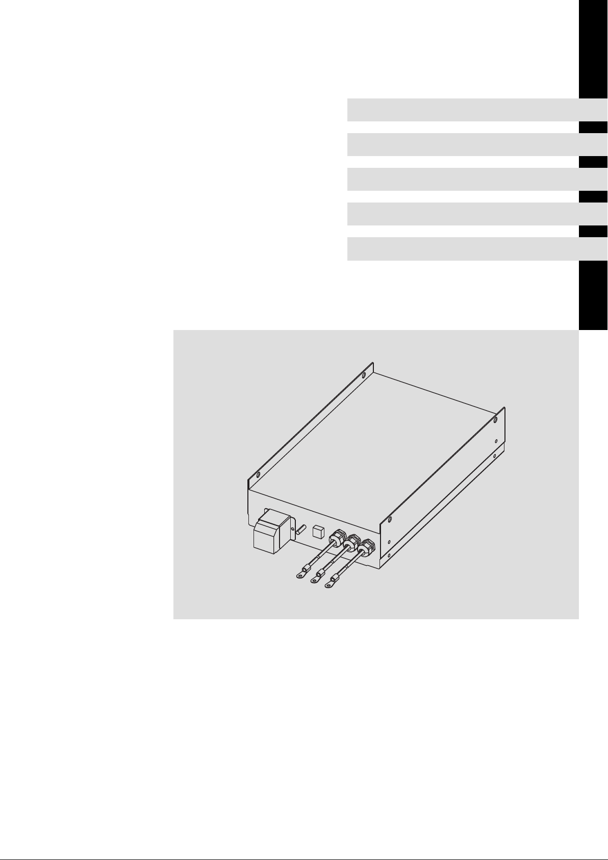
Global Drive 15 ... 90 A
Instructions de montage
E82ZZxxxxxB230 / E82ZNxxxxxB230
Unterbau−Filter
Footprint filter
Filtre montage arrière
l
Page 2

, Lesen Sie zuerst diese Anleitung und die Dokumentation zum Grundgerät, bevor Sie mit
den Arbeiten beginnen!
Beachten Sie die enthaltenen Sicherheitshinweise.
, Please read these instructions and the documentation of the standard device before you
start working!
Observe the safety instructions given therein!
, Lire le présent fascicule et la documentation relative à l’appareil de base avant toute
manipulation de l’équipement !
Respecter les consignes de sécurité fournies.
Page 3

Inhalt i
1 Über diese Dokumentation 4 . . . . . . . . . . . . . . . . . . . . . . . . . . . . . . . . . . . . . . . . . . . . . . . . .
1.1 Dokumenthistorie 4 . . . . . . . . . . . . . . . . . . . . . . . . . . . . . . . . . . . . . . . . . . . . . . . . . . . .
1.2 Verwendete Konventionen 5 . . . . . . . . . . . . . . . . . . . . . . . . . . . . . . . . . . . . . . . . . . . . .
1.3 Verwendete Hinweise 6 . . . . . . . . . . . . . . . . . . . . . . . . . . . . . . . . . . . . . . . . . . . . . . . . .
2 Sicherheitshinweise 7 . . . . . . . . . . . . . . . . . . . . . . . . . . . . . . . . . . . . . . . . . . . . . . . . . . . . . . . .
2.1 Restgefahren 7 . . . . . . . . . . . . . . . . . . . . . . . . . . . . . . . . . . . . . . . . . . . . . . . . . . . . . . . .
3 Produktbeschreibung 9 . . . . . . . . . . . . . . . . . . . . . . . . . . . . . . . . . . . . . . . . . . . . . . . . . . . . . .
4 Technische Daten 11 . . . . . . . . . . . . . . . . . . . . . . . . . . . . . . . . . . . . . . . . . . . . . . . . . . . . . . . . . .
4.1 Allgemeine Daten und Einsatzbedingungen 11 . . . . . . . . . . . . . . . . . . . . . . . . . . . . .
4.2 Bemessungsdaten 12 . . . . . . . . . . . . . . . . . . . . . . . . . . . . . . . . . . . . . . . . . . . . . . . . . . . .
4.3 Störspannungskategorie nach EN 61800−3 und Motorleitungslänge 13 . . . . . . . . . .
4.4 Mechanische Daten 15 . . . . . . . . . . . . . . . . . . . . . . . . . . . . . . . . . . . . . . . . . . . . . . . . .
5 Mechanische Installation 16 . . . . . . . . . . . . . . . . . . . . . . . . . . . . . . . . . . . . . . . . . . . . . . . . . . .
5.1 Wichtige Hinweise 16 . . . . . . . . . . . . . . . . . . . . . . . . . . . . . . . . . . . . . . . . . . . . . . . . . . . .
5.2 Montageschritte 17 . . . . . . . . . . . . . . . . . . . . . . . . . . . . . . . . . . . . . . . . . . . . . . . . . . . . .
6 Elektrische Installation 18 . . . . . . . . . . . . . . . . . . . . . . . . . . . . . . . . . . . . . . . . . . . . . . . . . . . . .
6.1 Wichtige Hinweise 18 . . . . . . . . . . . . . . . . . . . . . . . . . . . . . . . . . . . . . . . . . . . . . . . . . . . .
6.2 Anschlussplan 19 . . . . . . . . . . . . . . . . . . . . . . . . . . . . . . . . . . . . . . . . . . . . . . . . . . . . . . .
6.3 Anschlussdaten 19 . . . . . . . . . . . . . . . . . . . . . . . . . . . . . . . . . . . . . . . . . . . . . . . . . . . . . .
6.4 Verdrahtung 20 . . . . . . . . . . . . . . . . . . . . . . . . . . . . . . . . . . . . . . . . . . . . . . . . . . . . . . . . .
EDK82ZN903 DE/EN/FR 5.1
l 3
Page 4

1
Über diese Dokumentation
Dokumenthistorie
0Abb. 0Tab. 0
1 Über diese Dokumentation
Informationen zur Gültigkeit
Diese Anleitung ist gültig für
ƒ Netzfilter E82ZNxxxxxB230 (Funk−Entstörfilter und Netzdrossel)
ƒ Funk−Entstörfilter E82ZZxxxxxB230 (ohne Netzdrossel)
Zielgruppe
Diese Dokumentation richtet sich an qualifiziertes Fachpersonal nach IEC 364.
Qualifiziertes Fachpersonal sind Personen, die für die auszuführenden Tätigkeiten bei der
Aufstellung, Montage, Inbetriebsetzung und dem Betrieb des Produkts über entsprechende Qualifikationen verfügen.
I Tipp!
Dokumentationen und Software−Updates zu weiteren Lenze Produkten finden
Sie im Internet im Bereich "Services & Downloads" unter
http://www.Lenze.com
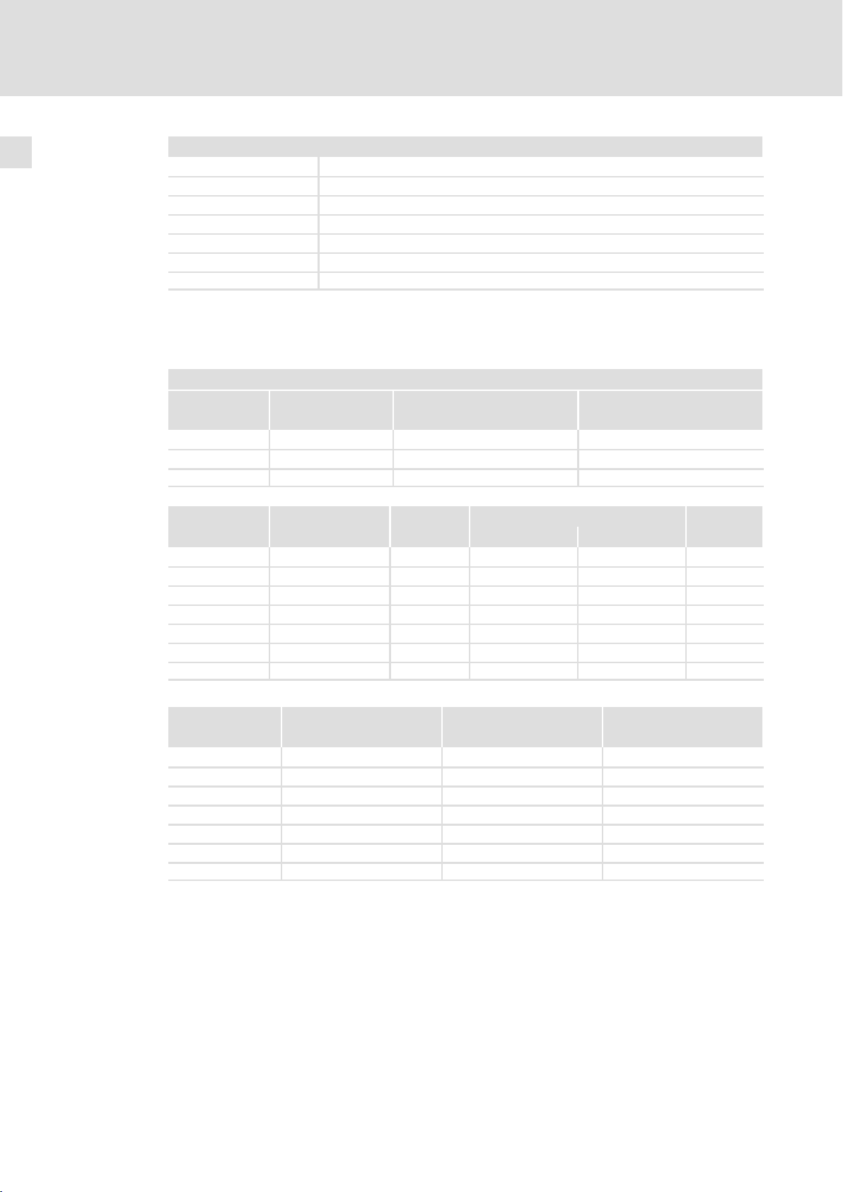
1.1 Dokumenthistorie
Materialnummer Version Beschreibung
!N@Y 1.0 08/2002 TD16 Erstausgabe
!P~} 1.1 11/2003 TD15 Überarbeitung
.$Xk 2.0 03/2005 TD29 Überarbeitung
.588 3.0 04/2007 TD00 Überarbeitung
.6_5 4.0 08/2007 TD29 Überarbeitung
.A,= 5.0 11/2009 TD29 Überarbeitung
.A,= 5.1 07/2010 TD29 Neuauflage wegen Neuorganisation des Unterneh-
mens
4
l
EDK82ZN903 DE/EN/FR 5.1
Page 5
Über diese Dokumentation
Verwendete Konventionen
1
1.2 Verwendete Konventionen
Informationsart Auszeichnung Beispiele/Hinweise
Zahlenschreibweise
Dezimaltrennzeichen
Warnhinweise
UL−Warnhinweise
UR−Warnhinweise
Textauszeichnung
Programmname » « PC−Software
Symbole
Seitenverweis ^ Verweis auf eine andere Seite mit zusätzli-
Punkt Es wird generell der Dezimalpunkt verwen-
J
O
det.
Zum Beispiel: 1234.56
Werden nur in der englischen Sprache verwendet.
Zum Beispiel: »Engineer«
chen Informationen
Zum Beispiel: ^ 16 = siehe Seite 16
EDK82ZN903 DE/EN/FR 5.1
l
5
Page 6

1
Über diese Dokumentation
Verwendete Hinweise
1.3 Verwendete Hinweise
Um auf Gefahren und wichtige Informationen hinzuweisen, werden in dieser Dokumentation folgende Piktogramme und Signalwörter verwendet:
Sicherheitshinweise
Aufbau der Sicherheitshinweise:
} Gefahr!
(kennzeichnet die Art und die Schwere der Gefahr)
Hinweistext
(beschreibt die Gefahr und gibt Hinweise, wie sie vermieden werden kann)
Piktogramm und Signalwort Bedeutung
{ Gefahr!
} Gefahr!
( Stop!
Gefahr von Personenschäden durch gefährliche elektrische
Spannung
Hinweis auf eine unmittelbar drohende Gefahr, die den Tod oder
schwere Verletzungen zur Folge haben kann, wenn nicht die
entsprechenden Maßnahmen getroffen werden.
Gefahr von Personenschäden durch eine allgemeine Gefahrenquelle
Hinweis auf eine unmittelbar drohende Gefahr, die den Tod oder
schwere Verletzungen zur Folge haben kann, wenn nicht die
entsprechenden Maßnahmen getroffen werden.
Gefahr von Sachschäden
Hinweis auf eine mögliche Gefahr, die Sachschäden zur Folge
haben kann, wenn nicht die entsprechenden Maßnahmen getroffen werden.
Anwendungshinweise
Piktogramm und Signalwort Bedeutung
) Hinweis!
I Tipp!
,
Wichtiger Hinweis für die störungsfreie Funktion
Nützlicher Tipp für die einfache Handhabung
Verweis auf andere Dokumentation
6
l
EDK82ZN903 DE/EN/FR 5.1
Page 7

2 Sicherheitshinweise
2.1 Restgefahren
{ Gefahr!
Gefährliche elektrische Spannung
Alle Leistungsanschlüsse führen bis zu 3 Minuten nach Netz−Ausschalten
gefährliche elektrische Spannung.
Mögliche Folgen:
ƒ Tod oder schwere Verletzungen beim Berühren der Leistungsanschlüsse.
Schutzmaßnahmen:
ƒ Vor Arbeiten an den Leistungsanschlüssen Netz abschalten und mindestens
3 Minuten warten.
ƒ Prüfen, ob alle Leistungsanschlüsse spannungsfrei sind.
Sicherheitshinweise
Restgefahren
2
{ Gefahr!
Gefährliche elektrische Spannung
Der Ableitstrom gegen Erde (PE) ist > 3.5 mA AC bzw. > 10 mA DC.
Mögliche Folgen:
ƒ Tod oder schwere Verletzungen beim Berühren des Gerätes im Fehlerfall.
Schutzmaßnahmen:
ƒ Die in der EN 61800−5−1 geforderten Maßnahmen umsetzen. Insbesondere:
– Festinstallation
– PE−Anschluss normgerecht ausführen (PE−Leiterdurchmesser ³ 10 mm
oder PE−Leiter doppelt auflegen)
( Stop!
Kein Geräteschutz gegen zu hohe Netzspannung
Der Netzeingang ist intern nicht abgesichert.
Mögliche Folgen:
ƒ Zerstörung des Gerätes bei zu hoher Netzspannung.
Schutzmaßnahmen:
ƒ Beachten Sie die maximal zulässige Netzspannung.
ƒ Sichern Sie das Gerät netzseitig fachgerecht gegen Netzschwankungen und
Spannungsspitzen ab.
2
EDK82ZN903 DE/EN/FR 5.1
l
7
Page 8

2
Sicherheitshinweise
Restgefahren
( Stop!
Hohes Gerätegewicht
Das Gerät ist sehr schwer und muss für die Montage angehoben werden.
Mögliche Folgen:
ƒ Personenschäden, insbesondere Rückenschäden beim Anheben bzw. Halten
des Gerätes
ƒ Sach− und Personenschäden durch Herunterfallen des Gerätes
Schutzmaßnahmen:
ƒ Gerät nur mit einer für das Gerätegewicht zugelassenen
Lastaufnahmeeinrichtung (z. B. Hallenkran) transportieren.
ƒ Hebezeug, Lastaufnahmeeinrichtung und Anschlagmittel vor dem Transport
auf ausreichende Tragfähigkeit und einwandfreien Zustand prüfen.
ƒ Hebezeug und Anschlagmittel erst entfernen, wenn das Gerät sicher auf
einem tragfähigen Untergrund aufliegt oder endgültig montiert ist.
O Warnings!
Conditions of Acceptability:
ƒ The products covered by this report are intended for use with Power
Conversion Equipment (inverters) only.
ƒ Appropriate cooling measures shall be taken based on the power loss data
within the instructions available from the manufacturer.
ƒ In the end−use application the wiring leads shall be protected from strain
relief and push back forces, mechanical damage and be routed away from
sharp edges, screw threads and the like, that can abrade the wire insulation.
8
l
EDK82ZN903 DE/EN/FR 5.1
Page 9
3 Produktbeschreibung
Lieferumfang
Anzahl Beschreibung
1 Filter
1 Montageanleitung
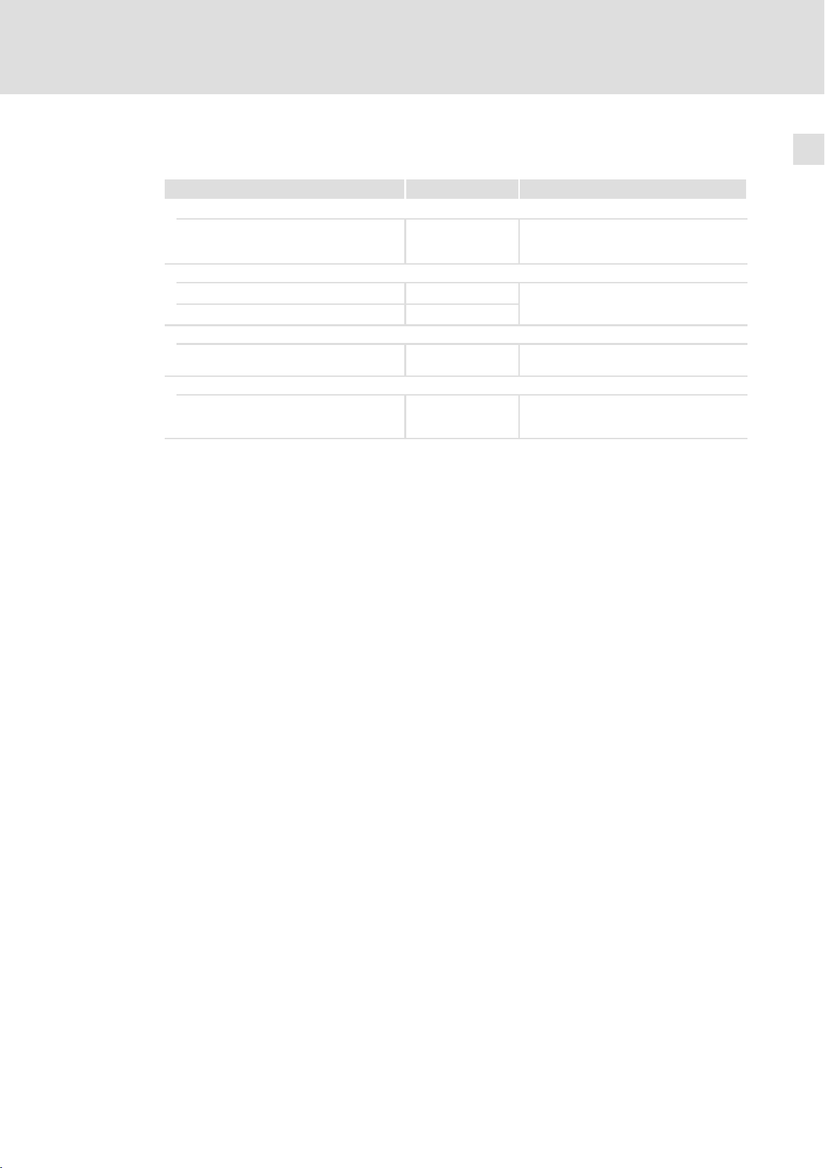
Elemente am Filter
Produktbeschreibung 3
2
Line
0
1
Load
8200vec081
Position Beschreibung
"Line" Netzanschluss (L1 ... L3)
0 PE−Gewindebolzen für Ring− oder Gabelkabelschuh
1 Anschluss Thermokontakt
"Load" Anschluss Grundgerät (L1’ ... L3’)
2
Typenschild
Einsatzbereich
Die Filter sind
ƒ für den Einsatz mit Frequenzumrichtern der Reihen 8200 vector, 9300 vector und
9300servo bestimmt (¶ 13).
ƒ für die Unterbaumontage an diesen Frequenzumrichtern vorgesehen.
EDK82ZN903 DE/EN/FR 5.1
l
9
Page 10
Produktbeschreibung3
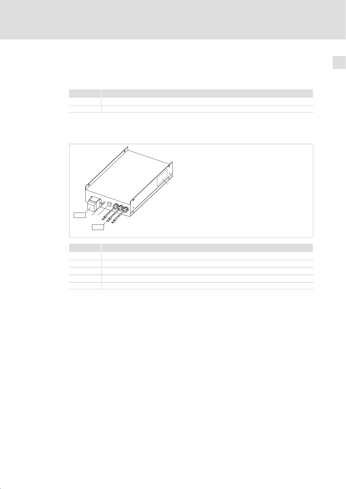
Identifikation
L
Type:
Abb. 3−1 Typenschild
Typenschlüssel
Produktreihe
Zubehör
Filtertyp
N = Netzfilter
Z = Funk−Entstörfilter
Leistung
z. B. 153 = 15 x 10
Anzahl Phasen
3 = 3 Phasen
Hans-Lenze-Straße 1
D-31855 Aerzen
3
W = 15 kW
Made in Germany
8200vec080
E82 Z x xxx 3 4 B 230
Spannungsklasse
4 = 400/500 V
Gerätegeneration
Filter−Variante
10
l
EDK82ZN903 DE/EN/FR 5.1
Page 11

Allgemeine Daten und Einsatzbedingungen
4 Technische Daten
4.1 Allgemeine Daten und Einsatzbedingungen
Normen
Approbation UL UL 508, Standard for Electromagnetic Interference Filters
Angaben zu Netzen
Netzformen
mit geerdetem Y−Punkt (TT−/TN−Netze)
ohne geerdetem Y−Punkt Max. Netzspannung 400 V!
IT−Netze Betrieb nicht zulässig
(File No. E219022) for USA and Canada
uneingeschränkte Nutzung
Anweisungen über besondere Maßnahmen in der Dokumentation zum Grundgerät beachten!
Technische Daten
4
Schutz
Schutzart
Isolationsfestigkeit EN 61800−5−1 Überspannungskategorie III
Ableitstrom EN 61800−5−1 > 3.5 mA Bestimmungen und
Schutzeinrichtung
Art Thermokontakt, potentialfreier
Funktion Überwachung der Geräte−Innen-
Schaltschwelle 140 °C
Schaltleistung 250 V / 1.6 A
Umweltbedingungen
Temperatur
Lagerung
Transport −25 ... +70 °C
Betrieb −10 ... +55 °C
Aufstellhöhe 0 ... 4000 m üNN
Verschmutzung EN 61800−5−1 Verschmutzungsgrad 2
Rüttelfestigkeit EN50178;
EN 60529
NEMA 250 Berührschutz nach Typ 1
IEC61800−5−1; Germanischer Loyd, allgemeine Bedingungen
IP 20
Reduzierung ab 2000 m: Überspannungskategorie II
Öffner
temperatur
−25 ... +60 °C
Stromreduzierung von +40 ... +55 °C: 2.5 %/°C
1000 ... 4000 m üNN: Stromreduzierung 5 %/1000 m
Beschleunigungsfest bis 0.7 g
nicht im Anschlussbereich
der Klemmen
Sicherheitshinweise
beachten!
EDK82ZN903 DE/EN/FR 5.1
l
11
Page 12
4
Technische Daten
Bemessungsdaten
Montagebedingungen
Montageort im Schaltschrank
Montageposition zwischen Montageplatte und Grundgerät
Einbaulage senkrecht, Anschlüsse oben
Einbaufreiräume
oben > 150 mm
unten > 100 mm
seitlich > 50 mm
4.2 Bemessungsdaten
Grundlage der Daten
Netz Spannung Spannungsbereich Frequenzbereich
3/PE AC 400 320 − 0 % ... 440 + 0 % 45 ... 65
3/PE AC 480 432 − 0 % ... 528 + 0 % 45 ... 65
3/PE AC 500 450 − 0 % ... 550 + 0 % 45 ... 65
U
[V] U
LN
[V] f [Hz]
LN
Spannung Frequenz Strom [A]
[V] [Hz] bis +45 °C bis +55 °C
E82ZZ15334B... 400/480/500 50/60 43/43/43 26.8/26.8/26.8 3
E82ZN22334B... 400/480/500 50/60 42/42/42 26.3/26.3/26.3 3
E82ZN30334B... 400/480/500 50/60 55/55/55 34.3/34.3/34.3 3
E82ZN45334B... 400/480/500 50/60 80/80/80 50.0/50.0/50.0 3
E82ZN55334B... 400/480/500 50/60 100/100/100 62.5/62.5/62.5 3
E82ZN75334B... 400/480/500 50/60 135/135/135 84.3/84.3/84.3 3
E82ZN90334B... 400/480/500 50/60 165/165/165 103/103/103 3
Temperatur im Schaltschrank
Verlustleistung Induktivität Spannungsabfall
PV [W] L [mH] DU [V]
E82ZZ15334B... 50 − −
E82ZN22334B... 100 0.70 9
E82ZN30334B... 200 0.47 10
E82ZN45334B... 200 0.35 10
E82ZN55334B... 400 0.30 10
E82ZN75334B... 200 0.15 7
E82ZN90334B... 350 0.15 9
Phasenzahl
12
l
EDK82ZN903 DE/EN/FR 5.1
Page 13
Technische Daten
Störspannungskategorie nach EN 61800−3 und Motorleitungslänge
4
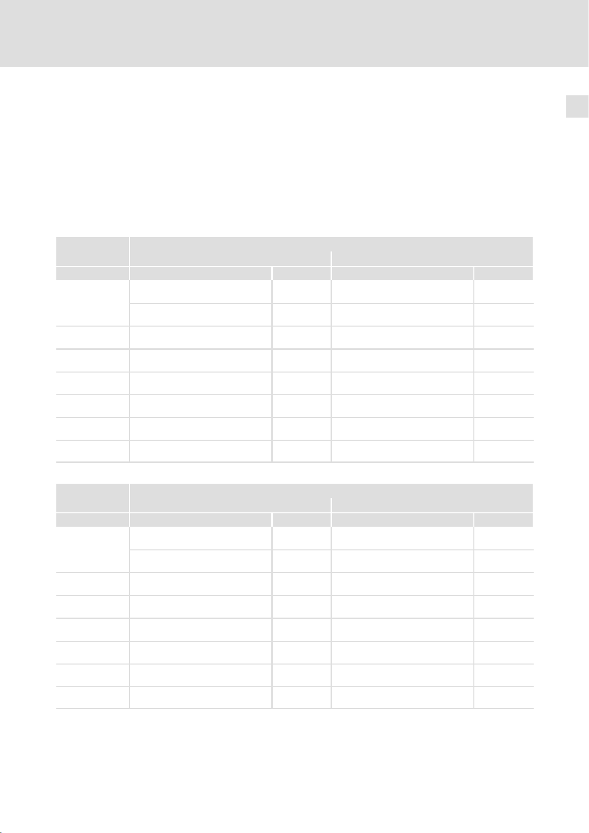
4.3 Störspannungskategorie nach EN 61800−3 und Motorleitungslänge
Die Grenzwerte der leitungsgebundenen Störaussendungen nach EN 61800−3 (Kategorie C2 oder Kategorie C1) werden eingehalten, wenn folgende Bedingungen erfüllt sind:
ƒ Vorgegebene zulässige Motorleitungslänge einhalten.
ƒ Kapazitätsarme Motorleitungen verwenden.
ƒ Filter E82ZZ... bzw. E82ZN... einsetzen.
Betrieb mit Bemessungsleistung (Normalbetrieb)
8200 vector
Typ C2 max. [m] C1 max. [m]
E82EV153K4B2xx E82ZN22334B230 50
E82ZZ15334B230 50
E82EV223K4B2xx E82ZN22334B230 50
E82EV303K4B2xx E82ZN30334B230 50
E82EV453K4B2xx E82ZN45334B230 50
E82EV553K4B2xx E82ZN55334B230 50
E82EV753K4B2xx E82ZN75334B230 50
E82EV903K4B2xx E82ZN90334B230 50
5)
bei Schaltfrequenz f
Störspannungskategorie nach EN 61800−3 und Motorleitungslänge
Komponente Komponente
5)
10
5)
10
5)
10
5)
10
5)
10
5)
10
5)
10
5)
10
= 16 kHz; die Störspannungskategorie C1 kann nicht eingehalten werden
ch
E82ZN22334B230 10
E82ZZ15334B230 10
E82ZN22334B230 10
E82ZN30334B230 10
E82ZN45334B230 10
E82ZN55334B230 10
E82ZN75334B230 10
E82ZN90334B230 10
5)
0
5)
0
5)
0
5)
0
5)
0
5)
0
5)
0
5)
0
9300 vector
Störspannungskategorie nach EN 61800−3 und Motorleitungslänge
Komponente Komponente
Typ C2 max. [m] C1 max. [m]
EVF9327−EV
EVF9328−EV E82ZN22334B230 50
EVF9329−EV E82ZN30334B230 50
EVF9330−EV E82ZN45334B230 50
EVF9331−EV E82ZN55334B230 50
EVF9332−EV E82ZN75334B230 50
EVF9333−EV E82ZN90334B230 25
5)
bei Schaltfrequenz f
E82ZN22334B230
10
E82ZZ15334B230 50
10
10
10
10
10
10
10
= 16 kHz; die Störspannungskategorie C1 kann nicht eingehalten werden
ch
50
5)
5)
5)
5)
5)
5)
5)
5)
E82ZN22334B230 10
0
E82ZZ15334B230 10
0
E82ZN22334B230 10
0
E82ZN30334B230 10
0
E82ZN45334B230 10
0
E82ZN55334B230 10
0
E82ZN75334B230 10
0
E82ZN90334B230 10
0
5)
5)
5)
5)
5)
5)
5)
5)
EDK82ZN903 DE/EN/FR 5.1
l
13
Page 14
4
Technische Daten
Störspannungskategorie nach EN 61800−3 und Motorleitungslänge
9300 servo
Typ C2 max. [m] C1 max. [m]
EVS9327−Ex
E82ZN22334B230
E82ZZ15334B230 50
EVS9328−Ex E82ZN22334B230 50
EVS9329−Ex E82ZN30334B230 50
EVS9330−Ex E82ZN55334B230 50
EVS9331−Ex E82ZN75334B230 50
EVS9332−Ex E82ZN75334B230 50
5)
bei Schaltfrequenz f
Störspannungskategorie nach EN 61800−3 und Motorleitungslänge
Komponente Komponente
50
5)
10
5)
10
5)
10
5)
10
5)
10
5)
10
5)
10
= 16 kHz; die Störspannungskategorie C1 kann nicht eingehalten werden
ch
E82ZN22334B230 10
E82ZZ15334B230 10
E82ZN22334B230 10
E82ZN30334B230 10
− −
E82ZN75334B230 10
E82ZN75334B230 10
5)
0
5)
0
5)
0
5)
0
5)
0
5)
0
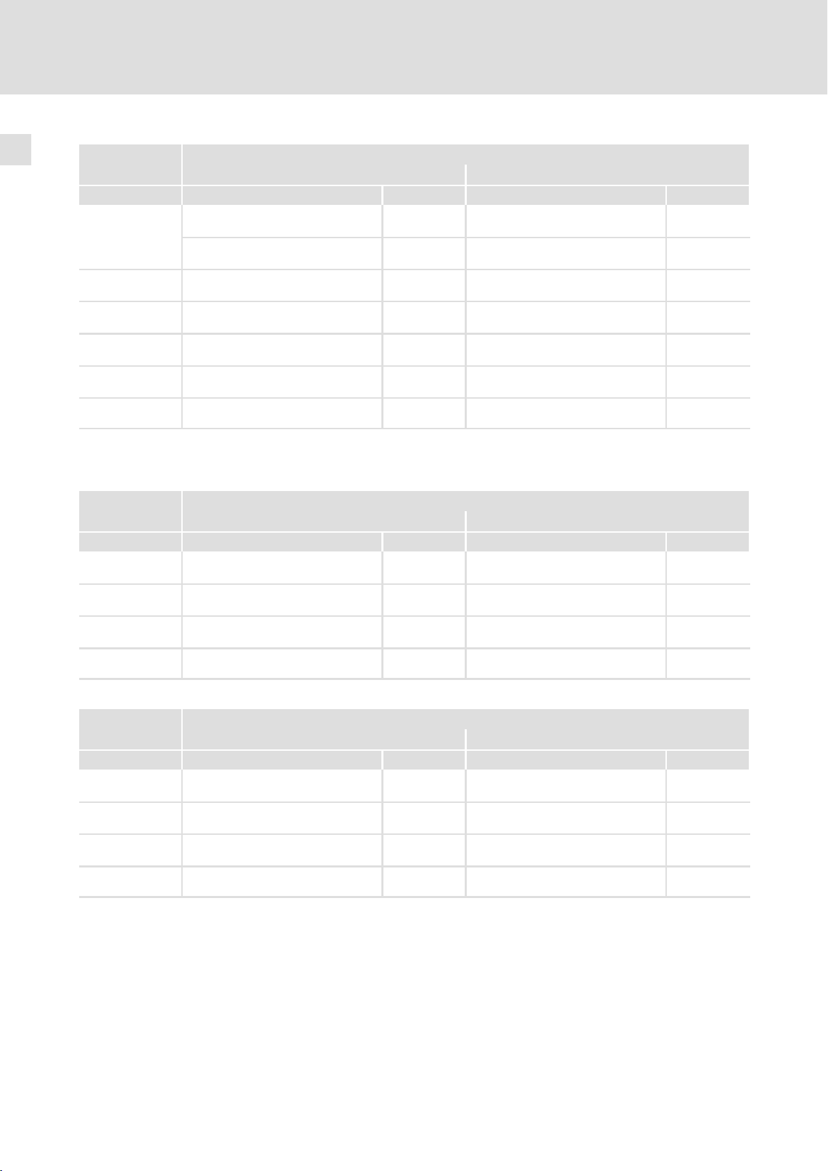
Betrieb mit erhöhter Bemessungsleistung
8200 vector
Typ C2 max. [m] C1 max. [m]
E82EV153K4B2xx E82ZN22334B230 50
E82EV223K4B2xx E82ZN30334B230 50
E82EV453K4B2xx E82ZN55334B230 50
E82EV753K4B2xx E82ZN90334B230 50
5)
bei Schaltfrequenz f
9300 vector
Typ C2 max. [m] C1 max. [m]
EVF9327−EV E82ZN22334B230 50
EVF9328−EV E82ZN30334B230 50
EVF9330−EV E82ZN55334B230 50
EVF9332−EV E82ZN90334B230 50
5)
bei Schaltfrequenz f
Störspannungskategorie nach EN 61800−3 und Motorleitungslänge
Komponente Komponente
5)
10
5)
10
5)
10
5)
10
= 16 kHz; die Störspannungskategorie C1 kann nicht eingehalten werden
ch
E82ZN22334B230 10
E82ZN30334B230 10
E82ZN55334B230 10
E82ZN90334B230 10
Störspannungskategorie nach EN 61800−3 und Motorleitungslänge
Komponente Komponente
5)
10
5)
10
5)
10
5)
10
= 16 kHz; die Störspannungskategorie C1 kann nicht eingehalten werden
ch
E82ZN22334B230 10
E82ZN30334B230 10
E82ZN55334B230 10
E82ZN90334B230 10
5)
0
5)
0
5)
0
5)
0
5)
0
5)
0
5)
0
5)
0
14
l
EDK82ZN903 DE/EN/FR 5.1
Page 15
Technische Daten
Mechanische Daten
4
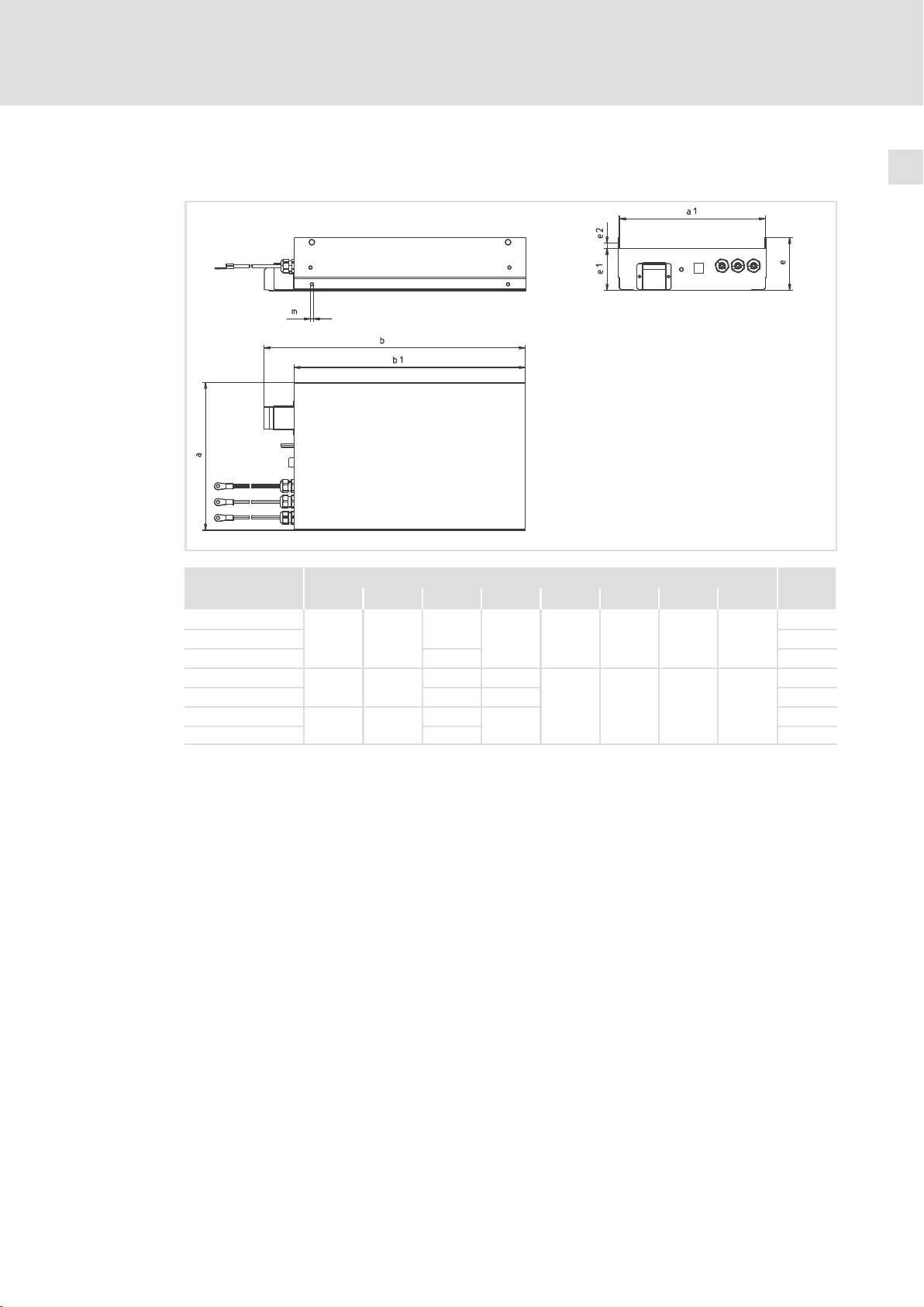
4.4 Mechanische Daten
Typ
a a1 b b1 e e1 e2 m [kg]
E82ZZ15334B230
E82ZN22334B230
E82ZN30334B230
E82ZN45334B230
E82ZN55334B230
E82ZN75334B230
E82ZN90334B230
235.5
318 313.5
428 423.5
231
8200vec103
Maße [mm] Masse
410
430 19
580 500
685 590 29
760
765 53
350 110 90 11.5 M5
114 90 14.5 M8
670
13
26
53
6
EDK82ZN903 DE/EN/FR 5.1
l
15
Page 16

5
Mechanische Installation
Wichtige Hinweise
5 Mechanische Installation
5.1 Wichtige Hinweise
ƒ Der Montageort muss den in den Technischen Daten genannten
Einsatzbedingungen immer entsprechen (¶ 11). Ggf. zusätzliche Maßnahmen
ergreifen.
ƒ Die Montageplatte des Schaltschranks muss folgende Eigenschaften aufweisen:
– elektrisch leitfähig
– lackfrei
ƒ Die mechanischen Verbindungen müssen immer gewährleistet sein.
( Stop!
Hohes Gerätegewicht
Das Gerät ist sehr schwer und muss für die Montage angehoben werden.
Mögliche Folgen:
ƒ Personenschäden, insbesondere Rückenschäden beim Anheben bzw. Halten
des Gerätes
ƒ Sach− und Personenschäden durch Herunterfallen des Gerätes
Schutzmaßnahmen:
ƒ Gerät nur mit einer für das Gerätegewicht zugelassenen
Lastaufnahmeeinrichtung (z. B. Hallenkran) transportieren.
ƒ Hebezeug, Lastaufnahmeeinrichtung und Anschlagmittel vor dem Transport
auf ausreichende Tragfähigkeit und einwandfreien Zustand prüfen.
ƒ Hebezeug und Anschlagmittel erst entfernen, wenn das Gerät sicher auf
einem tragfähigen Untergrund aufliegt oder endgültig montiert ist.
16
l
EDK82ZN903 DE/EN/FR 5.1
Page 17
Mechanische Installation
Montageschritte
5
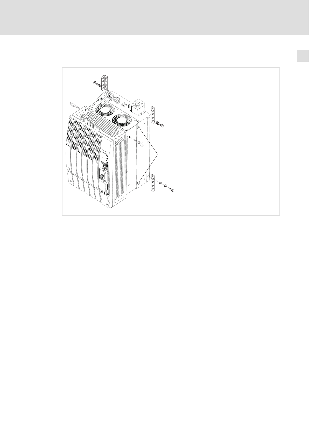
5.2 Montageschritte
0
0
L
1
0
0 Befestigungswinkel (im Lieferumfang des Grundgerätes)
1 Verschraubung Grundgerät mit Filter
So montieren Sie das Filter:
1. Lesen Sie in der Dokumentation des Grundgerätes das Kapitel "Mechanische
Installation". Informieren Sie sich insbesondere über ...
– Vorsichtsmaßnahmen während der Montage
– das benötigte Montagematerial
– die vorgeschriebenen Anzugsmomente
– die Bohrabstände und Einbaufreiräume
2. Vier Befestigungswinkel 0 am Filter montieren
3. Grundgerät auf waagerecht liegendes Filter setzen und mit 4 Schrauben 1
verschrauben.
4. Montageplatte gemäß Bohrplan vorbereiten.
5. Grundgerät mit Filter im Schaltschrank montieren.
8200vec105
EDK82ZN903 DE/EN/FR 5.1
l
17
Page 18

6
Elektrische Installation
Wichtige Hinweise
6 Elektrische Installation
6.1 Wichtige Hinweise
ƒ Die Installation muss
– den in den Technischen Daten genannten Einsatzbedingungen immer
entsprechen (¶ 11).
– nach EN 60204−1 ausgeführt werden.
ƒ Bei der Auswahl des Leitungstyps beachten:
– Die verwendeten Leitungen müssen den geforderten Approbationen am
Einsatzort entsprechen (z. B. VDE, UL usw.).
– Absicherung und Leitungsquerschnitte gemäß den Vorgaben in der
Dokumentation zum Grundgerät bemessen.
18
l
EDK82ZN903 DE/EN/FR 5.1
Page 19

Elektrische Installation
Anschlussplan
6
6.2 Anschlussplan
K1
L1
L2
L3
N
PE
8200 vector
9300 vector
9300 servo
4 Thermokontakt so in die Anlagenüberwachung einbinden, dass bei Überhitzung des Filters die Netzversorgung
abgeschalten wird.
6.3 Anschlussdaten
Load
J >
4
L1L1 L2L2 T1
PEPE
F1...F3
L3L3 T2
Line
E82ZZ...
E82ZN...
8200vec107
Typ
E82ZZ15334B230
E82ZN22334B230
E82ZN30334B230
E82ZN45334B230
E82ZN55334B230
E82ZN75334B230
E82ZN90334B230
Typ
E82ZZ15334B230
E82ZN22334B230
E82ZN30334B230
E82ZN45334B230
E82ZN55334B230
E82ZN75334B230
E82ZN90334B230
"Line"
(Klemmen L1/L2/L3)
max. Leiterquerschnitt Anzugsmoment Æ Anzugsmoment
[mm2] [AWG] [Nm] [lb−in] [Nm] [lb−in]
16
35 2 2 ... 5 17.7 ... 44.3
50 1/0 2 ... 6 17.7 ... 53.1
95 4/0
95 4/0
120 250 10 ... 20 88.5 ... 177
Temperatur−Schalter (Klemmen T1/T2) PE (Gewindebolzen)
max. Leiterquerschnitt Anzugsmoment Æ Anzugsmoment
[mm2] [AWG] [Nm] [lb−in] [Nm] [lb−in]
4
6 2 ... 4 17.7 ... 35.4
6 ... 12 53.1 ... 106.2
28 ... 10 0.6 ... 0.8 5.3 ... 7.1
(Leitungen mit Ringkabelschuh)
M6
M8
M10
M6 5 44.3
M8 12 106.2
M10 23 203.6
"Load"
siehe Dokumentation
zum Grundgerät
EDK82ZN903 DE/EN/FR 5.1
l
19
Page 20

6
Elektrische Installation
Verdrahtung
6.4 Verdrahtung
( Stop!
ƒ Bei der Verdrahtung die Montageanleitung des Grundgerätes beachten.
ƒ Die elektrischen Verbindungen müssen dauerhaft gewährleistet sein.
L
0
1
2
3
0 Anschlussleitungen "Load"
1 Schraubklemmen "Temperatur−Schalter"
2 PE−Gewindebolzen
3 Schraubklemmen "Line"
So verdrahten Sie das Filter:
1. Anschlussleitungen "Load" 0 am Grundgerät anschließen.
– Montageanleitung des Grundgerätes beachten!
2. Klemmen des Temperatur−Schalters 1 verdrahten.
– Anzugsmoment beachten!
– Schaltleistung: 250 V AC / 1,6 A (Öffner)
– Den Thermokontakt so in die Anlagenüberwachung einbinden, dass bei
Überhitzung des Filters die Netzversorgung abgeschaltet wird.
3. PE−Leiter mit Ringkabelschuh an PE−Gewindebolzen 2 montieren.
– Anzugsmoment beachten!
4. Netzleitungen an Schraubklemme "Line" 2 anschließen.
– Anzugsmoment beachten!
8200vec106
20
l
EDK82ZN903 DE/EN/FR 5.1
Page 21

Contents i
1 About this documentation 22 . . . . . . . . . . . . . . . . . . . . . . . . . . . . . . . . . . . . . . . . . . . . . . . . . .
1.1 Document history 22 . . . . . . . . . . . . . . . . . . . . . . . . . . . . . . . . . . . . . . . . . . . . . . . . . . . .
1.2 Conventions used 23 . . . . . . . . . . . . . . . . . . . . . . . . . . . . . . . . . . . . . . . . . . . . . . . . . . . .
1.3 Notes used 24 . . . . . . . . . . . . . . . . . . . . . . . . . . . . . . . . . . . . . . . . . . . . . . . . . . . . . . . . . .
2 Safety instructions 25 . . . . . . . . . . . . . . . . . . . . . . . . . . . . . . . . . . . . . . . . . . . . . . . . . . . . . . . . .
2.1 Residual hazards 25 . . . . . . . . . . . . . . . . . . . . . . . . . . . . . . . . . . . . . . . . . . . . . . . . . . . . .
3 Product description 27 . . . . . . . . . . . . . . . . . . . . . . . . . . . . . . . . . . . . . . . . . . . . . . . . . . . . . . . .
4 Technical data 29 . . . . . . . . . . . . . . . . . . . . . . . . . . . . . . . . . . . . . . . . . . . . . . . . . . . . . . . . . . . .
4.1 General data and operating conditions 29 . . . . . . . . . . . . . . . . . . . . . . . . . . . . . . . . .
4.2 Rated data 30 . . . . . . . . . . . . . . . . . . . . . . . . . . . . . . . . . . . . . . . . . . . . . . . . . . . . . . . . . .
4.3 Interference voltage category according to EN 61800−3 and motor cable length 31
4.4 Mechanical data 33 . . . . . . . . . . . . . . . . . . . . . . . . . . . . . . . . . . . . . . . . . . . . . . . . . . . .
5 Mechanical installation 34 . . . . . . . . . . . . . . . . . . . . . . . . . . . . . . . . . . . . . . . . . . . . . . . . . . . . .
5.1 Important notes 34 . . . . . . . . . . . . . . . . . . . . . . . . . . . . . . . . . . . . . . . . . . . . . . . . . . . . . .
5.2 Mounting steps 35 . . . . . . . . . . . . . . . . . . . . . . . . . . . . . . . . . . . . . . . . . . . . . . . . . . . . . .
6 Electrical installation 36 . . . . . . . . . . . . . . . . . . . . . . . . . . . . . . . . . . . . . . . . . . . . . . . . . . . . . . .
6.1 Important notes 36 . . . . . . . . . . . . . . . . . . . . . . . . . . . . . . . . . . . . . . . . . . . . . . . . . . . . . .
6.2 Connection plan 37 . . . . . . . . . . . . . . . . . . . . . . . . . . . . . . . . . . . . . . . . . . . . . . . . . . . . . .
6.3 Connection data 37 . . . . . . . . . . . . . . . . . . . . . . . . . . . . . . . . . . . . . . . . . . . . . . . . . . . . .
6.4 Wiring 38 . . . . . . . . . . . . . . . . . . . . . . . . . . . . . . . . . . . . . . . . . . . . . . . . . . . . . . . . . . . . . .
EDK82ZN903 DE/EN/FR 5.1
l 21
Page 22

1
About this documentation
Document history
0Fig. 0Tab. 0
1 About this documentation
Validity information
These instructions are valid for
ƒ Mains filter E82ZNxxxxxB230 (RFI filter and mains choke)
ƒ RFI Filter E82ZZxxxxxB230 (without mains choke)
Target group
This documentation is intended for qualified personnel according to IEC 364.
Qualified, skilled personnel are persons who have the qualifications necessary for the work
activities to be undertaken during the assembly, installation, comissioning, and operation
of the product.
I Tip!
Documentation and software updates for further Lenze products can be found
on the Internet in the "Services & Downloads" area under
http://www.Lenze.com
1.1 Document history
Material number Version Description
!N@Y 1.0 08/2002 TD16 First edition
!P~} 1.1 11/2003 TD15 Revision
.$Xk 2.0 03/2005 TD29 Revision
588 3.0 04/2007 TD00 Revision
.6_5 4.0 08/2007 TD29 Revision
.A,= 5.0 11/2009 TD29 Revision
.A,= 5.1 07/2010 TD29 New edition due to reorganisation of the company
22
l
EDK82ZN903 DE/EN/FR 5.1
Page 23

About this documentation
Conventions used
1
1.2 Conventions used
Type of information Identification Examples/notes
Spelling of numbers
Decimal separator
Warnings
UL warnings
UR warnings
Text
Program name » « PC software
Icons
Page reference ^ Reference to another page with additional
Point In general, the decimal point is used.
For instance: 1234.56
J
O
Are only given in English.
For example: »Engineer«
information
For instance: ^ 16 = see page 16
EDK82ZN903 DE/EN/FR 5.1
l
23
Page 24

1
About this documentation
Notes used
1.3 Notes used
The following pictographs and signal words are used in this documentation to indicate
dangers and important information:
Safety instructions
Structure of safety instructions:
} Danger!
(characterises the type and severity of danger)
Note
(describes the danger and gives information about how to prevent dangerous
situations)
Pictograph and signal word Meaning
{ Danger!
} Danger!
( Stop!
Danger of personal injury through dangerous electrical voltage.
Reference to an imminent danger that may result in death or
serious personal injury if the corresponding measures are not
taken.
Danger of personal injury through a general source of danger.
Reference to an imminent danger that may result in death or
serious personal injury if the corresponding measures are not
taken.
Danger of property damage.
Reference to a possible danger that may result in property
damage if the corresponding measures are not taken.
Application notes
Pictograph and signal word Meaning
) Note!
I Tip!
,
Important note to ensure troublefree operation
Useful tip for simple handling
Reference to another documentation
24
l
EDK82ZN903 DE/EN/FR 5.1
Page 25

2 Safety instructions
2.1 Residual hazards
{ Danger!
Dangerous electrical voltage
All power terminals remain live for up to three minutes after mains
disconnection.
Possible consequences:
ƒ Death or severe injuries when touching the power terminals.
Protective measures:
ƒ Switch off the power supply and wait for at least three minutes before
working on the power terminals.
ƒ Make sure that all power terminals are deenergised.
Safety instructions
Residual hazards
2
{ Danger!
Dangerous voltage
The leakage current to earth (PE) is > 3.5 mA AC or > 10 mA DC.
Possible consequences:
ƒ Death or severe injuries when the device is touched in the event of a fault.
Protective measures:
ƒ Implement the actions required in the EN 61800−5−1. Especially:
– Fixed installation
– PE connection must conform to standards (PE conductor diameter
³ 10 mm
( Stop!
No device protection if the mains voltage is too high
The mains input is not internally fused.
Possible consequences:
ƒ Destruction of the device if the mains voltage is too high.
Protective measures:
ƒ Observe the maximally permissible mains voltage.
ƒ Fuse the device correctly on the supply side against mains fluctuations and
voltage peaks.
2
or PE conductor must be connected twice)
EDK82ZN903 DE/EN/FR 5.1
l
25
Page 26

2
Safety instructions
Residual hazards
( Stop!
Heavy device weight
The device is very heavy and must be lifted for the mounting.
Possible consequences:
ƒ Injury to persons, particularly backache when lifting and holding the device,
respectively
ƒ Injury to persons and damage to material assets due to the device falling
down
Protective measures:
ƒ The device must only be carried with a load bearing system such as an
indoor crane permitted for the device weight
ƒ Before the transport, the hoist, the load bearing system and lifting
accessories must be checked for sufficient payload and faultless status
ƒ Do not remove the hoist and the lifting accessories until the device lies safe
on a stable surface or is finally mounted.
O Warnings!
Conditions of Acceptability:
ƒ The products covered by this report are intended for use with Power
Conversion Equipment (inverters) only.
ƒ Appropriate cooling measures shall be taken based on the power loss data
within the instructions available from the manufacturer.
ƒ In the end−use application the wiring leads shall be protected from strain
relief and push back forces, mechanical damage and be routed away from
sharp edges, screw threads and the like, that can abrade the wire insulation.
26
l
EDK82ZN903 DE/EN/FR 5.1
Page 27

3 Product description
Scope of supply
Quantity Description
1 Filter
1 Mounting Instructions
Elements on the filter
Product description 3
2
Line
0
1
Load
Position Description
"Line" Mains connection (L1 ... L3)
0 PE stud for ring cable lug or fork−type cable lug
1 Connection of thermal contact
"Load" Connection of basic device (L1’ ... L3’)
2
Nameplate
Range of application
The filters are
ƒ designed for the application with frequency inverters of the 8200 vector, 9300
vector and 9300servo series (¶ 31).
ƒ intended for footprint mounting at these frequency converters.
8200vec081
EDK82ZN903 DE/EN/FR 5.1
l
27
Page 28

Product description3
Identification
L
Type:
Fig. 3−1 Nameplate
Type code
Product range
Accessories
Filter type
N = mains filter
Z = RFI filter
Power
e.g. 153 = 15 x 10
Number of phases
3 = 3 phases
Hans-Lenze-Straße 1
D-31855 Aerzen
3
W = 15 kW
Made in Germany
8200vec080
E82 Z x xxx 3 4 B 230
Voltage class
4 = 400/500 V
Version
Filter variant
28
l
EDK82ZN903 DE/EN/FR 5.1
Page 29

General data and operating conditions
4 Technical data
4.1 General data and operating conditions
Standards
Approval UL UL 508, Standard for Electromagnetic Interference Filters
Mains data
Mains types
With grounded neutral (TT/TN systems)
Without grounded neutral Max. mains voltage 400 V!
IT systems Operation is not permissible.
Technical data
(File No. E219022) for USA and Canada
Operation permitted without restrictions
Observe instructions for special measures in the
documentation for the basic device!
4
Protection
Type of protection
Insulation resistance EN 61800−5−1 Overvoltage category III
Leakage current EN 61800−5−1 > 3.5 mA Observe regulations and
Protective device
Type Thermal contact, potential−free
Function Monitoring the internal
Switching threshold 140 °C
Switching capacity 250 V / 1.6 A
Ambient conditions
Temperature
Storage
Transport −25 ... +70 °C
Operation −10 ... +55 °C
Site altitude 0 ... 4000 m amsl
Pollution EN 61800−5−1 Pollution degree 2
Vibration resistance EN 50178; IEC
EN 60529
NEMA 250 Protection against contact to
61800−5−1;
Germanischer Lloyd,
general conditions
IP 20
type 1
> 2000 m: Overvoltage category II
NC contact
temperature of the device
−25 ... +60 °C
Current derating from +40 to +55 °C: 2.5 %/°C
1000 ... 4000 m amsl: Current derating by 5 %/1000 m
Acceleration−resistant up to 0.7 g
Not in the wire range of
the terminals
safety instructions!
EDK82ZN903 DE/EN/FR 5.1
l
29
Page 30

4
Technical data
Rated data
Mounting conditions
Mounting location In the control cabinet
Mounting position between mounting plate and basic device
Mounting position Vertical, connections on top
Free spaces
at the top > 150 mm
at the bottom > 100 mm
to the sides > 50 mm
4.2 Rated data
Basis of the data
Mains Voltage Voltage range Frequency range
3/PE AC 400 320 − 0 % ... 440 + 0 % 45 ... 65
3/PE AC 480 432 − 0 % ... 528 + 0 % 45 ... 65
3/PE AC 500 450 − 0 % ... 550 + 0 % 45 ... 65
U
[V] U
LN
[V] f [Hz]
LN
Voltage Frequency Current [A]
[V] [Hz] max. +45 °C max. +55 °C
E82ZZ15334B... 400/480/500 50/60 43/43/43 26.8/26.8/26.8 3
E82ZN22334B... 400/480/500 50/60 42/42/42 26.3/26.3/26.3 3
E82ZN30334B... 400/480/500 50/60 55/55/55 34.3/34.3/34.3 3
E82ZN45334B... 400/480/500 50/60 80/80/80 50.0/50.0/50.0 3
E82ZN55334B... 400/480/500 50/60 100/100/100 62.5/62.5/62.5 3
E82ZN75334B... 400/480/500 50/60 135/135/135 84.3/84.3/84.3 3
E82ZN90334B... 400/480/500 50/60 165/165/165 103/103/103 3
Temperature in the control cabinet
Power loss Inductance Voltage drop
P
[W] L [mH] DU [V]
loss
E82ZZ15334B... 50 − −
E82ZN22334B... 100 0.70 9
E82ZN30334B... 200 0.47 10
E82ZN45334B... 200 0.35 10
E82ZN55334B... 400 0.30 10
E82ZN75334B... 200 0.15 7
E82ZN90334B... 350 0.15 9
Number of
phases
30
l
EDK82ZN903 DE/EN/FR 5.1
Page 31

Technical data
Interference voltage category according to EN 61800−3 and motor cable length
4
4.3 Interference voltage category according to EN 61800−3 and motor cable length
The limit values of the conducted noise emissions according to EN 61800 −3 (categories C2
or C1) are complied with if the following conditions are met:
ƒ Specified permissible motor cable length is not exceeded.
ƒ Low−capacitance motor cables are used.
ƒ Filters E82ZZ... or E82ZN... are installed.
Operation with rated power (normal operation)
8200 vector
Type C2 max. [m] C1 max. [m]
E82EV153K4B2xx E82ZN22334B230 50
E82EV223K4B2xx E82ZN22334B230 50
E82EV303K4B2xx E82ZN30334B230 50
E82EV453K4B2xx E82ZN45334B230 50
E82EV553K4B2xx E82ZN55334B230 50
E82EV753K4B2xx E82ZN75334B230 50
E82EV903K4B2xx E82ZN90334B230 50
5)
at switching frequency fch = 16 kHz; the interference voltage category C1 cannot be achieved
Interference voltage category according to EN 61800−3 and motor cable length
Component Componente
E82ZN22334B230 10
E82ZZ15334B230 10
E82ZN22334B230 10
E82ZN30334B230 10
E82ZN45334B230 10
E82ZN55334B230 10
E82ZN75334B230 10
E82ZN90334B230 10
10
E82ZZ15334B230 50
10
10
10
10
10
10
10
5)
5)
5)
5)
5)
5)
5)
5)
5)
0
5)
0
5)
0
5)
0
5)
0
5)
0
5)
0
5)
0
9300 vector
Interference voltage category according to EN 61800−3 and motor cable length
Component Componente
Type C2 max. [m] C1 max. [m]
EVF9327−EV
EVF9328−EV E82ZN22334B230 50
EVF9329−EV E82ZN30334B230 50
EVF9330−EV E82ZN45334B230 50
EVF9331−EV E82ZN55334B230 50
EVF9332−EV E82ZN75334B230 50
EVF9333−EV E82ZN90334B230 25
5)
at switching frequency fch = 16 kHz; the interference voltage category C1 cannot be achieved
E82ZN22334B230
10
E82ZZ15334B230 50
10
10
10
10
10
10
10
50
5)
5)
5)
5)
5)
5)
5)
5)
E82ZN22334B230 10
0
E82ZZ15334B230 10
0
E82ZN22334B230 10
0
E82ZN30334B230 10
0
E82ZN45334B230 10
0
E82ZN55334B230 10
0
E82ZN75334B230 10
0
E82ZN90334B230 10
0
5)
5)
5)
5)
5)
5)
5)
5)
EDK82ZN903 DE/EN/FR 5.1
l
31
Page 32

4
Technical data
Interference voltage category according to EN 61800−3 and motor cable length
9300 servo
Type C2 max. [m] C1 max. [m]
EVS9327−Ex
EVS9328−Ex E82ZN22334B230 50
EVS9329−Ex E82ZN30334B230 50
EVS9330−Ex E82ZN55334B230 50
EVS9331−Ex E82ZN75334B230 50
EVS9332−Ex E82ZN75334B230 50
5)
at switching frequency fch = 16 kHz; the interference voltage category C1 cannot be achieved
Interference voltage category according to EN 61800−3 and motor cable length
Component Componente
E82ZN22334B230
E82ZZ15334B230 50
10
10
10
10
10
10
10
50
5)
5)
5)
5)
5)
5)
5)
E82ZN22334B230 10
E82ZZ15334B230 10
E82ZN22334B230 10
E82ZN30334B230 10
− −
E82ZN75334B230 10
E82ZN75334B230 10
5)
0
5)
0
5)
0
5)
0
5)
0
5)
0
Operation with increased rated power
8200 vector
Type C2 max. [m] C1 max. [m]
E82EV153K4B2xx E82ZN22334B230 50
E82EV223K4B2xx E82ZN30334B230 50
E82EV453K4B2xx E82ZN55334B230 50
E82EV753K4B2xx E82ZN90334B230 50
5)
at switching frequency fch = 16 kHz; the interference voltage category C1 cannot be achieved
9300 vector
Type C2 max. [m] C1 max. [m]
EVF9327−EV E82ZN22334B230 50
EVF9328−EV E82ZN30334B230 50
EVF9330−EV E82ZN55334B230 50
EVF9332−EV E82ZN90334B230 50
5)
at switching frequency fch = 16 kHz; the interference voltage category C1 cannot be achieved
Interference voltage category according to EN 61800−3 and motor cable length
Component Componente
E82ZN22334B230 10
E82ZN30334B230 10
E82ZN55334B230 10
E82ZN90334B230 10
10
10
10
10
5)
5)
5)
5)
Interference voltage category according to EN 61800−3 and motor cable length
Component Componente
E82ZN22334B230 10
E82ZN30334B230 10
E82ZN55334B230 10
E82ZN90334B230 10
10
10
10
10
5)
5)
5)
5)
5)
0
5)
0
5)
0
5)
0
5)
0
5)
0
5)
0
5)
0
32
l
EDK82ZN903 DE/EN/FR 5.1
Page 33

Technical data
Mechanical data
4
4.4 Mechanical data
Type
E82ZZ15334B230
E82ZN22334B230
E82ZN30334B230
E82ZN45334B230
E82ZN55334B230
E82ZN75334B230
E82ZN90334B230
Dimensions [mm] Mass
a a1 b b1 e e1 e2 m [kg]
235.5
318 313.5
428 423.5
231
410
430 19
580 500
685 590 29
760
765 53
350 110 90 11.5 M5
114 90 14.5 M8
670
8200vec103
6
13
26
53
EDK82ZN903 DE/EN/FR 5.1
l
33
Page 34

5
Mechanical installation
Important notes
5 Mechanical installation
5.1 Important notes
ƒ The mounting location must always fulfill the operating conditions specified in the
Technical data. (¶ 29). If necessary, take additional measures.
ƒ The mounting plate of the control cabinet must be:
– electrically conductive
– free of lacquer
ƒ The mechanical connections must always be ensured.
( Stop!
Heavy device weight
The device is very heavy and must be lifted for the mounting.
Possible consequences:
ƒ Injury to persons, particularly backache when lifting and holding the device,
respectively
ƒ Injury to persons and damage to material assets due to the device falling
down
Protective measures:
ƒ The device must only be carried with a load bearing system such as an
indoor crane permitted for the device weight
ƒ Before the transport, the hoist, the load bearing system and lifting
accessories must be checked for sufficient payload and faultless status
ƒ Do not remove the hoist and the lifting accessories until the device lies safe
on a stable surface or is finally mounted.
34
l
EDK82ZN903 DE/EN/FR 5.1
Page 35

Mechanical installation
Mounting steps
5
5.2 Mounting steps
0
0
L
1
0
0 Fixing bracket (included in delivery of basic device)
1 Screwed connection of basic device with filter
How to mount the filter:
1. Read the chapter "Mechanical installation" in the documentation of the basic
device. Read up particularly on ...
– Precautionary measures while mounting
– Installation material required
– Compulsory starting torques
– Bore spacings and free spaces
2. Attach the four fixing brackets 0 to the filter
3. Place the basic device upon the horizontal lying filter and screw together with 4
screws 1.
4. Prepare the mounting plate as shown in the drilling pattern.
5. Install basic device with filter in the control cabinet.
8200vec105
EDK82ZN903 DE/EN/FR 5.1
l
35
Page 36

6
Electrical installation
Important notes
6 Electrical installation
6.1 Important notes
ƒ Installation must
– always be in accordance with the operating conditions specified in the Technical
data (¶ 29).
– be carried out to EN 60204−1.
ƒ Please observe the following when selecting the cable type:
– The cables used must comply with the approvals required for the application (e. g.
VDE, UL etc.).
– Fuses and cable cross−sections must be dimensioned in accordance with the
specifications in the documentation for the basic device.
36
l
EDK82ZN903 DE/EN/FR 5.1
Page 37

Electrical installation
Connection plan
6
6.2 Connection plan
K1
L1
L2
L3
N
PE
8200 vector
9300 vector
9300 servo
4 Integrate the thermal contact into the monitoring system so that the mains supply is switched off when the filter is
overheated.
6.3 Connection data
Load
J >
4
L1L1 L2L2 T1
PEPE
F1...F3
L3L3 T2
Line
E82ZZ...
E82ZN...
8200vec107
Type
E82ZZ15334B230
E82ZN22334B230
E82ZN30334B230
E82ZN45334B230
E82ZN55334B230
E82ZN75334B230
E82ZN90334B230
Type
E82ZZ15334B230
E82ZN22334B230
E82ZN30334B230
E82ZN45334B230
E82ZN55334B230
E82ZN75334B230
E82ZN90334B230
"Line"
(Terminals L1/L2/L3)
Max. conductor
cross−section
[mm2] [AWG] [Nm] [lb−in] [Nm] [lb−in]
16
35 2 2 ... 5 17.7 ... 44.3
50 1/0 2 ... 6 17.7 ... 53.1
95 4/0
95 4/0
120 250 10 ... 20 88.5 ... 177
Max. conductor
cross−section
[mm2] [AWG] [Nm] [lb−in] [Nm] [lb−in]
4
6 2 ... 4 17.7 ... 35.4
Thermostat (terminals T1/T2) PE (stud bolt)
28 ... 10 0.6 ... 0.8 5.3 ... 7.1
Tightening torque Æ Tightening torque
6 ... 12 53.1 ... 106.2
Tightening torque Æ Tightening torque
(Lines with ring cable lug)
M6
M8
M10
M6 5 44.3
M8 12 106.2
M10 23 203.6
"Load"
See documentation on
basic device
EDK82ZN903 DE/EN/FR 5.1
l
37
Page 38

6
Electrical installation
Wiring
6.4 Wiring
( Stop!
ƒ Observe the Mounting Instructions for the basic device when wiring the
mains filter.
ƒ Ensure permanent electrical connections.
0
1
2
3
L
0 Connection cables "load"
1 Screw terminals "thermostat"
2 PE stud
3 Screw terminals "line"
How to wire the filter:
1. Connect the connection cables "load" 0 to the basic device.
– Observe the Mounting Instructions for the basic device!
2. Wire the terminals of the thermostat 1.
– Observe tightening torque!
– Switching capacity: 250 V AC / 1.6 A (NC contact)
– Integrate the thermal contact into the monitoring system so that the mains supply
is switched off when the filter is overheated.
3. Attach the PE conductor to the PE stud 2 with the ring cable lug.
– Observe tightening torque!
4. Connect the mains cables to the screw terminal "line" 2.
– Observe tightening torque!
8200vec106
38
l
EDK82ZN903 DE/EN/FR 5.1
Page 39

Sommaire i
1 Présentation du document 40 . . . . . . . . . . . . . . . . . . . . . . . . . . . . . . . . . . . . . . . . . . . . . . . . . .
1.1 Historique du document 40 . . . . . . . . . . . . . . . . . . . . . . . . . . . . . . . . . . . . . . . . . . . . . . .
1.2 Conventions utilisées 41 . . . . . . . . . . . . . . . . . . . . . . . . . . . . . . . . . . . . . . . . . . . . . . . . .
1.3 Consignes utilisées 42 . . . . . . . . . . . . . . . . . . . . . . . . . . . . . . . . . . . . . . . . . . . . . . . . . . .
2 Consignes de sécurité 43 . . . . . . . . . . . . . . . . . . . . . . . . . . . . . . . . . . . . . . . . . . . . . . . . . . . . . .
2.1 Dangers résiduels 43 . . . . . . . . . . . . . . . . . . . . . . . . . . . . . . . . . . . . . . . . . . . . . . . . . . . .
3 Description du produit 45 . . . . . . . . . . . . . . . . . . . . . . . . . . . . . . . . . . . . . . . . . . . . . . . . . . . . .
4 Spécifications techniques 47 . . . . . . . . . . . . . . . . . . . . . . . . . . . . . . . . . . . . . . . . . . . . . . . . . .
4.1 Caractéristiques générales et conditions d’utilisation 47 . . . . . . . . . . . . . . . . . . . . .
4.2 Caractéristiques assignées 48 . . . . . . . . . . . . . . . . . . . . . . . . . . . . . . . . . . . . . . . . . . . . .
4.3 Catégorie de tension parasite selon EN 61800−3 et longueur du câble moteur 49 . .
4.4 Caractéristiques mécaniques 52 . . . . . . . . . . . . . . . . . . . . . . . . . . . . . . . . . . . . . . . . . .
5 Installation mécanique 53 . . . . . . . . . . . . . . . . . . . . . . . . . . . . . . . . . . . . . . . . . . . . . . . . . . . . .
5.1 Remarques importantes 53 . . . . . . . . . . . . . . . . . . . . . . . . . . . . . . . . . . . . . . . . . . . . . . .
5.2 Opérations de montage 54 . . . . . . . . . . . . . . . . . . . . . . . . . . . . . . . . . . . . . . . . . . . . . . .
6 Installation électrique 55 . . . . . . . . . . . . . . . . . . . . . . . . . . . . . . . . . . . . . . . . . . . . . . . . . . . . . .
6.1 Remarques importantes 55 . . . . . . . . . . . . . . . . . . . . . . . . . . . . . . . . . . . . . . . . . . . . . . .
6.2 Schéma de câblage 56 . . . . . . . . . . . . . . . . . . . . . . . . . . . . . . . . . . . . . . . . . . . . . . . . . . .
6.3 Données de raccordement 56 . . . . . . . . . . . . . . . . . . . . . . . . . . . . . . . . . . . . . . . . . . . . .
6.4 Câblage 57 . . . . . . . . . . . . . . . . . . . . . . . . . . . . . . . . . . . . . . . . . . . . . . . . . . . . . . . . . . . . .
EDK82ZN903 DE/EN/FR 5.1
l 39
Page 40

1
Présentation du document
Historique du document
0Fig. 0Tab. 0
1 Présentation du document
Informations relatives à la validité
Le présent document s’applique au produit suivant :
ƒ Filtre réseau E82ZNxxxxxB230 (filtre antiparasite avec self réseau)
ƒ Filtre antiparasite E82ZZxxxxxB230 (sans self réseau)
Public visé
Cette documentation s’adresse à un personnel qualifié et habilité conformément à la
norme CEI 364.
Par "personnel qualifié et habilité", on entend des personnes compétentes en matière
d’installation, de montage, de mise en service et de fonctionnement du produit et
possédant les qualifications correspondant à leurs activités.
I Conseil !
Les mises à jour de logiciels et les documentations relatives aux produits Lenze
sont disponibles dans la zone "Services & Downloads" du site Internet :
http://www.Lenze.com
1.1 Historique du document
Numéro de matériel Version Description
!N@Y 1.0 08/2002 TD16 Première édition
!P~} 1.1 11/2003 TD15 Révision
.$Xk 2.0 03/2005 TD29 Révision
.588 3.0 04/2007 TD00 Révision
.6_5 4.0 08/2007 TD29 Révision
.A,= 5.0 11/2009 TD29 Révision
.A,= 5.1 07/2010 TD29 Nouvelle édition en raison de la nouvelle
organisation de l’entreprise
40
l
EDK82ZN903 DE/EN/FR 5.1
Page 41

Présentation du document
Conventions utilisées
1
1.2 Conventions utilisées
Type d’information Marquage Exemples/remarques
Représentation des chiffres
Séparateur décimal
Consignes préventives
Consignes préventives UL
Consignes préventives UR
Mise en évidence de texte
Nom de programme » « Logiciel pour PC
Symboles
Renvoi ^ Renvoi à une autre page contenant des
Point Le point décimal est généralement utilisé.
Exemple : 1234.56
J
O
Uniquement en anglais
Par exemple : »Engineer«
informations complémentaires
Par exemple : ^ 16 = voir page 16
EDK82ZN903 DE/EN/FR 5.1
l
41
Page 42

1
Présentation du document
Consignes utilisées
1.3 Consignes utilisées
Pour indiquer des risques et des informations importantes, la présente documentation
utilise les mots et symboles suivants :
Consignes de sécurité
Présentation des consignes de sécurité
} Danger !
(Le pictogramme indique le type de risque.)
Explication
(L’explication décrit le risque et les moyens de l’éviter.)
Pictogramme et mot associé Explication
{ Danger !
} Danger !
( Stop !
Situation dangereuse pour les personnes en raison d’une
tension électrique élevée
Indication d’un danger imminent qui peut avoir pour
conséquences des blessures mortelles ou très graves en cas de
non−respect des consignes de sécurité correspondantes
Situation dangereuse pour les personnes en raison d’un danger
d’ordre général
Indication d’un danger imminent qui peut avoir pour
conséquences des blessures mortelles ou très graves en cas de
non−respect des consignes de sécurité correspondantes
Risques de dégâts matériels
Indication d’un risque potentiel qui peut avoir pour
conséquences des dégâts matériels en cas de non−respect des
consignes de sécurité correspondantes
Consignes d’utilisation
Pictogramme et mot associé Explication
) Remarque
Remarque importante pour assurer un fonctionnement correct
importante !
I Conseil !
,
Conseil utile pour faciliter la mise en oeuvre
Référence à une autre documentation
42
l
EDK82ZN903 DE/EN/FR 5.1
Page 43

2 Consignes de sécurité
2.1 Dangers résiduels
{ Danger !
Tension électrique dangereuse
Les raccordements de puissance sont encore sous tension jusqu’à 3 minutes
après la coupure réseau.
Risques encourus
ƒ Mort ou blessures graves en cas de contact accidentel avec les
raccordements de puissance.
Mesures de protection
ƒ Avant toute intervention au niveau des raccordements de puissance, couper
l’alimentation et attendre au moins 3 minutes.
ƒ S’assurer que tous les raccordements de puissance sont hors tension.
Consignes de sécurité
Dangers résiduels
2
{ Danger !
Tension électrique dangereuse
Le courant de fuite vers la terre (PE) est > 3.5 mA CA ou > 10 mA CC.
Risques encourus
ƒ Mort ou blessures graves en cas de contact accidentel avec l’appareil en
défaut
Mesures de protection
ƒ Appliquer les dispositions prescrites par la norme EN 61800−5−1. Assurer, en
particulier,
– une installation fixe,
– le raccordement PE conformément à la norme (section de câble PE
³ 10 mm
( Stop !
Appareil non protégé contre une tension réseau trop élevée
Il n’y a pas de protection intégrée de l’entrée réseau.
Risques encourus
ƒ Dommage irréversible de l’appareil en cas de tension réseau trop élevée
Mesures de protection
ƒ Respecter la tension réseau maximale admissible.
ƒ Protéger l’appareil de manière adaptée côté réseau contre les fluctuations
du réseau et les pointes de tension.
2
ou double raccordement du câble PE).
EDK82ZN903 DE/EN/FR 5.1
l
43
Page 44

2
Consignes de sécurité
Dangers résiduels
( Stop !
Appareil lourd
Cet appareil est très lourd et doit être soulevé pour le montage.
Risques encourus :
ƒ Blessures, notamment lombalgies causées par le fait de soulever ou de
maintenir l’appareil
ƒ Blessures et dommages matériels causés par une chute de l’appareil
Mesures de protection :
ƒ Transporter l’appareil uniquement avec une installation de suspension
homologuée pour le poids de l’appareil (grue d’entrepot par exemple).
ƒ Contrôler avant le transport la force de levage et l’état de fonctionnement
de l’appareil de levage, de l’installation de suspension de charge et du
dispositif de butée.
ƒ L’appareil de levage et le dispositif de butée ne doivent être retirés que si
l’appareil repose sur un support solide ou est monté.
O Warnings !
Conditions of Acceptability:
ƒ The products covered by this report are intended for use with Power
Conversion Equipment (inverters) only.
ƒ Appropriate cooling measures shall be taken based on the power loss data
within the instructions available from the manufacturer.
ƒ In the end−use application the wiring leads shall be protected from strain
relief and push back forces, mechanical damage and be routed away from
sharp edges, screw threads and the like, that can abrade the wire insulation.
44
l
EDK82ZN903 DE/EN/FR 5.1
Page 45

3 Description du produit
Equipement livré
Nombre Description
1 Filtre
1 Instructions de montage
Eléments du filtre
Description du produit 3
2
Line
0
1
Load
8200vec081
Position Description
"Line" Raccordement au réseau (L1 ... L3)
0 Boulons filetés PE pour cosse à oeillet ou à fourche
1 Raccordement pour contact thermique
"Load" Raccordement de l’appareil de base (L1’ ... L3’)
2
Plaque signalétique
Domaine d’utilisation
Les filtres sont conçus
ƒ pour être utilisés avec les convertisseurs de fréquence des séries 8200 vector, 9300
vector et 9300servo (¶ 49).
ƒ pour un montage arrière sur ces appareils.
EDK82ZN903 DE/EN/FR 5.1
l
45
Page 46

Description du produit3
Identification
L
Type:
Fig.3−1 Plaque signalétique
Codification des types
Série d’appareils
Accessoires
Type de filtre
N = filtre réseau
Z = filtre antiparasite
Puissance
Ex. : 153 = 15 x 10
Nombre de phases
3 = 3 phases
Hans-Lenze-Straße 1
D-31855 Aerzen
3
W = 15 kW
Made in Germany
8200vec080
E82 Z x xxx 3 4 B 230
Classe de tension
4 = 400/500 V
Génération d’appareils
Variante de filtre
46
l
EDK82ZN903 DE/EN/FR 5.1
Page 47

Spécifications techniques
Caractéristiques générales et conditions d’utilisation
4 Spécifications techniques
4.1 Caractéristiques générales et conditions d’utilisation
Normes
Homologation UL UL 508, Standard for Electromagnetic Interference Filters
Informations sur les réseaux
Configurations réseau
Avec point Y à la terre (réseaux TT/TN)
Sans point Y à la terre Tension réseau maxi. 400 V !
Réseaux IT Fonctionnement non autorisé.
(File No. E219022) for USA and Canada
Utilisation sans restriction
Respecter les indications concernant les mesures
particulières dans la documentation de l’appareil de base !
4
Protection
Indice de protection
Résistance d’isolement EN 61800−5−1 Catégorie de surtension III
Courant de fuite EN 61800−5−1 > 3.5 mA Tenir compte des
Dispositif de protection
Type Contact thermique à ouverture
Fonction Surveillance de la température
Seuil de déclenchement 140 °C
Puissance de
commutation
Conditions climatiques
Température
Stockage
Transport −25 ... +70 °C
Fonctionnement −10 ... +55 °C
Altitude d’implantation 0 ... 4000 m au−dessus du niveau de la mer
Pollution ambiante
admissible
Résistance aux chocs EN50178 ;
EN 60529
NEMA 250 Protection contre contacts
EN 61800−5−1 Degré de pollution 2
IEC61800−5−1 ;
Germanischer Loyd,
Conditions générales
IP 20
accidentels selon type 1
Réduction à partir de 2000 m : catégorie de surtension II
isolé galvaniquement
interne de l’appareil
250 V / 1,6 A
−25 ... +60 °C
Réduction de courant entre +40 et +55 °C : 2,5 %/°C
1000 ... 4000 m au−dessus du niveau de la mer : réduction de
courant de 5 %/1000 m
Résistance à l’accélération jusqu’à 0,7 g
Pas dans la zone de
raccordement des bornes
prescriptions et des
consignes de sécurité !
EDK82ZN903 DE/EN/FR 5.1
l
47
Page 48

4
Spécifications techniques
Caractéristiques assignées
Conditions de montage
Lieu de montage Armoire électrique
Position de montage Entre la plaque de montage et l’appareil de base
Position de montage Verticale, raccordements vers le haut
Espaces de montage
En haut > 150 mm
En bas > 100 mm
Sur le côté > 50 mm
4.2 Caractéristiques assignées
Données de base
Réseau Tension Plage de tension Plage de fréquence
U
[V] U
LN
3/PE CA 400 320 − 0 % ... 440 + 0 % 45 ... 65
3/PE AC 480 432 − 0 % ... 528 + 0 % 45 ... 65
3/PE AC 500 450 − 0 % ... 550 + 0 % 45 ... 65
[V] f [Hz]
LN
Tension Fréquence Courant [A]
[V] [Hz] +45 °C max. +55 °C max.
E82ZZ15334B... 400/480/500 50/60 43/43/43 26.8/26.8/26.8 3
E82ZN22334B... 400/480/500 50/60 42/42/42 26.3/26.3/26.3 3
E82ZN30334B... 400/480/500 50/60 55/55/55 34.3/34.3/34.3 3
E82ZN45334B... 400/480/500 50/60 80/80/80 50.0/50.0/50.0 3
E82ZN55334B... 400/480/500 50/60 100/100/100 62.5/62.5/62.5 3
E82ZN75334B... 400/480/500 50/60 135/135/135 84.3/84.3/84.3 3
E82ZN90334B... 400/480/500 50/60 165/165/165 103/103/103 3
Température dans l’armoire électrique
Puissance dissipée Inductance Chute de tension
PV [W] L [mH] DU [V]
E82ZZ15334B... 50 − −
E82ZN22334B... 100 0.70 9
E82ZN30334B... 200 0.47 10
E82ZN45334B... 200 0.35 10
E82ZN55334B... 400 0.30 10
E82ZN75334B... 200 0.15 7
E82ZN90334B... 350 0.15 9
Nombre de
phases
48
l
EDK82ZN903 DE/EN/FR 5.1
Page 49

Spécifications techniques
Catégorie de tension parasite selon EN 61800−3 et longueur du câble moteur
4
4.3 Catégorie de tension parasite selon EN 61800−3 et longueur du câble moteur
Remplir les conditions suivantes afin d’assurer le respect des valeurs limites prescrites par
la norme EN 61800−3 (catégorie C2 ou C1) pour les perturbations radioélectriques
(émissions) transmises par câble :
ƒ Respecter la longueur max. admissible pour les câbles moteurs ;
ƒ Utiliser des câbles moteurs de faible capacité ;
ƒ Utiliser un filtre de type E82ZZ... ou E82ZN...
EDK82ZN903 DE/EN/FR 5.1
l
49
Page 50

4
Spécifications techniques
Catégorie de tension parasite selon EN 61800−3 et longueur du câble moteur
Fonctionnement avec puissance nominale (fonctionnement standard)
8200 vector
Catégorie de tension parasite selon EN 61800−3 et longueur du câble moteur
Composant Composant
Type C2 max. [m] C1 max. [m]
E82EV153K4B2xx E82ZN22334B230 50
10
E82ZZ15334B230 50
10
E82EV223K4B2xx E82ZN22334B230 50
10
E82EV303K4B2xx E82ZN30334B230 50
10
E82EV453K4B2xx E82ZN45334B230 50
10
E82EV553K4B2xx E82ZN55334B230 50
10
E82EV753K4B2xx E82ZN75334B230 50
10
E82EV903K4B2xx E82ZN90334B230 50
10
5)
Avec fréquence de découpage fch = 16 Hz ; les exigences de la catégorie de tensions perturbatrices C1 ne peuvent
5)
5)
5)
5)
5)
5)
5)
5)
E82ZN22334B230 10
0
E82ZZ15334B230 10
0
E82ZN22334B230 10
0
E82ZN30334B230 10
0
E82ZN45334B230 10
0
E82ZN55334B230 10
0
E82ZN75334B230 10
0
E82ZN90334B230 10
0
5)
5)
5)
5)
5)
5)
5)
5)
pas être remplies.
9300 vector
Catégorie de tension parasite selon EN 61800−3 et longueur du câble moteur
Composant Composant
Type C2 max. [m] C1 max. [m]
EVF9327−EV
EVF9328−EV E82ZN22334B230 50
EVF9329−EV E82ZN30334B230 50
EVF9330−EV E82ZN45334B230 50
EVF9331−EV E82ZN55334B230 50
EVF9332−EV E82ZN75334B230 50
EVF9333−EV E82ZN90334B230 25
5)
Avec fréquence de découpage fch = 16 Hz ; les exigences de la catégorie de tensions perturbatrices C1 ne peuvent
E82ZN22334B230
10
E82ZZ15334B230 50
10
10
10
10
10
10
10
50
5)
5)
5)
5)
5)
5)
5)
5)
E82ZN22334B230 10
0
E82ZZ15334B230 10
0
E82ZN22334B230 10
0
E82ZN30334B230 10
0
E82ZN45334B230 10
0
E82ZN55334B230 10
0
E82ZN75334B230 10
0
E82ZN90334B230 10
0
5)
5)
5)
5)
5)
5)
5)
5)
pas être remplies.
50
l
EDK82ZN903 DE/EN/FR 5.1
Page 51

Spécifications techniques
Catégorie de tension parasite selon EN 61800−3 et longueur du câble moteur
9300 servo
Type C2 max. [m] C1 max. [m]
EVS9327−Ex
EVS9328−Ex E82ZN22334B230 50
EVS9329−Ex E82ZN30334B230 50
EVS9330−Ex E82ZN55334B230 50
EVS9331−Ex E82ZN75334B230 50
EVS9332−Ex E82ZN75334B230 50
5)
Avec fréquence de découpage fch = 16 Hz ; les exigences de la catégorie de tensions perturbatrices C1 ne peuvent
pas être remplies.
Catégorie de tension parasite selon EN 61800−3 et longueur du câble moteur
Composant Composant
E82ZN22334B230
E82ZZ15334B230 50
10
10
10
10
10
10
10
50
5)
5)
5)
5)
5)
5)
5)
E82ZN22334B230 10
E82ZZ15334B230 10
E82ZN22334B230 10
E82ZN30334B230 10
− −
E82ZN75334B230 10
E82ZN75334B230 10
5)
0
5)
0
5)
0
5)
0
5)
0
5)
0
4
Fonctionnement avec puissance nominale accrue
8200 vector
Type C2 max. [m] C1 max. [m]
E82EV153K4B2xx E82ZN22334B230 50
E82EV223K4B2xx E82ZN30334B230 50
E82EV453K4B2xx E82ZN55334B230 50
E82EV753K4B2xx E82ZN90334B230 50
5)
Avec fréquence de découpage fch = 16 Hz ; les exigences de la catégorie de tensions perturbatrices C1 ne peuvent
pas être remplies.
9300 vector
Type C2 max. [m] C1 max. [m]
EVF9327−EV E82ZN22334B230 50
EVF9328−EV E82ZN30334B230 50
EVF9330−EV E82ZN55334B230 50
EVF9332−EV E82ZN90334B230 50
5)
Avec fréquence de découpage fch = 16 Hz ; les exigences de la catégorie de tensions perturbatrices C1 ne peuvent
pas être remplies.
Catégorie de tension parasite selon EN 61800−3 et longueur du câble moteur
Composant Composant
E82ZN22334B230 10
E82ZN30334B230 10
E82ZN55334B230 10
E82ZN90334B230 10
10
10
10
10
5)
5)
5)
5)
Catégorie de tension parasite selon EN 61800−3 et longueur du câble moteur
Composant Composant
E82ZN22334B230 10
E82ZN30334B230 10
E82ZN55334B230 10
E82ZN90334B230 10
10
10
10
10
5)
5)
5)
5)
5)
0
5)
0
5)
0
5)
0
5)
0
5)
0
5)
0
5)
0
EDK82ZN903 DE/EN/FR 5.1
l
51
Page 52

4
Spécifications techniques
Caractéristiques mécaniques
4.4 Caractéristiques mécaniques
Type
a a1 b b1 e e1 e2 m [kg]
E82ZZ15334B230
E82ZN22334B230
E82ZN30334B230
E82ZN45334B230
E82ZN55334B230
E82ZN75334B230
E82ZN90334B230
235.5
318 313.5
428 423.5
231
8200vec103
Cote [mm] Poids
410
430 19
580 500
685 590 29
760
765 53
350 110 90 11.5 M5
114 90 14.5 M8
670
13
26
53
6
52
l
EDK82ZN903 DE/EN/FR 5.1
Page 53

5 Installation mécanique
5.1 Remarques importantes
ƒ Le lieu de montage doit toujours respecter les conditions d’utilisation indiquées
dans les spécifications techniques (¶ 47). Si besoin est, prendre des mesures
supplémentaires.
ƒ La plaque de montage de l’armoire électrique doit être :
– conductrice,
– exempte de vernis.
ƒ Les liaisons mécaniques doivent toujours être assurées.
( Stop !
Appareil lourd
Cet appareil est très lourd et doit être soulevé pour le montage.
Risques encourus :
ƒ Blessures, notamment lombalgies causées par le fait de soulever ou de
maintenir l’appareil
ƒ Blessures et dommages matériels causés par une chute de l’appareil
Mesures de protection :
ƒ Transporter l’appareil uniquement avec une installation de suspension
homologuée pour le poids de l’appareil (grue d’entrepot par exemple).
ƒ Contrôler avant le transport la force de levage et l’état de fonctionnement
de l’appareil de levage, de l’installation de suspension de charge et du
dispositif de butée.
ƒ L’appareil de levage et le dispositif de butée ne doivent être retirés que si
l’appareil repose sur un support solide ou est monté.
Installation mécanique
Remarques importantes
5
EDK82ZN903 DE/EN/FR 5.1
l
53
Page 54

5
Installation mécanique
Opérations de montage
5.2 Opérations de montage
0
L
0
1
0
8200vec105
0 Equerre de fixation (compris dans la livraison de l’appareil de base)
1 Raccord vissé : appareil de base avec filtre
Pour monter le filtre :
1. Dans le documentation de l’appareil de base, lire le chapitre "Installation
mécanique". Accorder une attention particulière aux points suivants :
– Mesures de précaution à prendre pour le montage
– Matériel de montage requis
– Couples de serrage prescrits
– Pas d’alésage et espaces de montage
2. Monter les quatre équerres de fixation 0 sur le filtre.
3. Mettre le filtre en position horizontale et visser l’appareil sur le filtre à l’aide des 4
vis 1.
4. Préparer la plaque de montage conformément au plan d’alésage.
5. Installer l’appareil de base avec filtre dans l’armoire électrique.
54
l
EDK82ZN903 DE/EN/FR 5.1
Page 55

6 Installation électrique
6.1 Remarques importantes
ƒ L’installation doit
– toujours respecter les conditions d’utilisation indiquées dans les spécifications
techniques (¶ 47) ;
– répondre aux exigences de la norme EN 60204−1.
ƒ Lors du choix du type de câble, tenir compte des points suivants :
– Les câbles utilisés doivent être conformes aux homologations requises sur le lieu
d’utilisation (exemples : VDE, UL, etc.).
– Les fusibles et les sections de câble doivent être dimensionnés conformément aux
prescriptions figurant dans la documentation de l’appareil de base.
Installation électrique
Remarques importantes
6
EDK82ZN903 DE/EN/FR 5.1
l
55
Page 56

6
Installation électrique
Schéma de câblage
6.2 Schéma de câblage
K1
L1
L2
L3
N
PE
8200 vector
9300 vector
9300 servo
4 Intégrer le contact thermique dans le système de surveillance de l’installation de manière à ce que l’alimentation
soit coupée en cas de surchauffe.
6.3 Données de raccordement
Load
J >
4
L1L1 L2L2 T1
PEPE
F1...F3
L3L3 T2
Line
E82ZZ...
E82ZN...
8200vec107
Type
E82ZZ15334B230
E82ZN22334B230
E82ZN30334B230
E82ZN45334B230
E82ZN55334B230
E82ZN75334B230
E82ZN90334B230
Type
E82ZZ15334B230
E82ZN22334B230
E82ZN30334B230
E82ZN45334B230
E82ZN55334B230
E82ZN75334B230
E82ZN90334B230
"Line"
(bornes L1/L2/L3)
Section de câble maxi Couple de serrage Æ Couple de serrage
[mm2] [AWG] [Nm] [lb−in] [Nm] [lb−in]
16
35 2 2 ... 5 17.7 ... 44.3
50 1/0 2 ... 6 17.7 ... 53.1
95 4/0
95 4/0
120 250 10 ... 20 88.5 ... 177
Contact thermique (bornes T1/T2) PE (boulon)
Section de câble maxi Couple de serrage Æ Couple de serrage
[mm2] [AWG] [Nm] [lb−in] [Nm] [lb−in]
4
6 2 ... 4 17.7 ... 35.4
6 ... 12 53.1 ... 106.2
28 ... 10 0.6 ... 0.8 5.3 ... 7.1
(câbles avec cosse à oeillet)
M6
M8
M10
M6 5 44.3
M8 12 106.2
M10 23 203.6
"Load"
Voir documentation sur
l’appareil de base
56
l
EDK82ZN903 DE/EN/FR 5.1
Page 57

Installation électrique
Câblage
6
6.4 Câblage
( Stop !
ƒ Lors du câblage du filtre, tenir compte des instructions de montage de
l’appareil de base.
ƒ Les raccordements doivent être réalisés de manière à assurer des liaisons
électriques durables.
0
1
2
3
L
0 Câbles de raccordement "Load"
1 Bornier à vis du contact thermique
2 Boulon PE
3 Bornier à vis "Line"
Pour raccorder le filtre :
1. Raccorder les câbles "Load" 0 à l’appareil de base.
– Tenir compte des instructions de montage de l’appareil de base !
2. Câbler le bornier du contact thermique 1.
– Respecter le couple de serrage !
– Puissance de commutation : 250 V CA / 1,6 A (contact à ouverture)
– Intégrer le contact thermique dans le système de surveillance de l’installation de
manière à ce que l’alimentation soit coupée en cas de surchauffe.
3. Raccorder le conducteur PE avec cosse à oeillet au boulon PE 2.
– Respecter le couple de serrage !
4. Raccorder les câbles réseau au bornier à vis "Line" 2.
– Respecter le couple de serrage !
8200vec106
EDK82ZN903 DE/EN/FR 5.1
l
57
Page 58

F
(
Ê
ü
© 07/2010
Lenze Automation GmbH
Hans−Lenze−Str. 1
D−31855 Aerzen
Germany
+49(0)51 54 /82−0
+49(0)51 54 /82 − 28 00
Lenze@Lenze.de
www.Lenze.com
Service Lenze Service GmbH
Breslauer Straße 3
D−32699 Extertal
Germany
(
Ê
008000/ 2446877 (24 h helpline)
+49(0)5154/ 82−11 12
Service@Lenze.de
EDK82ZN903 § .A,= § DE/EN/FR § 5.1 § TD29
10987654321
M
 Loading...