

Page 1
EDK82ZMFBC-001
.Cbx
Ä.Cbxä
Montageanleitung
Mounting Instructions
Instructions de montage
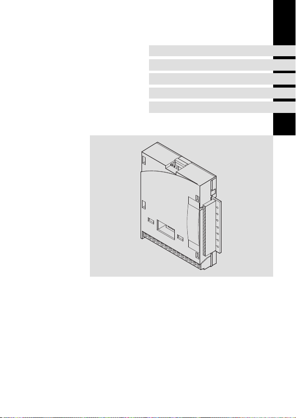
8200 motec 0.25 ... 0.37 kW
E82ZMFBC001
Bus-I/O
Bus-I/O
Bus E/S
Page 2

Lesen Sie zuerst diese Anleitung und die Dokumentation zum Grundgerät,
bevor Sie mit den Arbeiten beginnen!
Beachten Sie die enthaltenen Sicherheitshinweise.
Please read these instructions and the documentation of the standard
device before you start working!
Observe the safety instructions given therein!
Lire le présent fascicule et la documentation relative à l’appareil de base
avant toute manipulation de l’équipement !
Respecter les consignes de sécurité fournies.
Page 3
E82ZMFBC001
0
1
77
62
8 9 20 28
1122334
5
5
4
E1 E2 E3 E439A1
59
2
E82ZMFB009
Page 4

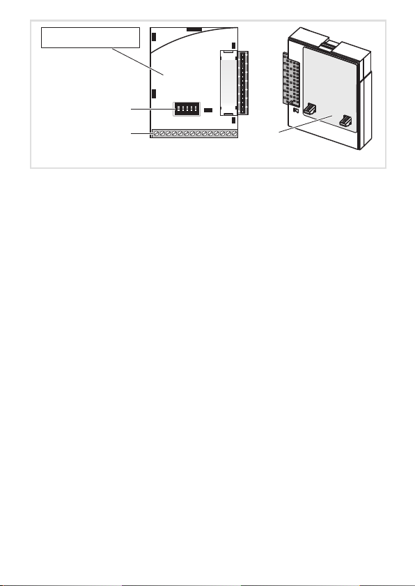
Legende zur Abbildung auf der Ausklappseite
Pos. Beschreibung Ausführliche
Funktionsmodul E82ZMFBC001
Schalter zur Konfigurierung des Analogeingangs (Klemme X3/8) 28
Digitale und analoge Ein- und Ausgänge, Steckerleiste X3 26
Typenschild 5
0Abb.0Tab. 0
Information
Tipp!
Informationen und Hilfsmittel rund um die Lenze-Produkte finden Sie im
Download-Bereich unter
http://www.Lenze.com
4
EDK82ZMFBC-001 DE/EN/FR 7.0
Page 5
Informationen zur Gültigkeit
APPLICATION
010 / 3A22
Diese Anleitung ist gültig für
ƒ Funktionsmodule Bus-I/O ab Version E82ZMFBC0013B
Diese Anleitung ist nur gültig zusammen mit der zugehörigen Dokumentation der für den
Einsatz zulässigen Grundgeräte.
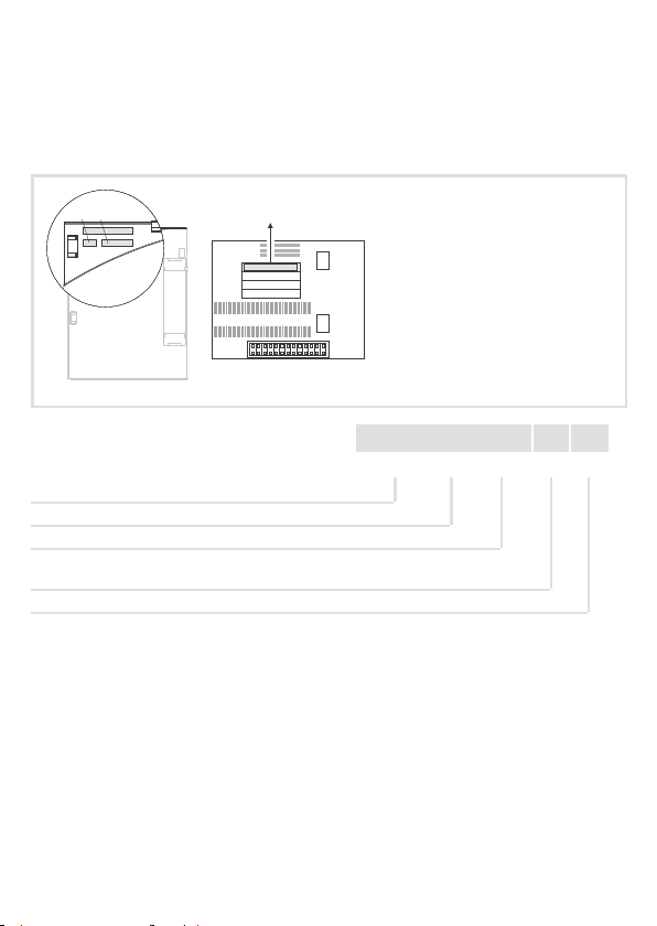
Identifikation
APPLICATION
010/ 3A22
Gerätereihe
Bus-I/O
Gerätegeneration
Variante
001: verlackte Ausführung
Hardwarestand
EDK82ZMFBC-001 DE/EN/FR 7.0
L
Type
Id.-No.
Prod.-No.
Ser.-No.
E82AF000P0B201XX
E82ZAFX005
c d e
E82ZMF B C 001 3B
5
Page 6

Bestellbezeichnung
E82ZMFBC0013B
Funktion
Das Funktionsmodul ermöglicht das Ansteuern von Lenze-Frequenzumrichtern
8200 motec mit analogen und digitalen Steuersignalen und die Kopplung an ein serielles
Kommunikationssystem.
Einsetzbarkeit
Das Funktionsmodul E82ZMFBC001 ist einsetzbar mit folgendem Grundgerät und
folgenden Feldbus-Funktionsmodulen:
Typ Bezeichnung ab Version
Frequenzumrichter 8200 motec E82MV251_2B, E82MV371_2B Vx14
Feldbus-Funktionsmodul
1)
Die digitalen Eingänge auf dem Feldbus-Funktionsmodul können nicht benutzt werden.
CANopen E82ZAFUC001 3B05
DeviceNet E82ZAFVC001 3B05
INTERBUS E82ZAFIC001 3A10
LECOM-B (RS485) E82ZAFLC001 3A10
PROFIBUS E82ZAFPC001 3A10
PROFIBUS-IO E82ZAFPC201
Systembus-CAN E82ZAFCC001 3A10
1)
VA05
6
EDK82ZMFBC-001 DE/EN/FR 7.0
Page 7

Inhalt i
1 Sicherheitshinweise 8................................................
Verwendete Hinweise 8...............................................
Allgemeine Sicherheitshinweise 10......................................
2 Technische Daten 11..................................................
Allgemeine Daten und Einsatzbedingungen 11...........................
Anschlussdaten 12....................................................
Abmessungen 13.....................................................
3Lieferumfang 14......................................................
4 Mechanische Installation 15............................................
Motormontage 15....................................................
Wandmontage 20....................................................
5 ElektrischeInstallation 23..............................................
EMV-gerechte Verdrahtung 23..........................................
Verdrahtung 24......................................................
6 Gerät zusammenbauen 27.............................................
7 Inbetriebnahme 28...................................................
Vor dem ersten Einschalten 28..........................................
Schalterstellung 28...................................................
Mit Lenze-Einstellung 29...............................................
EDK82ZMFBC-001 DE/EN/FR 7.0
7
Page 8

1 Sicherheitshinweise
Verwendete Hinweise
1 Sicherheitshinweise
Verwendete Hinweise
Um auf Gefahren und wichtige Informationenhinzuweisen, werden in dieser Dokumentation folgende Piktogramme und Signalwörter verwendet:
Sicherheitshinweise
Aufbau der Sicherheitshinweise:
Gefahr!
(kennzeichnet die Art und die Schwere der Gefahr)
Hinweistext
(beschreibt die Gefahr und gibt Hinweise, wie sie vermieden werden kann)
Piktogramm und Signalwort Bedeutung
Gefahr von Personenschäden durch gefährliche elektrische Spannung
Gefahr!
Gefahr!
Stop!
Hinweis auf eine unmittelbar drohende Gefahr, die den
Tod oder schwere Verletzungen zur Folge haben kann,
wenn nicht die entsprechenden Maßnahmen getroffen
werden.
Gefahr von Personenschäden durch eine allgemeine Gefahrenquelle
Hinweis auf eine unmittelbar drohende Gefahr, die den
Tod oder schwere Verletzungen zur Folge haben kann,
wenn nicht die entsprechenden Maßnahmen getroffen
werden.
Gefahr von Sachschäden
Hinweis auf eine mögliche Gefahr, die Sachschäden zur
Folge haben kann, wenn nicht die entsprechenden Maßnahmen getroffen werden.
8
EDK82ZMFBC-001 DE/EN/FR 7.0
Page 9

Anwendungshinweise
Piktogramm und Signalwort Bedeutung
Sicherheitshinweise
Verwendete Hinweise
1
Hinweis!
Tipp!
Wichtiger Hinweis für die störungsfreie Funktion
Nützlicher Tipp für die einfache Handhabung
Verweis auf andere Dokumentation
EDK82ZMFBC-001 DE/EN/FR 7.0
9
Page 10

1
Sicherheitshinweise
Allgemeine Sicherheitshinweise
Allgemeine Sicherheitshinweise
Gefahr!
Wenn Sie die folgenden grundlegenden Sicherheitsmaßnahmen missachten,
kann dies zu schweren Personenschäden und Sachschäden führen:
ƒ Lenze-Antriebskomponenten ...
... ausschließlich bestimmungsgemäß verwenden.
... niemals trotz erkennbarer Schäden in Betrieb nehmen.
... niemals technisch verändern.
... niemals unvollständig montiert in Betrieb nehmen.
... niemals ohne erforderliche Abdeckungen betreiben.
... können währendund nach dem Betrieb - ihrer Schutzart entsprechend - spannungsführende, auch bewegliche oder rotierende Teile haben. Oberflächen können heiß sein.
ƒ Alle Vorgaben der beiliegenden und zugehörigen Dokumentation beachten.
– Dies ist Voraussetzung für einen sicheren und störungsfreien Betrieb sowie für das
Erreichen der angegebenen Produkteigenschaften.
Die in diesem Dokument dargestellten verfahrenstechnischen Hinweise und Schaltungsausschnitte sind Vorschläge, deren Übertragbarkeit auf diejeweiligeAnwendung
überprüft werden muss. Für die Eignung der angegebenen Verfahren und Schaltungsvorschläge übernimmt der Hersteller keine Gewähr.
ƒ Alle Arbeiten mit und an Lenze-Antriebskomponenten darf nur qualifiziertes
Fachpersonal ausführen.
Nach IEC 60364 bzw. CENELEC HD 384 sind dies Personen, ...
... die mit Aufstellung, Montage, Inbetriebsetzung und Betrieb des Produkts vertraut
sind.
... die über die entsprechenden Qualifikationen für ihre Tätigkeit verfügen.
... die alle am Einsatzort geltenden Unfallverhütungsvorschriften, Richtlinien und Gesetze kennen und anwenden können.
Gefahr!
Beachten Sie die in den Anleitungen zum Grundgerät enthaltenen
Sicherheitshinweise und Restgefahren.
10
EDK82ZMFBC-001 DE/EN/FR 7.0
Page 11

Allgemeine Daten und Einsatzbedingungen
Technische Daten
2 TechnischeDaten
Allgemeine Daten und Einsatzbedingungen
Allgemeine Daten
Konformität und Approbation
Approbation
UL UL 508C Industrial Control Equipment
Personenschutz und Geräteschutz
Schutzart EN 60529 IP20
Einsatzbedingungen
Umgebungsbedingungen
Klimatisch
Lagerung IEC/EN 60721-3-1 1K3 (-25 ... +60 °C)
Transport IEC/EN 60721-3-2 2K3 (-25 ... +70 °C)
Betrieb Entsprechend der Daten des verwendeten Lenze Grundgerätes (siehe
Verschmutzung EN 61800-5-1 Verschmutzungsgrad 2
Dokumentation des Grundgerätes).
File No. E132659
für USA und Kanada
2
EDK82ZMFBC-001 DE/EN/FR 7.0
11
Page 12

2 Technische Daten
Anschlussdaten
Anschlussdaten
X3/ Werte
62 Auflösung: 10 Bit
Linearitätsfehler: ±0.5 %
Temperaturfehler: 0.3 % (0 … +60 °C)
Belastbarkeit I
8
Auflösung: 10 Bit
Linearitätsfehler: ±0.5 %
Temperaturfehler: 0.3 % (0 … +60 °C)
Eingangswiderstand
z R
Eingang
z R
9 Belastbarkeit I
7 potenzialgetrennt zu Klemme X3/39 (GND2)
20
28
E1
E2
E3
E4
39 potenzialgetrennt zu Klemme X3/7 (GND1)
A1 Belastbarkeit:
1)
Eingang
Belastbarkeit: Σ I
Eingangswiderstand: 3.3 kΩ
1)
1)
1 = HIGH (+12 … +30 V), SPS-Pegel, HTL
0 = LOW (0 … +3 V), SPS-Pegel, HTL
I
= 10 mA, bei interner Versorgung
max
I
= 50 mA, bei externer Versorgung
max
Wahlweise Frequenzeingang 0 … 10 kHz einspurig oder 0 ... 1 kHz zweispurig, Konfig. über C0425
=2mA
max
>50kΩ (bei Spannungssignal)
= 250 Ω (bei Stromsignal)
=10mA
max
=40mA
max
12
EDK82ZMFBC-001 DE/EN/FR 7.0
Page 13
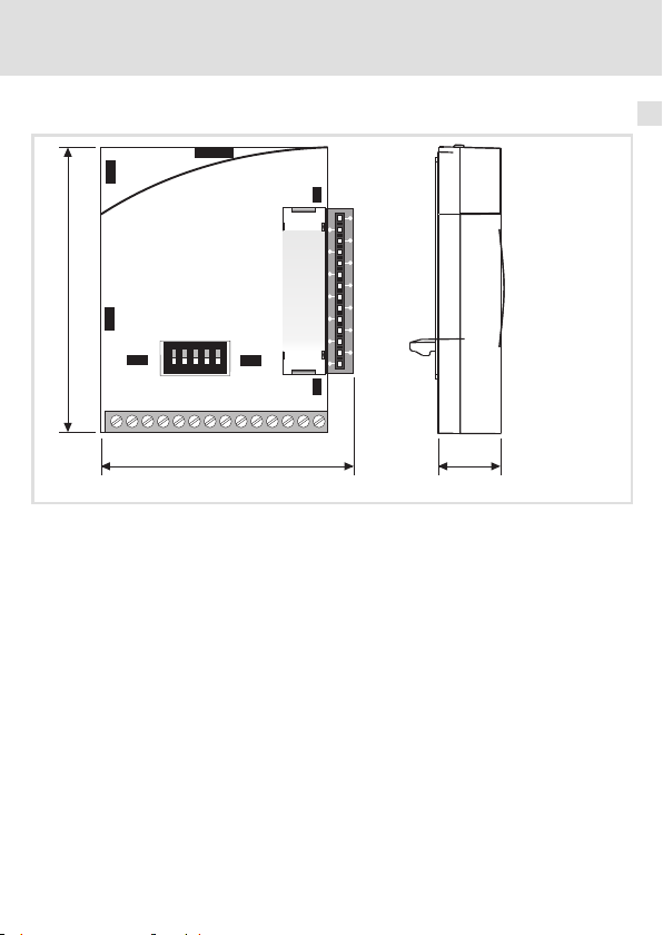
Abmessungen
64
62
1122334
4
77
8 9 20 28
alle Maße in mm
Technische Daten
5
5
E1 E2 E3 E439A1
59
57 15
Abmessungen
2
E82ZAFB009
EDK82ZMFBC-001 DE/EN/FR 7.0
13
Page 14
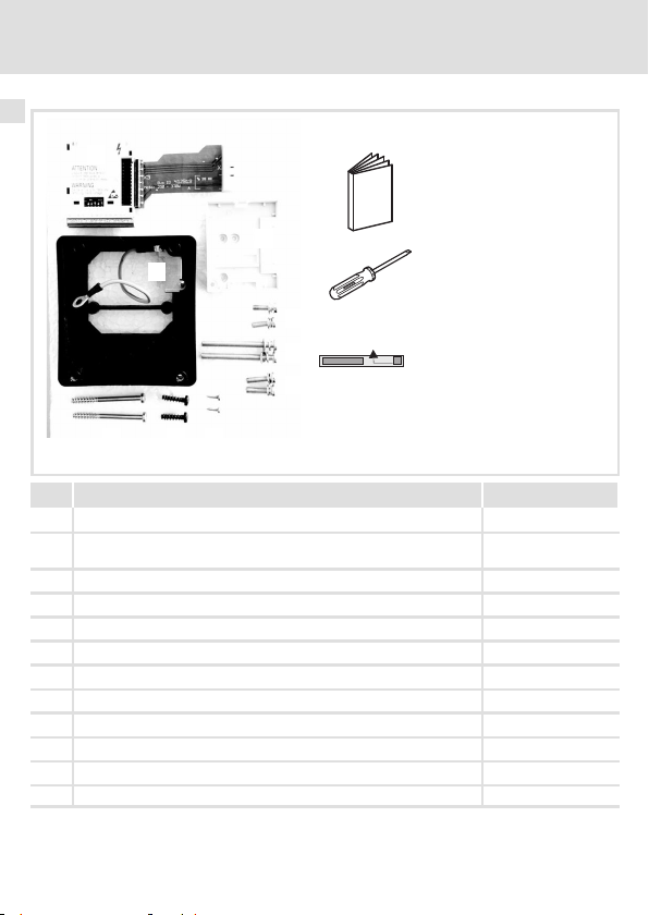
3Lieferumfang
3Lieferumfang
0
1
2
3
4
5
9
:
;
678
Pos Lieferumfang siehe
Bus-I/O Funktionsmodul mit Flachkabel
Gehäusewanne für Feldbus-Funktionsmodul, Schirmblech und PE-
Verbindung vormontiert
Befestigungsrahmen für Feldbus-Funktionsmodul 16, 21
2 Schrauben M5 x 16 für Motormontage
2 Schrauben M5 x 55 für Motormontage
2 Schrauben M5 x 20
2 Selbstformschrauben 3 x 10
2 Selbstformschrauben 5 x 18 für Wandmontage 21
2 Selbstformschrauben 5 x 55 für Wandmontage
Montageanleitung
Schraubendreher
Aufkleber
14
16
EDK82ZMFBC-001 DE/EN/FR 7.0
E82ZMFB008
Page 15

4 MechanischeInstallation
Stop!
Mechanische Belastung beschädigt das Flachkabel am
Bus-I/O-Funktionsmodul!
Deshalb das Flachkabel
ƒ nicht knicken,
ƒ nicht verdrehen,
ƒ nicht stark biegen.
Nicht am Flachkabel ziehen!
Motormontage
Vorbereitende Arbeiten
Mechanische Installation
Motormontage
4
1. Motor-Klemmenkasten demontieren.
2. Motor-Klemmenbrett demontieren.
3. Die Motor-Anschlüsse müssen ca. 15 cm lang sein, ggf. verlängern.
EDK82ZMFBC-001 DE/EN/FR 7.0
8200mot139
15
Page 16
4 Mechanische Installation
Motormontage
Montage
1
1
0
E82ZMFB002
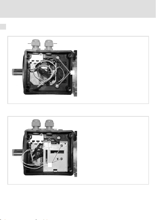
1. Gehäusewanne mit 2 Schrauben M5 × 16 auf den Motor schrauben.
2. Kabelverschraubungen M16 mit 10 mm Gewindelänge montieren .
0
E82ZMFB003
3. Befestigungsrahmen für Feldbus-Funktionsmodul mit 2 Selbstformschrauben 3 × 10
in die Gehäusewanne schrauben.
16
EDK82ZMFBC-001 DE/EN/FR 7.0
Page 17
Mechanische Installation
Motormontage
0
E82ZMFB004
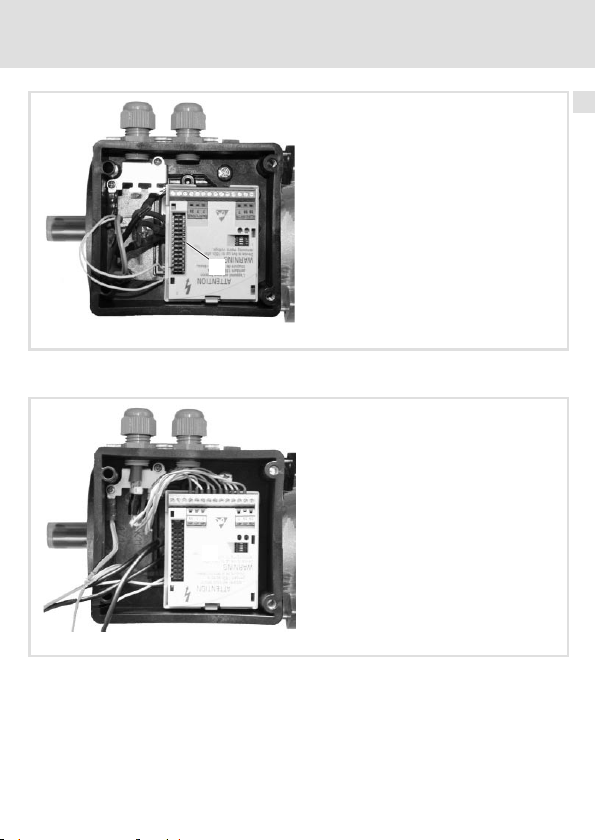
4. Feldbus-Funktionsmodul in den Befestigungsrahmen drücken, bis es einrastet.
5. Abdeckung der Steckerleiste entfernen .
0
4
6. Feldbus-Funktionsmodul verdrahten.
– Ummantelung des Buskabels ca. 10 cm entfernen.
– Schirm mit Kabelbinder auf Schirmblech auflegen.
– Feldbus-Funktionsmodul verdrahten (siehe dazugehörige Montageanleitung).
Klemme 28 (Reglersperre) des Feldbus-Funktionsmoduls ist inaktiv. Reglersperre
wird geschaltet über Klemme 28 des Bus-I/O-Funktionsmoduls.
EDK82ZMFBC-001 DE/EN/FR 7.0
E82ZMFB005
17
Page 18
4
Mechanische Installation
Motormontage
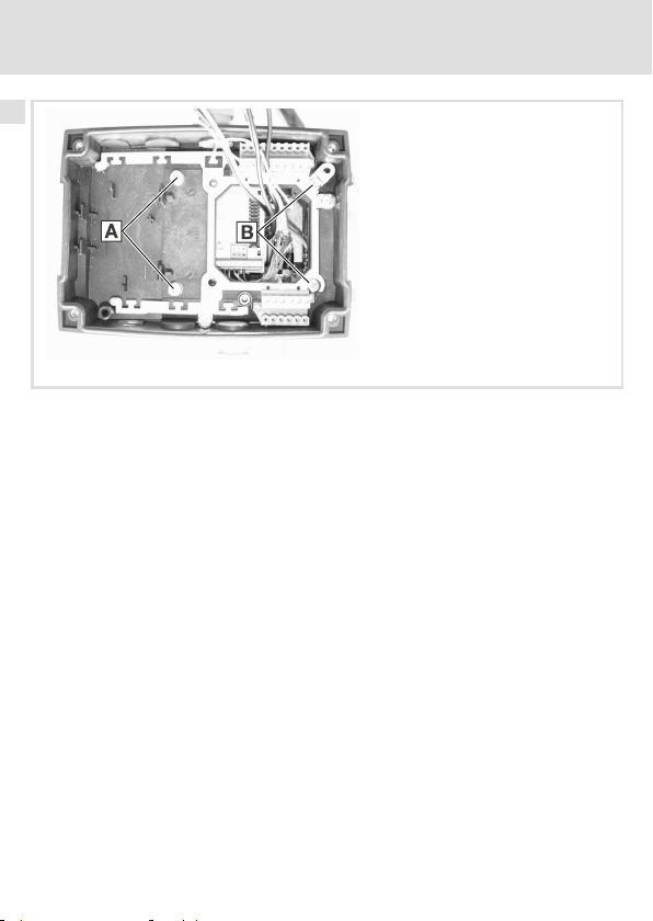
7. motec-Trägergehäuse montieren.
– Löcher an den Sollbruchstellen ausbrechen.
– 2SchraubenM5×20durchLöcher und2SchraubenM5×55durchLöcher
stecken.
– motec-Trägergehäuse auf der Gehäusewanne festschrauben.
E82ZMFB006
18
EDK82ZMFBC-001 DE/EN/FR 7.0
Page 19

0
Mechanische Installation
Motormontage
4
1
2
3
E82ZMFB007
8. Bus-I/O-Funktionsmodul in die Aufnahme im motec-Trägergehäuse drücken, bis es
einrastet.
9. Bus-I/O-Funktionsmodul verdrahten.
– Zweireihige Stiftleiste des Flachkabels in die zweireihige Buchse am
Feldbus-Funktionsmodul stecken .
– Klemmen des Bus-I/O-Funktionsmoduls verdrahten (Klemmenbelegung 26).
10. Netz und Motor anschließen (siehe Montageanleitung 8200 motec).
– Schutzleiter der Netzleitung unter PE-Anschluss klemmen.
– Schutzleiter der Motorleitung unter PE-Anschluss klemmen.
EDK82ZMFBC-001 DE/EN/FR 7.0
19
Page 20
4
Mechanische Installation
Wandmontage
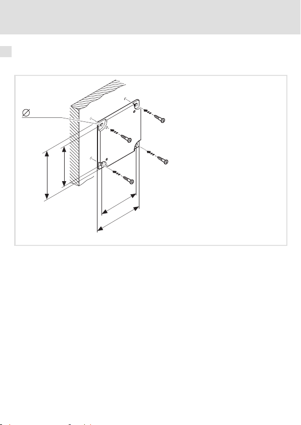
Wandmontage
Vorbereitende Arbeiten
5.3 mm
96
110
71
85
1. Wandplatte (Lieferumfang des motec) an die Wand schrauben.
82zmbrb_01
20
EDK82ZMFBC-001 DE/EN/FR 7.0
Page 21
Mechanische Installation
Wandmontage
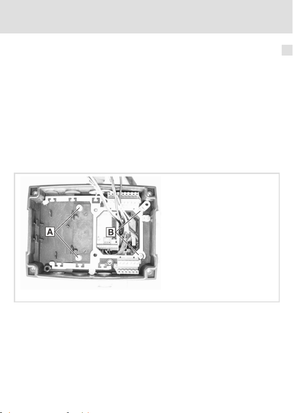
Montage
1. Gehäusewanne mit 2 Selbstformschrauben 5 × 18 auf die Wandplatte schrauben.
2. Kabelverschraubungen M16 mit 10 mm Gewindelänge montieren.
3. Befestigungsrahmen für Feldbus-Funktionsmodul mit 2 Selbstformschrauben 3 × 10
in die Gehäusewanne schrauben.
4. Feldbus-Funktionsmodul in den Befestigungsrahmen drücken, bis es einrastet.
5. Abdeckung der Steckerleiste entfernen.
6. Feldbus-Funktionsmodul verdrahten.
– Ummantelung des Buskabels ca. 10 cm entfernen.
– Schirm mit Kabelbinder auf Schirmblech auflegen.
– Feldbus-Funktionsmodul verdrahten (siehe dazugehörige Montageanleitung).
Klemme 28 (Reglersperre) des Feldbus-Funktionsmoduls ist inaktiv. Reglersperre
wird geschaltet über Klemme 28 des Bus-I/O-Funktionsmoduls.
E82ZMFB006
7. motec-Trägergehäuse montieren
– Löcher an den Sollbruchstellen ausbrechen.
– 2SchraubenM5×20durchLöcher und2Selbstformschrauben5×55durch
Löcher stecken.
– motec-Trägergehäuse auf der Gehäusewanne festschrauben.
4
EDK82ZMFBC-001 DE/EN/FR 7.0
21
Page 22
4
Mechanische Installation
Wandmontage
0
1
2
3
E82ZMFB007
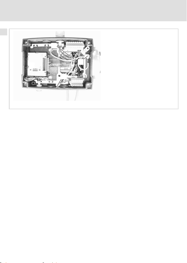
8. Bus-I/O-Funktionsmodul in die Aufnahme im motec-Trägergehäuse drücken, bis es
einrastet.
9. Bus-I/O-Funktionsmodul verdrahten.
– Zweireihige Stiftleiste des Flachkabels in die zweireihige Buchse am
Feldbus-Funktionsmodul stecken .
– Klemmen des Bus-I/O-Funktionsmoduls verdrahten (Klemmenbelegung 26).
10. Netz und Motor anschließen (siehe Montageanleitung 8200 motec).
– Schutzleiter der Netzleitung unter PE-Anschluss klemmen.
– Schutzleiter der Motorleitung unter PE-Anschluss klemmen.
22
EDK82ZMFBC-001 DE/EN/FR 7.0
Page 23
Elektrische Installation
EMV-gerechte Verdrahtung
5 ElektrischeInstallation
EMV-gerechte Verdrahtung
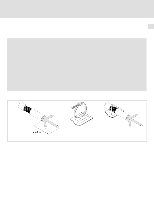
Für eine EMV-gerechte Verdrahtung beachten Sie folgende Punkte:
Hinweis!
ƒ Steuerleitungen getrennt von Motorleitungen verlegen.
ƒ Schirme so weit wie möglich an die Klemmen führen (ungeschirmte
Aderlänge < 40 mm).
ƒ Legen Sie die Schirme der Steuerleitungen bzw. Datenleitungen wie folgt
auf:
– Einseitig am Umrichter bei Leitungen mit analogen Signalen.
– Beidseitig bei Leitungen mit digitalen Signalen.
ƒ Beachten Sie die weiteren Hinweise zur EMV-gerechten Verdrahtung in der
Dokumentation des Grundgerätes.
Schirm auflegen
cde
8200mot045/046/047
1. Leitung vorbereiten.
2. Kabelbinder ins Schirmblech einlegen.
3. Leitung einlegen und Kabelbinder anziehen. Die Abschirmung muss fest mit dem
Schirmblech verbunden sein.
5
EDK82ZMFBC-001 DE/EN/FR 7.0
23
Page 24
5 Elektrische Installation
Verdrahtung
Verdrahtung
Daten der Anschlussklemmen
Bereich Werte
Elektrischer Anschluss Klemmenleiste mit Schraubanschluss
Anschlussmöglichkeiten
Anzugsmoment 0.22 ... 0.25 Nm (1.9 ... 2.2 lb-in)
Abisolierlänge 5mm
starr:
flexibel:
1.5 mm2(AWG 16)
ohne Aderendhülse
1.0 mm2(AWG 18)
mit Aderendhülse, ohne Kunststoffhülse
0.5 mm2(AWG 20)
mit Aderendhülse, mit Kunststoffhülse
0.5 mm2(AWG 20)
24
EDK82ZMFBC-001 DE/EN/FR 7.0
Page 25
Elektrische Installation
Versorgung über die interne Spannungsquelle (X3/20):
ƒ X3/28, Reglersperre (CINH)
ƒ X3/E1 .... X3/E4, digitale Eingänge
GND2
Verdrahtung
5
X3
GND1
62 8
AOUT1
GND1
+5V
9
897
0 … +5 V
+20V
20 28
1k … 10k
77
AIN1
E1 E2E3E439A1
DIGOUT1
59
Versorgung über eine externe Spannungsquelle:
ƒ X3/28, Reglersperre (CINH)
ƒ X3/E1 ... X3/E4, digitale Eingänge
Bus-I/O-Funktionsmodul Feldbus-Funktionsmodul
GND1
GND1
+20V
+5V
6278 9 20 28E1E2 E3 E4 39 A1 59
X3
AOUT1
7
AIN1
8
9
0 … +5 V
7
1k … 10k
Für den Betrieb notwendige Mindestverdrahtung
GND2
DIGOUT1
_
+
24 V ext.
(+12 V DC - 0 %
...
+30 V DC + 0 %,
max. 120 mA)
E82ZxFB005 E82ZxFB005a
...
GND1
7
39 28 59 720
24 V ext.
E82ZxFB004
GND1
+
_
EDK82ZMFBC-001 DE/EN/FR 7.0
25
Page 26

5
Elektrische Installation
Verdrahtung
X3/ Signaltyp Funktion
62 Analoger
Ausgang
7 - GND1, Bezugspotenzial für analoge Signale 8 Analoger
Eingang
9 - Interne, stabilisierte DC-Spannungsquelle für
20 - Interne DC-Spannungsquelle zum Ansteuern der
28
3)
E1
3)
E2
Digitale
Eingänge
E3 Gleichstrombremse (DCB) 1=DCB
E4 Drehrichtungsumkehr
39 - GND2, Bezugspotenzial für digitale Signale -
A1 Digitaler
Ausgang
59 - DC-Versorgung für X3/A1
1)
Ausgangspegel 0 … +10 V: Offset (C0109/C0422) und Verstärkung (C0108/C0420) anpassen
2)
Offset (C0026) und Verstärkung (C0027) für jedes Funktionsmodul separat abgleichen ...
- nach Austausch des Funktionsmoduls oder des Grundgerätes.
- nach Laden der Lenze-Einstellung.
3)
Wahlweise Frequenzeingang 0 … 10 kHz einspurig oder 0 ... 1 kHz zweispurig, Konfig. über C0425
(Lenze-Einstellung: Fettdruck)
Ausgangsfrequenz 0 … +6 V
Eingang für Istwert oder Sollwert
Bereich umschalten mit DIP-Schalter und in C0034:
z Spannungssignal
z Stromsignal
Sollwertpotenziometer
digitalen Eingänge und Ausgänge
Reglersperre (CINH) 1=Freigabe
Aktivierung von Festfrequenzen (JOG)
JOG1=20Hz
JOG2=30Hz
JOG3=40Hz
Rechts-/Linkslauf (CW/CCW)
Betriebsbereit
z interne Versorgung:
z externe Versorgung:
z intern (Brücke zu X3/20):
z extern:
Pegel
(Lenze-Einstellung: Fettdruck)
1)
0 … +10 V
0 … +5 V
0 … +10 V
-10 … +10 V
0 … +20 mA
+4 … +20 mA
+4 … +20 mA (drahtbruchüberwacht)
+5.2 V
+20 V ±10 % (Bezug: X3/7)
JOG1 1 0
JOG2 0 1
JOG3 1 1
CW 0
CCW 1
0 … +20 V
0 … +24 V
+20 V
+24 V
2)
E1 E2
E4
26
EDK82ZMFBC-001 DE/EN/FR 7.0
Page 27

Gerät zusammenbauen 6
6 Gerätzusammenbauen
Stop!
ƒ Um den motec und das Bus-I/O-Funktionsmodul nicht zu beschädigen,
unbedingt vor dem Zusammenbau
– die Schutzkappe des Bus-I/O-Funktionsmoduls entfernen und
aufbewahren.
– die FIF-Abdeckkappe entfernen und aufbewahren.
ƒ Vor Inbetriebnahme mit dem Aufkleber , der dem Funktionsmodul
beiliegt, das motec-Typenschild vervollständigen.
2.4 Nm
21 lb-in
S
0
2
Standard-I/O
1
IP65
AIF
8200mot059
EDK82ZMFBC-001 DE/EN/FR 7.0
27
Page 28

7 Inbetriebnahme
Vor dem ersten Einschalten
7 Inbetriebnahme
Vor dem er sten Einschalten
Die Inbetriebnahme ist abhängig von der Kombination der verwendeten Geräte (Bus-I/Ound Feldbus-Funktionsmodul). Die Vorgehensweisebei der Inbetriebnahmeistin den Dokumentationen zum Feldbus-System und zum Frequenzumrichter beschrieben.
Schalterstellung
ON
1ON234
5
OFF
Hinweis!
ƒ D ie DIP-Schalter und C0034 unbedingt auf den g leichen B ereich einstellen,
da sonst das analoge Eingangssignal an X3/8 durch das Grundgerät falsch
interpretiert wird.
ƒ Wird ein S oll wertpotentiometer intern über X3/9 versorgt, unbedingt die
DIP-Schalter auf den Spannungsbereich 0 ... 5 V einstellen. Andernfalls
kann nicht der ganze Drehzahlbereich durchfahrenwerden.
Signal an X3/8
1 2 3 4 5
0 ... 5 V OFF OFF ON OFF OFF 0
0 ... 10 V (L enze-Einstellung) OFF OFF ON OFF ON 0
0 ... 20 mA OFF OFF ON ON OFF 0
4 ... 20 mA OFF OFF ON ON OFF 1
4 ... 20 mA (drahtbruchüberwacht) OFF OFF ON ON OFF 3
-10 ... +10 V ON ON OFF OFF OFF 2
28
Schalterstellung
EDK82ZMFBC-001 DE/EN/FR 7.0
C0034
Page 29

Inbetriebnahme
Mit Lenze-Einstellung
Mit Lenze-Einstellung
Hinweis!
Das Grundgerät ist nur funktionsfähig, wenn ein HIGH-Pegel an X3/28 anliegt
(Reglerfreigabeüber Klemme).
ƒ Beachten Sie, dass die Reglersperre über mehrere Quellen gesetzt werden
kann. Die Quellen wirken wie eine Reihenschaltung von Schaltern.
ƒ Wenn der Antrieb trotz Reglerfreigabeüber X3/28 nicht anläuft,
überprüfenSie, ob noch über eine andere Quelle die Reglersperre gesetzt
ist. Eine andere Quelle könnte die -Taste des Keypad sein.
7
EDK82ZMFBC-001 DE/EN/FR 7.0
29
Page 30

Legend for fold-out page
Pos. Description Detailed
Function module E82ZMFBC001
Switch for the configuration of the analog input (terminal X3/8) 54
Digital and analog inputs and outputs, plug connector X3 52
Nameplate 31
0Fig.0Tab. 0
information
Tip!
Information and auxiliary devices around the Lenze products can be found in
the download area at
http://www.Lenze.com
30
EDK82ZMFBC-001 DE/EN/FR 7.0
Page 31

Validity information
APPLICATION
010 / 3A22
These instructions are valid for
ƒ Bus-I/O function modules as of version E82ZMFBC0013B
These instructions are only valid together with the documentation for the standard devices
permitted for the application.
Identification
APPLICATION
010/ 3A22
Series
Bus-I/O
Generation
Variant
001: coated design
Hardware version
EDK82ZMFBC-001 DE/EN/FR 7.0
L
Type
Id.-No.
Prod.-No.
Ser.-No.
E82AF000P0B201XX
E82ZAFX005
c d e
E82ZMF B C 001 3B
31
Page 32

Order designation
E82ZMFBC0013B
Function
The function module enables the 8200 motec frequency inverters from Lenze to be
controlled through analog and digital control signals and to be connected to a serial
communication system.
Application range
The function module E82ZMFBC001 can be used in conjunction with the following basic
device and the following fieldbus function modules:
Type Designation as of version
Frequency inverter 8200 motec E82MV2512B, E82MV3712B Vx14
Fieldbus function
module
1)
The digital inputs of the fieldbus function module cannot be used.
CANopen E82ZAFUC001 3B05
DeviceNet E82ZAFVC001 3B05
INTERBUS E82ZAFIC001 3A10
LECOM-B (RS485) E82ZAFLC001 3A10
PROFIBUS E82ZAFPC001 3A10
PROFIBUS-IO E82ZAFPC201
System bus-CAN E82ZAFCC001 3A10
1)
VA05
32
EDK82ZMFBC-001 DE/EN/FR 7.0
Page 33

Contents i
1 Safety instructions 34.................................................
Notes used 34........................................................
General safety instructions 36..........................................
2 Technical data 37.....................................................
General data and operating conditions 37...............................
Connection data 38...................................................
Dimensions 39.......................................................
3 Scope of supply 40....................................................
4 Mechanical installation 41.............................................
Motor mounting 41...................................................
Wall mounting 46....................................................
5 Electrical installation 49...............................................
Wiring according to EMC 49............................................
Wiring 50...........................................................
6 Device assembly 53...................................................
7 Commissioning 54....................................................
Before switching on 54................................................
Switch position 54....................................................
Commissioning using Lenze settings 55...................................
EDK82ZMFBC-001 DE/EN/FR 7.0
33
Page 34

1 Safety instructions
Notes used
1 Safetyinstructions
Notes used
The following pictographs and signal words are used in this documentation to indicate
dangers and important information:
Safety instructions
Structure of safety instructions:
Danger!
(characterises the type and severity of danger)
Note
(describes the danger and gives information about how to prevent dangerous
situations)
Pictograph and signal word Meaning
Danger of personal injury through dangerous electrical
voltage.
Danger!
Danger!
Stop!
Reference to an imminent danger that may result in
death or serious personal injury if the corresponding
measures are not taken.
Danger of personal injury through a general source of
danger.
Reference to an imminent danger that may result in
death or serious personal injury if the corresponding
measures are not taken.
Danger of property damage.
Reference to a possible danger that may result in
property damage if the corresponding measures are not
taken.
34
EDK82ZMFBC-001 DE/EN/FR 7.0
Page 35

Application notes
Pictograph and signal word Meaning
Safety instructions
Notes used
1
Note!
Tip!
Important note to ensure troublefree operation
Useful tip for simple handling
Reference to another documentation
EDK82ZMFBC-001 DE/EN/FR 7.0
35
Page 36

1
Safety instructions
General safety instructions
General safety instructions
Danger!
Disregarding the following basic safety measures may lead to severe personal
injury and damage to material assets!
ƒ Lenze drive components ...
... must only be used as directed.
... must never be commissioned in the event of visible damage.
... must never be technically changed.
... must never be commissioned before assembly has been completed.
... must never be operated without required covers.
... can includeliveandrotatingparts-dependingontheirtypeofprotection- during and
after operation. Surfaces can be hot.
ƒ All specifications of the corresponding enclosed documentation must be observed.
This is vital for a safe and trouble-free operation as well as for achieving the specified
product features.
The procedural notes and circuit details provided in this document are proposals which
theusermustcheckforsuitabilityfor his application. The manufacturer does notaccept
any liability for the suitability of the specified procedures and circuit proposals.
ƒ Only qualified, skilled personnel is permitted to work on and with Lenze drive
components.
According to IEC 60364 / CENELEC HD 384, these are persons who ...
... are familiar with the installation, mounting, commissioning, and operation of the
product.
... have the qualifications required for their occupation.
... know and are able to apply all national regulations for the preventions of accidents,
directives and laws applicable on site.
Danger!
Observe the safety instructions and residual hazards included in the
instructions for the standard device.
36
EDK82ZMFBC-001 DE/EN/FR 7.0
Page 37

General data and operating conditions
Technical data
2 Technicaldata
General data and operating conditions
General data
Conformity and approval
Approbation
UL UL 508C Industrial Control Equipment
Protection of persons and equipment
Type of protection EN 60529 IP20
Operating conditions
Ambient conditions
Climate
Storage IEC/EN 60721-3-1 1K3 (-25 to +60 °C)
Transport IEC/EN 60721-3-2 2K3 (-25 to +70 °C)
Operation Corresponding to the data of the Lenze standard device used (see
Pollution EN 61800-5-1 Degree of pollution 2
documentation of the standard device).
File No. E132659
for USA and Canada
2
EDK82ZMFBC-001 DE/EN/FR 7.0
37
Page 38

2 Technical data
Connection data
Connection data
X3/ Values
62 Resolution: 10 bit
Linearity distortion: ±0.5 %
Temperature distortion: 0.3 % (0 … +60 °C)
Carrying capacity I
8
Resolution: 10 bit
Linearity distortion: ±0.5 %
Temperature distortion: 0.3 % (0 … +60 °C)
Input resistance
z R
>50kΩ (with voltage signal)
Input
z R
= 250 Ω (with current signal)
9 Carrying capacity I
7 isolated from terminal X3/39 (GND2)
20
28
E1
E2
E3
E4
39 isolated from terminal X3/7 (GND1)
A1 Load capacity:
1)
Input
Load capacity: Σ I
Input resistance: 3.3 kΩ
1)
1)
1 = HIGH (+12 … +30 V), PLC level, HTL
0=LOW(0…+3V),PLClevel,HTL
I
= 10 mA, with internal supply
max
I
= 50 mA, with external supply
max
Frequency input alternatively 0 … 10 kHz single-track or 0 ... 1 kHz two-track, config. via C0425
max
max
max
=2mA
=10mA
=40mA
38
EDK82ZMFBC-001 DE/EN/FR 7.0
Page 39

Dimensions
64
1122334
77
62
8 9 20 28
All dimensions in mm
5
5
4
E1 E2 E3 E439A1
59
57 15
Technical data
Dimensions
E82ZAFB009
2
EDK82ZMFBC-001 DE/EN/FR 7.0
39
Page 40

3 Scope of supply
3 Scopeof supply
0
1
2
3
4
5
9
:
;
678
Pos. Scope of supply see
Bus-I/O function module with flat flexible cable
Housing shell for fieldbus function module, shield sheet and PE
connection preassembled
Fixing frame for fieldbus function module 42, 47
2 screws M5 x 16 for motor mounting
2 screws M5 x 55 for motor mounting
2 screws M5 x 20
2 self-tapping screws 3 x 10
2 self-tapping screws 5 x 18 for wall mounting 47
2 self-tapping screws 5 x 55 for wall mounting
Mounting Instructions
Screw driver
Sticker
40
EDK82ZMFBC-001 DE/EN/FR 7.0
E82ZMFB008
42
Page 41

Mechanical installation
4 Mechanicalinstallation
Stop!
Mechanical stress damages the flat flexible cable of the bus-I/O function
module!
The flat flexible cable must
ƒ not be kinked,
ƒ not be twisted,
ƒ notbebenttightly.
Do not pull at the flat flexible cable!
Motor mounting
Preliminary works
Motor mounting
4
8200mot139
1. Dismount motor terminal box.
2. Dismount motor terminal board.
3. The motor connections must be approx.15cmlong,ifnecessary,extendthem.
EDK82ZMFBC-001 DE/EN/FR 7.0
41
Page 42

4 Mechanical installation
Motor mounting
Mounting
1
1
0
E82ZMFB002
1. Screw the housing shell to the motor using 2 screws M5 × 16 .
2. Mount the cable glands M16 using a 10 mm thread length .
0
E82ZMFB003
3. Screw the fixing frame for the fieldbus function module into the housing shell using
2 self-tapping screws 3 × 10 .
42
EDK82ZMFBC-001 DE/EN/FR 7.0
Page 43

Mechanical installation
Motor mounting
0
E82ZMFB004
4. Press the fieldbus function module into the fixing frame until it snaps into place.
5. Remove the cover of the terminal strip .
0
4
6. Wire the fieldbus function module.
– Remove approx. 10 cm of the cable sheath.
– Connect the shield to the shield sheet using the cable tie.
– Wire the fieldbus function module (see corresponding Mounting Instructions).
Terminal 28(controllerinhibit)ofthefieldbusfunction module is inactive. Controller
is inhibited via terminal 28 of the bus-I/O function module.
EDK82ZMFBC-001 DE/EN/FR 7.0
E82ZMFB005
43
Page 44

4
Mechanical installation
Motor mounting
7. Mount motec carrier housing.
– Break out holes at the predetermined breaking points .
– Insert 2 screws M5 × 20 through holes and2screwsM5×55throughholes.
– Screw motec carrier housing onto the housing shell.
E82ZMFB006
44
EDK82ZMFBC-001 DE/EN/FR 7.0
Page 45

0
Mechanical installation
Motor mounting
4
1
2
3
E82ZMFB007
8. Insert the bus-I/O function module into the receptacle in the motec carrier housing
until it snaps into place.
9. Wire the bus-I/O function module.
– Plug the double-row pin strip of the flat flexible cable into the double-row socket
of the fieldbus function module .
– Wire the terminals of the bus-I/O function module , terminal assignment
10. Connect mains and motor (see Mounting Instructions for the 8200 motec).
– Connect PE conductor of mains cable to PE connection .
– Connect PE conductor of motor cable to PE connection .
52).
EDK82ZMFBC-001 DE/EN/FR 7.0
45
Page 46

4
Mechanical installation
Wall mounting
Wall mounting
Preliminary works
5.3 mm
96
110
71
85
1. Screw the mounting plate (supplied with the motec) to the wall.
82zmbrb_01
46
EDK82ZMFBC-001 DE/EN/FR 7.0
Page 47

Mechanical installation
Wall mounting
Mounting
1. Mount the housing shell to the mounting plate using the 2 self-tapping screws
5 × 18.
2. Mount the cable glands M16 using a 10 mm thread length.
3. Screw the fixing frame for the fieldbus function module into the housing shell using
2 self-tapping screws 3 × 10.
4. Press the fieldbus function module into the fixing frame until it snaps into place.
5. Remove the cover of the terminal strip.
6. Wire the fieldbus function module.
– Remove approx. 10 cm of the cable sheath.
– Connect the shield to the shield sheet using the cable tie.
– Wire the fieldbus function module (see corresponding Mounting Instructions).
Terminal 28(controllerinhibit)ofthefieldbusfunction module is inactive. Controller
is inhibited via terminal 28 of the bus-I/O function module.
4
7. Mount motec carrier housing
– Break out holes at the predetermined breaking points .
– Insert 2 screws M5 × 20 through holes and 2 self-tapping screws 5 × 55 through
holes .
– Screw motec carrier housing onto the housing shell.
EDK82ZMFBC-001 DE/EN/FR 7.0
E82ZMFB006
47
Page 48

4
Mechanical installation
Wall mounting
0
1
2
3
E82ZMFB007
8. Insert the bus-I/O function module into the receptacle in the motec carrier housing
until it snaps into place.
9. Wire the bus-I/O function module.
– Plug the double-row pin strip of the flat flexible cable into the double-row socket
of the fieldbus function module .
– Wire the terminals of the bus-I/O function module , terminal assignment
10. Connect mains and motor (see Mounting Instructions for the 8200 motec).
– Connect PE conductor of mains cable to PE connection .
– Connect PE conductor of motor cable to PE connection .
52).
48
EDK82ZMFBC-001 DE/EN/FR 7.0
Page 49

Electrical installation
Wiring according to EMC
5 Electricalinstallation
Wiring according to EMC
Please observe the following for wiring according to EMC guidelines:
Note!
ƒ Separate control cables from motor cables.
ƒ Lead the shields as far as possible to the terminals (unshielded core length
<40mm).
ƒ Connect control and data cable shields as follows:
– Analog signal cable shields must be connected with one end at the
inverter.
– Digital signal cable shields must be connected with both ends.
ƒ More information about wiring according to EMC guidelines can be
obtained from the corresponding documentation for the standard device.
How to connect the shield
cde
8200mot045/046/047
1. Prepare cable.
2. Insert cable tie into shield sheet.
3. Insert cable and tighten cable tie. Shield and shield sheet must be tightly connected.
5
EDK82ZMFBC-001 DE/EN/FR 7.0
49
Page 50

5 Electrical installation
Wiring
Wiring
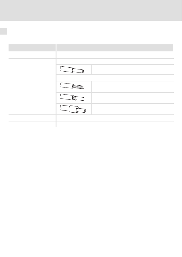
Terminal data
Range Values
Electrical connection Terminal strip with screw connection
Possible connections
Tightening torque 0.22 ... 0.25 Nm (1.9 ... 2.2 lb-in)
Bare end 5mm
rigid:
flexible:
1.5 mm2(AWG 16)
without wire end ferrule
1.0 mm2(AWG 18)
with wire end ferrule, without plastic sleeve
0.5 mm2(AWG 20)
with wire end ferrule, with plastic sleeve
0.5 mm2(AWG 20)
50
EDK82ZMFBC-001 DE/EN/FR 7.0
Page 51

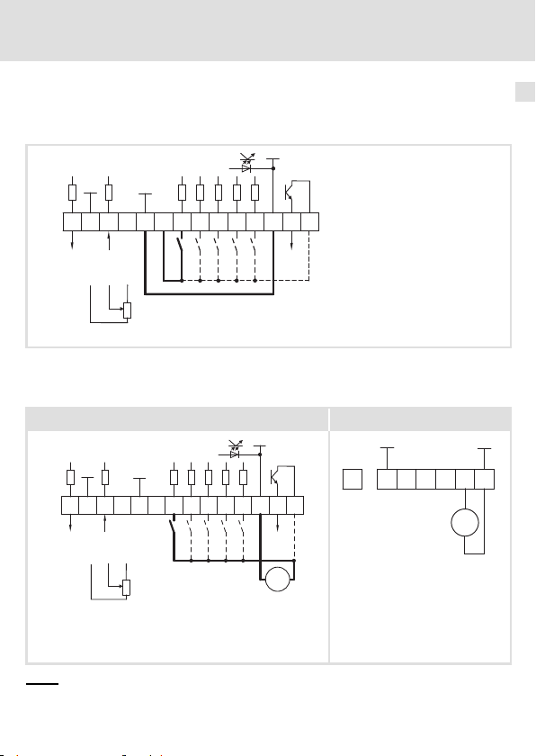
Supply via the internal voltage source (X3/20):
ƒ X3/28, controller inhibit (CINH)
ƒ X3/E1 .... X3/E4, digital inputs
GND2
Electrical installation
Wiring
5
X3
GND1
62 8
AOUT1
GND1
+5V
9
897
0 … +5 V
+20V
20 28
1k … 10k
77
AIN1
E1 E2E3E439A1
DIGOUT1
59
Supply via an external voltage source:
ƒ X3/28, controller inhibit (CINH)
ƒ X3/E1 ... X3/E4, digital inputs
Bus-I/O function module Fieldbus function module
GND1
GND1
+20V
+5V
6278 9 20 28E1E2 E3 E4 39 A1 59
X3
AOUT1
7
AIN1
8
9
0 … +5 V
7
1k … 10k
The min. wiring requirements for operation
GND2
DIGOUT1
_
+
24 V ext.
(+12 V DC - 0 %
...
+30 V DC + 0 %,
max. 120 mA)
E82ZxFB005 E82ZxFB005a
...
GND1
7
39 28 59 720
24 V ext.
E82ZxFB004
GND1
+
_
EDK82ZMFBC-001 DE/EN/FR 7.0
51
Page 52

5
Electrical installation
Wiring
X3/ Signal
type
62 Analog
output
7 - GND1, Reference potential for analog signals 8 Analog
input
9 - Internal, stabilised DC voltage source for the
20 - Internal DC voltage supply for control of digital
28
3)
E1
3)
E2
Digital
inputs
E3 DC-injection brake (DCB) 1=DCB
E4 Change of direction of rotation
39 - GND2, Referen ce potential for digital signals -
A1 Digital
output
59 - DC supply for X3/A1
1)
Output level 0 … +10 V: Adapt offset (C0109/C0422) and gain (C0108/C0420)
2)
Adjust offset (C0026) and gain (C0027) separately for each function module ...
- after replacing the function module or the basic device.
- after loading the Lenze setting.
3)
Frequency input alternatively 0 … 10 kHz single-track or 0 ... 1 kHz two-track, config. via C0425
Function
(Lenze setting: bold print)
Output frequency 0 … +6 V
Input for actual value or setpoint
Switch over the range with the DIP switch and in C0034:
z Voltage signal
z Current signal
setpoint potentiometer
inputs and outputs
Controller inhibit (CINH) 1=enable
Activation of JOG frequencies
JOG1=20Hz
JOG2=30Hz
JOG3=40Hz
CW/CCW rotation
Ready for operation
z internal supply:
z external supply:
z internal (bridge to X3/20):
z external:
Level
(Lenze setting: bold print)
0 … +10 V
0 … +5 V
0 … +10 V
-10 … +10 V
0 … +20 mA
+4 … +20 mA
+4 … +20 mA (open-circuit
monitored)
+5.2 V
+20 V ±10 % (ref.: X3/7)
JOG1 1 0
JOG2 0 1
JOG3 1 1
CW 0
CCW 1
0 … +20 V
0 … +24 V
+20 V
+24 V
1)
2)
e1 E2
E4
52
EDK82ZMFBC-001 DE/EN/FR 7.0
Page 53

Device assembly 6
6 Deviceassembly
Stop!
ƒ In order to avoid damages of the motec and the bus-I/O function module,
proceed as follows before starting to assemble:
– Remove and keep the protecting cap of the bus-I/O function module .
– Remove and keep the FIF cap .
ƒ Complete the motec nameplate with the sticker that is delivered
together with the function module.
2.4 Nm
21 lb-in
S
0
2
Standard-I/O
1
IP65
AIF
8200mot059
EDK82ZMFBC-001 DE/EN/FR 7.0
53
Page 54

7 Commissioning
Before switching on
7 Commissioning
Before switching on
Commissioning depends on the device combination (bus-I/O and fieldbus function
module). The commissioning procedure is described in the documentation on the fieldbus
systemand the frequency inverter.
Switch position
ON
1ON234
5
OFF
Note!
ƒ Make sure to set the DIP switch and C0034 to the same range, otherwise
the analog input signal at X3/8 will be interpreted incorrectly by the basic
device.
ƒ If a setpoint potentionmeter is supplied internally via X3/9, make sure to
set the DIP switch to the voltage range 0 ... 5 V. Otherwise it will be
impossibleto cover the entire speed range.
Signal at X3/8
1 2 3 4 5
0 ... 5V OFF OFF ON OFF OFF 0
0 ... 10 V (Lenze setting) OFF OFF ON OFF ON 0
0 ... 20 mA OFF OFF ON ON OFF 0
4 ... 20 mA OFF OFF ON ON OFF 1
4 ... 20 mA (open-circuit monitored) OFF OFF ON ON OFF 3
-10 ... +10 V ON ON OFF OFF OFF 2
54
Switch position
EDK82ZMFBC-001 DE/EN/FR 7.0
C0034
Page 55

Commissioning using Lenze settings
Commissioning using Lenze settings
Note!
The basic device is only functioning if a HIGH level is appliedto X3/28
(controller release via terminal).
ƒ Please observethat the controller can be inhibited through various
sources. All sources act like a series connection of switches.
ƒ If the drive does not start in spite of the controller release via X3/28, check
if the controller inhibit is set via another source. Another source could be
the key of the keypad.
Commissioning
7
EDK82ZMFBC-001 DE/EN/FR 7.0
55
Page 56

Légende de l’illustration de la page dépliante
Pos. Description Informations
Module de fonction E82ZMFBC001
Interrupteur pour la configuration de l’entrée analogique (borne X3/8) 80
Entrées et sorties numériques et analogiques, bornier enfichable X3 78
Plaque signalétique 57
0Fig.0Tab. 0
détaillées
Conseil !
Toutes les informations relatives aux produits Lenze peuvent être téléchargées
sur notre site à l’adresse suivante :
http://www.Lenze.com
56
EDK82ZMFBC-001 DE/EN/FR 7.0
Page 57

Informations relatives à la validité
APPLICATION
010 / 3A22
Le présent document s’applique au produit suivant :
ƒ modules de fonction bus E/S à partir de la version E82ZMFBC0013B.
Ce document est uniquement valable avec la documentation relative aux appareils de base
compatibles.
Identification
APPLICATION
010/ 3A22
Série d’appareils
Bus E/S
Génération d’appareils
Variante
001 : version vernie
Version matérielle
EDK82ZMFBC-001 DE/EN/FR 7.0
L
Type
Id.-No.
Prod.-No.
Ser.-No.
E82AF000P0B201XX
E82ZAFX005
c d e
E82ZMF B C 001 3B
57
Page 58

Référencedecommande
E82ZMFBC0013B
Fonction
Lemodulede fonction permet de relierlesconvertisseursdefréquence 8200 motecdeLenze
à un système de communication série et de les commander via signaux analogiques et
numériques.
Utilisation
Le module de fonction E82ZMFBC001 peut être utilisé sur les appareils de base et
conjointement avec les modules de fonction bus de terrain suivants :
Type Commande Apartirdelaversion
Convertisseurs de
fréquence
Modules de fonction
bus de terrain
1)
Les entrées numériques sur le module de fonction bus de terrain ne doivent pas être utilisées.
8200 motec E82MV2512B, E82MV3712B Vx14
CANopen E82ZAFUC001 3B05
DeviceNet E82ZAFVC001 3B05
INTERBUS E82ZAFIC001 3A10
LECOM-B (RS485) E82ZAFLC001 3A10
PROFIBUS E82ZAFPC001 3A10
PROFIBUS-IO E82ZAFPC201
Bus Système CAN E82ZAFCC001 3A10
1)
VA05
58
EDK82ZMFBC-001 DE/EN/FR 7.0
Page 59

Sommaire i
1 Consignes de sécurité 60...............................................
Consignesutilisées 60.................................................
Consignes générales 62................................................
2 Spécifications techniques 63...........................................
Caractéristiquesgénérales et conditions d’utilisation 63....................
Données de raccordement 64...........................................
Encombrements 65...................................................
3 Equipement livré 66...................................................
4 Installation mécanique 67..............................................
Montage sur le moteur 67..............................................
Fixation murale 72....................................................
5 Installation él ectrique 75...............................................
CâblageconformeCEM 75..............................................
Câblage 76..........................................................
6 Assemblagede l’appareil 79............................................
7Miseenservice 80....................................................
Avantlapremièremisesoustension 80...................................
Position de l’interrupteur 80............................................
Avec réglage Lenze 81.................................................
EDK82ZMFBC-001 DE/EN/FR 7.0
59
Page 60

1 Consignes de sécurité
Consignes utilisées
1 Consignesdesécurité
Consignes utilisées
Pour indiquer des risques et des informations importantes, la présente documentation
utilise les mots et symboles suivants :
Consignes de sécurité
Présentation des consignes de sécurité
Danger !
(Lepictogrammeindiqueletypederisque.)
Explication
(L’explication décrit le risque et les moyens de l’éviter.)
Pictogramme et mot associé Explication
Situation dangereuse pour les personnes en raison d’une
tension électrique élevée
Danger !
Danger !
Stop !
Indication d’un danger imminent qui peut avoir pour
conséquences des blessures mortelles ou très graves en
cas de non-respect des consignes de sécurité
correspondantes
Situation dangereuse pour les personnes en raison d’un
danger d’ordre général
Indication d’un danger imminent qui peut avoir pour
conséquences des blessures mortelles ou très graves en
cas de non-respect des consignes de sécurité
correspondantes
Risques de dégâts matériels
Indication d’un risque potentiel qui peut avoir pour
conséquences des dégâts matériels en cas de non-respect
des consignes de sécurité correspondantes
60
EDK82ZMFBC-001 DE/EN/FR 7.0
Page 61

Consignes d’utilisation
Pictogramme et mot associé Explication
Consignes de sécurité
Consignes utilisées
1
Remarque
importante !
Conseil !
Remarque importante pour assurer un fonctionnement
correct
Conseil utile pour faciliter la mise en oeuvre
Référence à une autre documentation
EDK82ZMFBC-001 DE/EN/FR 7.0
61
Page 62

1
Consignes de sécurité
Consignes générales
Consignes générales
Danger !
Le non-respect des consignes de sécuritédebasesuivantespourraitentraîner
de sévères blessures et de graves dommages matériels.
ƒ Les composants d’entraînement Lenze...
... doivent être utilisés uniquement conformément à la fonction.
... ne doivent jamais être mis en service si des dommages sont décelés.
... ne doivent jamais être modifiés d’un point de vue technique.
... ne doivent jamais être mis en service s’ils ne sont pas montés intégralement.
... ne doivent jamais être mis en service sans le capot obligatoire.
... peuvent - selon l’indice de protection - contenir des pièces sous tension, en
mouvement ou en rotation. Les surfaces peuvent être brûlantes.
ƒ Respecter toutes les consignes fournies dans la documentation associée.
– Il s’agit de la condition préalable pour garantir un fonctionnement sûr et correct et
pour obtenir les caractéristiques du produit indiquées.
Lesconsignesetlesinstructionsdecâblage fournies dans ce document sont des
recommandations. Leur validité pour l’application concernée doit être vérifiée. Le
constructeur n’assume aucune responsabilité pour ce qui est de l’adéquation des
systèmes et des recommandations de câblage décrits dans le présent manuel.
ƒ Les travaux réalisés avec et au niveau des composants d’entraînement Lenze ne
doivent être exécutés que par un personnel qualifié et habilité.
Selon la norme CEI 60364 ou CENELEC HD 384, ces personnes doivent ...
... connaître parfaitement l’installation, le montage, la mise en service et le
fonctionnement du produit.
... posséder les qualifications appropriées pour l’exercice de leur activité.
... connaître toutes les prescriptions pour la prévention d’accidents, directives et lois
applicables sur le lieu d’utilisation et être en mesure de les appliquer.
Danger !
Tenir compte des consignes de sécurité et des dangers résiduels décrits dans la
documentation de l’appareil de base concerné.
62
EDK82ZMFBC-001 DE/EN/FR 7.0
Page 63

Caractéristiques générales et conditions d’utilisation
Spécifications techniques
2 Spécificationstechniques
Caractéristiques générales et conditions d’utilisation
Caractéristiques générales
Conformité et homologation
Homologation
UL UL 508C Industrial Control Equipment
Protection des personnes et protection de l’appareil
Indice de protection EN 60529 IP20
Conditions d’utilisation
Conditions ambiantes
Conditions climatiques
Stockage CEI/EN 60721-3-1 1K3 (-25 ... +60 °C)
Transport CEI/EN 60721-3-2 2K3 (-25 ... +70 °C)
Fonctionnement Conformément aux données de l’appareil de base Lenze utilisé (voir la
Pollution ambiante
admissible
documentation de l’appareil de base).
EN 61800-5-1 Degré de pollution 2
Dossier N° E132659
pour les Etats-Unis et le Canada
2
EDK82ZMFBC-001 DE/EN/FR 7.0
63
Page 64

2 Spécifications techniques
Données de raccordement
Données de raccordement
X3/ Valeurs
62 Résolution : 10 bits
Erreur de linéarité : ±0.5 %
Erreur de température : 0,3 % (0 … +60 °C)
Charge admissible I
8
Résolution : 10 bits
Erreur de linéarité : ±0.5 %
Erreur de température : 0.3 % (0 … +60 °C)
Résistance d’entrée
z R
>50kΩ (signal de tension)
Entrée
z R
= 250 Ω (signal de courant)
9 Capacité de charge I
7 Avec séparation de potentiel sur la borne X3/39 (GND2)
20
28
E1
E2
E3
E4
39 Avec séparation de potentiel sur la borne X3/7 (GND1)
A1 Charge admissible :
1)
Entrée
Charge admissible : Σ I
Résistance d’entrée : 3.3 kΩ
1)
1)
1 = HAUT (+12 … +30 V), niveau de l’API, HTL
0 = BAS (0 … +3 V), niveau de l’API, HTL
I
= 10 mA, avec alimentation interne
max
I
= 50 mA, avec alimentation externe
max
Au choix : entrée de fréquence 0 … 10 kHz à une voie ou 0 ... 1 kHz à deux voies, configuration via
C0425
max
max
=2mA
=10mA
max
=40mA
64
EDK82ZMFBC-001 DE/EN/FR 7.0
Page 65

Encombrements
64
77
62
5
1122334
5
4
8 9 20 28
E1 E2 E3 E439A1
57 15
Toutes les cotes en mm
Spécifications techniques
Encombrements
59
2
E82ZAFB009
EDK82ZMFBC-001 DE/EN/FR 7.0
65
Page 66

3 Equipement livré
3 Equipementlivré
0
1
2
3
4
5
9
:
;
678
Pos Contenu de l’emballage voir
Module de fonction bus E/S avec câble en nappe
Enveloppe prémontée pour module de fonction bus de terrain, tôle de
blindage et raccord PE
Cadre de fixation pour module de fonction bus de terrain 68, 73
2 vis M5 x 16 pour montage sur le moteur
2 vis M5 x 55 pour montage sur le moteur
2 vis M5 x 20
2 vis autotaraudeuses 3 x 10
2 vis autotaraudeuses 5 x 18 pour fixation murale 73
2 vis autotaraudeuses 5 x 55 pour fixation murale
Instructions de montage
Tournevis
Autocollant
66
EDK82ZMFBC-001 DE/EN/FR 7.0
E82ZMFB008
68
Page 67

Installation mécanique
Montage sur le moteur
4 Installationmécaniqu e
Stop !
Toute contrainte mécanique entraîne un endommagement du câble en nappe
surlemoduledefonctionbusE/S!
Ne pas contraindre le câble en nappe à
ƒ des pliages,
ƒ des torsions et
ƒ desflexionsimportantes.
Ne pas tirer sur le câble en nappe !
Montage sur le moteur
Préparatifs
4
8200mot139
1. Démonter la boîte à bornes du moteur.
2. Démonter la planchette à bornes du moteur.
3. La longueur minimale des câbles moteur est env. 15 cm. Le cas échéant, les prolonger.
EDK82ZMFBC-001 DE/EN/FR 7.0
67
Page 68

4 Installation mécanique
Montage sur le moteur
Montage
1
1
0
E82ZMFB002
1. Visser l’enveloppe sur le moteur à l’aide de deux vis M5 x 16 .
2. Monter les raccords vissés de câbles M16 avec longueur filetée 10 mm .
0
E82ZMFB003
3. Visser le cadre de fixation pour le module de fonction bus de terrain sur l’enveloppe à
l’aide de deux vis autotaraudeuses 3 x 10 .
68
EDK82ZMFBC-001 DE/EN/FR 7.0
Page 69

Installation mécanique
Montage sur le moteur
0
4. Encliqueter le module de fonction bus de terrain dans le cadre de fixation.
5. Retirer la protection du bornier enfichable .
0
4
E82ZMFB004
E82ZMFB005
6. Câbler le module de fonction bus de terrain.
– Dénuder le câble bus d’env. 10 cm.
– Positionner le blindage avec serre-câble sur la tôle de blindage.
– Câbler le module de fonction bus de terrain (voir instructions de montage
afférentes).
La borne 28 (blocage variateur) du module de fonction bus de terrain n’est pas
activée.Leblocagevariateurestactivévialaborne28dumoduledefonctionbusE/S.
EDK82ZMFBC-001 DE/EN/FR 7.0
69
Page 70

4
Installation mécanique
Montage sur le moteur
7. Monter l’embase du motec.
– Percer les opercules aux endroits prévus .
– Insérer 2 vis M5 x 20 dans les orifices et 2 vis M5 x 55 dans les orifices .
– Visser l’embase motec sur l’enveloppe.
E82ZMFB006
70
EDK82ZMFBC-001 DE/EN/FR 7.0
Page 71

0
Installation mécanique
Montage sur le moteur
4
1
2
3
8. EncliqueterlemoduledefonctionbusE/S dans l’embase du motec.
9. Câbler le module de fonction bus E/S.
– Enficher le connecteur à deux rangs du câble en nappe dans la prise à deux rangs
surlemoduledefonctionbusdeterrain
– Câbler les bornes du module de fonction bus E/S (affectation des bornes
10. Connecter le réseau et le moteur (voir instructions de montage 8200 motec).
– Serrer le conducteur de protection du câble réseau sous le raccord PE .
– Serrer le conducteur de protection du câble moteur sous le raccord PE .
E82ZMFB007
78).
EDK82ZMFBC-001 DE/EN/FR 7.0
71
Page 72

4
Installation mécanique
Fixation murale
Fixation murale
Préparatifs
5.3 mm
96
110
71
85
1. Monter la plaque de montage (comprise dans l’équipement du motec) au mur.
82zmbrb_01
72
EDK82ZMFBC-001 DE/EN/FR 7.0
Page 73

Installation mécanique
Fixation murale
Montage
1. Visser l’enveloppe sur la plaque de montage à l’aide de deux vis autotaraudeuses
5 x 18.
2. Monter les raccords vissés de câbles M16 avec longueur filetée 10 mm.
3. BVisser le cadre de fixation pour le module de fonction bus de terrain sur l’enveloppe
à l’aide de deux vis autotaraudeuses 3 x 10.
4. Encliqueter le module de fonction bus de terrain dans le cadre de fixation.
5. Retirer la protection du bornier enfichable.
6. Câbler le module de fonction bus de terrain.
– Dénuder le câble bus d’env. 10 cm.
– Positionner le blindage avec serre-câble sur la tôle de blindage.
– Câbler le module de fonction bus de terrain (voir instructions de montage
afférentes).
La borne 28 (blocage variateur) du module de fonction bus de terrain n’est pas
activée.Leblocagevariateurestactivévialaborne28dumoduledefonctionbusE/S.
4
7. Monter l’embase du motec.
– Percer les opercules aux endroits prévus .
– Insérer 2 vis M5 x 20 dans les orifices et 2 vis autotaraudeuses 5 x 55 dans les
orifices .
– Visser l’embase motec sur l’enveloppe.
EDK82ZMFBC-001 DE/EN/FR 7.0
E82ZMFB006
73
Page 74

4
Installation mécanique
Fixation murale
0
1
2
3
8. EncliqueterlemoduledefonctionbusE/S dans l’embase du motec.
9. Câbler le module de fonction bus E/S.
– Enficher le connecteur à deux rangs du câble en nappe dans la prise à deux rangs
surlemoduledefonctionbusdeterrain
– Câbler les bornes du module de fonction bus E/S (affectation des bornes
10. Connecter le réseau et le moteur (voir instructions de montage 8200 motec).
– Serrer le conducteur de protection du câble réseau sous le raccord PE .
– Serrer le conducteur de protection du câble moteur sous le raccord PE .
E82ZMFB007
78).
74
EDK82ZMFBC-001 DE/EN/FR 7.0
Page 75

Installation électrique
Câblage conforme CEM
5 Installationélectri que
CâblageconformeCEM
Pour réaliser un câblage conforme CEM, respectez les points suivants :
Remarque importante !
ƒ Poser les câbles de commande séparément des câbles moteur.
ƒ Conduire le blindage aussi loin que possible vers les bornes (longueur de fil
sans blindage < 40 mm).
ƒ Pour poser les blindages des câbles de commande ou des lignes de
données, procédez comme suit :
– D’un seul côté du convertisseur pour les câbles avec des signaux
analogiques.
– Des deux côtés pour les câbles avec des signaux numériques.
ƒ Respectez les autres consignes relatives au câblage conforme CEM fournies
dans la documentation de l’appareil de base.
Application du blindage
cde
8200mot045/046/047
1. Préparer le câble.
2. Positionner le collier serre-câble.
3. Placer le câble comme indiqué et serrer le collier. Le blindage doit être appliqué
fermement sur la tôle de blindage.
5
EDK82ZMFBC-001 DE/EN/FR 7.0
75
Page 76

5 Installation électrique
Câblage
Câblage
Spécifications pour bornier de raccordement
Plage Valeurs
Raccordement électrique Bornier avec fixation par vis
Possibilités de
raccordement
Couple de serrage 0.22 ... 0.25 Nm (1.9 ... 2.2 lb-in)
Longueur du fil dénudé 5mm
Rigide :
Flexible :
1.5 mm2(AWG 16)
sans embout
1.0 mm2(AWG 18)
avec embout, sans cosse en plastique
0.5 mm2(AWG 20)
avec embout, avec cosse en plastique
0.5 mm2(AWG 20)
76
EDK82ZMFBC-001 DE/EN/FR 7.0
Page 77

Alimentation via la source de tension interne (X3/20) :
ƒ X3/28, blocage variateur (CINH)
ƒ X3/E1 .... X3/E4, entrées numériques
GND2
Installation électrique
Câblage
5
X3
GND1
62 8
AOUT1
GND1
+5V
9
897
0 … +5 V
+20V
20 28
1k … 10k
77
AIN1
E1 E2E3E439A1
DIGOUT1
59
E82ZxFB004
Alimentation via une source de tension externe :
ƒ X3/28, blocage variateur (CINH)
ƒ X3/E1 ... X3/E4, entrées numériques
Module de fonction bus E/S Module de fonction bus de terrain
GND1
GND1
+20V
+5V
6278 9 20 28E1E2 E3 E4 39 A1 59
X3
AOUT1
7
AIN1
8
9
0 … +5 V
7
1k … 10k
Câblage minimal nécessaire au fonctionnement
GND2
DIGOUT1
_
+
24 V ext.
(+12 V DC - 0 %
...
+30 V DC + 0 %,
max. 120 mA)
E82ZxFB005 E82ZxFB005a
...
GND1
7
39 28 59 720
24 V ext.
+
_
GND1
EDK82ZMFBC-001 DE/EN/FR 7.0
77
Page 78

5
Installation électrique
Câblage
X3/ Type de
signal
62 Sortie
analogique
7 - GND1, potentiel de référence pour les signaux analogiques 8 Entrée
analogique
9 - Source de tension CC interne, stabilisée pour
20 - Source de tension CC interne pour la commande
28
E1
3)
E2
Entrées
3)
numérique
s
E3 Frein CC (DCB) 1=DCB
E4 Inversion du sens de rotation
39 - GND2, potentiel de référence pour les signaux numériques A1 Sortie
numérique
59 - Alimentation CC pour X3/A1
1)
Niveau de sortie 0 … +10 V : ajuster le décalage (C0109/C0422) et le gain (C0108/C0420).
2)
Régler séparément le décalage (C0026) et le gain (C0027) pour chaque module de fonction ...
- après le remplacement du module de fonction ou de l’appareil de base.
- après le chargement du réglage Lenze.
3)
Au choix : entrée de fréquence 0 … 10 kHz à une voie ou 0 ... 1 kHz à deux voies, configuration via
C0425
Fonction
(réglage Lenze : en caractères gras)
Fréquence de sortie 0 … +6 V
Entrée pour valeur réelle ou consigne
Commutation de plagevia l’interrupteur DIP et dans C0034 :
z Signal de tension
z Signal de courant
potentiomètre de consigne
des entrées et sorties numériques
Blocage variateur (CINH) 1 = Déblocage
Activation des fréquences fixes (JOG)
JOG1=20Hz
JOG2=30Hz
JOG3=40Hz
Rotation horaire/antihoraire (CW/CCW)
Opérationnel
z Alimentation interne :
z Alimentation externe :
z interne (pont vers X3/20) :
z externe :
Niveau
(réglage Lenze : en caractères gras)
1)
0 … +10 V
0 … +5 V
0 … +10 V
-10 … +10 V
0 … +20 mA
+4 … +20 mA
+4 … +20 mA (protection
contre rupture de fil)
+5.2 V
+20 V ±10 % (référence :
X3/7)
JOG1 1 0
JOG2 0 1
JOG3 1 1
CW 0
CCW 1
0 … +20 V
0 … +24 V
+20 V
+24 V
2)
E1 E2
E4
78
EDK82ZMFBC-001 DE/EN/FR 7.0
Page 79

Assemblage de l’appareil 6
6 Assemblagedel’appareil
Stop !
ƒ Avant l’assemblage, tenir compte des indications suivantes afin de
protéger le motec et le module de fonction bus E/S contre tout
endommagement :
– enlever le capot de protection du module de fonction bus E/S et le
conserver précieusement ;
– enlever le capot de protection FIF et le conserver précieusement.
ƒ Avant la mise en service, compléter la plaque signalétique motec à l’aide de
l’autocollant jointaumoduledefonction.
2.4 Nm
21 lb-in
S
0
2
Standard-I/O
1
IP65
AIF
8200mot059
EDK82ZMFBC-001 DE/EN/FR 7.0
79
Page 80

7Miseenservice
Avantlapremièremisesoustension
7Miseenservice
Avantlapremièremisesoustension
La mise en service dépend de la combinaison des appareils utilisés (bus E/S et module de
fonction bus de terrain). La marche à suivre pour la mise en service est décrite dans la
documentationsur le bus de terrain et le convertisseur de fréquence.
Position de l’interrupteur
ON
1ON234
5
OFF
Remarque importante !
ƒ Régler impérativement l’interrupteur DIP et C0034 sur la même plage ;
dans le cas contraire, le signal d’entrée analogique sur X3/8 sera mal
interprété par l’appareil de base.
ƒ Si un potentiomètre de consigne est alimenté en interne via X3/9, régler
impérativement l’interrupteur DIP sur la plage de tension 0 ... 5 V.
Autrement, la plage de vitesse ne pourra pas être parcourue en entier.
Signal sur X3/8
0 ... 5 V OFF OFF ON OFF OFF 0
0 ... 10 V (réglage Lenze) OFF OFF ON OFF ON 0
0à20mA OFF OFF ON ON OFF 0
4à20mA OFF OFF ON ON OFF 1
4 ... 20 mA (avec contrôle de rupture de
fil)
-10 ... +10 V ON ON OFF OFF OFF 2
80
OFF OFF ON ON OFF 3
Position interrupteur
1 2 3 4 5
EDK82ZMFBC-001 DE/EN/FR 7.0
C0034
Page 81

Mise en service
Avec réglage Lenze
Avec réglage Lenze
Remarque importante !
L’appareil de base ne peut fonctionner que lorsqu’un niveau HAUT est actif sur
la borne X3/28 (déblocage variateur via borne).
ƒ Veillez à ce que le blocage variateur puisse être défini par le biais de
plusieurssources. Ces sources agissent comme des contacts connectés en
série.
ƒ Si, malgré le déblocage variateur via la borne X3/28,l’entraînement ne
démarre pas, vérifier si le blocage variateur est activé via une autresource.
Autre origine possible : touche du clavier de commande.
7
EDK82ZMFBC-001 DE/EN/FR 7.0
81
Page 82

© 08/2010
Lenze Drives GmbH
)
Postfach 10 13 52
D-31763 Hameln
Germany
+49 (0)51 54 / 82-0
¬
+49 (0)51 54 / 82-28 00
|
Lenze@Lenze.de
Þ
www.Lenze.com
Service Lenze Service GmbH
Breslauer Straße 3
D-32699 Extertal
Germany
00 80 00 / 24 4 68 77 (24 h helpline)
¬
+49 (0)51 54 / 82-11 12
|
Service@Lenze.de
EDK82ZMFBC-001.CbxDE/EN/FR7.0TD00
10987654321
 Loading...