

Page 1
EDK82ZMBRB
.6÷[
Montageanleitung
Mounting Instructions
Instructions de montage
Ä.6÷[ä
E82ZMBRB
Elektronischer Bremsenschalter AC 230 V (DC 205 V)
Electronic brake switch AC 230 V (DC 205 V)
Contacteur de frein électronique 230 V CA (205 V CC)
Page 2

Lesen Sie zuerst diese Anleitung und die Dokumentation zum Grundgerät,
bevor Sie mit den Arbeiten beginnen!
Beachten Sie die enthaltenen Sicherheitshinweise.
Please read these instructions and the documentation of the standard
device before you start working!
Observe the safety instructions given therein!
Lire le présent fascicule et la documentation relative à l’appareil de base
avant toute manipulation de l’équipement !
Respecter les consignes de sécurité fournies.
Page 3
82ZMBRB_04
Page 4

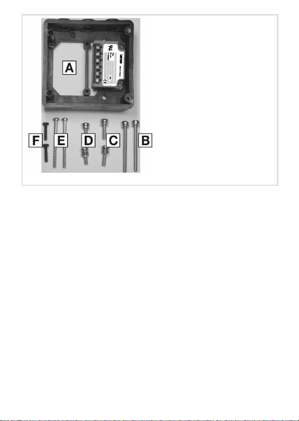
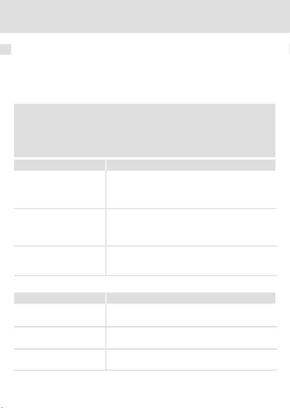
Lieferumfang
Pos. Beschreibung
E82ZMBRB (Gehäusewanne, Bremsenschalter E82ZWBRB vormontiert)
2 Schrauben M5 x 55 für Motormontage
2 Schrauben M5 x 16 für Motormontage
2 Schrauben M5 x 20
2 Selbstformschrauben 5 x 55 für Wandmontage
2 Selbstformschrauben 5 x 18 für Wandmontage
Montageanleitung
Tipp!
Aktuelle Dokumentationen und Software−Updates zu Lenze Produkten finden
Sie im Internet jeweils im Bereich "Services & Downloads" unter
http://www.Lenze.com
0Abb. 0Tab. 0
© 2008 Lenze Drive Systems GmbH, Hans−Lenze−Straße 1, D−31855 Aerzen
Ohne besondere schriftliche Genehmigung von Lenze Drive Systems GmbH darf kein Teil dieser Dokumentation vervielfältigt oder Dritten zugänglich gemacht werden.
Wir haben alle Angaben in dieser Dokumentation mit größter Sorgfalt zusammengestellt und auf
Übereinstimmung mit der beschriebenen Hard− und Software geprüft. Trotzdem können wir Abweichungen nicht ganz ausschließen. Wir übernehmen keine juristische Verantwortung oder Haftung für
Schäden, die dadurch eventuell entstehen. Notwendige Korrekturen werden wir in die nachfolgenden
Auflagen einarbeiten.
4
EDK82ZMBRB DE/EN/FR 1.0
Page 5

Inhalt i
1 Über diese Dokumentation 6 . . . . . . . . . . . . . . . . . . . . . . . . . . . . . . . . . . . . . . . . . .
Zielgruppe 6 . . . . . . . . . . . . . . . . . . . . . . . . . . . . . . . . . . . . . . . . . . . . . . . . . . . . . . . .
Informationen zur Gültigkeit 6 . . . . . . . . . . . . . . . . . . . . . . . . . . . . . . . . . . . . . . . . .
Dokumenthistorie 7 . . . . . . . . . . . . . . . . . . . . . . . . . . . . . . . . . . . . . . . . . . . . . . . . . .
Verwendete Konventionen 7 . . . . . . . . . . . . . . . . . . . . . . . . . . . . . . . . . . . . . . . . . .
Definition der verwendeten Hinweise 8 . . . . . . . . . . . . . . . . . . . . . . . . . . . . . . . . .
2 Sicherheitshinweise 10 . . . . . . . . . . . . . . . . . . . . . . . . . . . . . . . . . . . . . . . . . . . . . . . .
Allgemeine Sicherheits− und Anwendungshinweise 10 . . . . . . . . . . . . . . . . . . . . . .
Sicherheitshinweise für die Installation nach UL oder UR 11 . . . . . . . . . . . . . . . . . .
3 Technische Daten 12 . . . . . . . . . . . . . . . . . . . . . . . . . . . . . . . . . . . . . . . . . . . . . . . . . .
Allgemeine Daten / Einsatzbedingungen 12 . . . . . . . . . . . . . . . . . . . . . . . . . . . . . . .
Bemessungsdaten 14 . . . . . . . . . . . . . . . . . . . . . . . . . . . . . . . . . . . . . . . . . . . . . . . . . .
4 Mechanische Installation 15 . . . . . . . . . . . . . . . . . . . . . . . . . . . . . . . . . . . . . . . . . . . .
Motormontage 15 . . . . . . . . . . . . . . . . . . . . . . . . . . . . . . . . . . . . . . . . . . . . . . . . . . . .
Wandmontage 17 . . . . . . . . . . . . . . . . . . . . . . . . . . . . . . . . . . . . . . . . . . . . . . . . . . . .
5 Elektrische Installation 19 . . . . . . . . . . . . . . . . . . . . . . . . . . . . . . . . . . . . . . . . . . . . . .
EDK82ZMBRB DE/EN/FR 1.0
5
Page 6
1 Über diese Dokumentation
Zielgruppe
1 Über diese Dokumentation
Zielgruppe
Diese Dokumentation richtet sich an qualifiziertes Fachpersonal nach IEC 364.
Informationen zur Gültigkeit
Diese Dokumentation ist nur gültig:
ƒ zusammen mit der zugehörigen Dokumentation der für den Einsatz zulässigen
Grundgeräte.
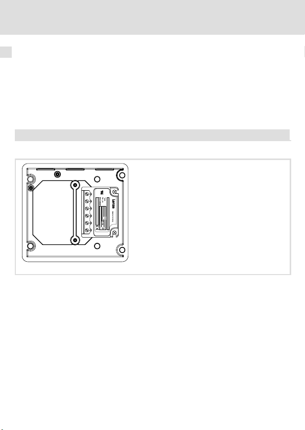
ƒ für Bremsenschalter ab der Typenschildbezeichnung:
E82ZMBRB
Identifikation
E82ZWBRB
Hardwarestand
82zwbrx_08
6
EDK82ZMBRB DE/EN/FR 1.0
Page 7
Über diese Dokumentation
Dokumenthistorie
Dokumenthistorie
Materialnummer Version Beschreibung
.6÷[ 1.0 02/2008 TD00 Erstausgabe
Verwendete Konventionen
Diese Dokumentation verwendet folgende Konventionen zur Unterscheidung verschiedener Arten von Information:
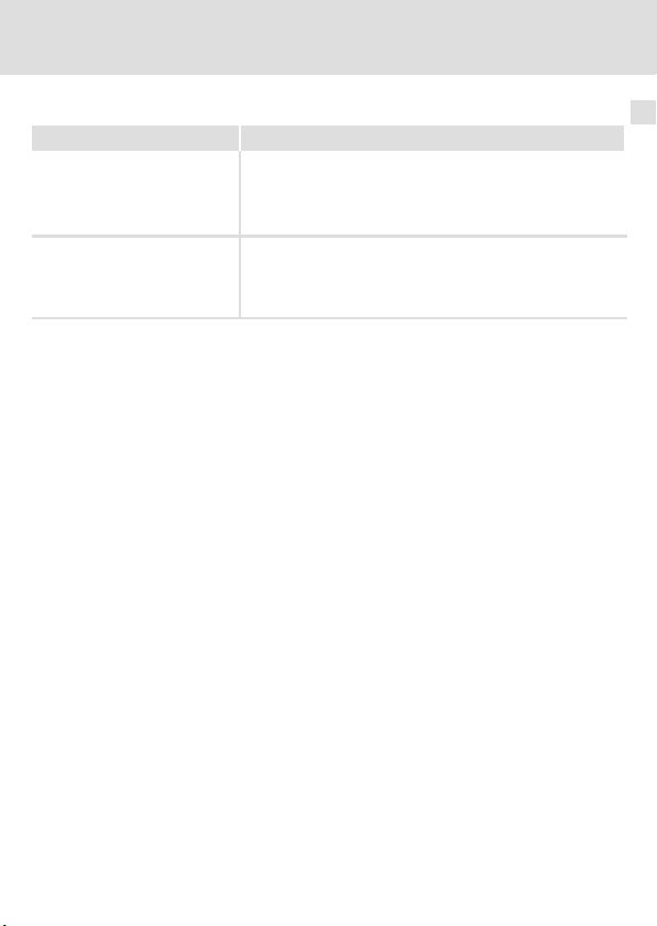
Informationsart Auszeichnung Beispiele/Hinweise
Zahlenschreibweise
Dezimaltrennzeichen
Warnhinweise
UL−Warnhinweise
UR−Warnhinweise
Textauszeichnung
Programmname » « Lenze Software
Symbole
Querverweis
Punkt Es wird generell der Dezimalpunkt
verwendet.
Zum Beispiel: 1234.56
Werden nur in der englischen Sprache
verwendet.
Zum Beispiel: »Engineer«
Weist auf zusätzliche Information
hin. Zum Beispiel
16 = s. Seite 16.
1
EDK82ZMBRB DE/EN/FR 1.0
7
Page 8
1 Über diese Dokumentation
Definition der verwendeten Hinweise
Definition der verwendeten Hinweise
Um auf Gefahren und wichtige Informationen hinzuweisen, werden in dieser Dokumentation folgende Piktogramme und Signalwörter verwendet:
Sicherheitshinweise
Aufbau der Sicherheitshinweise:
Gefahr!
(kennzeichnet die Art und die Schwere der Gefahr)
Hinweistext
(beschreibt die Gefahr und gibt Hinweise, wie sie vermieden werden kann)
Piktogramm und Signalwort Bedeutung
Gefahr von Personenschäden durch gefährliche elektrische Spannung
Gefahr!
Gefahr!
Stop!
Anwendungshinweise
Piktogramm und Signalwort Bedeutung
Hinweis auf eine unmittelbar drohende Gefahr, die den Tod oder
schwere Verletzungen zur Folge haben kann, wenn nicht die
entsprechenden Maßnahmen getroffen werden.
Gefahr von Personenschäden durch eine allgemeine Gefahrenquelle
Hinweis auf eine unmittelbar drohende Gefahr, die den Tod oder
schwere Verletzungen zur Folge haben kann, wenn nicht die
entsprechenden Maßnahmen getroffen werden.
Gefahr von Sachschäden
Hinweis auf eine mögliche Gefahr, die Sachschäden zur Folge
haben kann, wenn nicht die entsprechenden Maßnahmen getroffen werden.
Hinweis!
Tipp!
8
Wichtiger Hinweis für die störungsfreie Funktion
Nützlicher Tipp für die einfache Handhabung
Verweis auf andere Dokumentation
EDK82ZMBRB DE/EN/FR 1.0
Page 9
Über diese Dokumentation
Definition der verwendeten Hinweise
Spezielle Sicherheitshinweise und Anwendungshinweise für UL und UR
Piktogramm und Signalwort Bedeutung
Sicherheitshinweis oder Anwendungshinweis für den Betrieb
eines UL−approbierten Geräts in UL−approbierten Anlagen.
Warnings!
Warnings!
Möglicherweise wird das Antriebssystem nicht UL−gerecht betrieben, wenn nicht die entsprechenden Maßnahmen getroffen
werden.
Sicherheitshinweis oder Anwendungshinweis für den Betrieb
eines UR−approbierten Geräts in UL−approbierten Anlagen.
Möglicherweise wird das Antriebssystem nicht UL−gerecht betrieben, wenn nicht die entsprechenden Maßnahmen getroffen
werden.
1
EDK82ZMBRB DE/EN/FR 1.0
9
Page 10

2 Sicherheitshinweise
Allgemeine Sicherheits− und Anwendungshinweise
2 Sicherheitshinweise
Allgemeine Sicherheits− und Anwendungshinweise
Gefahr!
Gefährliche elektrische Spannung!
An den Anschlüssen des Bremsenschalters können gefährliche elektrische
Spannungen anliegen.
Mögliche Folgen:
ƒ Tod oder schwerste Verletzungen beim Berühren der Anschlussklemmen.
Schutzmaßnahmen:
ƒ Vor allen Arbeiten das Grundgerät und den Bremsenschalter vom Netz
trennen.
ƒ Alle Leistungsklemmen auf Spannungsfreiheit prüfen.
Stop!
Der elektronische Bremsenschalter beinhaltet einen elektronischen Schalter,
der eine Motorhaltebremse ansteuern kann.
Es dürfen nur Motorhaltebremsen angeschlossen werden, die den in den
Technischen Daten genannten zulässigen Daten entsprechen.
Werden die in den Technischen Daten genannten zulässigen Werte nicht
eingehalten:
ƒ kann die Motorbremsen−Ansteuerung zerstört werden.
ƒ ist ein sicherer Betrieb der Motorhaltebremse nicht gewährleistet.
Beachten Sie weitere Hinweise in der Dokumentation zum Grundgerät!
10
EDK82ZMBRB DE/EN/FR 1.0
Page 11

Sicherheitshinweise für die Installation nach UL oder UR
Sicherheitshinweise für die Installation nach UL oder U
Warnings!
ƒ Voltage of the fuses must at least be suitable with the input voltage.
ƒ Maximum surrounding air temperature: 55 °C with derating.
ƒ Load at "Brake Output" is provided for "dc pilot duty".
Sicherheitshinweise
2
R
EDK82ZMBRB DE/EN/FR 1.0
11
Page 12
3 Technische Daten
Allgemeine Daten / Einsatzbedingungen
3 Technische Daten
Allgemeine Daten / Einsatzbedingungen
Funktion
Der elektronische Bremsenschalter ermöglicht die Ansteuerung der elektromagnetischen
Haltebremse in einem Bremsmotor.
Einsetzbarkeit
Der elektronische Bremsenschalter ist ausschließlich einsetzbar mit Frequenzumrichtern
8200 motec, Typ E82MV251_2B oder E82MV371_2B.
Allgemeine Daten
Konformität und Approbation
Konformität
CE
Approbation
UR UL 508C Industrial Control Equipment Recognised
Personenschutz und Geräteschutz
Schutzart EN 60529
Schutzmaßnahmen Gegen Kurzschluss
EMV
Störaussendung EN 61800−3
Störfestigkeit EN 61800−3
73/23/EWG Niederspannungsrichtlinie
(File No. E132659) für USA
IP00
Leitungsgeführt, Kategorie C2.
Burst auf Netzleitung: 2 kV/5 kHz
Burst auf Steuerleitung: 2 kV/5 kHz
Surge auf Netzleitung:
1 kV (1.2 ms/50 ms;
Phase − Phase)
2 kV (1.2 ms/50 ms;
Phase − PE)
12
EDK82ZMBRB DE/EN/FR 1.0
Page 13
Allgemeine Daten / Einsatzbedingungen
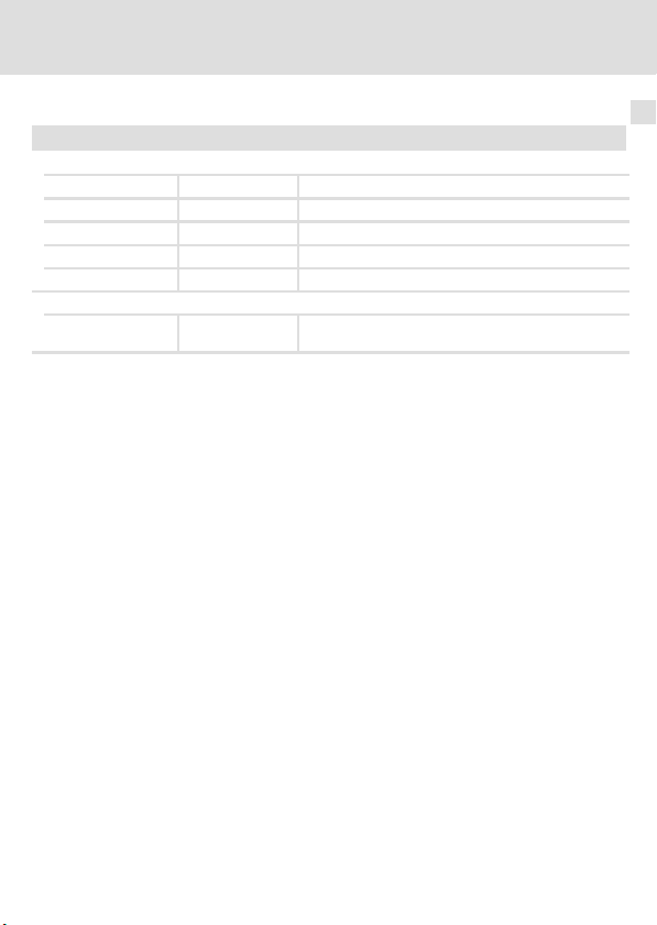
Einsatzbedingungen
Umgebungsbedingungen
Klimatisch
Lagerung
Transport IEC/EN 60721−3−2 2K3 (−25 ... +70 °C)
Betrieb IEC/EN 60721−3−3 3K3 (−10 ... +55 °C)
Verschmutzung EN 61800−5−1 Verschmutzungsgrad 2
Aufstellhöhe < 4000 m üNN
Mechanisch
Rüttelfestigkeit Germanischer
IEC/EN 60721−3−1 1K3 (−25 ... +60 °C)
Lloyd
Allgemeine Bedingungen
Beschleunigungsfest bis 2 g
Technische Daten
3
EDK82ZMBRB DE/EN/FR 1.0
13
Page 14
3 Technische Daten
Bemessungsdaten
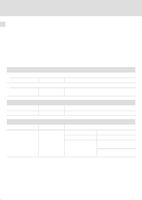
Bemessungsdaten
Bereich Werte
Eingangsspannung 1/N/PE AC 230 V (AC 180 ... 264 V), 45 ... 65 Hz
Eingangsstrom AC 0.1 ... 0.41 A
Ausgangsspannung
Maximaler Bremsenstrom
Steuereingang
Steuerspannung
Steuerstrom 5 ... 10 mA
Schutzfunktion Verpolungssicher bis DC 60 V
Maximal anschließbarer
Leitungsquerschnitt
Zulässige Schalthäufigkeiten
Empfohlene Bremse Leistung Spule: Spannung DC 205 V Zulässige Schalthäufigkeit
Typ P [W] L [H] I [A] (20 °C) [1/min]
BFK457−06E
BFK458−06E
BFK457−08E
BFK458−08E
2/PE AC 230 V (AC 180 ... 264 V), 45 ... 65 Hz
DC 205 V bei Netzspannung AC 230 V
DC 0.41 A
DC 24 V, SPS−Pegel
HIGH
LOW
1.5 mm
AWG 16
20
25 66 0.12 60
DC +15 ... 30 V
DC 0 ... +3 V
2
76 0.10 60
14
EDK82ZMBRB DE/EN/FR 1.0
Page 15
Mechanische Installation
Motormontage
4 Mechanische Installation
Motormontage
Vorbereitende Arbeiten
1. Motor−Klemmenkasten demontieren.
2. Motor−Klemmenbrett demontieren.
3. Die Motor−Anschlüsse müssen ca. 15 cm lang sein, ggf. verlängern.
4
8200mot139
EDK82ZMBRB DE/EN/FR 1.0
15
Page 16
4 Mechanische Installation
Motormontage
Montage
1. Gehäusewanne mit 2 Schrauben M5 x 16 auf den Motor schrauben.
82ZMBRB_05
82ZMBR1006
2. motec−Trägergehäuse mit 2 Schrauben M5 x 55 und 2 Schrauben M5 x 20 auf
die Gehäusewanne schrauben.
3. Bremsenschalter verdrahten. (19)
16
EDK82ZMBRB DE/EN/FR 1.0
Page 17
Mechanische Installation
Wandmontage
Vorbereitende Arbeiten
5.3 mm
96
110
71
85
1. Wandplatte (Lieferumfang des motec) an die Wand schrauben.
Wandmontage
4
82zmbrb_01
EDK82ZMBRB DE/EN/FR 1.0
17
Page 18
4 Mechanische Installation
Wandmontage
Montage
82ZMBRB_07
1. Gehäusewanne mit 2 Selbstformschrauben 5 x 18 auf die Wandplatte schrauben.
2. motec−Trägergehäuse mit 2 Selbstformschrauben 5 x 55 und 2 Schrauben
M5 x 20 auf die Gehäusewanne schrauben.
3. Bremsenschalter verdrahten. (19)
18
EDK82ZMBRB DE/EN/FR 1.0
82ZMBR1006
Page 19

5 Elektrische Installation
K10
L1
L2
L3
N
PE
F1
Elektrische Installation 5
3/PE AC 400 V
8200 motec
X1
L1 PE
L2/N
E82ZWBRB
BD1BD2 GI DIL2/N L1
+-
M
3~
DC 205 V (AC 230 V)
Legende siehe nächste Seite
EDK82ZMBRB DE/EN/FR 1.0
L3
}
BD1=+
BD2=-
E82ZMBRB
6mm
0.24 in
Z1
Z1
GI DI
GI DI
A1
K12
GND1GND1
7720
GND
7
K14K11
+20 V
59
Z1
+20 V
………
20
GND1
GND2
……
+20 V
720
A1
……
0
5939
1
2
82zwbrx_11
19
Page 20

5 Elektrische Installation
Anschlussvariante 1:
Z1 Funktionsmodul Standard−I/O
Die interne Spannungsquelle des Funktionsmoduls versorgt den Digitalausgang.
Ansteuerung des Bremsenschalters über den Digitalausgang des Funktionsmoduls.
Anschlussvariante 2:
Z1 Funktionsmodul Application−I/O
Die interne Spannungsquelle des Funktionsmoduls versorgt den Digitalausgang.
Ansteuerung des Bremsenschalters über den Digitalausgang des Funktionsmoduls.
Anschlussvariante 3 (nur mit 8200 motec, Variante V152 oder V153):
Z1 Funktionsmodul
Die interne Spannungsquelle des Funktionsmoduls versorgt den Digitalausgang des
motec.
Ansteuerung des Bremsenschalters über den Digitalausgang des motec.
Hinweis:
Statt über die interne Spannungsquelle des Funktionsmoduls können Sie den
Digitalausgang des motec auch über eine externe Spannungsquelle DC 24 V versorgen.
Klemmendaten
flexibel
mit Aderendhülse
20
Leiterquerschnitt Anzugsmoment
[mm2] [AWG] [Nm] [lb−in]
0.5 ... 1.5
20 ... 16 0.5 ... 0.6 4.5 ... 6.2
EDK82ZMBRB DE/EN/FR 1.0
Page 21

Notizen !
EDK82ZMBRB DE/EN/FR 1.0
21
Page 22

Scope of supply
Pos. Description
E82ZMBRB (Housing shell, pre−mounted brake switch E82ZWBRB)
2 screws M5 x 55 for motor mounting
2 screws M5 x 16 for motor mounting
2 screws M5 x 20
2 self−tapping screws 5 x 55 for wall mounting
2 self−tapping screws 5 x 18 for wall mounting
Mounting Instructions
Tip!
Current documentation and software updates concerning Lenze products can
be found on the Internet in the "Services & Downloads" area under
http://www.Lenze.com
0Fig. 0Tab. 0
© 2008 Lenze Drive Systems GmbH, Hans−Lenze−Straße 1, D−31855 Aerzen
No part of this documentation may be reproduced or made accessible to third parties without written
consent by Lenze Drive Systems GmbH.
All information given in this documentation has been selected carefully and complies with the
hardware and software described. Nevertheless, discrepancies cannot be ruled out. We do not take any
responsibility or liability for any damage that may occur. Necessary corrections will be included in
subsequent editions.
22
EDK82ZMBRB DE/EN/FR 1.0
Page 23

Contents i
1 About this documentation 24 . . . . . . . . . . . . . . . . . . . . . . . . . . . . . . . . . . . . . . . . . . .
Target group 24 . . . . . . . . . . . . . . . . . . . . . . . . . . . . . . . . . . . . . . . . . . . . . . . . . . . . . .
Validity information 24 . . . . . . . . . . . . . . . . . . . . . . . . . . . . . . . . . . . . . . . . . . . . . . . .
Document history 25 . . . . . . . . . . . . . . . . . . . . . . . . . . . . . . . . . . . . . . . . . . . . . . . . . .
Conventions used 25 . . . . . . . . . . . . . . . . . . . . . . . . . . . . . . . . . . . . . . . . . . . . . . . . . .
Definition of notes used 26 . . . . . . . . . . . . . . . . . . . . . . . . . . . . . . . . . . . . . . . . . . . . .
2 Safety instructions 28 . . . . . . . . . . . . . . . . . . . . . . . . . . . . . . . . . . . . . . . . . . . . . . . . .
General safety and application notes 28 . . . . . . . . . . . . . . . . . . . . . . . . . . . . . . . . . .
Safety instructions for the installation according to UL or UR 29 . . . . . . . . . . . . . . .
3 Technical data 30 . . . . . . . . . . . . . . . . . . . . . . . . . . . . . . . . . . . . . . . . . . . . . . . . . . . . .
General data/operating conditions 30 . . . . . . . . . . . . . . . . . . . . . . . . . . . . . . . . . . . .
Rated data 32 . . . . . . . . . . . . . . . . . . . . . . . . . . . . . . . . . . . . . . . . . . . . . . . . . . . . . . . .
4 Mechanical installation 33 . . . . . . . . . . . . . . . . . . . . . . . . . . . . . . . . . . . . . . . . . . . . .
Motor mounting 33 . . . . . . . . . . . . . . . . . . . . . . . . . . . . . . . . . . . . . . . . . . . . . . . . . . .
Wall mounting 35 . . . . . . . . . . . . . . . . . . . . . . . . . . . . . . . . . . . . . . . . . . . . . . . . . . . .
5 Electrical installation 37 . . . . . . . . . . . . . . . . . . . . . . . . . . . . . . . . . . . . . . . . . . . . . . .
EDK82ZMBRB DE/EN/FR 1.0
23
Page 24

1 About this documentation
Target group
1 About this documentation
Target group
This documentation is directed at qualified personnel according to IEC 364.
Validity information
This documentation is only valid:
ƒ together with the corresponding documentation for the standard devices permitted
for the application.
ƒ for brake switches with the below nameplate data or higher
E82ZMBRB
Identification
82zwbrx_08
E82ZWBRB
Hardware version
24
EDK82ZMBRB DE/EN/FR 1.0
Page 25

About this documentation
Document history
Document history
Material number Version Description
.6÷[ 1.0 02/2008 TD00 First edition
Conventions used
This documentation uses the following conventions to distinguish between different types
of information:
Type of information Writing Examples/notes
Notation of numbers
Decimal separator
Warnings
UL warnings
UR warnings
Text font style
Program name » « Lenze software
Symbols
Cross−reference
Point The decimal point is always used.
For example: 1234.56
Are only given in English.
For example: »Engineer«
Refers to additional information. For
example 16 = see page 16.
1
EDK82ZMBRB DE/EN/FR 1.0
25
Page 26

1 About this documentation
Definition of notes used
Definition of notes used
The following pictographs and signal words are used in this documentation to indicate
dangers and important information:
Safety instructions
Structure of safety instructions:
Danger!
(characterises the type and severity of danger)
Note
(describes the danger and gives information about how to prevent dangerous
situations)
Pictograph and signal word Meaning
Danger of personal injury through dangerous electrical voltage.
Danger!
Danger!
Stop!
Application notes
Pictograph and signal word Meaning
Reference to an imminent danger that may result in death or
serious personal injury if the corresponding measures are not
taken.
Danger of personal injury through a general source of danger.
Reference to an imminent danger that may result in death or
serious personal injury if the corresponding measures are not
taken.
Danger of property damage.
Reference to a possible danger that may result in property
damage if the corresponding measures are not taken.
Note!
Tip!
26
Important note to ensure troublefree operation
Useful tip for simple handling
Reference to another documentation
EDK82ZMBRB DE/EN/FR 1.0
Page 27

About this documentation
Definition of notes used
Special safety instructions and application notes for UL and UR
Pictograph and signal word Meaning
Safety or application note for the operation of a UL−approved
Warnings!
Warnings!
device in UL−approved systems.
Possibly the drive system is not operated in compliance with UL if
the corresponding measures are not taken.
Safety or application note for the operation of a UR−approved
device in UL−approved systems.
Possibly the drive system is not operated in compliance with UL if
the corresponding measures are not taken.
1
EDK82ZMBRB DE/EN/FR 1.0
27
Page 28

2 Safety instructions
General safety and application notes
2 Safety instructions
General safety and application notes
Danger!
Dangerous electrical voltage!
Dangerous electrical voltages may be applied to the connections of the brake
switch.
Possible consequences:
ƒ Death or severe injuries when touching the terminals.
Protective measures:
ƒ Disconnect the standard device and the brake switch from the mains
before carrying out any operations.
ƒ Check that all power terminals are deenergised.
Stop!
The electronic brake switch includes an electronic switch which can control a
motor holding brake.
The motor brake control module may only be connected to holding brakes
which correspond to the permissible data specified in the technical data.
If the permissible values specified in the technical data are not complied with:
ƒ The motor brake control module can be destroyed.
ƒ A safe operation of the motor holding brake cannot be guaranteed.
Further notes in the documentation of the standard device must be observed!
28
EDK82ZMBRB DE/EN/FR 1.0
Page 29

Safety instructions for the installation according to UL or UR
Safety instructions for the installation according to UL or U
Warnings!
ƒ Voltage of the fuses must at least be suitable with the input voltage.
ƒ Maximum surrounding air temperature: 55 °C with derating.
ƒ Load at "Brake Output" is provided for "dc pilot duty".
Safety instructions
2
R
EDK82ZMBRB DE/EN/FR 1.0
29
Page 30

3 Technical data
General data/operating conditions
3 Technical data
General data/operating conditions
Function
The electronic brake switch enables the control of the electromechanical holding brake in
a brake motor.
Application range
The electronic brake switch can be used together with 8200 motec frequency inverters of
type E82MV251_2B or E82MV371_2B.
General data
Conformity and approval
Conformity
CE
Approval
UR UL 508C Industrial Control Equipment Recognised
Protection of persons and equipment
Enclosure EN 60529
Protective measures Against short circuit
EMC
Noise emission EN 61800−3
Noise immunity EN 61800−3
73/23/EEC Low−Voltage Directive
(file no. E132659) for USA
IP00
Conducted, category C2.
Burst on mains cable: 2 kV/5 kHz
Burst on control cable: 2 kV/5 kHz
Surge on mains cable:
1 kV (1.2 ms/50 ms;
phase − phase)
2 kV (1.2 ms/50 ms;
phase − PE)
30
EDK82ZMBRB DE/EN/FR 1.0
Page 31

General data/operating conditions
Operating conditions
Ambient conditions
Climatic
Storage
Transport IEC/EN 60721−3−2 2K3 (−25 ... +70 °C)
Operation IEC/EN 60721−3−3 3K3 (−10 ... +55 °C)
Pollution EN 61800−5−1 Degree of pollution 2
Site altitude < 4000 m amsl
Mechanical
Vibration resistance Germanischer
IEC/EN 60721−3−1 1K3 (−25 ... +60 °C)
Lloyd
General conditions
Acceleration−resistant up to 2 g
Technical data
3
EDK82ZMBRB DE/EN/FR 1.0
31
Page 32

3 Technical data
Rated data
Rated data
Area Values
Input voltage 1/N/PE AC 230 V (AC 180 ... 264 V), 45 ... 65 Hz
Input current AC 0.1 ... 0.41 A
Output voltage
Maximum brake current
Control input
Control voltage
Control current 5 ... 10 mA
Protective function Protected against polarity reversal up to DC 60 V
Maximum connectable
cable cross−section
Permissible switching rates
Recommended brake Power Coil: voltage DC 205 V Permissible switching rate
Type P [W] L [H] I [A] (20 °C) [1/min]
BFK457−06E
BFK458−06E
BFK457−08E
BFK458−08E
2/PE AC 230 V (AC 180 ... 264 V), 45 ... 65 Hz
DC 205 V with mains voltage AC 230 V
DC 0.41 A
DC 24 V, PLC level
HIGH
LOW
1.5 mm
AWG 16
20
25 66 0.12 60
DC +15 ... 30 V
DC 0 ... +3 V
2
76 0.10 60
32
EDK82ZMBRB DE/EN/FR 1.0
Page 33

Mechanical installation
Motor mounting
4 Mechanical installation
Motor mounting
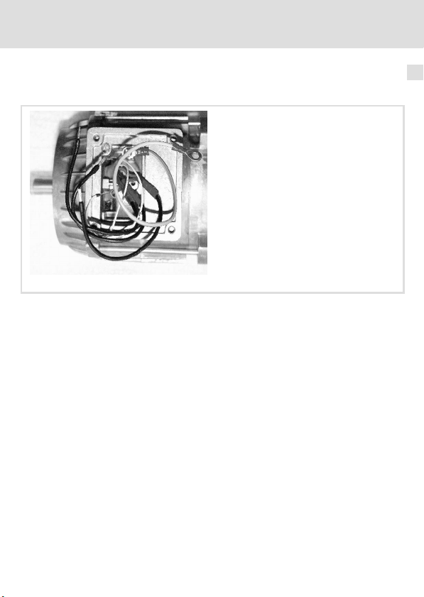
Preliminary works
8200mot139
1. Dismount motor terminal box.
2. Dismount motor terminal board.
3. The motor connections must be approx. 15 cm long, if necessary, extend them.
4
EDK82ZMBRB DE/EN/FR 1.0
33
Page 34

4 Mechanical installation
Motor mounting
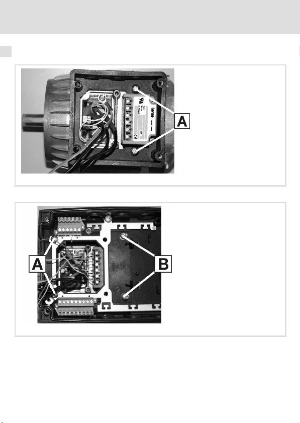
Mounting
1. Screw the housing shell to the motor with 2 screws M5 x 16 .
82ZMBRB_05
82ZMBR1006
2. Mount the motec carrier housing to the housing shell using 2 M5 x 55 screws and
2 M5 x 20 screws .
3. Wire brake switch. (
34
37)
EDK82ZMBRB DE/EN/FR 1.0
Page 35

Mechanical installation
Wall mounting
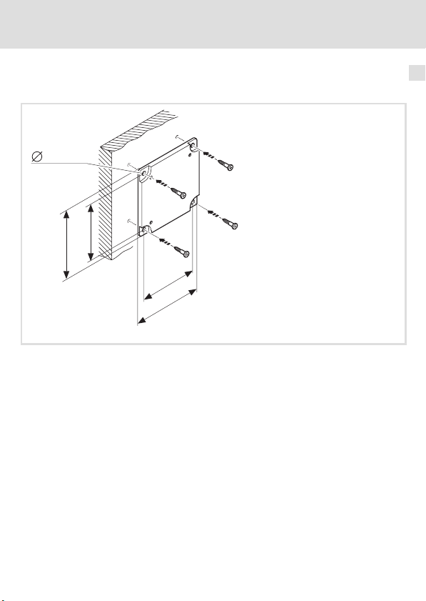
Preliminary works
5.3 mm
96
110
71
85
1. Screw the mounting plate (supplied with the motec) to the wall.
Wall mounting
4
82zmbrb_01
EDK82ZMBRB DE/EN/FR 1.0
35
Page 36

4 Mechanical installation
Wall mounting
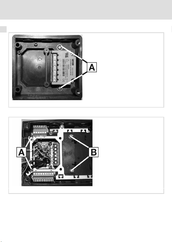
Mounting
1. Mount the housing shell to the mounting plate using the 2 self−tapping screws
5 x 18 .
82ZMBRB_07
82ZMBR1006
2. Mount the motec carrier housing to the housing shell using 2 5 x 55 self−tapping
screws and 2 M5 x 20 screws .
3. Wire brake switch. (
36
37)
EDK82ZMBRB DE/EN/FR 1.0
Page 37

5 Electrical installation
K10
L1
L2
L3
N
PE
F1
Electrical installation 5
3/PE AC 400 V
8200 motec
X1
L1 PE
L2/N
E82ZWBRB
BD1BD2 GI DIL2/N L1
+-
M
3~
DC 205 V (AC 230 V)
For legend see next page
EDK82ZMBRB DE/EN/FR 1.0
L3
}
BD1=+
BD2=-
E82ZMBRB
6mm
0.24 in
Z1
Z1
GI DI
GI DI
A1
K12
GND1GND1
7720
GND
7
K14K11
+20 V
59
Z1
+20 V
………
20
GND1
GND2
……
+20 V
720
A1
……
0
5939
1
2
82zwbrx_11
37
Page 38

5 Electrical installation
Connection variant 1:
Z1 Standard I/O function module
The internal voltage source of the function module supplies the digital output.
Control of the brake switch via the digital output of the function module.
Connection variant 2:
Z1 Application I/O function module
The internal voltage source of the function module supplies the digital output.
Control of the brake switch via the digital output of the function module.
Connection variant 3 (only with 8200 motec, variant V152 or V153):
Z1 Function module
The internal voltage source of the function module supplies the digital output of the
motec.
Control of the brake switch via the digital output of the motec.
Note:
Instead of using the internal voltage source of the function module, you can also supply
the digital output of the motec via an external 24 V DC voltage source.
Terminal data
Flexible
With wire end
ferrule
38
Conductor cross−section Tightening torque
[mm2] [AWG] [Nm] [lb−in]
0.5 ... 1.5 20 ... 16 0.5 ... 0.6 4.5 ... 6.2
EDK82ZMBRB DE/EN/FR 1.0
Page 39

Notes !
EDK82ZMBRB DE/EN/FR 1.0
39
Page 40

Equipement livré
Pos. Description
E82ZMBRB (Enveloppe, contacteur de frein électronique E82ZWBRB prémonté)
2 vis M5 x 55 pour la version "montage sur le moteur"
2 vis M5 x 16 pour la version "montage sur le moteur"
2 vis M5 x 20
2 vis autotaraudeuses 5 x 55 pour la version "montage au mur"
2 vis autotaraudeuses 5 x 18 pour la version "montage au mur"
Instructions de montage
Conseil !
Les mises à jour de logiciels et les documentations récentes relatives aux
produits Lenze sont disponibles dans la zone "Téléchargements" du site
Internet :
http://www.Lenze.com
0Fig. 0Tab. 0
© 2008 Lenze Drive Systems GmbH, Hans−Lenze−Straße 1, D−31855 Aerzen
Toute représentation ou reproduction, en tout ou en partie et par quelque procédé que ce soit, est
illicite sans l’autorisation écrite préalable de Lenze Drive Systems GmbH.
Les données figurant dans le présent fascicule ont été établies avec le plus grand soin et leur conformité
avec le matériel et le logiciel décrits a été vérifiée. Des divergences ne peuvent toutefois pas être
totalement exclues. Nous ne saurions être tenus responsables pour tout dommage qui pourrait
éventuellement en découler. Les corrections nécessaires seront intégrées dans les éditions suivantes.
40
EDK82ZMBRB DE/EN/FR 1.0
Page 41

Sommaire i
1 A propos de ce document 42 . . . . . . . . . . . . . . . . . . . . . . . . . . . . . . . . . . . . . . . . . . . .
Groupe cible 42 . . . . . . . . . . . . . . . . . . . . . . . . . . . . . . . . . . . . . . . . . . . . . . . . . . . . . .
Informations relatives à la validité 42 . . . . . . . . . . . . . . . . . . . . . . . . . . . . . . . . . . . .
Historique du document 43 . . . . . . . . . . . . . . . . . . . . . . . . . . . . . . . . . . . . . . . . . . . . .
Conventions utilisées 43 . . . . . . . . . . . . . . . . . . . . . . . . . . . . . . . . . . . . . . . . . . . . . . .
Définition des conventions utilisées 44 . . . . . . . . . . . . . . . . . . . . . . . . . . . . . . . . . . .
2 Consignes de sécurité 46 . . . . . . . . . . . . . . . . . . . . . . . . . . . . . . . . . . . . . . . . . . . . . . .
Instructions générales de sécurité et d’utilisation 46 . . . . . . . . . . . . . . . . . . . . . . . .
Consignes de sécurité pour l’installation selon UL ou UR 47 . . . . . . . . . . . . . . . . . .
3 Spécifications techniques 48 . . . . . . . . . . . . . . . . . . . . . . . . . . . . . . . . . . . . . . . . . . .
Caractéristiques générales/conditions d’utilisation 48 . . . . . . . . . . . . . . . . . . . . . .
Caractéristiques nominales 50 . . . . . . . . . . . . . . . . . . . . . . . . . . . . . . . . . . . . . . . . . .
4 Installation mécanique 51 . . . . . . . . . . . . . . . . . . . . . . . . . . . . . . . . . . . . . . . . . . . . . .
Montage sur le moteur 51 . . . . . . . . . . . . . . . . . . . . . . . . . . . . . . . . . . . . . . . . . . . . . .
Fixation murale 53 . . . . . . . . . . . . . . . . . . . . . . . . . . . . . . . . . . . . . . . . . . . . . . . . . . . .
5 Installation électrique 55 . . . . . . . . . . . . . . . . . . . . . . . . . . . . . . . . . . . . . . . . . . . . . . .
EDK82ZMBRB DE/EN/FR 1.0
41
Page 42

1 Présentation de la documentation
Groupe cible
1 A propos de ce document
Groupe cible
Ce document s’adresse à du personnel qualifié et habilité selon la norme CEI 364.
Informations relatives à la validité
Ce document est uniquement valable :
ƒ avec la documentation relative aux appareils de base compatibles,
ƒ pour les contacteurs de frein à partir de la version suivante (voir plaque
signalétique) :
E82ZMBRB
Identification
E82ZWBRB
Version matérielle
82zwbrx_08
42
EDK82ZMBRB DE/EN/FR 1.0
Page 43

Présentation de la documentation
Historique du document
Historique du document
Numéro de matériel Version Description
.6÷[ 1.0 02/2008 TD00 Première édition
Conventions utilisées
Pour distinguer entre différents types d’informations, ce document utilise les conventions
suivantes :
Type d’information Symbole Exemples/explications
Représentation des chiffres
Séparateur décimal
Consignes préventives
Consignes préventives UL
Consignes préventives UR
Mise en évidence de texte
Nom du programme » « Logiciel Lenze
Pictogrammes
Référence croisée
Point On utilise généralement le point
comme séparateur décimal.
Par exemple : 1234.56
Uniquement en anglais
Par exemple : »Engineer«
Renvoie à des informations
complémentaires. Par exemple,
= voir page 16.
16
1
EDK82ZMBRB DE/EN/FR 1.0
43
Page 44

1 Présentation de la documentation
Définition des conventions utilisées
Définition des conventions utilisées
Pour indiquer des risques et des informations importantes, la présente documentation
utilise les mots et symboles suivants :
Consignes de sécurité
Présentation des consignes de sécurité
Danger !
(Le pictogramme indique le type de risque.)
Explication
(L’explication décrit le risque et les moyens de l’éviter.)
Pictogramme et mot associé Explication
Situation dangereuse pour les personnes en raison d’une tension
électrique élevée
Danger !
Danger !
Stop !
Indication d’un danger imminent qui peut avoir pour
conséquences des blessures mortelles ou très graves en cas de
non−respect des consignes de sécurité correspondantes
Situation dangereuse pour les personnes en raison d’un danger
d’ordre général
Indication d’un danger imminent qui peut avoir pour
conséquences des blessures mortelles ou très graves en cas de
non−respect des consignes de sécurité correspondantes
Risques de dégâts matériels
Indication d’un risque potentiel qui peut avoir pour
conséquences des dégâts matériels en cas de non−respect des
consignes de sécurité correspondantes
44
EDK82ZMBRB DE/EN/FR 1.0
Page 45

Présentation de la documentation
Consignes d’utilisation
Pictogramme et mot associé Explication
Définition des conventions utilisées
1
Remarque
Remarque importante pour assurer un fonctionnement correct
importante !
Conseil !
Consignes de sécurité et d’utilisation spécifiques selon UL et UR
Pictogramme et mot associé Signification
Warnings !
Warnings !
Conseil utile pour faciliter la mise en oeuvre
Référence à une autre documentation
Consigne de sécurité ou d’utilisation pour le fonctionnement
d’un appareil homologué UL dans des installations homologuées
UL
Le système d’entraînement risque de ne pas être utilisé selon les
directives UL si des mesures correspondantes ne sont pas
prévues.
Consigne de sécurité ou d’utilisation pour le fonctionnement
d’un appareil homologué UR dans des installations homologuées
UL
Le système d’entraînement risque de ne pas être utilisé selon les
directives UL si des mesures correspondantes ne sont pas
prévues.
EDK82ZMBRB DE/EN/FR 1.0
45
Page 46

2 Consignes de sécurité
Instructions générales de sécurité et d’utilisation
2 Consignes de sécurité
Instructions générales de sécurité et d’utilisation
Danger !
Tension électrique dangereuse !
Des tensions électriques dangereuses peuvent circuler dans les raccordements
du contacteur de frein.
Risques encourus :
ƒ Mort ou blessures très graves en cas de contact accidentel avec les bornes
de raccordement.
Mesures de protection :
ƒ Couper l’appareil de base et le contacteur de frein du réseau avant tous
travaux.
ƒ S’assurer que toutes les bornes de puissance sont hors tension.
Stop !
Le contacteur de frein électronique comprend un interrupteur électronique
permettant de piloter un frein de parking.
Seuls des freins de parking respectant les données indiquées dans les
spécifications techniques peuvent être raccordés au module de pilotage du
frein de parking.
Si les valeurs indiquées dans les spécifications techniques ne sont pas
respectées
ƒ le module de pilotage du frein de parking risque d’être détruit,
ƒ le fonctionnement sûr du frein de parking n’est pas garanti.
Tenir compte des indications contenues dans la documentation de l’appareil
de base !
46
EDK82ZMBRB DE/EN/FR 1.0
Page 47

Consignes de sécurité pour l’installation selon UL ou UR
Consignes de sécurité pour l’installation selon UL ou U
Warnings !
ƒ Voltage of the fuses must at least be suitable with the input voltage.
ƒ Maximum surrounding air temperature: 55 °C with derating.
ƒ Load at "Brake Output" is provided for "dc pilot duty".
Consignes de sécurité
2
R
EDK82ZMBRB DE/EN/FR 1.0
47
Page 48

3 Spécifications techniques
Caractéristiques générales/conditions d’utilisation
3 Spécifications techniques
Caractéristiques générales/conditions d’utilisation
Fonction
Le contacteur de frein électronique permet de piloter le frein de parking électromagnétique
intégré dans un moteur−frein.
Utilisation
Le contacteur de frein électronique est destiné à une utilisation exclusive avec des
convertisseurs de fréquence motec, type E82MV251_2B ou E82MV371_2B.
Caractéristiques générales
Conformité et homologation
Conformité
CE
Homologation
UR UL 508C Industrial Control Equipment Recognised
Protection des personnes et protection d’appareil
Indice de protection EN 60529
Mesures de protection Contre les courts−circuits
CEM
Perturbations
radioélectriques :
émission
Protection contre les
parasites
73/23/CEE Directive Basse Tension
(File No. E132659) pour les Etas−Unis
IP00
EN 61800−3
EN 61800−3
Conduites par câbles, catégorie C2.
Transitoires rapides en
salves : câble réseau
Transitoires rapides en
salves : câble de
commande
Ondes de chocs : câble
réseau
2 kV/5 kHz
2 kV/5 kHz
1 kV (1.2 ms/50 ms ;
phase − phase)
2 kV (1.2 ms/50 ms ;
phase − PE)
48
EDK82ZMBRB DE/EN/FR 1.0
Page 49

Caractéristiques générales/conditions d’utilisation
Spécifications techniques
Conditions d’utilisation
Conditions ambiantes
Conditions climatiques
Stockage
Transport CEI/EN 60721−3−2 Classe 2K3 (−25 ... +70 °C)
Fonctionnement CEI/EN 60721−3−3 Classe 3K3 (−10 ... +55 °C)
Pollution ambiante
admissible
Altitude
d’implantation
Mécanique
Résistance aux chocs Germanischer
CEI/EN 60721−3−1 Classe 1K3 (−25 ... +60 °C)
EN 61800−5−1 Degré de pollution 2
< 4000 m au−dessus du niveau de la mer
Lloyd
Conditions générales
Résistance à l’accélération jusqu’à 2 g
3
EDK82ZMBRB DE/EN/FR 1.0
49
Page 50

3 Spécifications techniques
Caractéristiques nominales
Caractéristiques nominales
Domaine Valeurs
Tension d’entrée 1/N/PE 230 V CA (180 ... 317 V CA), 45 ... 65 Hz
Courant d’entrée 0.1 ... 0.41 A CA
Tension de sortie
Courant de freinage maxi
Entrée de commande
Tension de commande
Courant de commande 5 ... 10 mA
Fonction de protection Protection contre une possibilité d’inversion de polarité jusqu’à 60 V CC
Section de câble maxi
connectable
Fréquences de manoeuvre admissibles
Frein recommandé Puissance Bobine : tension de 205 V CC Fréquence de manoeuvre
Type P [W] L [H] I [A] (20 °C) [1/min]
BFK457−06E
BFK458−06E
BFK457−08E
BFK458−08E
2/PE 230 V CA (180 ... 317 V CA), 45 ... 65 Hz
205 V CC Pour une tension réseau de 230 V CA
0.41 A CC
24 V CC, niveau API
HAUT
BAS
1.5 mm
20
25 66 0.12 60
+15 ... 30 V CC
0 ... +3 V CC
2
76 0.10 60
admissible
50
EDK82ZMBRB DE/EN/FR 1.0
Page 51

Installation mécanique
Montage sur le moteur
4 Installation mécanique
Montage sur le moteur
Préparatifs
8200mot139
1. Démonter la boîte à bornes du moteur.
2. Démonter la planchette à bornes du moteur.
3. La longueur minimale des câbles moteur est env. 15 cm. Le cas échéant, les prolonger.
4
EDK82ZMBRB DE/EN/FR 1.0
51
Page 52

4 Installation mécanique
Montage sur le moteur
Montage
1. Visser l’enveloppe sur le moteur à l’aide de 2 vis M5 x 16 .
82ZMBRB_05
2. Visser le boîtier motec sur l’enveloppe à l’aide de 2 vis M5 x 55 et de 2 vis
M5 x 20 .
3. Câbler le contacteur de frein. (
52
55)
EDK82ZMBRB DE/EN/FR 1.0
82ZMBR1006
Page 53

Installation mécanique
Fixation murale
Fixation murale
Préparatifs
5.3 mm
96
110
71
85
1. Monter la plaque de montage (comprise dans l’équipement du motec) au mur.
4
82zmbrb_01
EDK82ZMBRB DE/EN/FR 1.0
53
Page 54

4 Installation mécanique
Fixation murale
Montage
1. Visser l’enveloppe sur la plaque de montage à l’aide de 2 vis autotaraudeuses
5 x 18 .
82ZMBRB_07
82ZMBR1006
2. Visser le boîtier motec sur l’enveloppe à l’aide de 2 vis autotaraudeuses 5 x 55 et de
2 vis M5 x 20 .
3. Câbler le contacteur de frein. (
54
55)
EDK82ZMBRB DE/EN/FR 1.0
Page 55

5 Installation électrique
K10
L1
L2
L3
N
PE
F1
Installation électrique 5
3/PE AC 400 V
8200 motec
L3
X1
L1 PE
L2/N
E82ZWBRB
BD1BD2 GI DIL2/N L1
BD1=+
+-
}
BD2=-
M
3~
DC 205 V (AC 230 V)
Voir légende sur la page suivante
EDK82ZMBRB DE/EN/FR 1.0
E82ZMBRB
6mm
0.24 in
Z1
Z1
GI DI
GI DI
A1
K12
GND1GND1
7720
GND
7
K14K11
+20 V
59
Z1
+20 V
………
20
GND1
GND2
……
+20 V
720
A1
……
0
5939
1
2
82zwbrx_11
55
Page 56

5 Installation électrique
Variante de raccordement 1 :
Z1 Module de fonction E/S standard
Alimentation de la sortie numérique via source de tension interne du module de
fonction.
Pilotage du contacteur de frein via la sortie numérique du module de fonction.
Variante de raccordement 2 :
Z1 Module de fonction E/S application
Alimentation de la sortie numérique via source de tension interne du module de
fonction.
Pilotage du contacteur de frein via la sortie numérique du module de fonction.
Variante de raccordement 3 (uniquement avec 8200 motec, variante V152 ou V153) :
Z1 Module de fonction
Alimentation de la sortie numérique du motec via source de tension interne du module
de fonction.
Pilotage du contacteur de frein via la sortie numérique du motec.
Remarque :
Plutôt que par la source de tension interne du module de fonction, la sortie numérique
du motec peut aussi être alimentée par une source de tension externe 24 V CC.
Spécifications des
bornes
flexible
avec embouts
56
Section de câble Couple de serrage
[mm2] [AWG] [Nm] [lb−in]
0.5 ... 1.5
20 ... 16 0.5 ... 0.6 4.5 ... 6.2
EDK82ZMBRB DE/EN/FR 1.0
Page 57

Notes !
EDK82ZMBRB DE/EN/FR 1.0
57
Page 58

Lenze Drive Systems GmbH
Hans−Lenze−Straße 1
D−31855 Aerzen
Germany
(
( Service
Ê Service
E−Mail Lenze@Lenze.de
Internet www.Lenze.com
+49(0)515482−0
00 80 00 24 4 68 77 (24 h helpline)
+49(0)51 5482−1112
EDK82ZMBRB
DE/EN/FR 1.0
© 02/2008
TD00
10987654321
 Loading...