

Page 1
EDK82ZMBR1
13200520
03/2011
Diese Anleitung
y enthält die wesentlichen Technischen Daten und beschreibt die Installation, die Handhabung und
die Inbetriebnahme des Bremsgleichrichters.
y ist nur gültig
- für Bremsgleichrichter mit der Typenschildbezeichnung E82ZMBR1
- zusammen mit der Montageanleitung des Frequenzumrichters 8200 motec
Beschreibung
Der Bremsgleichrichter ermöglicht die Ansteuerung der elektromagnetischen Haltebremse in einem
Bremsmotor mit Frequenzumrichter 8200 motec.
Einsatzbereich
Der Bremsgleichrichter E82ZMBR1 ist ausschließlich einsetzbar mit Frequenzumrichtern motec, Typ
E82MV251_2B oder E82MV371_2B.
Technische Daten
Ausführung y Brückengleichrichter
max. Anschlußspannung Uin= 250 V AC
Ausgangsspannung 0,9 x UinDC
max. Ausgangsstrom 0,75 A DC
Temperaturbereich (Lagerung) -25°C...+80°C
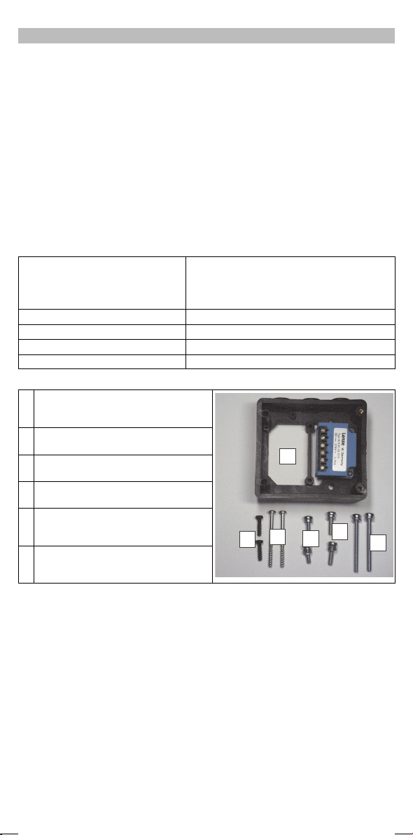
Lieferumfang
Gehäusewanne für Bremsgleichrichter,
Bremsgleichrichter vormontiert
2SchraubenM5x55fürMotormontage
Bremsgleichrichter E82ZMBR1
für 8200 motec 0,25/0,37 kW
y Eingang und Ausgang gegen Überspannung
geschützt
y Funkenlöschglied integriert
2SchraubenM5x16fürMotormontage
2SchraubenM5x20
2 Selbstformschrauben 5 x 55 für
Wandmontage
2 Selbstformschrauben 5 x 18 für
Wandmontage
Lenze Drives GmbH, Postfach 10 13 52, D-31763 Hameln
l
(+49) 5154 82-0, Fax Service: (+49) 5154 82-1112
5
82ZMBR1004
4
0
3
2
1
bahUOwj_oN 3.2
qaMM
Page 2
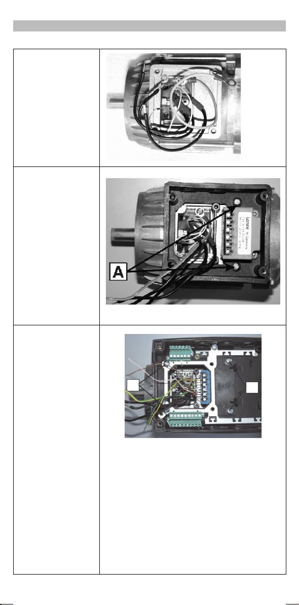
1. Motor vorbereiten (nur bei
Motormontage)
A Motor-Klemmkasten
demontieren
B Motor-Klemmbrett
demontieren
C Motor-Anschlüsse müssen
ca. 15 cm lang sein, ggf.
verlängern
2.
y Motormontage
- Gehäusewanne mit
2SchraubenM5x16
auf den Motor schrauben
y Wandmontage:
- Wandplatte (Liefer-
umfang des motec) an
die Wand schrauben
- Gehäusewanne mit 2
Selbstformschrauben
5x18aufdie
Wandplatte schrauben
3. Klemmen des
Bremsgleichrichters je
nach Schaltungsart
belegen ( 3)
4.
y Motormontage
- motec-Trägergehäuse
mit 2 Schrauben M5 x
55 und 2 Schrauben
M5 x 20 auf die
Gehäusewanne
schrauben
y Wandmontage:
- motec-Trägergehäuse
mit 2 Selbstformschrauben 5 x 55 und
2SchraubenM5x20
auf die Gehäusewanne
schrauben
5. Bremsgleichrichter je nach
Schaltungsart mit den
Klemmen des motec
verbinden ( 3)
Installation
0
8200mot139
82ZMBR1005
1
82ZMBR1006
6. Netz und Motor
anschließen (siehe
Montageanleitung
8200 motec)
7. Relaisausgang für
Bremsenansteuerung
konfigurieren! 5
l
-2-
bahUOwj_oN 3.2
qaMM
Page 3
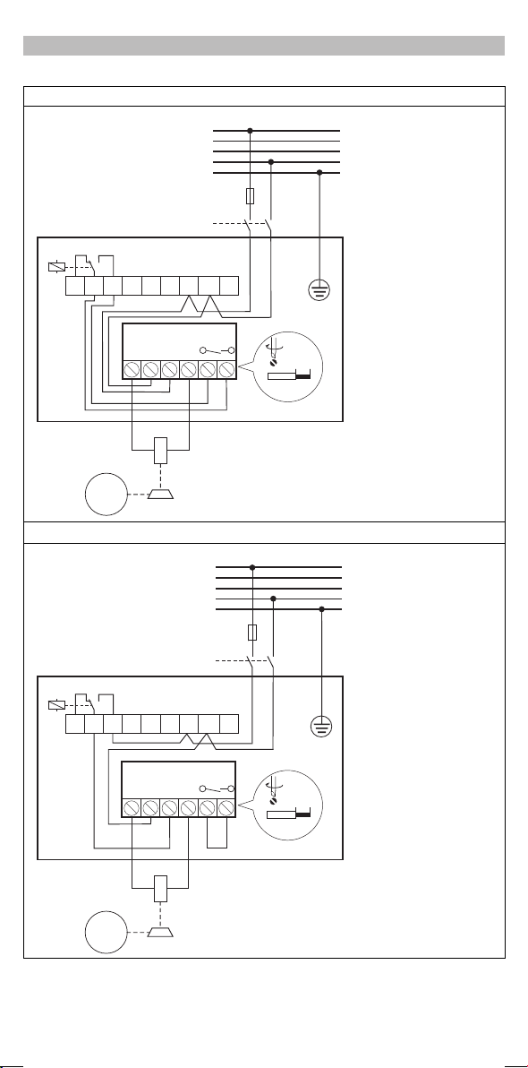
Verdrahtung
Gleichstromseitige Trennung (schnelles Einfallen der Bremse)
1/N/PE AC 180 V … 250 V
L1
L2
L3
N
PE
F1
K10
f < C0017 f C0017³
BR2K14 BR1K12K11
L2/N
L3
X1
-
M
3~
Wechselstromseitige Trennung (verzögertes Einfallen der Bremse)
f < C0017 f C0017³
L1
E82ZMBR1
+
~~
205 V
0.6 Nm / 5.3 lb-in
2
£ 1mm/AWG26...16
8200 motec
1/N/PE AC 180 V … 250 V
L1
L2
L3
N
PE
F1
K10
6 mm / 0.24 in
82ZMBR1001
X1
l
BR2K14 BR1K12K11
L2/N
L3
L1
E82ZMBR1
-
~~
0.6 Nm / 5.3 lb-in
6 mm / 0.24 in
2
£ 1mm/AWG26...16
+
8200 motec
M
3~
205 V
-3-
82ZMBR1002
bahUOwj_oN 3.2
qaMM
Page 4
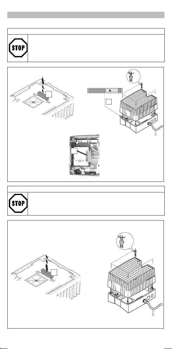
motec mit Funktionsmodul
y Vor dem Zusammenbau unbedingt Schutzkappe des Funktionsmoduls (B) und
FIF-Abdeckkappe (A) entfernen und aufbewahren! Sonst kann der motec beschädigt
werden!
y Vor Inbetriebnahme mit dem Aufkleber (C), der dem Funktionsmodul beiliegt, das
motec-Typenschild vervollständigen.
motec zusammenbauen
2.4 Nm
21 lbin
0
motec ohne Funktionsmodul
FIF-Abdeckkappe (A) muß aufgesteckt s ein. Der motec ist nur so funktionsfähig!
1
Standard-I/O
2
S
8200mot059
2.4 Nm
21 lbin
l
0
-4-
8200mot138
bahUOwj_oN 3.2
qaMM
Page 5
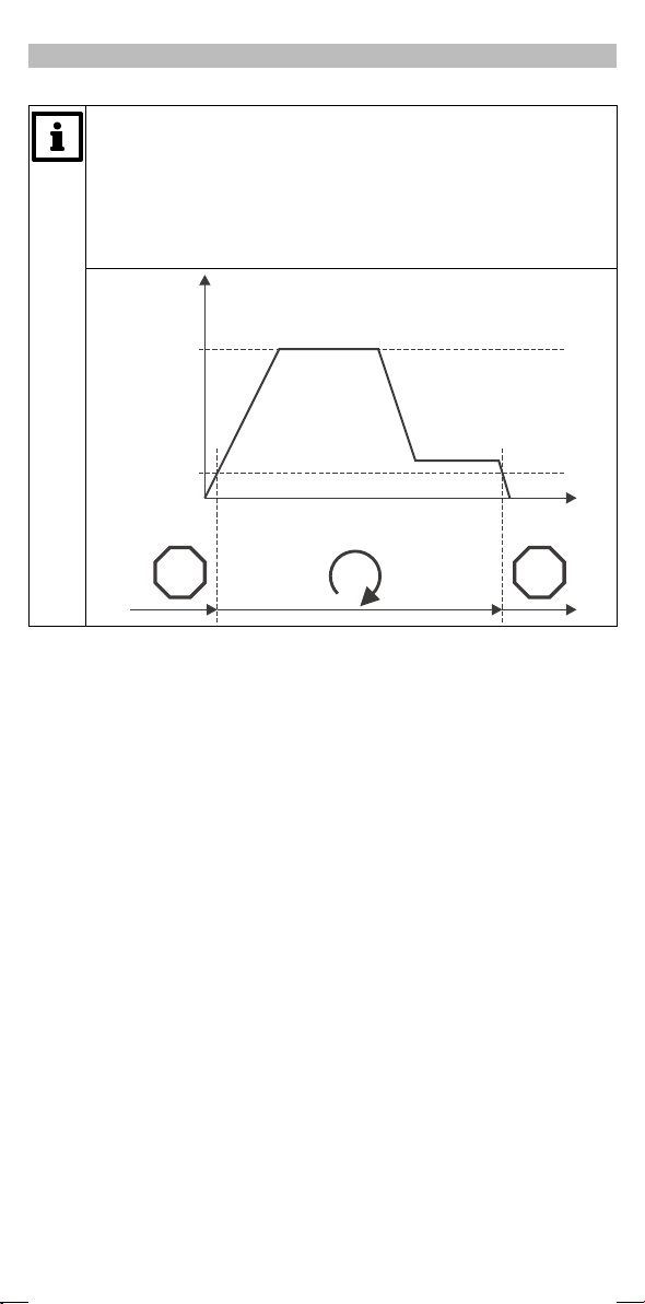
Inbetriebnahme
Vor der ersten Inbetriebnahme unbedingt
y den Relaisausgang für die Bremsenansteuerung konfigurieren
- Signal “Q
y die Frequenzschwelle Q
- die Bremse fällt ein, wenn der Sollwert Q
- die Bremse lüftet, wenn der Sollwert Q
y Alle anderen Inbetriebnahmeschritte entnehmen Sie der Montageanleitung des motec
bzw. der Montageanleitung eines verwendeten Funktionsmoduls.
-Schwelle unterschritten” dem Relaisausgang zuordnen mit C0008 = 7
min
einstellen mit C0017
min
min
überschreitet
min
unterschreitet
f[Hz]
f
max
(C0011)
Q
min
(C0017)
STOP STOP
t
82ZMBR1003
l
-5-
bahUOwj_oN 3.2
qaMM
Page 6

EDK82ZMBR1
13200520
03/2011
These Instructions
y contain the most important technical da ta, installation, handling and commissioning instructions
for the brake rectifier.
y are only valid
- for brake rectifiers with the nameplate data: E82ZMBR1
- together with the Mounting Instructions for the 8200 motec
Description
Brake rectifiers enablethe control of an electromagnetical holding brakein a brakemotor via a8200 motec
frequency inverter.
Range of application
The E82ZMBR1 brake rectifier is only applicable together with motec frequency inverters of type
E82MV251_2B or E82MV371_2B.
Technical data
Design y Bridge rectifier
Max. connection voltage Uin= 250 V AC
Output voltage 0.9 x UinDC
Max. output current 0.75 A DC
Temperature range (storage) -25°C...+80°C
Items supplied
Housing shell for brake rectifier, pre-mounted
brake rectifier
2 screws M5 x 55 for motor mounting
2 screws M5 x 16 for motor mounting
Brake rectifier E82ZMBR1
for 8200 motec 0.25/0.37 kW
y Input and output protected against overvoltage
y Integrated spark suppressor
0
2screwsM5x20
2 self-tapping screws 5 x 55 for wall mounting
2 self-tapping screws 5 x 18 for wall mounting
Lenze Drives GmbH, Postfach 10 13 52, D-31763 Hameln
l
(+49) 5154 82-0, Fax Service: (+49) 5154 82-1112
5
82ZMBR1004
4
2
3
bahUOwj_oN 3.2
1
qaMM
Page 7

1. Prepare motor (only for
motor mounting)
A Dismount motor terminal
box
B Dismount motor terminal
board
C The motor connections
must be approx. 15 cm
long, if necessary, extend
the cables
2.
y Motor mounting
- Screw the housing shell
to the motor with 2
screws M5 x 16
y Wall mounting:
- Screw the mounting
plate (part of the delivery
package of the motec) to
the wall
- Mount the housing shell
to the mounting plate
using the 2 self-tapping
screws 5 x 18
3. Assign the terminals of the
brake rectifier according to
theconnectiontype( 3)
4.
y Motor mounting
- Mount the motec carrier
housing to the housing
shell using 2 M5 x 55
screws and 2 M5 x 20
screws .
y Wall mounting:
- Mount the motec carrier
housing to the housing
shell using 2 5 x 55
self-tapping screws
and 2 M5 x 20
screws.
5. Connect the brake rectifier
to the motec terminals
according to the
connection type selected
( 3)
Installation
0
8200mot139
82ZMBR1005
1
6. Mains and motor
connection (see Mounting
Instructions for the 8200
motec)
7. Configure the relay output
for brake control! 5
l
-2-
bahUOwj_oN 3.2
qaMM
Page 8

DC switching (quick brake reaction)
L1
L2
L3
N
PE
F1
K10
f < C0017 f C0017³
BR2K14 BR1K12K11
L2/N
X1
L1
E82ZMBR1
+
~~
-
M
3~
205 V
AC switching (delayed brake reaction)
L1
L2
L3
N
PE
F1
K10
f < C0017 f C0017³
Wiring
1/N/PE AC 180 V … 250 V
L3
0.6 Nm / 5.3 lb-in
6 mm / 0.24 in
2
£ 1mm/AWG26...16
8200 motec
1/N/PE AC 180 V … 250 V
82ZMBR1001
X1
l
BR2K14 BR1K12K11
L2/N
L3
L1
E82ZMBR1
-
~~
0.6 Nm / 5.3 lb-in
6 mm / 0.24 in
2
£ 1mm/AWG26...16
+
8200 motec
M
3~
205 V
-3-
82ZMBR1002
bahUOwj_oN 3.2
qaMM
Page 9

motec with function module
y Remove and keep the protection cover of the f unction module (B) and the FIF
protection cover (A) before assembly! Otherwise, the motec can be damaged!
y Complete the motec nameplate with the sticker (C) that is delivered together with the
function module.
motec assembly
2.4 Nm
21 lbin
0
motec without function module
FIF protection cover (A) must be attached. Otherwise, t he motec is not ready for
operation!
1
Standard-I/O
2
S
8200mot059
2.4 Nm
21 lbin
l
0
-4-
8200mot138
bahUOwj_oN 3.2
qaMM
Page 10

Commissioning
Before commissioning
y configure the relay output for brake control
- Signal “Value below Q
setting C0008 = 7
y set the frequency threshold Q
- The brake is activated when the setpoint falls below Q
- The brake is released when the setpoint exceeds Q
y For more detailed information on commissioning, please see the Mounting
Instructions for the motec or the Mounting Instructions for the function module used.
f[Hz]
f
max
(C0011)
Q
min
(C0017)
STOP STOP
threshold ” must be assigned to the relay output by
min
under C0017
min
min
min
t
82ZMBR1003
l
-5-
bahUOwj_oN 3.2
qaMM
Page 11

EDK82ZMBR1
13200520
03/2011
Le présent fascicule
y contient les principales caractéristiques du redresseur frein et décrit son installation, sa
manipulation et sa mise en service.
y n’est valable que
- pour le redresseur frein type E82ZMBR1 (voir plaque signalétique),
- conjointement avec les instructions de montage du convertisseur de fréquence 8200 motec.
Description
Le redresseur frein permet de commander le frein de maintien électromagnétique pour un moteur-frein
d’un convertisseur de fréquence 8200 motec.
Domaine d’utilisation
Le redresseur freinE82ZMBR1 est destiné àune utilisation exclusiveavec des convertisseurs de fréquence
motec, type E82MV251_2B ou E82MV371_2B.
Spécifications techniques
Type de redresseur y Pont redresseur
Tension d’alimentation maxi Uin= 250 V CA
Ten s ion d e s ort i e 0,9 x UinCC
Tensiondesortiemaxi 0,75 A CC
Température ambiante (stockage) -25°C...+80°C
Equipement livré
Enveloppe pour redresseur frein ; redresseur
frein prémonté
2 vis M5 x 55 pour la version ”montage sur le
moteur”
2 vis M5 x 16 pour la version ”montage sur le
moteur”
2visM5x20
2 vis autotaraudeuses 5 x 55 pour la version
”montage au mur”
2 vis autotaraudeuses 5 x 18 pour la version
”montage au mur”
Redresseur frein E82ZMBR1
pour 8200 motec 0,25/0,37 kW
y Entrée et sortie protégées contre les surtensions
y Souffleur d’étincelles intégré
0
4
5
82ZMBR1004
3
2
1
l
Lenze Drives GmbH, Postfach 10 13 52, D-31763 Hameln
(+49) 5154 82-0, Fax Service: (+49) 5154 82-1112
bahUOwj_oN 3.2
qaMM
Page 12

1. Préparer le moteur (pour
montage sur le moteur
uniquement).
A Démonter la boîte à bornes
moteur.
B Démonter le bornier
moteur.
C Prévoir des câbles moteur
d’une longueur d’env.
15 cm ; le cas échéant, les
prolonger.
2.
y Montage sur le moteur
- Visser l’enveloppe sur le
moteuràl’aidede2vis
M5 x 16 .
y Montage au mur
- Visser la plaque de
montage (comprise dans
l’équipement motec) au
mur.
- Visser l’enveloppe sur la
plaque de montage à
l’aide de 2 vis
autotaraudeuses 5 x 18.
3. Affecter les bornes du
redresseur frein selon le
type de couplage ( 3 )
4.
y Montage sur le moteur
- Visser le boîtier motec
sur l’enveloppe à l’aide
de 2 vis M5 x 55 et
de 2 vis M5 x 20 .
y Montage au mur
- Visser le boîtier motec
sur l’enveloppe à l’aide
de 2 vis autotaraudeuses
M5 x 55 et de 2 vis
M5 x 20 .
5. Relier le redresseur frein
aux bornes du motec selon
le type de couplage
( 3).
Installation
0
8200mot139
1
6. Connecter le réseau et le
moteur (voir instructions
de montage 8200 motec).
7. Configurer la sortie relais
pour la commande frein !
5
l
-2-
bahUOwj_oN 3.2
qaMM
Page 13

Câblage
Coupure côté CC (enclenchement rapide du frein)
1/N/PE AC 180 V … 250 V
L1
L2
L3
N
PE
F1
K10
f < C0017 f C0017³
BR2K14 BR1K12K11
L2/N
L3
X1
-
M
3~
Coupure côté CA (retard de réponse à l’enclenchement du frein)
f < C0017 f C0017³
L1
E82ZMBR1
+
~~
205 V
0.6 Nm / 5.3 lb-in
2
£ 1mm/AWG26...16
8200 motec
1/N/PE AC 180 V … 250 V
L1
L2
L3
N
PE
F1
K10
6 mm / 0.24 in
82ZMBR1001
X1
l
BR2K14 BR1K12K11
L2/N
L3
L1
E82ZMBR1
-
~~
0.6 Nm / 5.3 lb-in
6 mm / 0.24 in
2
£ 1mm/AWG26...16
+
8200 motec
M
3~
205 V
-3-
82ZMBR1002
bahUOwj_oN 3.2
qaMM
Page 14

Assemblage du motec
motecavecmoduledefonction
y Avant l’assemblage, retirer impérativement le capot de protection du module de
fonction (B) et le capot de protection FIF (A) ! (Ne pas les jeter). Autrement, le motec
risque d’être détruit !
y Compléter la plaque signalétique motec à l’aide de l’autocollant (C) joint au module
de fonction.
2.4 Nm
21 lbin
0
motecsansmoduledefonction
Le capot de protection FIF (A) doit être enfiché. Autrement, la fonctionnalité du motec
n’est pas assurée !
1
Standard-I/O
2
S
8200mot059
2.4 Nm
21 lbin
l
0
-4-
8200mot138
bahUOwj_oN 3.2
qaMM
Page 15

Mise en service
Avant la première mise en service, procéder impérativement aux réglages suivants :
y Configurer la sortie relais pour la commande frein.
- Affecter le signal “ Seuil Q
y Régler le seuil de fréquence Q
- Le frein est enclenché dès que la valeur est inférieure à la consigne Q
- Le frein est débloqué dès que la valeur est supérieure à la consigne Q
y Pour les autres opérations de mise en service se reporter aux instructions de
montage du motec et aux instructions de montage du module de fonction utilisé.
f[Hz]
f
max
(C0011)
Q
min
(C0017)
STOP STOP
atteint” à la sortie relais en réglant C0008 = 7.
min
en C0017.
min
.
min
.
min
t
82ZMBR1003
l
-5-
bahUOwj_oN 3.2
qaMM
 Loading...