

Page 1
EDK82ZM113−002
.=7[
Ä.=7[ä
Global Drive
Montageanleitung
Mounting Instructions
Instructions de montage
8200 vector
E82ZM75134B, E82ZM22234B020, E82ZM40234B,
E82ZM75234B, E82ZM11334B
Motorfilter
Motor filter
Filtre moteur
l
Page 2

, Lesen Sie zuerst diese Anleitung und die Dokumentation zum Grundgerät,
bevor Sie mit den Arbeiten beginnen!
Beachten Sie die enthaltenen Sicherheitshinweise.
, Please read these instructions and the documentation of the standard
device before you start working!
Observe the safety instructions given therein!
, Lire le présent fascicule et la documentation relative à l’appareil de base
avant toute manipulation de l’équipement !
Respecter les consignes de sécurité fournies.
Page 3
2
0
1
3
E82ZM−011
Page 4
0Abb. 0Tab. 0
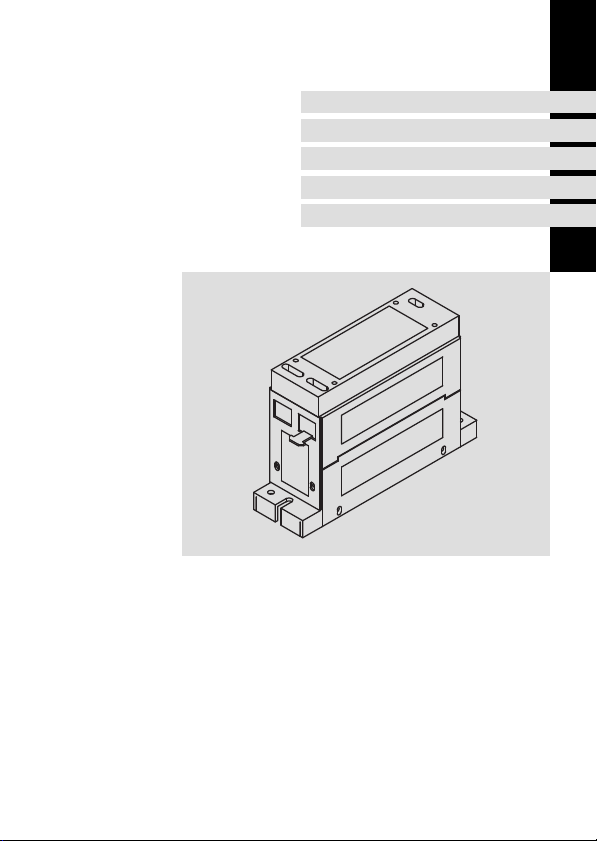
Lieferumfang
Anzahl Beschreibung
1 Filter
1 Montageanleitung
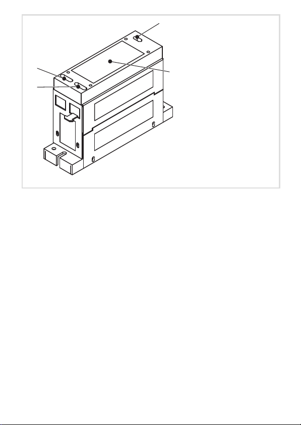
Elemente am Filter
Position Beschreibung
0
1
2
3
Anschlussklemmen Eingang (U, V, W, PE)
Anschlussklemmen Ausgang (U1, V1, W1, PE)
Anschlussklemmen Zwischenkreis (+UG, −UG)
Typenschild
Informationen zur Gültigkeit
Diese Anleitung ist gültig für
ƒ Motorfilter E82ZM75134B
ƒ Motorfilter E82ZM22234B020
ƒ Motorfilter E82ZM40234B
ƒ Motorfilter E82ZM75234B
ƒ Motorfilter E82ZM11334B
4
l
EDK82ZM113−002 DE/EN/FR 2.1
Page 5

Identifikation
l
Typ
Abb. 1 Typenschild
E82ZM−012
EDK82ZM113−002 DE/EN/FR 2.1
l
5
Page 6
Typenschlüssel
Produktreihe
Zubehör
Typ
M = motorseitiger Filter
E82 Z M xxx 3 x B xxx
Leistung
z. B. 752 = 75 x 10
z. B. 113 = 11 x 103 W = 11 kW
Anzahl Phasen
3 = 3 Phasen
Spannungsklasse
2 = 230 V
4 = 400/500 V
Gerätegeneration
Variante
2
W = 7,5 kW
6
l
EDK82ZM113−002 DE/EN/FR 2.1
Page 7

Einsetzbarkeit
Motorfilter setzen Sie ein, um die Belastung der Motorwicklung zu reduzieren und um bei
langen Motorleitungen die kapazitiven Ableitströme gegen PE zu verringern.
Ein Motorfilter ist erforderlich:
ƒ bei sehr langer Motorleitung (unabhängig von der Einhaltung von
EMV−Grenzwerten)
– 50 m kapazitätsarm geschirmt (max. 100 m)
– 100 m ungeschirmt (max. 200 m)
Für Motorleitungen gilt die Einhaltung der EMV−Grenzwerte nur für die
leitungsgebundene Störaussendung.
ƒ in Kombination mit Funkentstörfilter LD (0,25 ... 11 kW)
– zur Reduzierung der leitungsgebundenen Störaussendungen bei langer
Motorleitung
– zur Einhaltung der EMV−Grenzwertklasse C1 bzw. C2
ƒ beim Einsatz von Motoren, deren Isolationssysteme nicht für den Umrichterbetrieb
geeignet sind. Bei Lenze−Motoren sind die Isolationen mit einer hohen thermischen
Reserve aufgebaut.
Beachten Sie:
ƒ Der Betrieb ist nur zulässig mit einer U/f− oder U/f
einer Schaltfrequenz von 2 ... 16 kHz.
– Das Filter überhitzt, wenn es mit einer anderen Schaltfrequenz betrieben wird.
ƒ Der Frequenzumrichter wird mit ca. 12 % des Motorfilter−Bemessungsstroms
zusätzlich belastet.
ƒ Der Spannungsabfall am Motorfilter bei Bemessungsstrom des Motorfilters und
einer Frequenz von 50 Hz beträgt typisch 2−3 % der max. Ausgangsspannung des
Frequenzumrichters.
ƒ Überspannungen werden durch das Motorfilter in den DC−Zwischenkreis (+UG/−UG)
eingespeist. Der Einsatz des Motorfilters im Verbundbetrieb ist dabei zulässig.
2
−Kennliniensteuerung und mit
EDK82ZM113−002 DE/EN/FR 2.1
l
7
Page 8
Zuordnung Filter ˘ Grundgerät
Netz Antriebsregler−Typ P
E82xV551K4
400 V
230 V
400 V
3 ~
3 ~
3 ~
E82xV751K4 0.75
E82xV152K4 1.5
E82xV222K4 2.2
E82xV302K2 3.0
E82xV402K2 4.0
E82xV552K2 5.5
E82xV752K2 7.5
E82xV302K4 3.0
E82xV402K4 4.0
E82xV552K4 5.5
E82xV752K4 7.5
E82xV113K4 11.0 E82ZM11334B
[kW] Filter−Typ
N
0.55
E82ZM75134B
E82ZM22234B020
E82ZM75234B
E82ZM11334B
E82ZM40234B
E82ZM75234B
8
l
EDK82ZM113−002 DE/EN/FR 2.1
Page 9

Dokumenthistorie
Materialnummer Version Beschreibung
.=7[ 2.1 07/2011 TD00 Texte, Adresse aktualisiert
13282258 2.0 12/2008 TD29 Neuauflage wegen Neuorganisation des Un-
13216460 1.0 11/2007 TD29 abgespaltene Neuauflage, EDK82ZM113−002
ternehmens
und EDK82ZM222 ersetzen EDK82ZM223
(00460618)
I Tipp!
Informationen und Hilfsmittel rund um die Lenze−Produkte finden Sie im
Download−Bereich unter
http://www.Lenze.com
EDK82ZM113−002 DE/EN/FR 2.1
l
9
Page 10

i Inhalt
1 Sicherheitshinweise 11. . . . . . . . . . . . . . . . . . . . . . . . . . . . . . . . . . . . . . . . . . . . . . . .
Verwendete Hinweise 11. . . . . . . . . . . . . . . . . . . . . . . . . . . . . . . . . . . . . . . . . . . . . . .
Restgefahren 12. . . . . . . . . . . . . . . . . . . . . . . . . . . . . . . . . . . . . . . . . . . . . . . . . . . . . .
2 Technische Daten 13. . . . . . . . . . . . . . . . . . . . . . . . . . . . . . . . . . . . . . . . . . . . . . . . . .
Allgemeine Daten und Einsatzbedingungen 13. . . . . . . . . . . . . . . . . . . . . . . . . . .
Bemessungsdaten 15. . . . . . . . . . . . . . . . . . . . . . . . . . . . . . . . . . . . . . . . . . . . . . . . . .
Mechanische Daten 16. . . . . . . . . . . . . . . . . . . . . . . . . . . . . . . . . . . . . . . . . . . . . . .
3 Mechanische Installation 18. . . . . . . . . . . . . . . . . . . . . . . . . . . . . . . . . . . . . . . . . . . .
Wichtige Hinweise 18. . . . . . . . . . . . . . . . . . . . . . . . . . . . . . . . . . . . . . . . . . . . . . . . .
Montageschritte 18. . . . . . . . . . . . . . . . . . . . . . . . . . . . . . . . . . . . . . . . . . . . . . . . . . .
4 Elektrische Installation 19. . . . . . . . . . . . . . . . . . . . . . . . . . . . . . . . . . . . . . . . . . . . . .
Wichtige Hinweise 19. . . . . . . . . . . . . . . . . . . . . . . . . . . . . . . . . . . . . . . . . . . . . . . . .
Anschlussplan 19. . . . . . . . . . . . . . . . . . . . . . . . . . . . . . . . . . . . . . . . . . . . . . . . . . . . .
Anschlussdaten 20. . . . . . . . . . . . . . . . . . . . . . . . . . . . . . . . . . . . . . . . . . . . . . . . . . . .
Montageschritte 20. . . . . . . . . . . . . . . . . . . . . . . . . . . . . . . . . . . . . . . . . . . . . . . . . . .
10
l
EDK82ZM113−002 DE/EN/FR 2.1
Page 11
Sicherheitshinweise
Verwendete Hinweise
1 Sicherheitshinweise
Verwendete Hinweise
Um auf Gefahren und wichtige Informationen hinzuweisen, werden in dieser Dokumentation folgende Piktogramme und Signalwörter verwendet:
Sicherheitshinweise
Aufbau der Sicherheitshinweise:
} Gefahr!
(kennzeichnet die Art und die Schwere der Gefahr)
Hinweistext
(beschreibt die Gefahr und gibt Hinweise, wie sie vermieden werden kann)
Piktogramm und Signalwort Bedeutung
Gefahr von Personenschäden durch gefährliche elektrische Spannung
{ Gefahr!
} Gefahr!
( Stop!
Hinweis auf eine unmittelbar drohende Gefahr, die den
Tod oder schwere Verletzungen zur Folge haben kann,
wenn nicht die entsprechenden Maßnahmen getroffen
werden.
Gefahr von Personenschäden durch eine allgemeine Gefahrenquelle
Hinweis auf eine unmittelbar drohende Gefahr, die den
Tod oder schwere Verletzungen zur Folge haben kann,
wenn nicht die entsprechenden Maßnahmen getroffen
werden.
Gefahr von Sachschäden
Hinweis auf eine mögliche Gefahr, die Sachschäden zur
Folge haben kann, wenn nicht die entsprechenden Maßnahmen getroffen werden.
1
EDK82ZM113−002 DE/EN/FR 2.1
l
11
Page 12

1 Sicherheitshinweise
Restgefahren
Anwendungshinweise
Piktogramm und Signalwort Bedeutung
) Hinweis!
I Tipp!
,
Restgefahren
Wichtiger Hinweis für die störungsfreie Funktion
Nützlicher Tipp für die einfache Handhabung
Verweis auf andere Dokumentation
{ Gefahr!
Gefährliche elektrische Spannung
Alle Leistungsanschlüsse führen sowohl bei gestopptem Motor als auch bis zu
3 Minuten nach Netz−Ausschalten gefährliche elektrische Spannung.
Mögliche Folgen:
ƒ Tod oder schwere Verletzungen beim Berühren der Leistungsanschlüsse.
Schutzmaßnahmen:
ƒ Vor Arbeiten an den Leistungsanschlüssen mindestens 3 Minuten warten.
ƒ Prüfen, ob alle Leistungsanschlüsse spannungsfrei sind.
{ Gefahr!
Gefährliche elektrische Spannung
Der Ableitstrom gegen Erde (PE) ist > 3.5 mA AC bzw. > 10 mA DC.
Mögliche Folgen:
ƒ Tod oder schwere Verletzungen beim Berühren des Gerätes im Fehlerfall.
Schutzmaßnahmen:
ƒ Die in der EN 61800−5−1 geforderten Maßnahmen umsetzen.
Insbesondere:
– Festinstallation
– PE−Anschluss normgerecht ausführen (PE−Leiterdurchmesser ³ 10 mm
oder PE−Leiter doppelt auflegen)
2
12
l
EDK82ZM113−002 DE/EN/FR 2.1
Page 13
Allgemeine Daten und Einsatzbedingungen
Technische Daten
2 Technische Daten
Allgemeine Daten und Einsatzbedingungen
Normen
Konformität
Schutz
Schutzart
Isolationsfestigkeit EN 61800−5−1 Überspannungskategorie III
Ableitstrom EN 61800−5−1 > 3.5 mA Bestimmungen und
Umweltbedingungen
Temperatur
Lagerung −25 ... +60 °C
Transport −25 ... +70 °C
Betrieb −10 ... +55 °C
Aufstellhöhe 0 ... 4000 m üNN
Verschmutzung EN 61800−5−1 Verschmutzungsgrad 2
Rüttelfestigkeit EN50178;
CE Niederspannungsrichtlinie (2006/95/EG)
EN 60529
NEMA 250 Berührschutz nach Typ 1
IEC61800−5−1;
Germanischer
Loyd, allgemeine
Bedingungen
IP 20
Reduzierung ab 2000 m: Überspannungskategorie II
Stromreduzierung von +40 ... +55 °C: 2.5 %/°C
1000 ... 4000 m üNN: Stromreduzierung 5 %/1000 m
Beschleunigungsfest bis 0.7 g
nicht im Anschlussbereich der Klemmen
Sicherheitshinweise
beachten!
2
EDK82ZM113−002 DE/EN/FR 2.1
l
13
Page 14
2 Technische Daten
Allgemeine Daten und Einsatzbedingungen
Montagebedingungen
Montageort im Schaltschrank
Montageposition möglichst nahe am Grundgerät
Einbaulage senkrecht
Einbaufreiräume
oben und unten > 100 mm
seitlich > 3 mm
Anschlussleitungen
Grundgerät « Filter
Filter « Motor
möglichst kurz, geschirmt
max. 100 m geschirmt oder 200 m ungeschirmt
14
l
EDK82ZM113−002 DE/EN/FR 2.1
Page 15
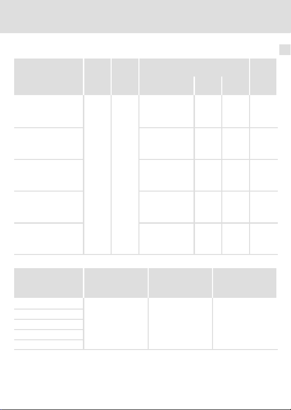
Bemessungsdaten
Spann-
Phasen max. Strom [A] Indukti-
ung
Typ [V] bei Spannung und
E82ZM75134B
E82ZM22234B020
E82ZM40234B
E82ZM75234B
E82ZM11334B
500
+10 %
3
Schaltfrequenz
500 V, 16 kHz
500 V, 8 kHz
400 V, 8 kHz
400 V, 2/4 kHz
500 V, 16 kHz
500 V, 8 kHz
400 V, 8 kHz
400 V, 2/4 kHz
500 V, 16 kHz
500 V, 8 kHz
400 V, 8 kHz
400 V, 2/4 kHz
500 V, 16 kHz
500 V, 8 kHz
400 V, 8 kHz
400 V, 2/4 kHz
500 V, 16 kHz
500 V, 8 kHz
400 V, 8 kHz
400 V, 2/4 kHz
Temperatur im Schaltschrank
max. Ausgangs-
frequenz
Typ [kHz]
E82ZM75134B
E82ZM22234B020
E82ZM40234B
E82ZM75234B
E82ZM11334B
480
Schutz der Motorwick-
lung
du/dt [V/ms]
500 < 1
Technische Daten
Bemessungsdaten
bis +40
bis +55
°C
°C
1.6
1.9
2.4
2.9
3.6
4.5
5.6
6.7
6.1
7.6
9.5
11.4
10.7
13.2
16.5
19.8
13.0
18.8
23.5
28.0
1
1.2
1.5
1.8
2.2
2.8
3.5
4.2
3.8
4.7
5.9
7.1
6.7
8.2
10.3
12.4
8.1
11.7
14.7
17.5
Begrenzung Motor-
überspannung
[kV]
vität
[mH]
4.5
1.8
1.2
0.7
0.7
2
EDK82ZM113−002 DE/EN/FR 2.1
l
15
Page 16
2 Technische Daten
Mechanische Daten
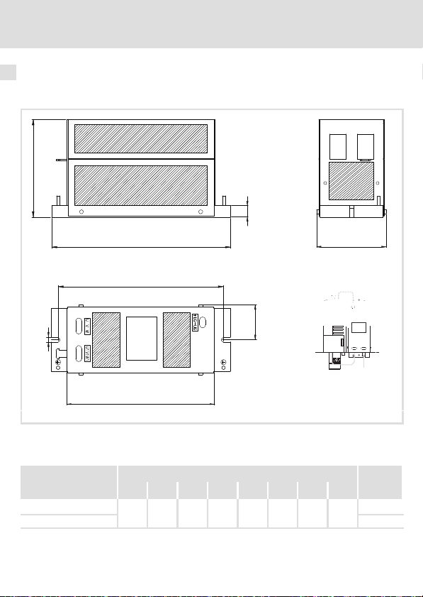
Mechanische Daten
Leistungsbereich 0.55 ... 2.2 kW
0
c
11
c1
a
d
b
b1
a1
2
b2
8200vec121
0 Schirmauflage Motorleitung
1 Anschluss PE (M5 Stehbolzen)
2 Anordnung für kurze Leitungsführung
Abmessungen [mm] Masse
Typ a a1 b b1 b2 c c1 d [kg]
E82ZM75134B
E82ZM22234B020 2.9
16
67
33.5 200 175 160 130 17 6.5
l
EDK82ZM113−002 DE/EN/FR 2.1
1.6
Page 17
Technische Daten
Mechanische Daten
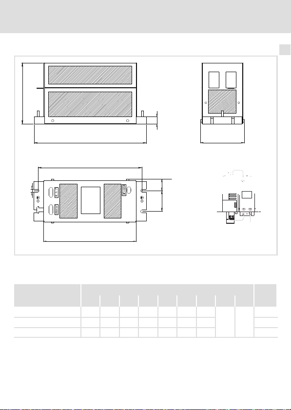
Leistungsbereich 3 ... 11 kW
0
c
11
c1
2
b
b1
d
a1a2
a
2
b2
8200vec122
0 Schirmauflage Motorleitung
1 Anschluss PE (M5 Stehbolzen)
2 Anordnung für kurze Leitungsführung
Abmessungen [mm] Masse
Typ a a1 a2 b b1 b2 c c1 d [kg]
E82ZM40234B 106 28 50 270 250 223 150
E82ZM75234B 127 26 75 300 275 257 150 6.6
E82ZM11334B 161 30.5 100 295 275 247 240 12.0
EDK82ZM113−002 DE/EN/FR 2.1
l
17 6.5
3.6
17
Page 18

3 Mechanische Installation
Wichtige Hinweise
3 Mechanische Installation
Wichtige Hinweise
ƒ Der Montageort muss den in den Technischen Daten genannten Einsatzbedingungen
immer entsprechen (^ 13). Ggf. zusätzliche Maßnahmen ergreifen.
ƒ Die Montageplatte des Schaltschranks muss folgende Eigenschaften aufweisen:
– elektrisch leitfähig
– lackfrei
ƒ Eine ungehinderte Luftzirkulation zum Abführen der Wärme muss gewährleistet
sein.
Montageschritte
So montieren Sie das Filter:
1. Geeigneten Montageort im Schaltschrank wählen.
2. Je nach Bauform, Filter mit zwei bzw. vier Schrauben und Unterlegscheiben
montieren.
18
l
EDK82ZM113−002 DE/EN/FR 2.1
Page 19

Elektrische Installation
Wichtige Hinweise
4 Elektrische Installation
Wichtige Hinweise
ƒ Die Installation muss
– den in den Technischen Daten genannten Einsatzbedingungen immer
entsprechen (^ 13).
– nach EN 60204−1 ausgeführt werden.
ƒ Bei der Auswahl des Leitungstyps beachten:
– Die verwendeten Leitungen müssen den geforderten Approbationen am
Einsatzort entsprechen (z. B. VDE, UL usw.).
– Absicherung und Leitungsquerschnitte gemäß den Vorgaben in der
Dokumentation zum Grundgerät bemessen.
ƒ Beim Verlegen der PE−Leitung beachten:
– Der PE−Anschluss muss nach EN 61800−5−1 ausgeführt werden.
4
Anschlussplan
E82xVxxxKx
U V W +UG
U
U1VV1
EDK82ZM113−002 DE/EN/FR 2.1
M
3~
PE -UG
W
PE
W1
PE
+UG
-UG
E82ZM...
l
E82ZM−014
19
Page 20

4 Elektrische Installation
Anschlussdaten
Anschlussdaten
[Nm]
[lb−in]
0.6 ... 0.8
5.3 ... 7.0
1.2 ... 2.0
10.6 ... 17.7
E82ZM75134B
E82ZM22234B020
E82ZM40234B
E82ZM75234B
E82ZM11334B
[mm2] [AWG] [mm]
0.2 ... 4
0.25 ... 4 0.25 ... 2.5 24 ... 10 8
0.2 ... 10 10
Montageschritte
So schließen Sie das Filter an:
1. Schaltschrank spannungsfrei schalten und gegen Wiedereinschalten sichern.
2. Mindestens 3 Minuten warten, dann Spannungsfreiheit des Grundgerätes prüfen.
3. Filter−Eingangsleitung und Filter−Ausgangsleitung gemäß Anschlussplan verdrahten.
– Motorleitungslänge < 100 m: geschirmt, kapazitätsarm (Schirm großflächig an der
Montageplatte auflegen)
Motorleitungslänge < 200 m: ungeschirmt
– Anzugsmoment beachten.
4. DC−Zwischenkreisleitung (+UG/−UG) gemäß Anschlussplan verdrahten.
– Die Klemmen +UG und −UG müssen mit dem gleichen Leitungsquerschnitt wie die
Motorleitung angeschlossen werden.
– Anzugsmoment beachten.
) Hinweis!
Beachten Sie bei der Inbetriebnahme, dass der Betrieb nur zulässig ist
ƒ mit einer U/f− oder U/f
ƒ mit einer Schaltfrequenz von 2 ... 16 kHz
2
−Kennliniensteuerung
20
l
EDK82ZM113−002 DE/EN/FR 2.1
Page 21

Elektrische Installation
Montageschritte
4
EDK82ZM113−002 DE/EN/FR 2.1
l
21
Page 22

0Fig. 0Tab. 0
Scope of supply
Quantity Description
1 Filter
1 Mounting Instructions
Elements on the filter
Position Description
0
1
2
3
Input terminals (U, V, W, PE)
Output terminals (U1, V1, W1, PE)
DC−bus terminals (+UG, −UG)
Nameplate
Validity information
These instructions are valid for
ƒ E82ZM75134Bmotor filters
ƒ E82ZM22234B020 motor filters
ƒ E82ZM40234B motor filters
ƒ E82ZM75234B motor filters
ƒ E82ZM11334B motor filters
22
l
EDK82ZM113−002 DE/EN/FR 2.1
Page 23

Identification
l
Typ
Fig. 1 Nameplate
E82ZM−012
EDK82ZM113−002 DE/EN/FR 2.1
l
23
Page 24

Type code
E82 Z m xxx 3 x b xxx
Product series
Accessories
Type
M = filter on the motor side
Power
e.g. 752 = 75 x 10
e.g. 113 = 11 x 103 W = 11 kW
Number of phases
3 = 3 phases
Voltage class
2 = 230 V
4 = 400/500 V
Device generation
Variant
2
W = 7.5 kW
24
l
EDK82ZM113−002 DE/EN/FR 2.1
Page 25

Application range
Motor filters are applied to reduce the motor cable load and to decrease capacitive
discharge currents to PE in long motor cables.
A motor filter is required:
ƒ in very long motor cables (regardless of the compliance with EMC limit values)
– 50 m when low−capacitance shielded (max. 100 m)
– 100 m when unshielded (max. 200 m)
Motor cables must comply with EMC limit values only with regard to conducted
interference emission.
ƒ in combination with LD RFI filters (0.25 ... 11 kW)
– for reducing the conducted noise emission when long motor cablesare used
– for compliance with EMC limit class C1 or C2
ƒ When operating motors whose insulation systems are not suitable for inverter
operation. Lenze motors have insulations with greater thermal reserves.
Please note:
ƒ Operation is only permissible if a V/f or V/f
frequency of 2 ... 16 kHz is applied.
– The filter will overheat if it is operated at another switching frequency.
ƒ The frequency inverter is loaded with an additional 12 per cent, approximately, of the
rated current of the motor filter.
ƒ The voltage drop at the motor filter averages 2−3 per cent of the max. output voltage
of the frequency inverter if the rated current of the motor filter and a frequency of 50
Hz is applied.
ƒ Overvoltages are supplied into the DC bus (+UG/−UG) via the motor filter. In this case,
the application of the motor filter in DC−bus operation is permissible.
2
characteristic control and a switching
EDK82ZM113−002 DE/EN/FR 2.1
l
25
Page 26

Assignment of filters to standard devices
Mains Type of controller P
E82xV551K4
400 V
230 V
400 V
3 ~
3 ~
3 ~
E82xV751K4 0.75
E82xV152K4 1.5
E82xV222K4 2.2
E82xV302K2 3.0
E82xV402K2 4.0
E82xV552K2 5.5
E82xV752K2 7.5
E82xV302K4 3.0
E82xV402K4 4.0
E82xV552K4 5.5
E82xV752K4 7.5
E82xV113K4 11.0 E82ZM11334B
[kW] Type of filter
r
0.55
E82ZM75134B
E82ZM22234B020
E82ZM75234B
E82ZM11334B
E82ZM40234B
E82ZM75234B
26
l
EDK82ZM113−002 DE/EN/FR 2.1
Page 27

Document history
Material number Version Description
.=7[ 2.1 07/2011 TD00 Text and address update
13282258 2.0 12/2008 TD29 New edition due to reorganisation of the
13216460 1.0 11/2007 TD29 separate reprint, EDK82ZM113−002 and
company
EDK82ZM222 replace EDK82ZM223
(00460618)
I Tip!
Information and auxiliary devices around the Lenze products can be found in
the download area at
http://www.Lenze.com
EDK82ZM113−002 DE/EN/FR 2.1
l
27
Page 28

i Contents
1 Safety instructions 29. . . . . . . . . . . . . . . . . . . . . . . . . . . . . . . . . . . . . . . . . . . . . . . . .
Notes used 29. . . . . . . . . . . . . . . . . . . . . . . . . . . . . . . . . . . . . . . . . . . . . . . . . . . . . . . .
Residual hazards 30. . . . . . . . . . . . . . . . . . . . . . . . . . . . . . . . . . . . . . . . . . . . . . . . . . .
2 Technical data 31. . . . . . . . . . . . . . . . . . . . . . . . . . . . . . . . . . . . . . . . . . . . . . . . . . . . .
General data and operating conditions 31. . . . . . . . . . . . . . . . . . . . . . . . . . . . . . .
Rated data 33. . . . . . . . . . . . . . . . . . . . . . . . . . . . . . . . . . . . . . . . . . . . . . . . . . . . . . . .
Mechanical data 34. . . . . . . . . . . . . . . . . . . . . . . . . . . . . . . . . . . . . . . . . . . . . . . . . .
3 Mechanical installation 36. . . . . . . . . . . . . . . . . . . . . . . . . . . . . . . . . . . . . . . . . . . . .
Important notes 36. . . . . . . . . . . . . . . . . . . . . . . . . . . . . . . . . . . . . . . . . . . . . . . . . . .
Mounting steps 36. . . . . . . . . . . . . . . . . . . . . . . . . . . . . . . . . . . . . . . . . . . . . . . . . . . .
4 Electrical installation 37. . . . . . . . . . . . . . . . . . . . . . . . . . . . . . . . . . . . . . . . . . . . . . .
Important notes 37. . . . . . . . . . . . . . . . . . . . . . . . . . . . . . . . . . . . . . . . . . . . . . . . . . .
Connection plan 37. . . . . . . . . . . . . . . . . . . . . . . . . . . . . . . . . . . . . . . . . . . . . . . . . . .
Connection data 38. . . . . . . . . . . . . . . . . . . . . . . . . . . . . . . . . . . . . . . . . . . . . . . . . . .
Mounting steps 38. . . . . . . . . . . . . . . . . . . . . . . . . . . . . . . . . . . . . . . . . . . . . . . . . . . .
28
l
EDK82ZM113−002 DE/EN/FR 2.1
Page 29

Safety instructions
Notes used
1 Safety instructions
Notes used
The following pictographs and signal words are used in this documentation to indicate
dangers and important information:
Safety instructions
Structure of safety instructions:
} Danger!
(characterises the type and severity of danger)
Note
(describes the danger and gives information about how to prevent dangerous
situations)
Pictograph and signal word Meaning
Danger of personal injury through dangerous electrical
voltage.
{ Danger!
} Danger!
( Stop!
Reference to an imminent danger that may result in
death or serious personal injury if the corresponding
measures are not taken.
Danger of personal injury through a general source of
danger.
Reference to an imminent danger that may result in
death or serious personal injury if the corresponding
measures are not taken.
Danger of property damage.
Reference to a possible danger that may result in
property damage if the corresponding measures are not
taken.
1
EDK82ZM113−002 DE/EN/FR 2.1
l
29
Page 30

1 Safety instructions
Residual hazards
Application notes
Pictograph and signal word Meaning
) Note!
I Tip!
,
Residual hazards
Important note to ensure troublefree operation
Useful tip for simple handling
Reference to another documentation
{ Danger!
Dangerous voltage
All power connections carry dangerous voltages both if the motor is at
standstill and after up to 3 minutes after mains switch off.
Possible consequences:
ƒ Death or severe injuries after touching the power connections.
Protective measures:
ƒ Wait for at least 3 minutes before working on the power connections.
ƒ Check whether all power connections are de−energised.
{ Danger!
Dangerous voltage
The leakage current to earth (PE) is > 3.5 mA AC or > 10 mA DC.
Possible consequences:
ƒ Death or severe injuries when the device is touched in the event of a fault.
Protective measures:
ƒ Implement the actions required in the EN 61800−5−1. Especially:
– Fixed installation
– PE connection must conform to standards (PE conductor diameter
³ 10 mm
2
or PE conductor must be connected twice)
30
l
EDK82ZM113−002 DE/EN/FR 2.1
Page 31

General data and operating conditions
Technical data
2 Technical data
General data and operating conditions
Standards
Conformity
Protection
Type of protection
Insulation resistance EN 61800−5−1 Overvoltage category III
Leakage current EN 61800−5−1 > 3.5 mA Observe regulations
Ambient conditions
Temperature
Storage −25 ... +60 °C
Transport −25 ... +70 °C
Operation −10 ... +55 °C
Site altitude 0 ... 4000 m amsl
Pollution EN 61800−5−1 Pollution degree 2
Vibration resistance EN 50178; IEC
CE Low−voltage Directive (2006/95/EC)
EN 60529
NEMA 250 Protection against contact to
61800−5−1;
Germanischer
Lloyd, general
conditions
IP 20
type 1
> 2000 m: Overvoltage category II
Current derating from +40 to +55 °C: 2.5 %/°C
1000 ... 4000 m amsl: Current derating by 5 %/1000 m
Acceleration−resistant up to 0.7 g
Not in the wire range of
the terminals
and safety instructions!
2
EDK82ZM113−002 DE/EN/FR 2.1
l
31
Page 32

2 Technical data
General data and operating conditions
Mounting conditions
Mounting location In the control cabinet
Position As close as possible to the standard device
Mounting position Vertical
Free spaces
at the top and at the
bottom
to the sides > 3 mm
Connecting cables
Standard device «
Filter
Filter « Motor
> 100 mm
As short as possible, shielded
Max. 100 m when shielded or 200 m when unshielded
32
l
EDK82ZM113−002 DE/EN/FR 2.1
Page 33

Rated data
Voltage Phases Max. current [A] Inducta
Type [V] for voltage and
E82ZM75134B
E82ZM22234B020
E82ZM40234B
E82ZM75234B
E82ZM11334B
500
+10 %
3
switching
frequency
500 V, 16 kHz
500 V, 8 kHz
400 V, 8 kHz
400 V, 2/4 kHz
500 V, 16 kHz
500 V, 8 kHz
400 V, 8 kHz
400 V, 2/4 kHz
500 V, 16 kHz
500 V, 8 kHz
400 V, 8 kHz
400 V, 2/4 kHz
500 V, 16 kHz
500 V, 8 kHz
400 V, 8 kHz
400 V, 2/4 kHz
500 V, 16 kHz
500 V, 8 kHz
400 V, 8 kHz
400 V, 2/4 kHz
Temperature in the control cabinet
Max. output frequency Protection of the
Type [kHz]
E82ZM75134B
E82ZM22234B020
E82ZM40234B
E82ZM75234B
E82ZM11334B
480
motor winding
du/dt [V/ms]
Technical data
Rated data
up to
up to
+40 °C
+55 °C
1.6
1.9
2.4
2.9
3.6
4.5
5.6
6.7
6.1
7.6
9.5
11.4
10.7
13.2
16.5
19.8
13.0
18.8
23.5
28.0
500 < 1
1
1.2
1.5
1.8
2.2
2.8
3.5
4.2
3.8
4.7
5.9
7.1
6.7
8.2
10.3
12.4
8.1
11.7
14.7
17.5
Limitation of the
motor overvoltage
[kV]
2
nce
[mH]
4.5
1.8
1.2
0.7
0.7
EDK82ZM113−002 DE/EN/FR 2.1
l
33
Page 34

2 Technical data
Mechanical data
Mechanical data
Power range from 0.55 ... 2.2 kW
0
c
11
c1
a
d
b
b1
a1
2
b2
8200vec121
0 Shield connection for motor cable
1 PE connection (M5 stud)
2 Arrangement for short cables
Dimensions [mm] Mass
Type a a1 b b1 b2 c c1 d [kg]
E82ZM75134B
E82ZM22234B020 2.9
34
67
33.5 200 175 160 130 17 6.5
l
EDK82ZM113−002 DE/EN/FR 2.1
1.6
Page 35

Technical data
Mechanical data
Power range from 3 ... 11 kW
0
c
11
c1
2
b
b1
d
a1a2
a
2
b2
8200vec122
0 Shield connection for motor cable
1 PE connection (M5 stud)
2 Arrangement for short cables
Dimensions [mm] Mass
Type a a1 a2 b b1 b2 c c1 d [kg]
E82ZM40234B 106 28 50 270 250 223 150
E82ZM75234B 127 26 75 300 275 257 150 6.6
E82ZM11334B 161 30.5 100 295 275 247 240 12.0
EDK82ZM113−002 DE/EN/FR 2.1
l
17 6.5
3.6
35
Page 36

3 Mechanical installation
Important notes
3 Mechanical installation
Important notes
ƒ The mounting location must always comply with the operating conditions specified
in the technical data (^ 31). Take additional measures if necessary.
ƒ The mounting plate of the control cabinet must have the following properties:
– electrically conductive
– free of lacquer
ƒ A free air circulation must be ensured for dissipating the heat.
Mounting steps
How to mount the filter:
1. Select a suitable mounting location in the control cabinet.
2. Depending on the design, mount the filter using two or four screws and washers.
36
l
EDK82ZM113−002 DE/EN/FR 2.1
Page 37

Electrical installation
Important notes
4 Electrical installation
Important notes
ƒ Installation must
– always be in accordance with the operating conditions specified in the Technical
data (^ 31).
– be carried out to EN 60204−1.
ƒ Please observe the following when selecting the cable type:
– The cables used must comply with the approvals required for the application (e. g.
VDE, UL etc.).
– Fuses and cable cross−sections must be dimensioned in accordance with the
specifications in the documentation for the basic device.
ƒ Please observe the following when laying the PE cable:
– The PE connection must comply with EN 61800−5−1.
4
Connection plan
E82xVxxxKx
U V W +UG
U
U1VV1
EDK82ZM113−002 DE/EN/FR 2.1
M
3~
PE -UG
W
PE
W1
PE
+UG
-UG
E82ZM...
l
E82ZM−014
37
Page 38

4 Electrical installation
Connection data
Connection data
[Nm]
[lb−in]
0.6 ... 0.8
5.3 ... 7.0
1.2 ... 2.0
10.6 ... 17.7
E82ZM75134B
E82ZM22234B020
E82ZM40234B
E82ZM75234B
E82ZM11334B
[mm2] [AWG] [mm]
0.2 ... 4
0.25 ... 4 0.25 ... 2.5 24 ... 10 8
0.2 ... 10 10
Mounting steps
How to connect the filter:
1. De−energise the control cabinet and fuse it against re−energisation.
2. Wait for at least 3 minutes before checking the standard device for isolation from
supply.
3. Wire the filter input cables and the filter output cables according to the connection
plan.
– Motor cable length < 100 m: shielded, low−capacitance (connect the shield with a
surface as large as possible on the mounting plate)
Motor cable length < 200 m: unshielded
– Observe tightening torque.
4. Wire the DC−bus cables (+UG/−UG) according to the connection plan.
– The terminals +UG und −UG must be connected using the same cable cross−section
as in the motor cable.
– Observe tightening torque.
) Note!
When commissioning, please observe that operation is only permissible
ƒ with V/f or V/f
ƒ at a switching frequency of 2 ... 16 kHz
2
characteristic control
38
l
EDK82ZM113−002 DE/EN/FR 2.1
Page 39

Electrical installation
Mounting steps
4
EDK82ZM113−002 DE/EN/FR 2.1
l
39
Page 40

0Fig. 0Tab. 0
Equipement livré
Nombre Description
1 Filtre
1 Instructions de montage
Eléments du filtre
Position Description
0
1
2
3
Bornes d’entrée (U, V, W, PE)
Bornes de sortie (U1, V1, W1, PE)
Bornier de raccordement bus CC (+UG, −UG)
Plaque signalétique
Validité
Le présent document s’applique au produit suivant :
ƒ Filtre moteur E82ZM75134B
ƒ Filtre moteur E82ZM22234B020
ƒ Filtre moteur E82ZM40234B
ƒ Filtre moteur E82ZM75234B
ƒ Filtre moteur E82ZM11334B
40
l
EDK82ZM113−002 DE/EN/FR 2.1
Page 41

Identification
l
Typ
Fig. 1 Plaque signalétique
E82ZM−012
EDK82ZM113−002 DE/EN/FR 2.1
l
41
Page 42

Codification des types
Série
d’appareils
Accessoires
Type
M = filtre côté moteur
E82 Z m xxx 3 x b xxx
Puissance
p. ex. 752 = 75 x 10
p. ex. 113 = 11 x 103 W = 11 kW
Nombre de phases
3 = 3 phases
Classe de tension
2 = 230 V
4 = 400/500 V
Génération d’appareils
Variante
2
W = 7,5 kW
42
l
EDK82ZM113−002 DE/EN/FR 2.1
Page 43

Utilisation
Les filtres moteur sont utilisés pour réduire la charge dans le bobinage moteur, ainsi que les
courants de fuite capacitifs sur PE en cas de câbles moteur longs.
Le recours à un filtre moteur est impératif :
ƒ en cas de câble moteur très long (indépendamment du respect des valeurs limites de
CEM)
– 50 m : câble blindé de faible capacité (100 m max.)
– 100 m : câble non blindé (200 m max.)
Les câbles moteur doivent respecter les valeurs limites prescrites en matière de CEM
uniquement en matière de perturbations radioélectriques transmises par câble.
ƒ en combinaison avec un filtre antiparasite LD (0,25 ... 11 kW) :
– pour réduire les perturbations radioélectriques transmises par câble (câble moteur
long) ;
– pour respecter les exigences de la classe CEM C1 ou C2.
ƒ en cas d’utilisation de moteurs dotés de systèmes d’isolement inadaptés à un
fonctionnement avec variateur. Sur les moteurs Lenze, les systèmes d’isolement
disposent d’une réserve thermique importante.
Noter les points suivants :
ƒ Le fonctionnement est autorisé uniquement avec une commande en U/f ou U/f
avec une fréquence de découpage comprise entre 2 et 16 kHz.
– Le filtre atteint une température trop élevée avec les autres fréquences de
découpage.
ƒ La charge supplémentaire du convertisseur de fréquence correspond à environ 12%
du courant nominal du filtre moteur.
ƒ La chute de tension au niveau du filtre moteur au courant nominal et à une
fréquence de 50 Hz correspond à 2−3% de la tension de sortie max. du convertisseur
de fréquence.
ƒ Des surtensions sont induites par le filtre moteur dans le bus CC (+UG/−UG).
L’utlisation du filtre moteur est autorisée pour un fonctionnement en
interconnexion.
2
et
EDK82ZM113−002 DE/EN/FR 2.1
l
43
Page 44

Combinaisons filtre ˘ appareil de base
Réseau Type d’appareil P
E82xV551K4
400 V
230 V
400 V
3 ~
3 ~
3 ~
E82xV751K4 0.75
E82xV152K4 1.5
E82xV222K4 2.2
E82xV302K2 3.0
E82xV402K2 4.0
E82xV552K2 5.5
E82xV752K2 7.5
E82xV302K4 3.0
E82xV402K4 4.0
E82xV552K4 5.5
E82xV752K4 7.5
E82xV113K4 11.0 E82ZM11334B
[kW] Type de filtre
N
0.55
E82ZM75134B
E82ZM22234B020
E82ZM75234B
E82ZM11334B
E82ZM40234B
E82ZM75234B
44
l
EDK82ZM113−002 DE/EN/FR 2.1
Page 45

Historique du document
Numéro de document Version Description
.=7[ 2.1 07/2011 TD00 Textes et adresse mis à jour
13282258 2.0 12/2008 TD29 Nouvelle édition en raison de la nouvelle
13216460 1.0 11/2007 TD29 Réédition segmentée, EDK82ZM113−002 et
organisation de l’entreprise
EDK82ZM222 remplacent EDK82ZM223
(00460618)
I Conseil !
Toutes les informations relatives aux produits Lenze peuvent être téléchargées
sur notre site à l’adresse suivante :
http://www.Lenze.com
EDK82ZM113−002 DE/EN/FR 2.1
l
45
Page 46

i Sommaire
1 Consignes de sécurité 47. . . . . . . . . . . . . . . . . . . . . . . . . . . . . . . . . . . . . . . . . . . . . . .
Consignes utilisées 47. . . . . . . . . . . . . . . . . . . . . . . . . . . . . . . . . . . . . . . . . . . . . . . . .
Dangers résiduels 49. . . . . . . . . . . . . . . . . . . . . . . . . . . . . . . . . . . . . . . . . . . . . . . . . .
2 Spécifications techniques 50. . . . . . . . . . . . . . . . . . . . . . . . . . . . . . . . . . . . . . . . . . .
Caractéristiques générales et conditions d’utilisation 50. . . . . . . . . . . . . . . . . . . .
Caractéristiques assignées 52. . . . . . . . . . . . . . . . . . . . . . . . . . . . . . . . . . . . . . . . . . .
Caractéristiques mécaniques 53. . . . . . . . . . . . . . . . . . . . . . . . . . . . . . . . . . . . . . . .
3 Installation mécanique 55. . . . . . . . . . . . . . . . . . . . . . . . . . . . . . . . . . . . . . . . . . . . . .
Remarques importantes 55. . . . . . . . . . . . . . . . . . . . . . . . . . . . . . . . . . . . . . . . . . . . .
Opérations de montage 55. . . . . . . . . . . . . . . . . . . . . . . . . . . . . . . . . . . . . . . . . . . . .
4 Installation électrique 56. . . . . . . . . . . . . . . . . . . . . . . . . . . . . . . . . . . . . . . . . . . . . . .
Remarques importantes 56. . . . . . . . . . . . . . . . . . . . . . . . . . . . . . . . . . . . . . . . . . . . .
Schéma de câblage 56. . . . . . . . . . . . . . . . . . . . . . . . . . . . . . . . . . . . . . . . . . . . . . . . .
Données de raccordement 57. . . . . . . . . . . . . . . . . . . . . . . . . . . . . . . . . . . . . . . . . . .
Opérations de montage 57. . . . . . . . . . . . . . . . . . . . . . . . . . . . . . . . . . . . . . . . . . . . .
46
l
EDK82ZM113−002 DE/EN/FR 2.1
Page 47

Consignes de sécurité
Consignes utilisées
1 Consignes de sécurité
Consignes utilisées
Pour indiquer des risques et des informations importantes, la présente documentation
utilise les mots et symboles suivants :
Consignes de sécurité
Présentation des consignes de sécurité
} Danger !
(Le pictogramme indique le type de risque.)
Explication
(L’explication décrit le risque et les moyens de l’éviter.)
Pictogramme et mot associé Explication
Situation dangereuse pour les personnes en raison d’une
tension électrique élevée
{ Danger !
} Danger !
( Stop !
Indication d’un danger imminent qui peut avoir pour
conséquences des blessures mortelles ou très graves en
cas de non−respect des consignes de sécurité
correspondantes
Situation dangereuse pour les personnes en raison d’un
danger d’ordre général
Indication d’un danger imminent qui peut avoir pour
conséquences des blessures mortelles ou très graves en
cas de non−respect des consignes de sécurité
correspondantes
Risques de dégâts matériels
Indication d’un risque potentiel qui peut avoir pour
conséquences des dégâts matériels en cas de non−respect
des consignes de sécurité correspondantes
1
EDK82ZM113−002 DE/EN/FR 2.1
l
47
Page 48

1 Consignes de sécurité
Consignes utilisées
Consignes d’utilisation
Pictogramme et mot associé Explication
) Remarque
importante !
I Conseil !
,
Remarque importante pour assurer un fonctionnement
correct
Conseil utile pour faciliter la mise en uvre
Référence à une autre documentation
48
l
EDK82ZM113−002 DE/EN/FR 2.1
Page 49

Consignes de sécurité
Dangers résiduels
Dangers résiduels
{ Danger !
Tension électrique dangereuse
Une tension électrique dangereuse circule dans tous les raccordements de
puissance, même à l’arrêt et jusqu’à 3 minutes après une coupure réseau.
Risques encourus :
ƒ Mort ou blessures graves en cas de contact accidentel avec les
raccordements de puissance.
Mesures de protection :
ƒ Attendre au moins 3 minutes avant toute intervention sur les
raccordements de puissance.
ƒ S’assurer que tous les raccordements de puissance sont hors tension.
{ Danger !
Tension électrique dangereuse
Le courant de fuite vers la terre (PE) est > 3.5 mA CA ou > 10 mA CC.
Risques encourus
ƒ Mort ou blessures graves en cas de contact accidentel avec l’appareil en
défaut
Mesures de protection
ƒ Appliquer les dispositions prescrites par la norme EN 61800−5−1. Assurer,
en particulier,
– une installation fixe,
– le raccordement PE conformément à la norme (section de câble PE
³ 10 mm2 ou double raccordement du câble PE).
1
EDK82ZM113−002 DE/EN/FR 2.1
l
49
Page 50

2 Spécifications techniques
Caractéristiques générales et conditions d’utilisation
2 Spécifications techniques
Caractéristiques générales et conditions d’utilisation
Normes
Conformité
Protection
Indice de protection
Résistance d’isolement EN 61800−5−1 Catégorie de surtension III
Courant de fuite EN 61800−5−1 > 3.5 mA Tenir compte des
Conditions climatiques
Température
Stockage −25 ... +60 °C
Transport −25 ... +70 °C
Fonctionnement −10 ... +55 °C
Altitude d’implantation 0 ... 4000 m au−dessus du niveau de la mer
Pollution ambiante
admissible
Résistance aux chocs EN50178 ;
CE Directive Basse Tension (2006/95/CE)
EN 60529
NEMA 250 Protection contre contacts
EN 61800−5−1 Degré de pollution 2
IEC61800−5−1 ;
Germanischer
Loyd, Conditions
générales
IP 20
accidentels selon type 1
Réduction à partir de 2000 m : catégorie de
surtension II
Réduction de courant entre +40 et +55 °C : 2,5 %/°C
1000 ... 4000 m au−dessus du niveau de la mer :
réduction de courant de 5 %/1000 m
Résistance à l’accélération jusqu’à 0,7 g
Pas dans la zone de
raccordement des
bornes
prescriptions et des
consignes de sécurité !
50
l
EDK82ZM113−002 DE/EN/FR 2.1
Page 51

Caractéristiques générales et conditions d’utilisation
Spécifications techniques
Conditions de montage
Lieu de montage Armoire électrique
Position de montage Le plus près possible de l’appareil de base
Orientation de
montage
Espaces de montage
En haut et en bas > 100 mm
Sur le côté > 3 mm
Câbles de
raccordement
Appareil de base «
Filtre
Filtre « Moteur
Verticale
Le plus court possible, blindé
100 m max. avec blindage ou 200 m sans blindage
2
EDK82ZM113−002 DE/EN/FR 2.1
l
51
Page 52

2 Spécifications techniques
Caractéristiques assignées
Caractéristiques assignées
Tension Phases Courant max. [A] Inducta
Type [V] Tension et
E82ZM75134B
E82ZM22234B020
E82ZM40234B
500
+10 %
E82ZM75234B
E82ZM11334B
Température dans l’armoire électrique
Fréquence de sortie
max.
Type [kHz]
E82ZM75134B
E82ZM22234B020
E82ZM40234B
E82ZM75234B
E82ZM11334B
480
3
fréquence de
découpage
500 V, 16 kHz
500 V, 8 kHz
400 V, 8 kHz
400 V, 2/4 kHz
500 V, 16 kHz
500 V, 8 kHz
400 V, 8 kHz
400 V, 2/4 kHz
500 V, 16 kHz
500 V, 8 kHz
400 V, 8 kHz
400 V, 2/4 kHz
500 V, 16 kHz
500 V, 8 kHz
400 V, 8 kHz
400 V, 2/4 kHz
500 V, 16 kHz
500 V, 8 kHz
400 V, 8 kHz
400 V, 2/4 kHz
bobinage moteur
Jusqu’à
+40 °C
1,6
1,9
2,4
2,9
3,6
4,5
5,6
6,7
6,1
7,6
9,5
11,4
10,7
13,2
16,5
19,8
13,0
18,8
23,5
28,0
Protection du
du/dt [V/ms]
500 < 1
nce
Jusqu’à
+55 °C
Limitation de la
surtension du moteur
1,2
1,5
1,8
2,2
2,8
3,5
4,2
3,8
4,7
5,9
7,1
6,7
8,2
10,3
12,4
8,1
11,7
14,7
17,5
[mH]
1
4,5
1,8
1,2
0,7
0,7
[kV]
52
l
EDK82ZM113−002 DE/EN/FR 2.1
Page 53

Caractéristiques mécaniques
Plage de puissance : 0.55 ... 2.2 kW
0
c
Spécifications techniques
Caractéristiques mécaniques
11
c1
2
b
b1
a1
d
a
2
b2
8200vec121
0 Reprise du blindage câble moteur
1 Raccordement PE (boulon fileté M5)
2 Disposition pour conduite de câble courte
Cotes [mm] Poids
Type a a1 b b1 b2 c c1 d [kg]
E82ZM75134B
E82ZM22234B020 2.9
EDK82ZM113−002 DE/EN/FR 2.1
67
33.5 200 175 160 130 17 6.5
l
1.6
53
Page 54

2 Spécifications techniques
Caractéristiques mécaniques
Plage de puissance 3 ... 11 kW
0
c
11
c1
a
d
b
b1
a1a2
2
b2
8200vec122
0 Reprise du blindage câble moteur
1 Raccordement PE (boulon fileté M5)
2 Disposition pour conduite de câble courte
Cotes [mm] Poids
Type a a1 a2 b b1 b2 c c1 d [kg]
E82ZM40234B 106 28 50 270 250 223 150
E82ZM75234B 127 26 75 300 275 257 150 6.6
E82ZM11334B 161 30.5 100 295 275 247 240 12.0
54
l
17 6.5
EDK82ZM113−002 DE/EN/FR 2.1
3.6
Page 55

Installation mécanique
Remarques importantes
3 Installation mécanique
Remarques importantes
ƒ L’emplacement de montage doit impérativement remplir les conditions d’utilisation
décrites dans les spécifications techniques.(^ 50). Si nécessaire, prendre des mesures
complémentaires.
ƒ La plaque de montage de l’armoire électrique doit présenter les caractéristiques
suivantes :
– Conductivité électrique
– Pas de vernis
ƒ Veiller à assurer une bonne circulation de l’air en vue de la dissipation de la chaleur.
Opérations de montage
Pour monter le filtre :
1. Choisir un emplacement adapté dans l’armoire électrique.
2. Suivant la forme de construction, monter le filtre avec 2 ou 4 vis et rondelles plates.
3
EDK82ZM113−002 DE/EN/FR 2.1
l
55
Page 56

4 Installation électrique
Remarques importantes
4 Installation électrique
Remarques importantes
ƒ L’installation doit
– toujours respecter les conditions d’utilisation indiquées dans les spécifications
techniques (^ 50) ;
– répondre aux exigences de la norme EN 60204−1.
ƒ Lors du choix du type de câble, tenir compte des points suivants :
– Les câbles utilisés doivent être conformes aux homologations requises sur le lieu
d’utilisation (exemples : VDE, UL, etc.).
– Les fusibles et les sections de câble doivent être dimensionnés conformément aux
prescriptions figurant dans la documentation de l’appareil de base.
ƒ Lors de la pose du câble PE, tenir compte du point suivant :
– Le raccordement PE doit être effectué conformément à la norme EN 61800−5−1.
Schéma de câblage
E82xVxxxKx
U V W +UG
U
U1VV1
M
3~
PE -UG
W
PE
W1
PE
+UG
-UG
E82ZM...
56
l
E82ZM−014
EDK82ZM113−002 DE/EN/FR 2.1
Page 57

Données de raccordement
Installation électrique
Données de raccordement
4
[Nm]
[lb−in]
0.6 ... 0.8
5.3 ... 7.0
1.2 ... 2.0
10.6 ... 17.7
E82ZM75134B
E82ZM22234B020
E82ZM40234B
E82ZM75234B
E82ZM11334B
[mm2] [AWG] [mm]
0.2 ... 4
0.25 ... 4 0.25 ... 2.5 24 ... 10 8
0.2 ... 10 10
Opérations de montage
Pour raccorder le filtre, procéder comme suit :
1. Couper la tension dans l’armoire électrique et s’assurer que toute mise sous tension
est exclue.
2. Attendre au moins 3 minutes puis s’assurer que l’appareil de base est hors tension.
3. Raccorder les câbles d’entrée et de sortie du filtre conformément au plan de
raccordement.
– Longueur de câble moteur < 100 m : avec blindage, câble de faible capacité (poser
le blindage en appliquant une surface de contact importante avec la plaque de
montage)
Longueur de câble moteur < 200 m : sans blindage
– Respecter le couple de serrage.
4. Brancher le câble du bus CC (+UG/−UG) conformément au plan de raccordement.
– Les bornes +UG et −UG doivent être reliées à la même section de câble que le câble
moteur.
– Respecter le couple de serrage.
) Remarque importante !
Lors de la mise en service, garder à l’esprit que le fonctionnement est autorisé
uniquement
ƒ avec une commande en U/f ou U/f
ƒ avec une fréquence de découpage comprise entre 2 et 16 kHz.
2
;
EDK82ZM113−002 DE/EN/FR 2.1
l
57
Page 58

© 07/2011
Lenze Automation GmbH
F
Hans−Lenze−Str. 1
D−31855 Aerzen
Germany
(
+49(0)51 54 /82−0
Ê
+49(0)51 54 /82 − 28 00
Lenze@Lenze.de
ü
www.Lenze.com
Q
Service Lenze Service GmbH
Breslauer Straße 3
D−32699 Extertal
Germany
(
008000/ 2446877 (24 h helpline)
Ê
+49(0)5154/ 82−11 12
Service@Lenze.de
EDK82ZM113−002 § .=7[ § DE/EN/FR § 2.1 § TD00
10987654321
 Loading...