

Page 1
EDK82ZM113−001
.6aZ
Ä.6aZä
Global Drive
Montageanleitung
Mounting Instructions
Instructions de montage
8200 vector
E82ZMxxxxxBxxx
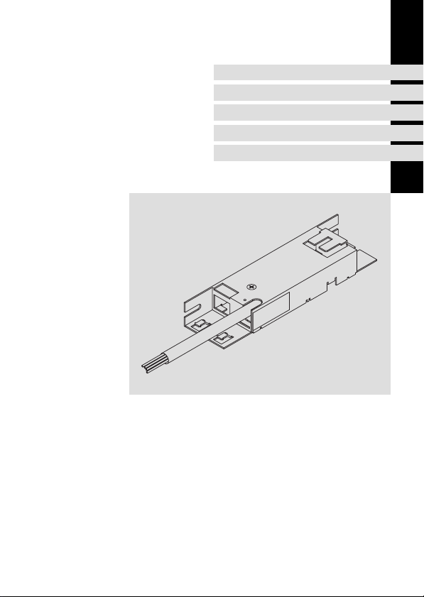
Motor−Entstörmodul
Motor interference suppression module
Module d’antiparasitage moteur
l
Page 2

, Lesen Sie zuerst diese Anleitung und die Dokumentation zum Grundgerät,
bevor Sie mit den Arbeiten beginnen!
Beachten Sie die enthaltenen Sicherheitshinweise.
, Please read these instructions and the documentation of the standard
device before you start working!
Observe the safety instructions given therein!
, Lire le présent fascicule et la documentation relative à l’appareil de base
avant toute manipulation de l’équipement !
Respecter les consignes de sécurité fournies.
Page 3
5
0
4
1
3
2
E82ZM−001
Page 4

0Abb. 0Tab. 0
Lieferumfang
Anzahl Beschreibung
1 Filter
1 Montageanleitung
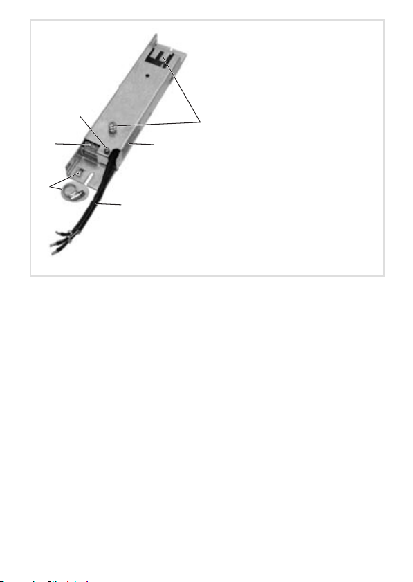
Elemente am Filter
Position Beschreibung
0
1
2
3
4
5
Informationen zur Gültigkeit
Diese Anleitung ist gültig für
ƒ Motor−Entstörmodul E82ZM37132B002
ƒ Motor−Entstörmodul E82ZM75134B004
ƒ Motor−Entstörmodul E82ZM11334B004
ƒ Motor−Entstörmodul E82ZM22234B004
ƒ Motor−Entstörmodul E82ZM75134B005
ƒ Motor−Entstörmodul E82ZM22234B005
ƒ Motor−Entstörmodul E82ZM11334B005
Montagepunkte Grundgerät bei Unterbau−Montage (Standard)
Typenschild
Anschlussleitung Eingang (U, V, W, PE)
Schirmauflage, Schirmschelle
Anschlussklemmen Motorleitung (U1, V1, W1)
PE−Anschlussschraube Motorleitung
4
l
EDK82ZM113−001 DE/EN/FR 1.1
Page 5
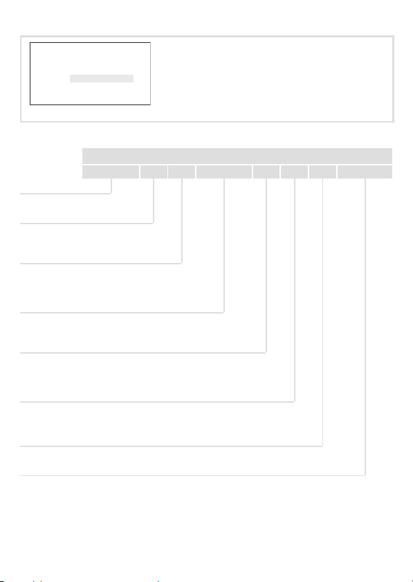
Identifikation
L
xxxxxxxxxxxxxxxx
Art.-Nr. / Part No.:
Typ / Type:
xxxxxxxxxxxxxxxxxxxxxx
xxxxxxxxxxxxxxxxxxxxxxxxxxxxxxxxxxxxxxxx
Abb. 1 Typenschild
xxxxxx
E82ZZ37112B200
E82ZZ005
Typenschlüssel
E82 Z M xxx 3 x B xxx
Produktreihe
Zubehör
Typ
M = motorseitiger Filter
Leistung
z. B. 752 = 75 x 10
z. B. 113 = 11 x 103 W = 11 kW
Anzahl Phasen
3 = 3 Phasen
Spannungsklasse
2 = 230 V
4 = 400/500 V
Gerätegeneration
Variante
2
W = 7,5 kW
EDK82ZM113−001 DE/EN/FR 1.1
l
5
Page 6

Einsetzbarkeit
Ein Motor−Entstörmodul setzen Sie ein, um Störströme in der Motorleitung zu reduzieren.
Zuordnung Filter ˘ Grundgerät
Filter−Typ
8200 vector 9300 vector 9300 Servo
E82ZM37132B002 E82xV251K2
E82ZM75134B004 E82xV551Kx
E82ZM11334B004 E82xV302Kx
E82ZM75134B005 E82xV551K4
E82ZM22234B004 E82xV152Kx
E82ZM22234B005 E82xV152K4
E82ZM11334B005 E82xV302K4
E82xV371K2
E82xV751Kx
E82xV402Kx
E82xV552Kx
E82xV752Kx
E82xV113K4
E82xV751K4
E82xV222Kx
E82xV222K4
E82xV402K4
E82xV552K4
E82xV752K4
E82xV113K4
Antriebsregler−Typ
− −
− −
− −
− −
− −
− −
− −
6
l
EDK82ZM113−001 DE/EN/FR 1.1
Page 7

Dokumenthistorie
Materialnummer Version Beschreibung
.6aZ 1.1 07/2010 TD29 Umfirmierung
13216457 1.0 11/2007 TD29 Abgespaltene Neuauflage,
ersetzt EDK82ZM113
(00453091)
I Tipp!
Dokumentationen und Software−Updates zu weiteren Lenze Produkten finden
Sie im Internet im Bereich "Services & Downloads" unter
http://www.Lenze.com
EDK82ZM113−001 DE/EN/FR 1.1
l
7
Page 8

i Inhalt
1 Sicherheitshinweise 9 . . . . . . . . . . . . . . . . . . . . . . . . . . . . . . . . . . . . . . . . . . . . . . . .
Verwendete Hinweise 9 . . . . . . . . . . . . . . . . . . . . . . . . . . . . . . . . . . . . . . . . . . . . . . .
Restgefahren 10 . . . . . . . . . . . . . . . . . . . . . . . . . . . . . . . . . . . . . . . . . . . . . . . . . . . . . .
2 Technische Daten 11 . . . . . . . . . . . . . . . . . . . . . . . . . . . . . . . . . . . . . . . . . . . . . . . . . .
Allgemeine Daten und Einsatzbedingungen 11 . . . . . . . . . . . . . . . . . . . . . . . . . . .
Bemessungsdaten 13 . . . . . . . . . . . . . . . . . . . . . . . . . . . . . . . . . . . . . . . . . . . . . . . . . .
Mechanische Daten 14 . . . . . . . . . . . . . . . . . . . . . . . . . . . . . . . . . . . . . . . . . . . . . . .
3 Mechanische Installation 15 . . . . . . . . . . . . . . . . . . . . . . . . . . . . . . . . . . . . . . . . . . . .
Wichtige Hinweise 15 . . . . . . . . . . . . . . . . . . . . . . . . . . . . . . . . . . . . . . . . . . . . . . . . .
Montageschritte 16 . . . . . . . . . . . . . . . . . . . . . . . . . . . . . . . . . . . . . . . . . . . . . . . . . . .
4 Elektrische Installation 19 . . . . . . . . . . . . . . . . . . . . . . . . . . . . . . . . . . . . . . . . . . . . . .
Wichtige Hinweise 19 . . . . . . . . . . . . . . . . . . . . . . . . . . . . . . . . . . . . . . . . . . . . . . . . .
Anschlussplan 20 . . . . . . . . . . . . . . . . . . . . . . . . . . . . . . . . . . . . . . . . . . . . . . . . . . . . .
Anschlussdaten 20 . . . . . . . . . . . . . . . . . . . . . . . . . . . . . . . . . . . . . . . . . . . . . . . . . . . .
Montageschritte 21 . . . . . . . . . . . . . . . . . . . . . . . . . . . . . . . . . . . . . . . . . . . . . . . . . . .
8
l
EDK82ZM113−001 DE/EN/FR 1.1
Page 9
Sicherheitshinweise
Verwendete Hinweise
1 Sicherheitshinweise
Verwendete Hinweise
Um auf Gefahren und wichtige Informationen hinzuweisen, werden in dieser Dokumentation folgende Piktogramme und Signalwörter verwendet:
Sicherheitshinweise
Aufbau der Sicherheitshinweise:
} Gefahr!
(kennzeichnet die Art und die Schwere der Gefahr)
Hinweistext
(beschreibt die Gefahr und gibt Hinweise, wie sie vermieden werden kann)
Piktogramm und Signalwort Bedeutung
Gefahr von Personenschäden durch gefährliche elektrische Spannung
{ Gefahr!
} Gefahr!
( Stop!
Hinweis auf eine unmittelbar drohende Gefahr, die den
Tod oder schwere Verletzungen zur Folge haben kann,
wenn nicht die entsprechenden Maßnahmen getroffen
werden.
Gefahr von Personenschäden durch eine allgemeine Gefahrenquelle
Hinweis auf eine unmittelbar drohende Gefahr, die den
Tod oder schwere Verletzungen zur Folge haben kann,
wenn nicht die entsprechenden Maßnahmen getroffen
werden.
Gefahr von Sachschäden
Hinweis auf eine mögliche Gefahr, die Sachschäden zur
Folge haben kann, wenn nicht die entsprechenden Maßnahmen getroffen werden.
1
EDK82ZM113−001 DE/EN/FR 1.1
l
9
Page 10

1 Sicherheitshinweise
Restgefahren
Anwendungshinweise
Piktogramm und Signalwort Bedeutung
) Hinweis!
I Tipp!
,
Restgefahren
Wichtiger Hinweis für die störungsfreie Funktion
Nützlicher Tipp für die einfache Handhabung
Verweis auf andere Dokumentation
{ Gefahr!
Gefährliche elektrische Spannung
Alle Leistungsanschlüsse führen sowohl bei gestopptem Motor als auch bis zu
3 Minuten nach Netz−Ausschalten gefährliche elektrische Spannung.
Mögliche Folgen:
ƒ Tod oder schwere Verletzungen beim Berühren der Leistungsanschlüsse.
Schutzmaßnahmen:
ƒ Vor Arbeiten an den Leistungsanschlüssen mindestens 3 Minuten warten.
ƒ Prüfen, ob alle Leistungsanschlüsse spannungsfrei sind.
{ Gefahr!
Gefährliche elektrische Spannung
Der Ableitstrom gegen Erde (PE) ist > 3.5 mA AC bzw. > 10 mA DC.
Mögliche Folgen:
ƒ Tod oder schwere Verletzungen beim Berühren des Gerätes im Fehlerfall.
Schutzmaßnahmen:
ƒ Die in der EN 61800−5−1 geforderten Maßnahmen umsetzen.
Insbesondere:
– Festinstallation
– PE−Anschluss normgerecht ausführen (PE−Leiterdurchmesser ³ 10 mm
oder PE−Leiter doppelt auflegen)
2
10
l
EDK82ZM113−001 DE/EN/FR 1.1
Page 11
Allgemeine Daten und Einsatzbedingungen
Technische Daten
2 Technische Daten
Allgemeine Daten und Einsatzbedingungen
Schutz
Schutzart
Isolationsfestigkeit EN 61800−5−1 Überspannungskategorie III
Ableitstrom EN 61800−5−1 > 3.5 mA Bestimmungen und
Umweltbedingungen
Temperatur
Lagerung
Transport −25 ... +70 °C
Betrieb −10 ... +55 °C
Aufstellhöhe 0 ... 4000 m üNN
Verschmutzung EN 61800−5−1 Verschmutzungsgrad 2
Rüttelfestigkeit EN50178;
EN 60529
NEMA 250 Berührschutz nach Typ 1
IEC61800−5−1;
Germanischer
Loyd, allgemeine
Bedingungen
IP 20
Reduzierung ab 2000 m: Überspannungskategorie II
−25 ... +60 °C
Stromreduzierung von +40 ... +55 °C: 2.5 %/°C
1000 ... 4000 m üNN: Stromreduzierung 5 %/1000 m
Beschleunigungsfest bis 0.7 g
nicht im Anschlussbereich der Klemmen
Sicherheitshinweise
beachten!
2
EDK82ZM113−001 DE/EN/FR 1.1
l
11
Page 12
2 Technische Daten
Allgemeine Daten und Einsatzbedingungen
Montagebedingungen
Montageort im Schaltschrank
Montageposition Standard: zwischen Montageplatte und Grundgerät
Einbaulage senkrecht
Einbaufreiräume
oben > 90 mm
unten > 100 mm
seitlich > 3 mm
Anschlussleitungen
Filter « Motor
1) Für Motorleitungen gilt die Einhaltung der EMV−Grenzwerte nur für die leitungsgebundene
Störaussendung.
2) Max. Motorleitungslänge bei Schaltfrequenz 16 kHz:
E82ZM22234B004, E82ZM75134B004, E82ZM11334B004 = 10 m
E82ZM75134B005, E82ZM22234B005 und E82ZM11334B005 = 25 m
Variante: rechts neben dem Grundgerät
max. 50 m geschirmt, kapazitätsarm oder max. 100 m ungeschirmt 1)
2)
12
l
EDK82ZM113−001 DE/EN/FR 1.1
Page 13
Technische Daten
Bemessungsdaten
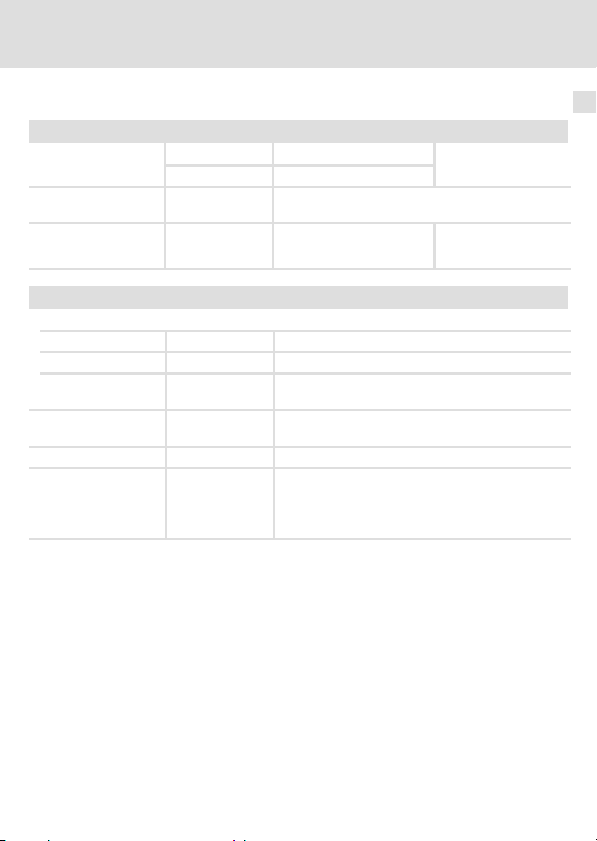
Bemessungsdaten
Spannung Fre-
Typ [V] [Hz]
E82ZM37132B002 240 0 ... 650 2.4 1.5 12
E82ZM75134B004
E82ZM22234B004 9.5/6.7 5.9/4.2 20
E82ZM11334B004 28.6/23.5 17.9/14.7 30
E82ZM75134B005
E82ZM22234B005 6.7/4.5 4.2/2.8
E82ZM11334B005 23.5/18.8 14.7/11.7 80
1) Max. Ausgangsfrequenz bei Schaltfrequenz 16 kHz = 100 Hz
240/400
400/500 0 ... 650
quenz
0 ... 650
1)
Temperatur im Schaltschrank
Strom [A] Verlustlei-
bis +40 °C bis +55 °C
4.8/2.9 3.0/1.8 50
2.9/1.9 1.8/1.2
stung
[W]
40
Phasen-
zahl
3
2
EDK82ZM113−001 DE/EN/FR 1.1
l
13
Page 14
2 Technische Daten
Mechanische Daten
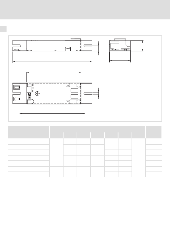
Mechanische Daten
Typ
E82ZM37132B002
E82ZM75134B004
E82ZM75134B005
E82ZM22234B004
E82ZM22234B005
E82ZM11334B004
E82ZM11334B005
e3
b
b1
b2
Maße [mm] Masse
a b b1 b2 e1 e3 m [kg]
225 154 185
300 229 260
60
350 279 305
100 350 279 305
a
m
30 15
60 2.4
30 15 1.0
60 2.6
30 15 1.3
60 30 4.1
e1
6.5
E82ZM−006
0.6
0.9
14
l
EDK82ZM113−001 DE/EN/FR 1.1
Page 15

Mechanische Installation
Wichtige Hinweise
3 Mechanische Installation
Wichtige Hinweise
ƒ Der Montageort muss den in den Technischen Daten genannten Einsatzbedingungen
immer entsprechen (^ 11). Ggf. zusätzliche Maßnahmen ergreifen.
ƒ Die Montageplatte des Schaltschranks muss folgende Eigenschaften aufweisen:
– elektrisch leitfähig
– lackfrei
ƒ Die mechanischen Verbindungen müssen immer gewährleistet sein.
ƒ Das Motor−Entstörmodul kann in zwei Varianten montiert werden:
– Standard−Montage: Das Grundgerät wird auf dem Entstörmodul montiert.
– Montage−Variante: Das Grundgerät wird links neben dem Entstörmodul montiert.
Die Grundgeräte E82xV552Kx, E82xV752Kx und E82xV113K4 sind breiter als das Entstörmodul. Bei diesen Grundgeräten muss die Montage−Variante angewendet werden.
3
EDK82ZM113−001 DE/EN/FR 1.1
l
15
Page 16
3 Mechanische Installation
Montageschritte
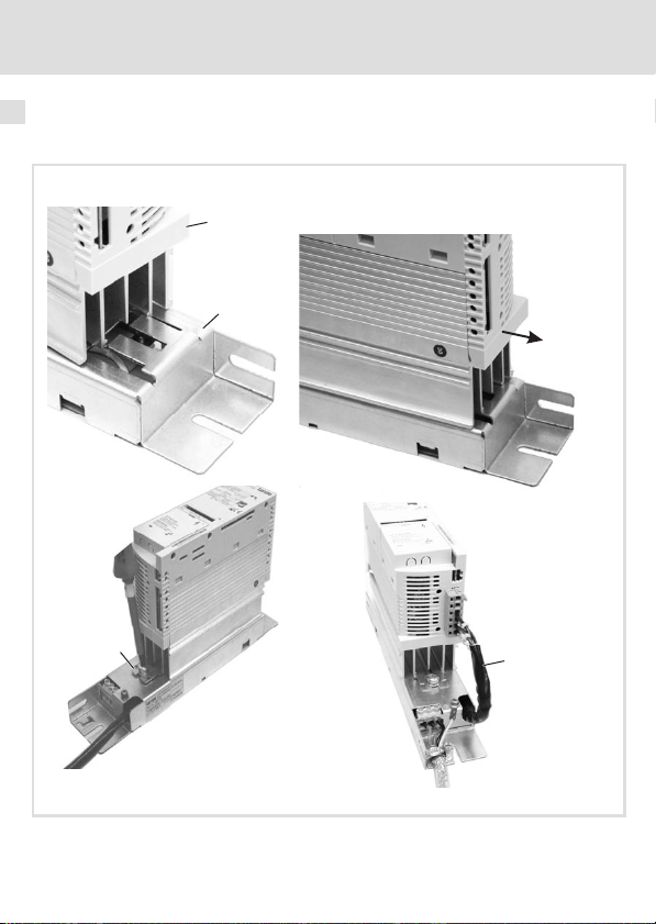
Montageschritte
Standard−Montage
0
1
2
3
E82ZM−003a
16
l
EDK82ZM113−001 DE/EN/FR 1.1
Page 17

Mechanische Installation
Montageschritte
So montieren Sie das Filter
1. Frequenzumrichter 0 auf das Gehäuse des Motor−Entstörmoduls 1 setzen.
2. Frequenzumrichter auf die Befestigungsschiene des Motor−Entstörmoduls schieben.
3. Befestigungsschiene 2 in die Kühlkörpernut des Grundgerätes schieben und
Frequenzumrichter und Motor−Entstörmodul miteinander verschrauben.
4. Anschlussleitung des Motor−Entstörmoduls 3 an die Anschlussklemmen des
Grundgeräts (U, V, W und PE) anschließen (^ 20). Dokumentation zum Grundgerät
beachten!
5. Einheit im Schaltschrank montieren.
3
EDK82ZM113−001 DE/EN/FR 1.1
l
17
Page 18
3 Mechanische Installation
Montageschritte
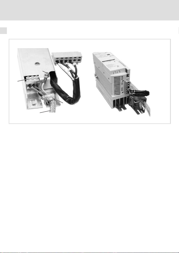
Montage−Variante
2
1
3
So montieren Sie das Filter
1. Motorleitung 0 auflegen, da nach der mechanischen Montage bei einigen Typen die
Anschlussklemmen nicht mehr zugänglich sind.
– Motorleitung an den Klemmen U’, V’, W’ 1 bzw. an der PE−Schraube 2 auflegen
– Schirmung der Motorleitung großflächig auf die rechte Schirmauflage auflegen
2. Entstörmodul im Schaltschrank, rechts neben dem Grundgerät montieren.
Nur so verhindern Sie eine Leitungsschleife.
0
E82ZM−003b
(^ 20).
und mit der Schirmschelle 3 (im Lieferumgang) befestigen.
18
l
EDK82ZM113−001 DE/EN/FR 1.1
Page 19

Elektrische Installation
Wichtige Hinweise
4 Elektrische Installation
Wichtige Hinweise
ƒ Die Installation muss
– den in den Technischen Daten genannten Einsatzbedingungen immer
entsprechen (^ 11).
– nach EN 60204−1 ausgeführt werden.
ƒ Bei der Auswahl des Leitungstyps beachten:
– Die verwendeten Leitungen müssen den geforderten Approbationen am
Einsatzort entsprechen (z. B. VDE, UL usw.).
– Absicherung und Leitungsquerschnitte gemäß den Vorgaben in der
Dokumentation zum Grundgerät bemessen.
ƒ Beim Verlegen der PE−Leitung beachten:
– Der PE−Anschluss muss nach EN 61800−5−1 ausgeführt werden.
4
EDK82ZM113−001 DE/EN/FR 1.1
l
19
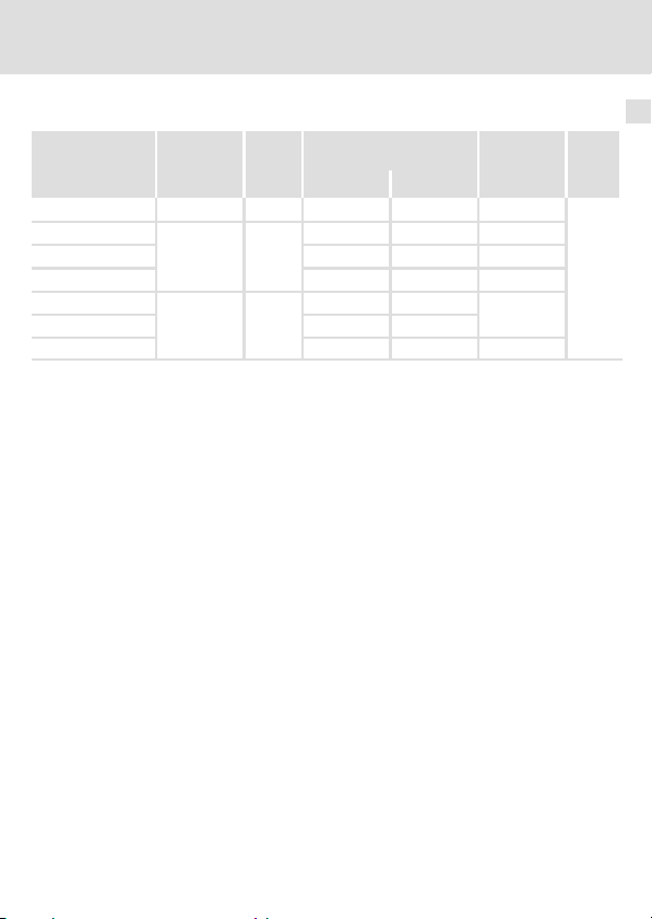
Page 20

4 Elektrische Installation
Anschlussplan
Anschlussplan
E8xVxxxKx
UVWPEPE
U
W
E82ZMxxxxxBxxx
U1VV1
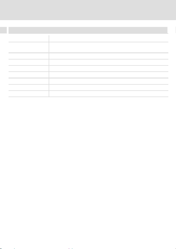
Anschlussdaten
PE
W1
M
3~
E82ZM−004
E82ZM37132B002
E82ZM75134B004
E82ZM22234B004
E82ZM11334B004
E82ZM75134B005
E82ZM22234B005
E82ZM11334B005
20
0.2 ... 4
[mm2] [AWG] [mm]
0.5 ... 2.5
0.25 ... 4
0.5 ... 1.5
l
24 ... 10 8
EDK82ZM113−001 DE/EN/FR 1.1
[Nm]
[lb−in]
0.5 ... 0.8
4.4 ... 7.1
0.6 ... 0.8
5.3 ... 7.1
Page 21

Elektrische Installation
Montageschritte
Montageschritte
2
1
0
3
E82ZM−005
So schließen Sie das Entstörmodul an:
1. Schaltschrank spannungsfrei schalten und gegen Wiedereinschalten sichern.
2. Mindestens 3 Minuten warten, dann Spannungsfreiheit des Grundgerätes prüfen.
3. Anschlussleitung des Motor−Entstörmoduls 0 an die Anschlussklemmen des
Grundgeräts (U, V, W und PE) anschließen.
– Dokumentation zum Grundgerät beachten!
4. Motorleitung auflegen.
– Motorleitung an den Klemmen U’, V’, W’ 1 bzw. an der PE−Schraube 2 auflegen.
– Schirmung der Motorleitung großflächig auf die rechte Schirmauflage auflegen
und mit der Schirmschelle 3 (im Lieferumgang) befestigen.
4
EDK82ZM113−001 DE/EN/FR 1.1
l
21
Page 22

0Fig. 0Tab. 0
Scope of supply
Quantity Description
1 Filter
1 Mounting Instructions
Elements on the filter
Position Description
0
1
2
3
4
5
Validity information
These instructions are valid for
ƒ Motor interference suppression module E82ZM37132B002
ƒ Motor interference suppression module E82ZM75134B004
ƒ Motor interference suppression module E82ZM11334B004
ƒ Motor interference suppression module E82ZM22234B004
ƒ Motor interference suppression module E82ZM75134B005
ƒ Motor interference suppression module E82ZM22234B005
ƒ Motor interference suppression module E82ZM11334B005
Mounting spots in the standard device for footprint mounting (standard)
Nameplate
Input connecting cable (U, V, W, PE)
Shield connection, shield clamp
Motor cable terminals (U1, V1, W1)
PE terminal screw for the motor cable
22
l
EDK82ZM113−001 DE/EN/FR 1.1
Page 23

Identification
L
xxxxxxxxxxxxxxxx
Art.-Nr. / Part No.:
Typ / Type:
xxxxxxxxxxxxxxxxxxxxxx
xxxxxxxxxxxxxxxxxxxxxxxxxxxxxxxxxxxxxxxx
Fig. 1 Nameplate
xxxxxx
E82ZZ37112B200
E82ZZ005
Type code
E82 Z m xxx 3 x b xxx
Product series
Accessories
Type
M = filter on the motor side
Power
e.g. 752 = 75 x 10
e.g. 113 = 11 x 103 W = 11 kW
Number of phases
3 = 3 phases
Voltage class
2 = 230 V
4 = 400/500 V
Device generation
Variant
2
W = 7.5 kW
EDK82ZM113−001 DE/EN/FR 1.1
l
23
Page 24

Application range
A motor interference suppression module is applied to reduce interference currents in the
motor cable.
Assignment of filters to standard devices
Type of filter
8200 vector 9300 vector 9300 servo
E82ZM37132B002 E82xV251K2
E82ZM75134B004 E82xV551Kx
E82ZM11334B004 E82xV302Kx
E82ZM75134B005 E82xV551K4
E82ZM22234B004 E82xV152Kx
E82ZM22234B005 E82xV152K4
E82ZM11334B005 E82xV302K4
E82xV371K2
E82xV751Kx
E82xV402Kx
E82xV552Kx
E82xV752Kx
E82xV113K4
E82xV751K4
E82xV222Kx
E82xV222K4
E82xV402K4
E82xV552K4
E82xV752K4
E82xV113K4
Type of controller
− −
− −
− −
− −
− −
− −
− −
24
l
EDK82ZM113−001 DE/EN/FR 1.1
Page 25

Document history
Material number Version Description
.6aZ 1.1 07/2010 TD29 Change of company name
13216457 1.0 11/2007 TD29 Separate reprint, replaces
EDK82ZM113 (00453091)
I Tip!
Documentation and software updates for further Lenze products can be found
on the Internet in the "Services & Downloads" area under
http://www.Lenze.com
EDK82ZM113−001 DE/EN/FR 1.1
l
25
Page 26

i Contents
1 Safety instructions 27 . . . . . . . . . . . . . . . . . . . . . . . . . . . . . . . . . . . . . . . . . . . . . . . . .
Notes used 27 . . . . . . . . . . . . . . . . . . . . . . . . . . . . . . . . . . . . . . . . . . . . . . . . . . . . . . . .
Residual hazards 28 . . . . . . . . . . . . . . . . . . . . . . . . . . . . . . . . . . . . . . . . . . . . . . . . . . .
2 Technical data 29 . . . . . . . . . . . . . . . . . . . . . . . . . . . . . . . . . . . . . . . . . . . . . . . . . . . . .
General data and operating conditions 29 . . . . . . . . . . . . . . . . . . . . . . . . . . . . . . .
Rated data 31 . . . . . . . . . . . . . . . . . . . . . . . . . . . . . . . . . . . . . . . . . . . . . . . . . . . . . . . .
Mechanical data 32 . . . . . . . . . . . . . . . . . . . . . . . . . . . . . . . . . . . . . . . . . . . . . . . . . .
3 Mechanical installation 33 . . . . . . . . . . . . . . . . . . . . . . . . . . . . . . . . . . . . . . . . . . . . .
Important notes 33 . . . . . . . . . . . . . . . . . . . . . . . . . . . . . . . . . . . . . . . . . . . . . . . . . . .
Mounting steps 34 . . . . . . . . . . . . . . . . . . . . . . . . . . . . . . . . . . . . . . . . . . . . . . . . . . . .
4 Electrical installation 37 . . . . . . . . . . . . . . . . . . . . . . . . . . . . . . . . . . . . . . . . . . . . . . .
Important notes 37 . . . . . . . . . . . . . . . . . . . . . . . . . . . . . . . . . . . . . . . . . . . . . . . . . . .
Connection plan 38 . . . . . . . . . . . . . . . . . . . . . . . . . . . . . . . . . . . . . . . . . . . . . . . . . . .
Connection data 38 . . . . . . . . . . . . . . . . . . . . . . . . . . . . . . . . . . . . . . . . . . . . . . . . . . .
Mounting steps 39 . . . . . . . . . . . . . . . . . . . . . . . . . . . . . . . . . . . . . . . . . . . . . . . . . . . .
26
l
EDK82ZM113−001 DE/EN/FR 1.1
Page 27

Safety instructions
Notes used
1 Safety instructions
Notes used
The following pictographs and signal words are used in this documentation to indicate
dangers and important information:
Safety instructions
Structure of safety instructions:
} Danger!
(characterises the type and severity of danger)
Note
(describes the danger and gives information about how to prevent dangerous
situations)
Pictograph and signal word Meaning
Danger of personal injury through dangerous electrical
voltage.
{ Danger!
} Danger!
( Stop!
Reference to an imminent danger that may result in
death or serious personal injury if the corresponding
measures are not taken.
Danger of personal injury through a general source of
danger.
Reference to an imminent danger that may result in
death or serious personal injury if the corresponding
measures are not taken.
Danger of property damage.
Reference to a possible danger that may result in
property damage if the corresponding measures are not
taken.
1
EDK82ZM113−001 DE/EN/FR 1.1
l
27
Page 28

1 Safety instructions
Residual hazards
Application notes
Pictograph and signal word Meaning
) Note!
I Tip!
,
Residual hazards
Important note to ensure troublefree operation
Useful tip for simple handling
Reference to another documentation
{ Danger!
Dangerous voltage
All power connections carry dangerous voltages both if the motor is at
standstill and after up to 3 minutes after mains switch off.
Possible consequences:
ƒ Death or severe injuries after touching the power connections.
Protective measures:
ƒ Wait for at least 3 minutes before working on the power connections.
ƒ Check whether all power connections are de−energised.
{ Danger!
Dangerous voltage
The leakage current to earth (PE) is > 3.5 mA AC or > 10 mA DC.
Possible consequences:
ƒ Death or severe injuries when the device is touched in the event of a fault.
Protective measures:
ƒ Implement the actions required in the EN 61800−5−1. Especially:
– Fixed installation
– PE connection must conform to standards (PE conductor diameter
³ 10 mm
2
or PE conductor must be connected twice)
28
l
EDK82ZM113−001 DE/EN/FR 1.1
Page 29

General data and operating conditions
Technical data
2 Technical data
General data and operating conditions
Protection
Type of protection
Insulation resistance EN 61800−5−1 Overvoltage category III
Leakage current EN 61800−5−1 > 3.5 mA Observe regulations
Ambient conditions
Temperature
Storage
Transport −25 ... +70 °C
Operation −10 ... +55 °C
Site altitude 0 ... 4000 m amsl
Pollution EN 61800−5−1 Pollution degree 2
Vibration resistance EN 50178; IEC
EN 60529
NEMA 250 Protection against contact to
61800−5−1;
Germanischer
Lloyd, general
conditions
IP 20
type 1
> 2000 m: Overvoltage category II
−25 ... +60 °C
Current derating from +40 to +55 °C: 2.5 %/°C
1000 ... 4000 m amsl: Current derating by 5 %/1000 m
Acceleration−resistant up to 0.7 g
Not in the wire range of
the terminals
and safety instructions!
2
EDK82ZM113−001 DE/EN/FR 1.1
l
29
Page 30

2 Technical data
General data and operating conditions
Mounting conditions
Mounting location In the control cabinet
Mounting position Standard: between mounting plate and basic device
Mounting position vertical
Free spaces
at the top > 90 mm
at the bottom > 100 mm
to the sides > 3 mm
Connecting cables
Filter « Motor
1) Motor cables must comply with EMC limit values only with regard to conducted interference
emission.
2) Max. motor cable length at a switching frequency of 16 kHz:
E82ZM22234B004, E82ZM75134B004, E82ZM11334B004 = 10 m
E82ZM75134B005, E82ZM22234B005 and E82ZM11334B005 = 25 m
Variant: to the right of the basic device
Max. 50 m when shielded, low−capacitance, or max. 100 m when
unshielded
1) 2)
30
l
EDK82ZM113−001 DE/EN/FR 1.1
Page 31

Technical data
Rated data
Voltage Freque
Type [V] [Hz] up to +40 °Cup to +55 °C[W]
E82ZM37132B002 240 0 ... 650 2.4 1.5 12
E82ZM75134B004
E82ZM22234B004 9.5/6.7 5.9/4.2 20
E82ZM11334B004 28.6/23.5 17.9/14.7 30
E82ZM75134B005
E82ZM22234B005 6.7/4.5 4.2/2.8
E82ZM11334B005 23.5/18.8 14.7/11.7 80
1) Max. output frequency at a switching frequency of 16 kHz = 100 Hz
240/400
400/500 0 ... 650
ncy
0 ... 650
1)
Temperature in the control cabinet
Current [A] Power loss
4.8/2.9 3.0/1.8 50
2.9/1.9 1.8/1.2
Rated data
Numbe
40
r of
phases
3
2
EDK82ZM113−001 DE/EN/FR 1.1
l
31
Page 32

2 Technical data
Mechanical data
Mechanical data
Type
E82ZM37132B002
E82ZM75134B004
E82ZM75134B005
E82ZM22234B004
E82ZM22234B005
E82ZM11334B004
E82ZM11334B005
e3
b
b1
b2
Dimensions [mm] Mass
a b b1 b2 e1 e3 m [kg]
225 154 185
300 229 260
60
350 279 305
100 350 279 305
a
m
30 15
60 2.4
30 15 1.0
60 2.6
30 15 1.3
60 30 4.1
e1
6.5
E82ZM−006
0.6
0.9
32
l
EDK82ZM113−001 DE/EN/FR 1.1
Page 33

Mechanical installation
Important notes
3 Mechanical installation
Important notes
ƒ The mounting location must always fulfill the operating conditions specified in the
Technical data. (^ 29). If necessary, take additional measures.
ƒ The mounting plate of the control cabinet must be:
– electrically conductive
– free of lacquer
ƒ The mechanical connections must always be ensured.
ƒ The motor interference suppression module can be mounted in two different ways:
– Standard mounting: the standard device is mounted to the interference
suppression module.
– Mounting variant: the standard device is mounted to the left side of the
interference suppression module.
The standard devices E82xV552Kx, E82xV752Kx and E82xV113K4 are of greater width
than the interference suppression module. Here, the mounting variant must be applied.
3
EDK82ZM113−001 DE/EN/FR 1.1
l
33
Page 34

3 Mechanical installation
Mounting steps
Mounting steps
Standard mounting
0
1
2
3
E82ZM−003a
34
l
EDK82ZM113−001 DE/EN/FR 1.1
Page 35

Mechanical installation
Mounting steps
How to mount the filter:
1. Put the frequency inverter 0 on the housing of the motor interference suppression
module 1.
2. Move the frequency inverter to the fixing rail of the motor interference suppression
module.
3. Move the fixing rail 2 to the heatsink slot of the standard device and screw the
frequency inverter and the motor interference suppression module together.
4. Connect the connecting cable of the motor interference suppression module 3 to the
terminals of the standard device (U, V, W, and PE). (^ 38). Observe the
documentation of the standard device!
5. Mount the unit to the control cabinet.
3
EDK82ZM113−001 DE/EN/FR 1.1
l
35
Page 36

3 Mechanical installation
Mounting steps
Mounting variant
2
1
3
How to mount the filter:
1. Apply the motor cable 0 since for some types the terminals are no longer accessible
after a mechanical mounting.
– Apply the motor cable to the terminals U’, V’, W’ 1 and to the PE screw2,
– Apply the motor cable shielding extensively to the shield connection on the right
2. Mount the interference suppression module to the control cabinet to the right of the
standard device.
This is the only way to avoid loops.
0
E82ZM−003b
respectively. (^ 38).
hand side and fix it using the shield clamp 3(included in the scope of supply).
36
l
EDK82ZM113−001 DE/EN/FR 1.1
Page 37

Electrical installation
Important notes
4 Electrical installation
Important notes
ƒ Installation must
– always be in accordance with the operating conditions specified in the Technical
data (^ 29).
– be carried out to EN 60204−1.
ƒ Please observe the following when selecting the cable type:
– The cables used must comply with the approvals required for the application (e. g.
VDE, UL etc.).
– Fuses and cable cross−sections must be dimensioned in accordance with the
specifications in the documentation for the basic device.
ƒ Please observe the following when laying the PE cable:
– The PE connection must comply with EN 61800−5−1.
4
EDK82ZM113−001 DE/EN/FR 1.1
l
37
Page 38

4 Electrical installation
Connection plan
Connection plan
E8xVxxxKx
UVWPEPE
U
W
E82ZMxxxxxBxxx
U1VV1
Connection data
PE
W1
M
3~
E82ZM−004
E82ZM37132B002
E82ZM75134B004
E82ZM22234B004
E82ZM11334B004
E82ZM75134B005
E82ZM22234B005
E82ZM11334B005
38
0.2 ... 4
[mm2] [AWG] [mm]
0.5 ... 2.5
0.25 ... 4
0.5 ... 1.5
l
24 ... 10 8
EDK82ZM113−001 DE/EN/FR 1.1
[Nm]
[lb−in]
0.5 ... 0.8
4.4 ... 7.1
0.6 ... 0.8
5.3 ... 7.1
Page 39

Electrical installation
Mounting steps
Mounting steps
2
1
0
3
E82ZM−005
How to connect the interference suppression module:
1. De−energise the control cabinet and fuse it against re−energisation.
2. Wait for at least 3 minutes before checking the standard device for isolation from
supply.
3. Connect the connecting cable of the motor interference suppression module 0 to the
terminals of the standard device (U, V, W, and PE).
– Observe the documentation of the standard device!
4. Apply the motor cable.
– Apply the motor cable to the terminals U’, V’, W’ 1 and to the PE screw 2,
respectively.
– Apply the motor cable shielding extensively to the shield connection on the right
hand side and fix it using the shield clamp 3(included in the scope of supply).
4
EDK82ZM113−001 DE/EN/FR 1.1
l
39
Page 40

0Fig. 0Tab. 0
Equipement livré
Nombre Description
1 Filtre
1 Instructions de montage
Eléments du filtre
Position Description
0
1
2
3
4
5
Informations relatives à la validité
Le présent document s’applique au produit suivant :
ƒ Module d’antiparasitage moteur E82ZM37132B002
ƒ Module d’antiparasitage moteur E82ZM75134B004
ƒ Module d’antiparasitage moteur E82ZM11334B004
ƒ Module d’antiparasitage moteur E82ZM22234B004
ƒ Module d’antiparasitage moteur E82ZM75134B005
ƒ Module d’antiparasitage moteur E82ZM22234B005
ƒ Module d’antiparasitage moteur E82ZM11334B005
Points de montage arrière de l’appareil de base (standard)
Plaque signalétique
Câble d’entrée (U, V, W, PE)
Reprise du blindage, collier de blindage
Bornes de raccordement câble moteur (U1, V1, W1)
Vis PE câble moteur
40
l
EDK82ZM113−001 DE/EN/FR 1.1
Page 41

Identification
L
xxxxxxxxxxxxxxxx
Art.-Nr. / Part No.:
Typ / Type:
xxxxxxxxxxxxxxxxxxxxxx
xxxxxxxxxxxxxxxxxxxxxxxxxxxxxxxxxxxxxxxx
Fig. 1 Plaque signalétique
xxxxxx
E82ZZ37112B200
E82ZZ005
Codification
des types
E82 Z m xxx 3 x b xxx
Série
d’appareils
Accessoires
Type
M = filtre côté moteur
Puissance
p. ex. 752 = 75 x 10
p. ex. 113 = 11 x 103 W = 11 kW
Nombre de phases
3 = 3 phases
Classe de tension
2 = 230 V
4 = 400/500 V
Génération d’appareils
Variante
2
W = 7,5 kW
EDK82ZM113−001 DE/EN/FR 1.1
l
41
Page 42

Utilisation
Utiliser un module d’antiparasitage moteur pour réduire les interférences dans le câble
moteur.
Combinaisons filtre ˘ appareil de base
Type de filtre
8200 vector 9300 vector 9300 servo
E82ZM37132B002 E82xV251K2
E82ZM75134B004 E82xV551Kx
E82ZM11334B004 E82xV302Kx
E82ZM75134B005 E82xV551K4
E82ZM22234B004 E82xV152Kx
E82ZM22234B005 E82xV152K4
E82ZM11334B005 E82xV302K4
E82xV371K2
E82xV751Kx
E82xV402Kx
E82xV552Kx
E82xV752Kx
E82xV113K4
E82xV751K4
E82xV222Kx
E82xV222K4
E82xV402K4
E82xV552K4
E82xV752K4
E82xV113K4
Type d’appareil
− −
− −
− −
− −
− −
− −
− −
42
l
EDK82ZM113−001 DE/EN/FR 1.1
Page 43

Historique du document
Numéro de document Version Description
.6aZ 1.1 07/2010 TD29 Nouveau nom commercial
13216457 1.0 11/2007 TD29 Réédition segmentée,
remplace EDK82ZM113
(00453091)
I Conseil !
Les mises à jour de logiciels et les documentations relatives aux produits Lenze
sont disponibles dans la zone "Services & Downloads" du site Internet :
http://www.Lenze.com
EDK82ZM113−001 DE/EN/FR 1.1
l
43
Page 44

i Sommaire
1 Consignes de sécurité 45 . . . . . . . . . . . . . . . . . . . . . . . . . . . . . . . . . . . . . . . . . . . . . . .
Consignes utilisées 45 . . . . . . . . . . . . . . . . . . . . . . . . . . . . . . . . . . . . . . . . . . . . . . . . .
Dangers résiduels 47 . . . . . . . . . . . . . . . . . . . . . . . . . . . . . . . . . . . . . . . . . . . . . . . . . .
2 Spécifications techniques 48 . . . . . . . . . . . . . . . . . . . . . . . . . . . . . . . . . . . . . . . . . . .
Caractéristiques générales et conditions d’utilisation 48 . . . . . . . . . . . . . . . . . . . .
Caractéristiques assignées 50 . . . . . . . . . . . . . . . . . . . . . . . . . . . . . . . . . . . . . . . . . . .
Caractéristiques mécaniques 51 . . . . . . . . . . . . . . . . . . . . . . . . . . . . . . . . . . . . . . . .
3 Installation mécanique 52 . . . . . . . . . . . . . . . . . . . . . . . . . . . . . . . . . . . . . . . . . . . . . .
Remarques importantes 52 . . . . . . . . . . . . . . . . . . . . . . . . . . . . . . . . . . . . . . . . . . . . .
Opérations de montage 53 . . . . . . . . . . . . . . . . . . . . . . . . . . . . . . . . . . . . . . . . . . . . .
4 Installation électrique 55 . . . . . . . . . . . . . . . . . . . . . . . . . . . . . . . . . . . . . . . . . . . . . . .
Remarques importantes 55 . . . . . . . . . . . . . . . . . . . . . . . . . . . . . . . . . . . . . . . . . . . . .
Schéma de câblage 56 . . . . . . . . . . . . . . . . . . . . . . . . . . . . . . . . . . . . . . . . . . . . . . . . .
Données de raccordement 56 . . . . . . . . . . . . . . . . . . . . . . . . . . . . . . . . . . . . . . . . . . .
Opérations de montage 57 . . . . . . . . . . . . . . . . . . . . . . . . . . . . . . . . . . . . . . . . . . . . .
44
l
EDK82ZM113−001 DE/EN/FR 1.1
Page 45

Consignes de sécurité
Consignes utilisées
1 Consignes de sécurité
Consignes utilisées
Pour indiquer des risques et des informations importantes, la présente documentation
utilise les mots et symboles suivants :
Consignes de sécurité
Présentation des consignes de sécurité
} Danger !
(Le pictogramme indique le type de risque.)
Explication
(L’explication décrit le risque et les moyens de l’éviter.)
Pictogramme et mot associé Explication
Situation dangereuse pour les personnes en raison d’une
tension électrique élevée
{ Danger !
} Danger !
( Stop !
Indication d’un danger imminent qui peut avoir pour
conséquences des blessures mortelles ou très graves en
cas de non−respect des consignes de sécurité
correspondantes
Situation dangereuse pour les personnes en raison d’un
danger d’ordre général
Indication d’un danger imminent qui peut avoir pour
conséquences des blessures mortelles ou très graves en
cas de non−respect des consignes de sécurité
correspondantes
Risques de dégâts matériels
Indication d’un risque potentiel qui peut avoir pour
conséquences des dégâts matériels en cas de non−respect
des consignes de sécurité correspondantes
1
EDK82ZM113−001 DE/EN/FR 1.1
l
45
Page 46

1 Consignes de sécurité
Consignes utilisées
Consignes d’utilisation
Pictogramme et mot associé Explication
) Remarque
importante !
I Conseil !
,
Remarque importante pour assurer un fonctionnement
correct
Conseil utile pour faciliter la mise en oeuvre
Référence à une autre documentation
46
l
EDK82ZM113−001 DE/EN/FR 1.1
Page 47

Consignes de sécurité
Dangers résiduels
Dangers résiduels
{ Danger !
Tension électrique dangereuse
Une tension électrique dangereuse circule dans tous les raccordements de
puissance, même à l’arrêt et jusqu’à 3 minutes après une coupure réseau.
Risques encourus :
ƒ Mort ou blessures graves en cas de contact accidentel avec les
raccordements de puissance.
Mesures de protection :
ƒ Attendre au moins 3 minutes avant toute intervention sur les
raccordements de puissance.
ƒ S’assurer que tous les raccordements de puissance sont hors tension.
{ Danger !
Tension électrique dangereuse
Le courant de fuite vers la terre (PE) est > 3.5 mA CA ou > 10 mA CC.
Risques encourus
ƒ Mort ou blessures graves en cas de contact accidentel avec l’appareil en
défaut
Mesures de protection
ƒ Appliquer les dispositions prescrites par la norme EN 61800−5−1. Assurer,
en particulier,
– une installation fixe,
– le raccordement PE conformément à la norme (section de câble PE
³ 10 mm2 ou double raccordement du câble PE).
1
EDK82ZM113−001 DE/EN/FR 1.1
l
47
Page 48

2 Spécifications techniques
Caractéristiques générales et conditions d’utilisation
2 Spécifications techniques
Caractéristiques générales et conditions d’utilisation
Protection
Indice de protection
Résistance d’isolement EN 61800−5−1 Catégorie de surtension III
Courant de fuite EN 61800−5−1 > 3.5 mA Tenir compte des
Conditions climatiques
Température
Stockage −25 ... +60 °C
Transport −25 ... +70 °C
Fonctionnement −10 ... +55 °C
Altitude d’implantation 0 ... 4000 m au−dessus du niveau de la mer
Pollution ambiante
admissible
Résistance aux chocs EN50178 ;
EN 60529
NEMA 250 Protection contre contacts
EN 61800−5−1 Degré de pollution 2
IEC61800−5−1 ;
Germanischer
Loyd, Conditions
générales
IP 20
accidentels selon type 1
Réduction à partir de 2000 m : catégorie de
surtension II
Réduction de courant entre +40 et +55 °C : 2,5 %/°C
1000 ... 4000 m au−dessus du niveau de la mer :
réduction de courant de 5 %/1000 m
Résistance à l’accélération jusqu’à 0,7 g
Pas dans la zone de
raccordement des
bornes
prescriptions et des
consignes de sécurité !
48
l
EDK82ZM113−001 DE/EN/FR 1.1
Page 49

Caractéristiques générales et conditions d’utilisation
Spécifications techniques
Conditions de montage
Lieu de montage Armoire électrique
Position de montage Standard : entre la plaque de montage et l’appareil de base
Orientation de
montage
Espaces de montage
En haut > 90 mm
En bas > 100 mm
Sur le côté > 3 mm
Câbles de
raccordement
Filtre « Moteur
1 Les câbles moteur doivent respecter les valeurs limites prescrites en matière de CEM uniquement
en matière de perturbations radioélectriques transmises par câble.
2) Longueur de câble max. avec une fréquence de découpage 16 kHz :
E82ZM22234B004, E82ZM75134B004, E82ZM11334B004 = 10 m
E82ZM75134B005, E82ZM22234B005 und E82ZM11334B005 = 25 m
Variante : à droite de l’appareil de base
Verticale
50 m max. avec câble blindé de faible capacité ou 100 m max. avec câble
1) 2)
non blindé
2
EDK82ZM113−001 DE/EN/FR 1.1
l
49
Page 50

2 Spécifications techniques
Caractéristiques assignées
Caractéristiques assignées
Tension Fréque
Type [V] [Hz] Jusqu’à +40
E82ZM37132B002 240 0 ... 650 2.4 1.5 12
E82ZM75134B004
E82ZM22234B004 9.5/6.7 5.9/4.2 20
E82ZM11334B004 28.6/23.5 17.9/14.7 30
E82ZM75134B005
E82ZM22234B005 6.7/4.5 4.2/2.8
E82ZM11334B005 23.5/18.8 14.7/11.7 80
1) Fréquence de sortie max. pour une fréquence de découpage de 16 kHz = 100 Hz
Température dans l’armoire électrique
240/400
400/500 0 ... 650
nce
0 ... 650
1)
Courant [A] Puissance
°C
4.8/2.9 3.0/1.8 50
2.9/1.9 1.8/1.2
Jusqu’à +55
°C
dissipée
[W]
40
Nombr
e de
phases
3
50
l
EDK82ZM113−001 DE/EN/FR 1.1
Page 51

Caractéristiques mécaniques
Spécifications techniques
Caractéristiques mécaniques
2
Type
E82ZM37132B002
E82ZM75134B004
E82ZM75134B005
E82ZM22234B004
E82ZM22234B005
E82ZM11334B004
E82ZM11334B005
e3
b
b1
b2
Cotes [mm] Poids
a b b1 b2 e1 e3 m [kg]
225 154 185
300 229 260
60
350 279 305
100 350 279 305
a
m
30 15
60 2.4
30 15 1.0
60 2.6
30 15 1.3
60 30 4.1
e1
6.5
E82ZM−006
0.6
0.9
EDK82ZM113−001 DE/EN/FR 1.1
l
51
Page 52

3 Installation mécanique
Remarques importantes
3 Installation mécanique
Remarques importantes
ƒ Le lieu de montage doit toujours respecter les conditions d’utilisation indiquées dans
les spécifications techniques (^ 48). Si besoin est, prendre des mesures
supplémentaires.
ƒ La plaque de montage de l’armoire électrique doit être :
– conductrice,
– exempte de vernis.
ƒ Les liaisons mécaniques doivent toujours être assurées.
ƒ Il existe deux possibilités de montage du module d’antiparasitage moteur :
– Montage standard : l’appareil de base est monté sur le module d’antiparasitage.
– Variante : l’appareil de base est monté à gauche du module d’antiparasitage.
Les appareils de base E82xV552Kx, E82xV752Kx et E82xV113K4 sont plus larges que le
module d’antiparasitage. Pour ces appareils, la seconde variante est la seule possible.
52
l
EDK82ZM113−001 DE/EN/FR 1.1
Page 53

Opérations de montage
Montage standard
Installation mécanique
Opérations de montage
3
0
1
2
3
E82ZM−003a
EDK82ZM113−001 DE/EN/FR 1.1
l
53
Page 54

3 Installation mécanique
Opérations de montage
Pour monter le filtre :
1. Placer le convertisseur de fréquence 0 sur le boîtier du module d’antiparasitage
moteur 1.
2. Faire glisser le convertisseur de fréquence sur le profilé de fixation du module
d’antiparasitage moteur.
3. Faire glisser le profilé de fixation 2 dans la rainure du radiateur de l’appareil de base
et assembler le convertisseur de fréquence et le module d’antiparasitage moteur.
4. Relier le câble du module d’antiparasitage moteur 3 aux bornes de raccordement de
l’appareil de base (U, V, W et PE) (^ 56). Lire la documentation de l’appareil de base !
5. Monter l’unité dans l’armoire électrique.
Variante de montage
2
1
3
0
E82ZM−003b
Pour monter le filtre :
1. Brancher le câble moteur 0, car sur certains types, les bornes de raccordement ne
sont plus accessibles après l’installation mécanique.
– Relier le câble moteur aux bornes U’, V’, W’ 1ou à la vis PE 2 (^ 56).
– Poser le blindage du câble moteur sur la reprise de blindage de droite en
appliquant une surface de contact importante et le fixer à l’aide du collier de
blindage 3(livré avec l’équipement).
2. Monter le module d’antiparasitage dans l’armoire électrique, à droite de l’appareil de
base.
Vous éviterez ainsi la formation d’une boucle de ligne.
54
l
EDK82ZM113−001 DE/EN/FR 1.1
Page 55

Installation électrique
Remarques importantes
4 Installation électrique
Remarques importantes
ƒ L’installation doit
– toujours respecter les conditions d’utilisation indiquées dans les spécifications
techniques (^ 48) ;
– répondre aux exigences de la norme EN 60204−1.
ƒ Lors du choix du type de câble, tenir compte des points suivants :
– Les câbles utilisés doivent être conformes aux homologations requises sur le lieu
d’utilisation (exemples : VDE, UL, etc.).
– Les fusibles et les sections de câble doivent être dimensionnés conformément aux
prescriptions figurant dans la documentation de l’appareil de base.
ƒ Lors de la pose du câble PE, tenir compte du point suivant :
– Le raccordement PE doit être effectué conformément à la norme EN 61800−5−1.
4
EDK82ZM113−001 DE/EN/FR 1.1
l
55
Page 56

4 Installation électrique
Schéma de câblage
Schéma de câblage
E8xVxxxKx
UVWPEPE
U
W
E82ZMxxxxxBxxx
U1VV1
Données de raccordement
PE
W1
M
3~
E82ZM−004
E82ZM37132B002
E82ZM75134B004
E82ZM22234B004
E82ZM11334B004
E82ZM75134B005
E82ZM22234B005
E82ZM11334B005
56
0.2 ... 4
[mm2] [AWG] [mm]
0.5 ... 2.5
0.25 ... 4
0.5 ... 1.5
l
24 ... 10 8
EDK82ZM113−001 DE/EN/FR 1.1
[Nm]
[lb−in]
0.5 ... 0.8
4.4 ... 7.1
0.6 ... 0.8
5.3 ... 7.1
Page 57

Installation électrique
Opérations de montage
Opérations de montage
2
1
0
3
E82ZM−005
Pour raccorder le module d’antiparasitage, procéder comme suit :
1. Couper la tension dans l’armoire électrique et s’assurer que toute mise sous tension
est exclue.
2. Attendre au moins 3 minutes puis s’assurer que l’appareil de base est hors tension.
3. Relier le câble du module d’antiparasitage moteur 0 aux bornes de raccordement de
l’appareil de base (U, V, W et PE).
– Tenir compte de la documentation de l’appareil de base !
4. Brancher le câble moteur.
– Relier le câble moteur aux bornes U’, V’, W’ 1ou à la vis PE 2.
– Poser le blindage du câble moteur sur la reprise de blindage de droite en
appliquant une surface de contact importante et le fixer à l’aide du collier de
blindage 3(livré avec l’équipement).
4
EDK82ZM113−001 DE/EN/FR 1.1
l
57
Page 58

© 07/2010
Lenze Automation GmbH
F
Hans−Lenze−Str. 1
D−31855 Aerzen
Germany
(
+49(0)51 54 /82−0
Ê
+49(0)51 54 /82 − 28 00
Lenze@Lenze.de
ü
www.Lenze.com
Service Lenze Service GmbH
Breslauer Straße 3
D−32699 Extertal
Germany
(
008000/ 2446877 (24 h helpline)
Ê
+49(0)5154/ 82−11 12
Service@Lenze.de
EDK82ZM113−001 § .6aZ § DE/EN/FR § 1.1 § TD29
10987654321
 Loading...