

Page 1
EDK82ZBX020
Show/Hide Bookmarks
00454680
Montageanleitung
Poti-Einheit E82ZBR020
06/02
Schalter-Einheit E82ZBS020
Diese Anleitung
beschreibt die Installation und die Handhabung der Poti-Einheit und der Schalter-Einheit.
ist nur gültig
- für Poti-Einheiten mit der Typenbezeichnung E82ZBR020.
- für Schalter-Einheiten mit der Typenbezeichnung E82ZBS020.
- zusammen mit der Betriebsanleitung des zugehörigen Antriebsreglers.
Beschreibung
Die Poti-Einheit E82ZBR020 ermöglicht die Vorgabe eines analogen Sollwertsignals für
Lenze-Antriebsregler über die Funktionsmodule Standard-I/O oder Application-I/O.
Die Schalter-Einheit E82ZBS020 ermöglicht die einfache Steuerung von Lenze-Antriebsreglern über
die Digitaleingänge der Funktionsmodule Standard-I/O oder Application-I/O (z. B.
Drehrichtungsumkehr).
Einsatzbereich
Einsetzbar mit
Frequenzumrichtern 8200 motec
Motorstartern starttec
Lieferumfang
Poti-Einheit Schalter-Einheit
1 Poti-Einheit komplett montiert, 10 kΩ 1 Schalter-Einheit komplett montiert
1 Aufkleber für Poti-Stellungen 1 Aufkleber für Schalterstellungen
Allgemeine Daten und Einsatzbedingungen
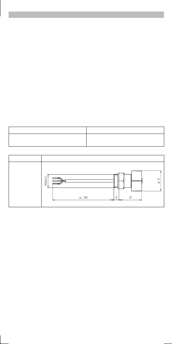
Schutzart IP55
Abmessungen
[mm]
Montagemöglichkeiten
Die Einheit wird in einer Bohrung M20 montiert.
Lenze Drive Systems GmbH, Postfach 10 13 52, D-31763 Hameln
l
( (+49) 5154 82-0, Fax Service: (+49) 5154 82-1112
E82ZBX001
EDK82ZBX020 3.0
Page 2

Poti-Einheit — Installation
Show/Hide Bookmarks
Poti-Einheit installieren und anschließen
1. Am Trägergehäuse Einbau-Öffnung M20 freibrechen oder Verschlusskappe entfernen.
2. Poti-Einheit von außen in die Einbau-Öffnung einschrauben.
- Schutzart IP55 bleibt durch vormontierten Dichtring erhalten.
3. Aufkleber auf das Trägergehäuse kleben.
4. Poti-Einheit an das Funktionsmodul anschließen.
5. Hardware und Software des motec für Sollwertbereich 0 ... 5 V konfigurieren:
- Schalter-/Jumperstellung am Funktionsmodul anpassen.
- C0034 anpassen.
l
-2-
EDK82ZBX020 3.0
Page 3
Poti-Einheit — Installation
X
E82ZAFA01
1
Show/Hide Bookmarks
Anschluß am Standard-I/O
STANDARD S
STANDARD S
STANDARD S
STANDARD S
STANDARD S
STANDARD S
STANDARD S
STANDARD S
ON
ON
ON
ON
ON
ON
ON
ON
1 2 3 4 5
1 2 3 4 5
1 2 3 4 5
1 2 3 4 5
1 2 3 4 5
1 2 3 4 5
1 2 3 4 5
1 2 3 4 5
A139
A139
A139
A139
A139
A139
A139
762 8 9720 28 E1 59E2E3E4
762 8 9720 28 E1 59E2E3E4
762 8 9720 28 E1 59E2E3E4
762 8 9720 28 E1 59E2E3E4
762 8 9720 28 E1 59E2E3E4
762 8 9720 28 E1 59E2E3E4
762 8 9720 28 E1 59E2E3E4
762 8 9720 28 E1 59E2E3E4
Anschluß am Application-I/O
APPLICATION A
APPLICATION A
APPLICATION A
APPLICATION A
APPLICATION A
APPLICATION A
APPLICATION A
APPLICATION A
APPLICATION A
APPLICATION A
APPLICATION A
APPLICATION A
5
5
5
5
5
5
5
5
5
5
5
5
3
3
3
3
3
3
3
3
3
3
3
3
6
6
6
6
6
6
6
6
6
6
6
6
214
214
214
214
214
214
214
214
214
214
214
214
1U 1I
1U 1I
1U 1I
1U 1I
1U 1I
1U 1I
1U 1I
1U 1I
1U 1I
1U 1I
1U 1I
1U 1I
2U
2U
2U
2U
2U
2U
2U
2U
2U
2U
2U
2U
62
62
62
62
62
62
62
62
62
62
62
62
2I
2I
2I
2I
2I
2I
2I
2I
2I
2I
2I
2I
63 9
63 9
63 9
63 9
63 9
63 9
63 9
63 9
63 9
63 9
63 9
63 9
A2A1 7 7A459 20 28 E1E2E3 E4
A2A1 7 7A459 20 28 E1E2E3 E4
A2A1 7 7A459 20 28 E1E2E3 E4
A2A1 7 7A459 20 28 E1E2E3 E4
A2A1 7 7A459 20 28 E1E2E3 E4
A2A1 7 7A459 20 28 E1E2E3 E4
A2A1 7 7A459 20 28 E1E2E3 E4
A2A1 7 7A459 20 28 E1E2E3 E4
A2A1 7 7A459 20 28 E1E2E3 E4
A2A1 7 7A459 20 28 E1E2E3 E4
A2A1 7 7A459 20 28 E1E2E3 E4
A2A1 7 7A459 20 28 E1E2E3 E4
1
1
1
1
1
1
1
1
1
1
1
1
3
3
3
3
3
3
3
3
3
3
3
3
C
C
C
C
C
C
C
C
C
C
C
C
D
D
D
D
D
D
D
D
D
D
D
D
2
2
2
2
2
2
2
2
2
2
2
2
45678910
45678910
45678910
45678910
45678910
45678910
45678910
45678910
45678910
45678910
45678910
45678910
A139
E82ZAFS001
7
7
7
7
7
7
7
7
7
7
7
7
1098
1098
1098
1098
1098
1098
1098
1098
1098
1098
1098
1098
E5 E6
E5 E6
E5 E6
E5 E6
E5 E6
E5 E6
E5 E6
E5 E6
E5 E6
E5 E6
E5 E6
E5 E6
A
A
A
A
A
A
A
A
A
A
A
A
B
B
B
B
B
B
B
B
B
B
B
B
E82ZAFA004
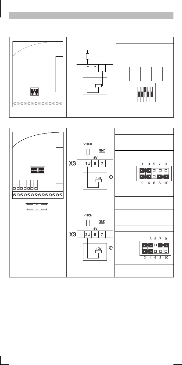
Klemmenbelegung
X3/8:
>100k
GND1
+5V
8 9
3
7
10k
weißer Draht
X3/9:
grüner Draht
X3/7:
brauner Draht
Schalterstellung
1 2 3 4 5
OFF OFF ON OFF OFF
E82ZAFS010
Parametrierung C0034
Poti-Einheit C0034 = -0-
Verdrahtung Eingang 1U
X3/1U:
X3/9:
X3/7:
Jumperstellung
Jumper A
entfernen
E82ZAFA011
Parametrierung C0034
C0034/1 = -0-
Verdrahtung Eingang 2U
X3/2U:
X3/9:
X3/7:
Jumperstellung
Jumper B
entfernen
ON
1 2 3 4 5
weißer Draht
grüner Draht
brauner Draht
weißer Draht
grüner Draht
brauner Draht
E82ZDET001
E82ZDET001
l
E82ZAFA012
Parametrierung C0034
Poti-Einheit C0034/2 = -0-
-3-
E82ZDET001
EDK82ZBX020 3.0
Page 4

Schalter-Einheit — Installation
Show/Hide Bookmarks
Schalter-Einheit installieren und anschließen
1. Am Trägergehäuse Einbau-Öffnung M20 freibrechen oder Verschlusskappe entfernen.
2. Schalter-Einheit von außen in die Einbau-Öffnung einschrauben.
- Schutzart IP55 bleibt durch vormontierten Dichtring erhalten.
3. Aufkleber auf das Trägergehäuse kleben.
4. Schalter-Einheit an das Funktionsmodul anschließen.
5. Bei Funktionsmodulen mit Klemmen X3/7 und X3/39:
- Drahtbrücke zwischen X3/7 und X3/39 legen.
6. Ggf. Antriebsregler parametrieren.
l
-4-
EDK82ZBX020 3.0
Page 5
Schalter-Einheit — Installation
CWRech
tslauf
grünerDraht=unbenutzt
Show/Hide Bookmarks
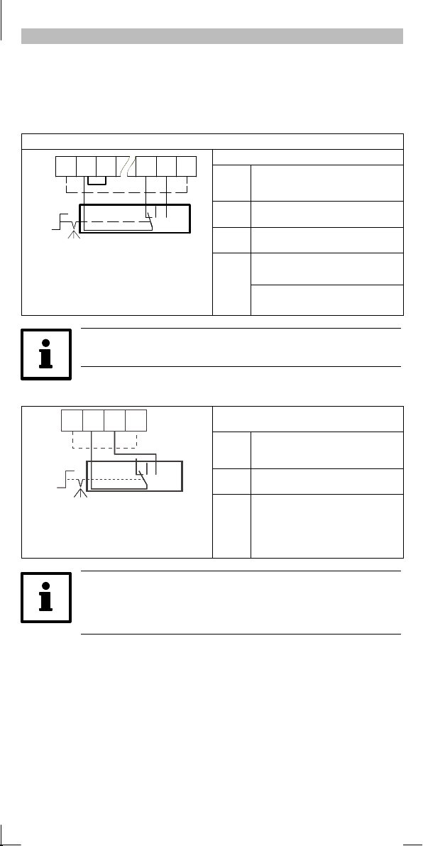
Anwendungsbeispiele 8200 motec:
Drehrichtungsumkehr (Links - Stop - Rechts) mit Standard-I/O oder Application-I/O
Der Ablauf nach dem Ausschalten (STOP) erfolgt an der QSP-Rampe (C0105).
Der Ablauf und Hochlauf nach dem Umschalten der Drehrichtung erfolgt an den Rampen C0013
und C0012.
Beispiel für Klemmenkonfiguration C0007 = -16-
28 E3E2 E4 39207X3
CW CCW0
CW CCW0
E82ZBSP001
Schalter-Einheit
Brücke nur bei Standard-I/O
0Stop
CCW Linkslauf
Mit C0410 könen Sie die Klemmenkonfiguration frei parametrieren (siehe
Betriebsanleitung)
Starten/Stoppen (CINH) mit beliebigem Funktionsmodul
28 39207X3
28 39207X3
28 39207X3
28 39207X3
STOP
STOP
STOP
STOP
START
START
START
START
0
0
0
0
STARTSTOP
0
STARTSTOP
0
STARTSTOP
0
STARTSTOP
0
Schalter-Einheit
STOP Regler gesperrt
0 Regler gesperrt
START Regler freigegeben
E82ZBSP002
Klemmenbelegung
X3/20 brauner Draht
DC-Versorgung +20 V
Drahtbrücke zu X3/28 (CINH)
X3/E3 weißer Draht = Rechtslauf
(CW/QSP an X3/E3)
X3/E4 grüner Draht = Linkslauf
(CCW/QSP an X3/E4)
Parametrierung C0007
Klemmenbelegung
X3/20 brauner Draht
DC-Versorgung +20 V
X3/28 weißer Draht = CINH
grüner Draht = unbenutzt
Geeignet isolieren!
C0007 = -16-
l
• Sie können statt X3/28 auch einen Digitaleingang (X3/E1 ... X3/E6)
ansteuern und damit andere dig itale Funkt ionen akt ivieren (nur
Stand ard- I/O oder Applicatio n- I/O).
• Z. B. Festfrequenz JOG1 an E1.
-5-
EDK82ZBX020 3.0
Page 6
Schalter-Einheit — Installation
r
ünerDrah
t
t
Show/Hide Bookmarks
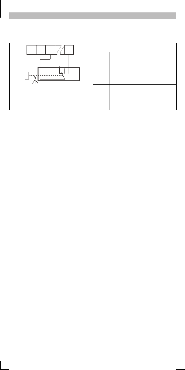
Anwendungsbeispiel starttec:
Starten/Stoppen
28
207X3
28
207X3
28
207X3
28
207X3
STOP
STOP
STOP
STOP
STOP
STOP
STOP
STOP
START
0
START
0
START
0
START
Schalter-Einheit
STOP Motor steht
0 Motor steht
START Motor dreht
0
0
0
0
0
E1
E1
E1
E1
START
START
START
START
E82ZBSP003
Klemmenbelegung
X3/20 brauner Draht
DC-Versorgung +20 V
Drahtbrücke zu X3/28 = starttec
freigegeben
X3/E1 weißer Draht = starttec aktiv / inaktiv
g
=unbenutz
Geeignet isolieren!
l
-6-
EDK82ZBX020 3.0
Page 7

EDK82ZBX020
Show/Hide Bookmarks
00454680
Mounting Instructions
Potentiometer E82ZBR020
06/02
Switch unit E82ZBS020
These Instructions
describe the installation and handling of the potentiometer unit and switch unit.
are only valid
- for potentiometer units with the designation E82ZBR020.
- for switch units with the designa tion E82ZBS020.
- together with the Operating Instructions of the corresponding controller.
Description
The potentiometer unit E82ZBR020 allows the selection of an analog setpoint signal for Lenze
controllers through the function modules Standard I/O or Application I/O.
The switch unit allows straightforward control of Lenze controllers through digital inputs of the
function modules Standard I/O or Application I/O (e. g. reversal of direction of rotation).
Range of application
Canbeusedwith
Frequency inverters 8200 motec
Motor starters starttec
Items supplied
Potentiometer unit Switch unit
1 Potentiometer unit mounted completely, 10 k Ω 1 switch unit, mounted completely
1 sticker for potentiometer settings 1 sticker for switch settings
General data and application conditions
Enclosure IP55
Dimensions [mm]
Possible mounting p ositions
The unit is mounted with an M20 bore.
Lenze Drive Systems GmbH, Postfach 10 13 52, D-31763 Hameln
l
( (+49) 5154 82-0, Fax Service: (+49) 5154 82-1112
E82ZBX001
EDK82ZBX020 3.0
Page 8

Potentiometer unit - Installation
Show/Hide Bookmarks
Install and connect potentiometer unit
1. Break free opening M20 at the carrier housing or remove cover.
2. Bolt potentiometer unit into the opening from outside.
- Enclosure IP55 is maintained thanks to the preassembled seal.
3. Fix sticker to the carrier housing.
4. Connect potentiometer unit to the function module.
5. Configure hardware and software of the motec for a setpoint range of 0 ... 5 V:
- Adapt the switch/jumper position at the function module.
- Adapt C0034.
l
-2-
EDK82ZBX020 3.0
Page 9

Potentiometer unit - Installation
X
E82ZAFA01
1
Show/Hide Bookmarks
Connection at the Standard I/O
STANDARD S
STANDARD S
STANDARD S
STANDARD S
STANDARD S
STANDARD S
STANDARD S
STANDARD S
ON
ON
ON
ON
ON
ON
ON
ON
1 2 3 4 5
1 2 3 4 5
1 2 3 4 5
1 2 3 4 5
1 2 3 4 5
1 2 3 4 5
1 2 3 4 5
1 2 3 4 5
A139
A139
A139
A139
A139
A139
A139
762 8 9720 28 E1 59E2E3E4
762 8 9720 28 E1 59E2E3E4
762 8 9720 28 E1 59E2E3E4
762 8 9720 28 E1 59E2E3E4
762 8 9720 28 E1 59E2E3E4
762 8 9720 28 E1 59E2E3E4
762 8 9720 28 E1 59E2E3E4
762 8 9720 28 E1 59E2E3E4
Connection at the Application I/O
APPLICATION A
APPLICATION A
APPLICATION A
APPLICATION A
APPLICATION A
APPLICATION A
APPLICATION A
APPLICATION A
APPLICATION A
APPLICATION A
APPLICATION A
APPLICATION A
5
5
5
5
5
5
5
5
5
5
5
5
3
3
3
3
3
3
3
3
3
3
3
3
6
6
6
6
6
6
6
6
6
6
6
6
214
214
214
214
214
214
214
214
214
214
214
214
1U 1I
1U 1I
1U 1I
1U 1I
1U 1I
1U 1I
1U 1I
1U 1I
1U 1I
1U 1I
1U 1I
1U 1I
2U
2U
2U
2U
2U
2U
2U
2U
2U
2U
2U
2U
62
62
62
62
62
62
62
62
62
62
62
62
2I
2I
2I
2I
2I
2I
2I
2I
2I
2I
2I
2I
63 9
63 9
63 9
63 9
63 9
63 9
63 9
63 9
63 9
63 9
63 9
63 9
A2A1 7 7A459 20 28 E1E2E3 E4
A2A1 7 7A459 20 28 E1E2E3 E4
A2A1 7 7A459 20 28 E1E2E3 E4
A2A1 7 7A459 20 28 E1E2E3 E4
A2A1 7 7A459 20 28 E1E2E3 E4
A2A1 7 7A459 20 28 E1E2E3 E4
A2A1 7 7A459 20 28 E1E2E3 E4
A2A1 7 7A459 20 28 E1E2E3 E4
A2A1 7 7A459 20 28 E1E2E3 E4
A2A1 7 7A459 20 28 E1E2E3 E4
A2A1 7 7A459 20 28 E1E2E3 E4
A2A1 7 7A459 20 28 E1E2E3 E4
1
1
1
1
1
1
1
1
1
1
1
1
3
3
3
3
3
3
3
3
3
3
3
3
C
C
C
C
C
C
C
C
C
C
C
C
D
D
D
D
D
D
D
D
D
D
D
D
2
2
2
2
2
2
2
2
2
2
2
2
45678910
45678910
45678910
45678910
45678910
45678910
45678910
45678910
45678910
45678910
45678910
45678910
A139
E82ZAFS001
Potentiometer unit C0034 = -0-
7
7
7
7
7
7
7
7
7
7
7
7
1098
1098
1098
1098
1098
1098
1098
1098
1098
1098
1098
1098
E5 E6
E5 E6
E5 E6
E5 E6
E5 E6
E5 E6
E5 E6
E5 E6
E5 E6
E5 E6
E5 E6
E5 E6
A
A
A
A
A
A
A
A
A
A
A
A
B
B
B
B
B
B
B
B
B
B
B
B
E82ZAFA004
Terminal assignment
X3/8:
>100k
GND1
+5V
8 9
3
7
10k
White wire
X3/9:
Green wire
X3/7:
Brown wire
Switch position
1 2 3 4 5
OFF OFF ON OFF OFF
ON
E82ZAFS010
E82ZAFA011
1 2 3 4 5
Parameterization C0034
Wiring input 1U
X3/1U:
X3/9:
X3/7:
White wire
Green wire
Brown wire
Jumper position
Remove
jumper A
Parameterization C0034
C0034/1 = -0-
Wiring input 2U
X3/2U:
X3/9:
X3/7:
White wire
Green wire
Brown wire
Jumper position
Remove
jumper B
E82ZDET001
E82ZDET001
l
E82ZAFA012
Parameterization C0034
Potentiometer unit C0034/2 = -0-
-3-
E82ZDET001
EDK82ZBX020 3.0
Page 10

Switch unit - Installation
Show/Hide Bookmarks
Install and connect switch unit
1. Break free opening M20 at the carrier housing or remove cover.
2. Bolt switch unit into the opening from outside.
- Enclosure IP55 is maintained thanks to the preassembled seal.
3. Fix sticker to the carrier housing.
4. Connect switch unit to the function module.
5. For function modules with terminals X3/7 and X3/39:
- Connect X3/7 and X3/39 using a jumper.
6. Parameterize controller, if necessary.
l
-4-
EDK82ZBX020 3.0
Page 11

Switch unit - Installation
CWCWrotat
i
Greenwire=notused
Show/Hide Bookmarks
Application examples 8200 motec:
Reversal of direction of rotation (CCW - Stop - CW) with Standard I/O or
Application I/O
Deceleration after STOP along the quick stop ramp (C0105).
Deceleration and acceleration after a reversal of the direction of rotation along ramps C0013 and
C0012.
Example for terminal configuration C0007 = -16-
28 E3E2 E4 39207X3
CW CCW0
CW CCW0
E82ZBSP001
Switch unit
Jumper only for Standard I/O
on
0Stop
CCW CCW rotation
You can parameterise the terminal c onfiguration using C0410 as desired
(see Operating Instructions)
Start/Stop (CINH) with any function module
28 39207X3
28 39207X3
28 39207X3
28 39207X3
STOP
STOP
STOP
STOP
START
START
START
START
0
0
0
0
STARTSTOP
0
STARTSTOP
0
STARTSTOP
0
STARTSTOP
0
Switch unit
STOP Controller inhibited
0 Controller inhibited
START Controller enabled
E82ZBSP002
Terminal assignment
X3/20 Brown wire
DC supply +20 V
Jumper to X3/28 (CINH)
X3/E3 White wire = CW rotation
(CW/QSP on X3/E3)
X3/E4 Green wire = CCW rotation
(CCW/QSP on X3/E4)
Parameterisation C0007
Terminal assignment
X3/20 Brown wire
DC supply +20 V
X3/28 White wire = CINH
Green wire = not used
Appropriate insulation!
C0007 = -16-
l
• Instead of using X3/28 digital input, (X3/E1 ... X3/E6) can also be
connect ed and t hus d iff erent dig ital functions (e.g. fixed frequency
JOG1 at E1) can be activated .
• For inst ance, fix ed frequency J OG1 at E1.
-5-
EDK82ZBX020 3.0
Page 12

Switch unit - Installation
Greenwire=notused
Show/Hide Bookmarks
Application example starttec:
Start/Stop
28
207X3
28
207X3
28
207X3
28
207X3
STOP
STOP
STOP
STOP
STOP
STOP
STOP
STOP
START
0
START
0
START
0
START
Switch unit
STOP Motor not rotating
0 Motor not rotating
START Motor rotating
0
0
0
0
0
E1
E1
E1
E1
START
START
START
START
E82ZBSP003
Terminal assignment
X3/20 Brown wire
DC supply +20 V
Jumper to X3/28 = starttec enabled
X3/E1 White wire = starttec active / inactive
Green wire=notused
Appropriate insulation!
l
-6-
EDK82ZBX020 3.0
Page 13

EDK82ZBX020
Show/Hide Bookmarks
00454680
Instructions de montage
Unité potentiomètre E82ZBR020
06/02
Unité interrupteur E82ZBS020
Le présent fascicule
décrit l’installation et la manipulation de l’unité potentiomètre et de l’unité interrupteur ;
n’est valable que
- pour les unités potentiomètre type E82ZBR020,
- pour les unités interrupteur type E82ZBS020,
- conjointement avec les instructions de mise en service du variateur de vitesse concerné.
Description
L’unité potentiomètre E82ZBR020 permet l’ entrée d’un signal de consigne analogique pour les
variateurs de vitesse Lenze via les modules de fonction E/S standard ou E/S application.
L’unité interrupteur E82ZBS020 permet une commande simplifiée des variateurs de vitesse Lenze
via des modules de fonction E/S standard ou E/S application (exemple : inversion du sens de
rotation).
Domaine d’utilisation
Utilisation possible sur
les convertisseurs de fréquence 8200 motec,
les démarreurs moteur starttec.
Equipement livré
Unité potentiomètre Unité interrupteur
1 unité potentiomètre précâblée, 10 k Ω 1 unité interrupteur précâblée
1 autocollant pour positions potentiomètre 1 autocollant pour positions interrupteur
Caractéristiques générales et conditions ambiantes
Protection IP55
Encombrements
[mm]
Montages possibles
L’unité est montée avec un alésage M20.
Lenze Drive Systems GmbH, Postfach 10 13 52, D-31763 Hameln
l
( (+49) 5154 82-0, Fax Service: (+49) 5154 82-1112
E82ZBX001
EDK82ZBX020 3.0
Page 14

Unité potentiomètre - Installation
Show/Hide Bookmarks
Installation et raccordement de l’unité potentiomètre
1. Sur l’embase, casser l’orifice de montage M20 ou enlever le capot de protection.
2. Visser l’unité potentiomètre par l’extérieur, dans l’orifice de montage.
- L’indice de protection IP55 est maintenu grâce au joint monté en amont.
3. Coller l’autocollant sur l’embase.
4. Raccorder l’unité potentiomètre au module de fonction.
5. Configurer le matériel et le logiciel du motec pour la plage de consigne 0 ... 5 V :
- Adapter la position de l’interrupteur ou du pont sur le module de fonction.
- Régler C0034.
l
-2-
EDK82ZBX020 3.0
Page 15

Unité potentiomètre - Installation
X
E82ZAFA01
1
Show/Hide Bookmarks
Raccordement sur le module E/S standard
STANDARD S
STANDARD S
STANDARD S
STANDARD S
STANDARD S
STANDARD S
STANDARD S
STANDARD S
ON
ON
ON
ON
ON
ON
ON
ON
1 2 3 4 5
1 2 3 4 5
1 2 3 4 5
1 2 3 4 5
1 2 3 4 5
1 2 3 4 5
1 2 3 4 5
1 2 3 4 5
A139
A139
A139
A139
A139
A139
A139
762 8 9720 28 E1 59E2E3E4
762 8 9720 28 E1 59E2E3E4
762 8 9720 28 E1 59E2E3E4
762 8 9720 28 E1 59E2E3E4
762 8 9720 28 E1 59E2E3E4
762 8 9720 28 E1 59E2E3E4
762 8 9720 28 E1 59E2E3E4
762 8 9720 28 E1 59E2E3E4
A139
E82ZAFS001
Raccordement sur le module E/S application
APPLICATION A
APPLICATION A
APPLICATION A
APPLICATION A
APPLICATION A
APPLICATION A
APPLICATION A
APPLICATION A
APPLICATION A
APPLICATION A
APPLICATION A
APPLICATION A
5
5
5
5
5
5
5
5
5
5
5
5
7
7
7
7
7
7
7
7
7
7
7
7
3
3
3
3
3
3
3
3
3
3
3
3
1098
6
1098
6
1098
6
1098
6
1098
6
1098
6
1098
6
1098
6
1098
6
1098
6
1098
6
1098
6
214
214
214
214
214
214
214
214
214
214
214
214
1U 1I
1U 1I
1U 1I
1U 1I
1U 1I
1U 1I
1U 1I
1U 1I
1U 1I
1U 1I
1U 1I
1U 1I
2U
2U
2U
2U
2U
2U
2U
2U
2U
2U
2U
2U
62
62
62
62
62
62
62
62
62
62
62
62
2I
2I
2I
2I
2I
2I
2I
2I
2I
2I
2I
2I
63 9
63 9
63 9
63 9
63 9
63 9
63 9
63 9
63 9
63 9
63 9
63 9
E5 E6
E5 E6
E5 E6
E5 E6
E5 E6
E5 E6
E5 E6
E5 E6
E5 E6
E5 E6
E5 E6
A
A
A
A
A
A
A
A
A
A
A
A
B
B
B
B
B
B
B
B
B
B
B
B
E5 E6
E82ZAFA004
A2A1 7 7A459 20 28 E1E2E3 E4
A2A1 7 7A459 20 28 E1E2E3 E4
A2A1 7 7A459 20 28 E1E2E3 E4
A2A1 7 7A459 20 28 E1E2E3 E4
A2A1 7 7A459 20 28 E1E2E3 E4
A2A1 7 7A459 20 28 E1E2E3 E4
A2A1 7 7A459 20 28 E1E2E3 E4
A2A1 7 7A459 20 28 E1E2E3 E4
A2A1 7 7A459 20 28 E1E2E3 E4
A2A1 7 7A459 20 28 E1E2E3 E4
A2A1 7 7A459 20 28 E1E2E3 E4
A2A1 7 7A459 20 28 E1E2E3 E4
1
1
1
1
1
1
1
1
1
1
1
1
3
3
3
3
3
3
3
3
3
3
3
3
C
C
C
C
C
C
C
C
C
C
C
C
D
D
D
D
D
D
D
D
D
D
D
D
2
2
2
2
2
2
2
2
2
2
2
2
45678910
45678910
45678910
45678910
45678910
45678910
45678910
45678910
45678910
45678910
45678910
45678910
>100k
8 9
3
Unité potentiomètre C0034 = -0-
GND1
+5V
10k
E82ZAFA011
7
E82ZAFS010
Affectation des bornes
X3/8 :
Fil blanc
X3/9 :
Fil vert
X3/7 :
Fil marron
Position interrupteur
1 2 3 4 5
OFF OFF ON OFF OFF
ON
1 2 3 4 5
E82ZDET001
Paramétrage C0034
Câblage entrée 1U
X3/1U :
X3/9 :
X3/7 :
Fil blanc
Fil vert
Fil marron
Position du pont
Enlever le
pont A.
Paramétrage C0034
E82ZDET001
C0034/1 = -0-
Câblage entrée 2U
X3/2U :
X3/9 :
X3/7 :
Fil blanc
Fil vert
Fil marron
Position du pont
Enlever le
pont B.
l
E82ZAFA012
Paramétrage C0034
Unité potentiomètre C0034/2 = -0-
-3-
E82ZDET001
EDK82ZBX020 3.0
Page 16

Unité interrupteur - Installation
Show/Hide Bookmarks
Installation et raccordement de l’unité interrupteur
1. Sur l’embase, casser l’orifice de montage M20 ou enlever le capot de protection.
2. Visser l’unité interrupteur par l’extérieur, dans l’orifice de montage.
- L’indice de protection IP55 est maintenu grâce au joint monté en amont.
3. Coller l’autocollant sur l’embase.
4. Raccorder l’unité interrupteur au module de fonction.
5. Pour les modules de fonction avec bornes X3/7 et X3/39 :
- Etablir un pont entre X3/7 et X3/39.
6. Le cas échéant, paramétrer le variateur.
l
-4-
EDK82ZBX020 3.0
Page 17

Unité interrupteur - Installation
CWS
i
r
Filvert=Nonutilis
é
Show/Hide Bookmarks
Exemples d’application 8200 motec :
Inversion du sens de rotation (sens antihoraire - stop - sens horaire) avec E/S
standard ou E/S application
Après la coupure (STOP), la décélération s’effectue selon la rampe d’arrêt rapide (C0105).
Après inversion du sens de rotation, la décélération et l’accélération s’effectuent selon les rampes
C0013 et C0012.
Exemple : Configuration des bornes C0007 = -16-
28 E3E2 E4 39207X3
CW CCW0
CW CCW0
E82ZBSP001
Unité interrupteur
Pont uniquement pour E/S standard
enshora
e
0 ARRET
CCW Sens antihoraire
Le code C0410 vous permet de configurer les bornes (voir instruct ions de
mise en service).
Marche/arrêt(CINH)avecmoduledefonction
28 39207X3
28 39207X3
28 39207X3
28 39207X3
STOP
STOP
STOP
STOP
START
START
START
START
0
0
0
0
STARTSTOP
0
STARTSTOP
0
STARTSTOP
0
STARTSTOP
0
Unité interrupteur
STOP Blocage variateur
0Blocagevariateur
START Déblocage variateur
E82ZBSP002
Affectation des bornes
X3/20 Fil marron
Alimentation CC +20 V
Pont vers X3/28 (CINH)
X3/E3 Fil blanc = Sens horaire
(CW (H)/QSP (AR) sur X3/E3)
X3/E4 Fil vert = Sens antihoraire
(CCW (AH)/QSP (AR) sur X3/E4)
Paramétrage C0007
Affectation des bornes
X3/20 Fil marron
Alimentation CC +20 V
X3/28 Fil blanc = CINH
Fil vert = Non utilisé
Prévoir une isolation appropriée !
C0007 = -16-
l
• Il est également possible d’act iver une entrée numérique (X3/E1 ...
X3/ E6) à laplacedeX3/28etd’activer ainsi d’autres fonc tions
numériques (E/S standard ou E/S app lic ation uniquement ).
• Exemp le : Fréquence fixe JOG1 sur E1.
-5-
EDK82ZBX020 3.0
Page 18

Unité interrupteur - Installation
Filvert=Nonutilis
é
Show/Hide Bookmarks
Exemple d’application starttec :
Marche/arrêt
28
207X3
28
207X3
28
207X3
28
207X3
STOP
STOP
STOP
STOP
START
0
START
0
START
0
START
Unité interrupteur
STOP Le moteur est arrêté.
0 Le moteur est arrêté.
START Le moteur tourne.
0
STOP
STOP
STOP
STOP
0
0
0
0
E1
E1
E1
E1
START
START
START
START
E82ZBSP003
Affectation des bornes
X3/20 Fil marron
Alimentation CC +20 V
Pont vers X3/28 = starttec débloqué
X3/E1 Fil blanc = starttec actif/inactif
Fil vert = Non utilisé
Prévoir une isolation appropriée !
l
-6-
EDK82ZBX020 3.0
 Loading...