

Page 1
EDS82ZAFVCxxx
.IFõ
Ä.IFõä
L−force Communication
Communication Manual
DeviceNet
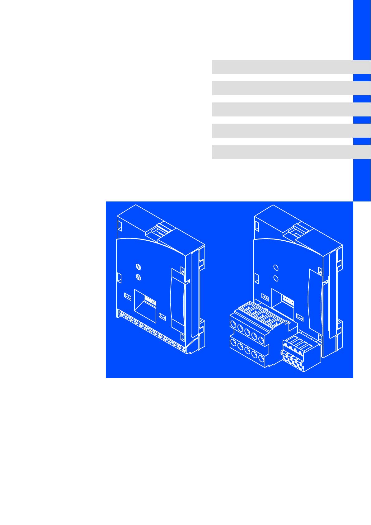
E82ZAFVC001 / E82ZAFVC010
Function module
l
Page 2

Contentsi
1 About this documentation 4 . . . . . . . . . . . . . . . . . . . . . . . . . . . . . . . . . . . . . . . . . . . . . . . . . .
1.1 Document history 5 . . . . . . . . . . . . . . . . . . . . . . . . . . . . . . . . . . . . . . . . . . . . . . . . . . . .
1.2 Conventions used 6 . . . . . . . . . . . . . . . . . . . . . . . . . . . . . . . . . . . . . . . . . . . . . . . . . . . .
1.3 Terminology used 6 . . . . . . . . . . . . . . . . . . . . . . . . . . . . . . . . . . . . . . . . . . . . . . . . . . . .
1.4 Notes used 7 . . . . . . . . . . . . . . . . . . . . . . . . . . . . . . . . . . . . . . . . . . . . . . . . . . . . . . . . . .
2 Safety instructions 8 . . . . . . . . . . . . . . . . . . . . . . . . . . . . . . . . . . . . . . . . . . . . . . . . . . . . . . . . .
2.1 General safety information 8 . . . . . . . . . . . . . . . . . . . . . . . . . . . . . . . . . . . . . . . . . . . .
2.2 Device− and application−specific safety instructions 9 . . . . . . . . . . . . . . . . . . . . . . . .
2.3 Residual hazards 9 . . . . . . . . . . . . . . . . . . . . . . . . . . . . . . . . . . . . . . . . . . . . . . . . . . . . .
3 Product description 10 . . . . . . . . . . . . . . . . . . . . . . . . . . . . . . . . . . . . . . . . . . . . . . . . . . . . . . . .
3.1 Application as directed 10 . . . . . . . . . . . . . . . . . . . . . . . . . . . . . . . . . . . . . . . . . . . . . . .
3.2 Identification 11 . . . . . . . . . . . . . . . . . . . . . . . . . . . . . . . . . . . . . . . . . . . . . . . . . . . . . . . .
3.3 Product features 12 . . . . . . . . . . . . . . . . . . . . . . . . . . . . . . . . . . . . . . . . . . . . . . . . . . . . .
3.4 Connections and interfaces 13 . . . . . . . . . . . . . . . . . . . . . . . . . . . . . . . . . . . . . . . . . . . .
4 Technical data 15 . . . . . . . . . . . . . . . . . . . . . . . . . . . . . . . . . . . . . . . . . . . . . . . . . . . . . . . . . . . .
4.1 General data 15 . . . . . . . . . . . . . . . . . . . . . . . . . . . . . . . . . . . . . . . . . . . . . . . . . . . . . . . .
4.2 Operating conditions 15 . . . . . . . . . . . . . . . . . . . . . . . . . . . . . . . . . . . . . . . . . . . . . . . . .
4.3 Protective insulation 16 . . . . . . . . . . . . . . . . . . . . . . . . . . . . . . . . . . . . . . . . . . . . . . . . . .
4.4 Connection terminals 17 . . . . . . . . . . . . . . . . . . . . . . . . . . . . . . . . . . . . . . . . . . . . . . . . .
4.5 Communication time 18 . . . . . . . . . . . . . . . . . . . . . . . . . . . . . . . . . . . . . . . . . . . . . . . . .
4.6 Dimensions 19 . . . . . . . . . . . . . . . . . . . . . . . . . . . . . . . . . . . . . . . . . . . . . . . . . . . . . . . . . .
5 Installation 20 . . . . . . . . . . . . . . . . . . . . . . . . . . . . . . . . . . . . . . . . . . . . . . . . . . . . . . . . . . . . . . .
5.1 Mechanical installation 20 . . . . . . . . . . . . . . . . . . . . . . . . . . . . . . . . . . . . . . . . . . . . . . . .
5.2 Electrical installation 20 . . . . . . . . . . . . . . . . . . . . . . . . . . . . . . . . . . . . . . . . . . . . . . . . . .
5.2.1 Wiring according to EMC (CE−typical drive system) 20 . . . . . . . . . . . . . . . . .
5.2.2 Wiring with a host (master) 21 . . . . . . . . . . . . . . . . . . . . . . . . . . . . . . . . . . . .
5.2.3 Voltage supply 24 . . . . . . . . . . . . . . . . . . . . . . . . . . . . . . . . . . . . . . . . . . . . . .
5.2.4 Terminal assignment 25 . . . . . . . . . . . . . . . . . . . . . . . . . . . . . . . . . . . . . . . . .
5.2.5 Cable cross−sections and screw−tightening torques 27 . . . . . . . . . . . . . . . . .
5.2.6 Bus cable length 28 . . . . . . . . . . . . . . . . . . . . . . . . . . . . . . . . . . . . . . . . . . . .
5.2.7 Use of plug connectors 28 . . . . . . . . . . . . . . . . . . . . . . . . . . . . . . . . . . . . . . . .
6 Commissioning 29 . . . . . . . . . . . . . . . . . . . . . . . . . . . . . . . . . . . . . . . . . . . . . . . . . . . . . . . . . . .
6.1 Before switching on 29 . . . . . . . . . . . . . . . . . . . . . . . . . . . . . . . . . . . . . . . . . . . . . . . . . .
6.2 Commissioning steps 29 . . . . . . . . . . . . . . . . . . . . . . . . . . . . . . . . . . . . . . . . . . . . . . . . .
6.3 Controls and displays 31 . . . . . . . . . . . . . . . . . . . . . . . . . . . . . . . . . . . . . . . . . . . . . . . . .
6.3.1 Possible settings using the front switch 31 . . . . . . . . . . . . . . . . . . . . . . . . . .
l 2
EDS82ZAFVCxxx EN 4.0
Page 3

Contents i
7 Diagnostics 34 . . . . . . . . . . . . . . . . . . . . . . . . . . . . . . . . . . . . . . . . . . . . . . . . . . . . . . . . . . . . . . .
7.1 LED status displays 34 . . . . . . . . . . . . . . . . . . . . . . . . . . . . . . . . . . . . . . . . . . . . . . . . . .
7.2 Troubleshooting and fault elimination 36 . . . . . . . . . . . . . . . . . . . . . . . . . . . . . . . . . . .
8 Codes 37 . . . . . . . . . . . . . . . . . . . . . . . . . . . . . . . . . . . . . . . . . . . . . . . . . . . . . . . . . . . . . . . . . . . .
9 Appendix 53 . . . . . . . . . . . . . . . . . . . . . . . . . . . . . . . . . . . . . . . . . . . . . . . . . . . . . . . . . . . . . . . .
9.1 Data transfer 53 . . . . . . . . . . . . . . . . . . . . . . . . . . . . . . . . . . . . . . . . . . . . . . . . . . . . . . . .
9.1.1 Overview of the implemented objects for the function module 55 . . . . . . .
10 Index 66 . . . . . . . . . . . . . . . . . . . . . . . . . . . . . . . . . . . . . . . . . . . . . . . . . . . . . . . . . . . . . . . . . . . .
EDS82ZAFVCxxx EN 4.0
l 3
Page 4

About this documentation1
0Fig. 0Tab. 0
1 About this documentation
Contents
This documentation exclusively contains descriptions regarding the E82ZAFVC001
(DeviceNet) and E82ZAFVC010 (DeviceNet PT) function modules.
) Note!
This documentation supplements the mounting instructions supplied with the
function module and the documentation for the standard devices used.
The mounting instructions contain safety instructions which must be
observed!
ƒ The features and functions of the function module are described in detail.
ƒ Typical applications are explained by means of examples.
ƒ Moreover, this documentation contains the following:
– Safety instructions which must be observed.
– The essential technical data of the function module
– Information on versions of the Lenze standard devices to be used
– Notes on troubleshooting and fault elimination
The theoretical concepts are only explained to the level of detail required to understand
the function of the function module.
Depending on the software version of the controller and the version of the »Engineer«
software installed, the screenshots in this documentation may deviate from the
»Engineer« representation.
This documentation does not describe any software provided by other manufacturers. No
liability can be accepted for corresponding data provided in this documentation. For
information on how to use the software, please refer to the host system (master)
documents.
All brand names mentioned in this documentation are trademarks of their respective
owners.
Validity information
The information given in this documentation is valid for the following devices:
Function module Type designation from hardware version from software version
DeviceNet E82ZAFVC001 Vx 0x
DeviceNet PT E82ZAFVC010 Vx 0x
4
l
EDS82ZAFVCxxx EN 4.0
Page 5

Target group
This documentation is intended for all persons who plan, install, commission and maintain
the networking and remote service of a machine.
I Tip!
Information and auxiliary devices related to the Lenze products can be found
in the download area at
http://www.Lenze.com
1.1 Document history
Material no. Version Description
− 1.0 06/2004 TD06 First edition
.IFõ 4.0 03/2012 TD29 General revision
About this documentation
Document history
1
Your opinion is important to us!
These instructions were created to the best of our knowledge and belief to give you the
best possible support for handling our product.
If you have suggestions for improvement, please e−mail us to:
feedback−docu@Lenze.de
Thank you for your support.
Your Lenze documentation team
EDS82ZAFVCxxx EN 4.0
l
5
Page 6

1
About this documentation
Conventions used
1.2 Conventions used
This documentation uses the following conventions to distinguish between different
types of information:
Type of information Identification Examples/notes
Spelling of numbers
Decimal separator
Decimal Standard notation For example: 1234
Hexadecimal 0x[0 ... 9, A ... F] For example: 0x60F4
Binary
l Nibble
Text
Program name » « PC software
Icons
Page reference ^ Reference to another page with additional
Point In general, the decimal point is used.
For instance: 1234.56
In quotation marks
Point
For example: ´100´
For example: ´0110.0100´
For example: »Engineer«, »Global Drive
Control« (GDC)
information
For instance: ^ 16 = see page 16
1.3 Terminology used
Term Meaning
PROFIBUS The term stands for the PROFIBUS−DP variant according to IEC 61158/IEC 61784. A
Standard device
Controller
Frequency inverter
Master PROFIBUS station which takes over the master function in the fieldbus system.
Slave PROFIBUS station which acts as a slave in the fieldbus system.
Code "Container" for one or more parameters which can be used to parameterise or
Subcode If a code contains more than one parameter, these parameters are stored in
POW Process output data word
PIW Process input data word
different PROFIBUS variant is not described in this manual.
Lenze controllers/frequency inverters for which the function module can be used.
^ 10
monitor the controller.
"subcodes".
In this documentation, a slash "/" is used as a separator when specifying a code and
its subcode (e.g. "C00118/3").
6
l
EDS82ZAFVCxxx EN 4.0
Page 7

1.4 Notes used
The following pictographs and signal words are used in this documentation to indicate
dangers and important information:
Safety instructions
Structure of safety instructions:
} Danger!
(characterises the type and severity of danger)
Note
(describes the danger and gives information about how to prevent dangerous
situations)
Pictograph and signal word Meaning
{ Danger!
} Danger!
( Stop!
About this documentation
Notes used
Danger of personal injury through dangerous electrical voltage.
Reference to an imminent danger that may result in death or
serious personal injury if the corresponding measures are not
taken.
Danger of personal injury through a general source of danger.
Reference to an imminent danger that may result in death or
serious personal injury if the corresponding measures are not
taken.
Danger of property damage.
Reference to a possible danger that may result in property
damage if the corresponding measures are not taken.
1
Application notes
Pictograph and signal word Meaning
) Note!
I Tip!
,
Important note to ensure troublefree operation
Useful tip for simple handling
Reference to another documentation
EDS82ZAFVCxxx EN 4.0
l
7
Page 8

2
Safety instructions
General safety information
2 Safety instructions
) Note!
It is absolutely vital that the stated safety measures are implemented in order
to prevent serious injury to persons and damage to material assets.
Always keep this documentation to hand in the vicinity of the product during
operation.
2.1 General safety information
} Danger!
Disregarding the following basic safety measures may lead to severe personal
injury and damage to material assets!
ƒ Lenze drive and automation components ...
... must only be used for the intended purpose.
... must never be operated if damaged.
... must never be subjected to technical modifications.
... must never be operated unless completely assembled.
... must never be operated without the covers/guards.
... can − depending on their degree of protection − have live, movable or rotating parts
during or after operation. Surfaces can be hot.
ƒ All specifications of the corresponding enclosed documentation must be observed.
This is vital for a safe and trouble−free operation and for achieving the specified product
features.
The procedural notes and circuit details provided in this document are proposals which
the user must check for suitability for his application. The manufacturer does not
accept any liability for the suitability of the specified procedures and circuit proposals.
ƒ Only qualified skilled personnel are permitted to work with or on Lenze drive and
automation components.
According to IEC 60364 or CENELEC HD 384, these are persons ...
... who are familiar with the installation, assembly, commissioning and operation of
the product,
... possess the appropriate qualifications for their work,
... and are acquainted with and can apply all the accident prevent regulations, directives
and laws applicable at the place of use.
8
l
EDS82ZAFVCxxx EN 4.0
Page 9

Device− and application−specific safety instructions
2.2 Device− and application−specific safety instructions
ƒ During operation, the function module must be firmly connected to the standard
device.
ƒ With external voltage supply, always use a separate power supply unit, safely
separated to EN 61800−5−1 ("SELV"/"PELV"), in every control cabinet.
ƒ Only use cables corresponding to the given specifications (¶ 21).
, Documentation for the standard device, control system, system/machine
All other measures prescribed in this documentation must also be
implemented. Observe the safety instructions and application notes stated in
the documentation.
2.3 Residual hazards
Safety instructions
2
Protection of persons
ƒ If the controllers are used on a phase earthed mains with a rated mains voltage
³ 400 V, protection against accidental contact is not ensured without implementing
external measures. (See chapter "4.3", ^ 16)
Device protection
ƒ The module contains electronic components that can be damaged or destroyed by
electrostatic discharge.
EDS82ZAFVCxxx EN 4.0
l
9
Page 10

3
Product description
Application as directed
3 Product description
3.1 Application as directed
The E82ZAFVC001 function module ...
ƒ is an accessory module for use in conjunction with the following Lenze standard
devices:
Product range Device designation from hardware version
Frequency inverter 8200 vector Vx14
Motor starter starttec Vx1x
ƒ is a device intended for use in industrial power systems.
Any other use shall be deemed inappropriate!
8200 motec Vx14
The E82ZAFVC010 function module ...
ƒ is an accessory module for use in conjunction with the following Lenze standard
devices:
Product range Device designation from hardware version
Frequency inverter 8200 vector Vx14
ƒ is a device intended for use in industrial power systems.
Any other use shall be deemed inappropriate!
10
l
EDS82ZAFVCxxx EN 4.0
Page 11
Product description
APPLICATION
010 / 3A22
Identification
3
3.2 Identification
APPLICATION
010/ 3A22
Product range
DeviceNet
Generation
Variant:
001: Coated design
010: PT design
Hardware version
Software version
L
Type
Id.-No.
Prod.-No.
Ser.-No.
E82AF000P0B201XX
E82ZAFX005
E82ZAF V C 0xx Vx 0x
EDS82ZAFVCxxx EN 4.0
l
11
Page 12

3
3.3 Product features
Product description
Product features
The E82ZAFVC0xx function module (DeviceNet / DeviceNet PT) connects the basic device
to the serial communication system DeviceNet.
Basic devices can be retrofitted.
The function module adds functions to the controller, e.g.
ƒ Parameter selection/remote parameter setting
ƒ Connection to external controls and hosts
The function module is provided with a DIP switch. This DIP switch serves to set the
following:
ƒ Address
ƒ Baud rate
ƒ Compatibility to the Lenze E82ZAFD000Vx04 function module
Besides using the DIP switch, the device address and baud rate can also be set via software.
In this mode, the function module can either automatically or manually detect the baud
rate.
The function module must always be supplied externally.
12
l
EDS82ZAFVCxxx EN 4.0
Page 13
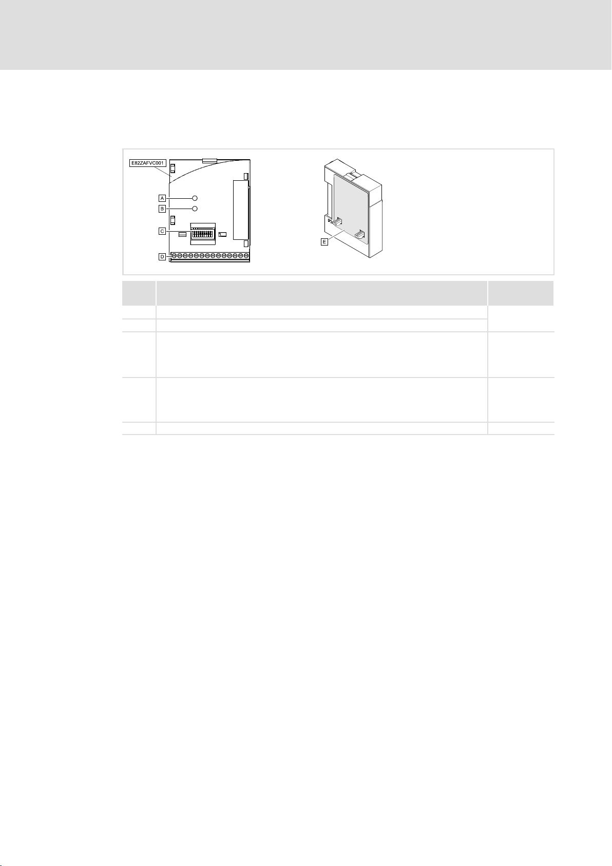
3.4 Connections and interfaces
Function module E82ZAFVC001
Product description
Connections and interfaces
3
E82ZAFV001E
Pos. Description Detailed
0
1
2
3
4
Status display (two−colour green / red), connection to the standard device
Status display (two−colour green / red), connection to the bus
DIP switches for setting
l Node address ("Address")
l Baud rate ("Bd")
l Compatibility with Lenze function module E82ZAFD (DeviceNet)
Terminal strip X3, connections for
l DeviceNet
l Controller inhibit (CINH)
l External voltage supply (via DeviceNet cable)
Nameplate ^ 11
information
^ 34
^ 31
^ 25
EDS82ZAFVCxxx EN 4.0
l
13
Page 14
3
Product description
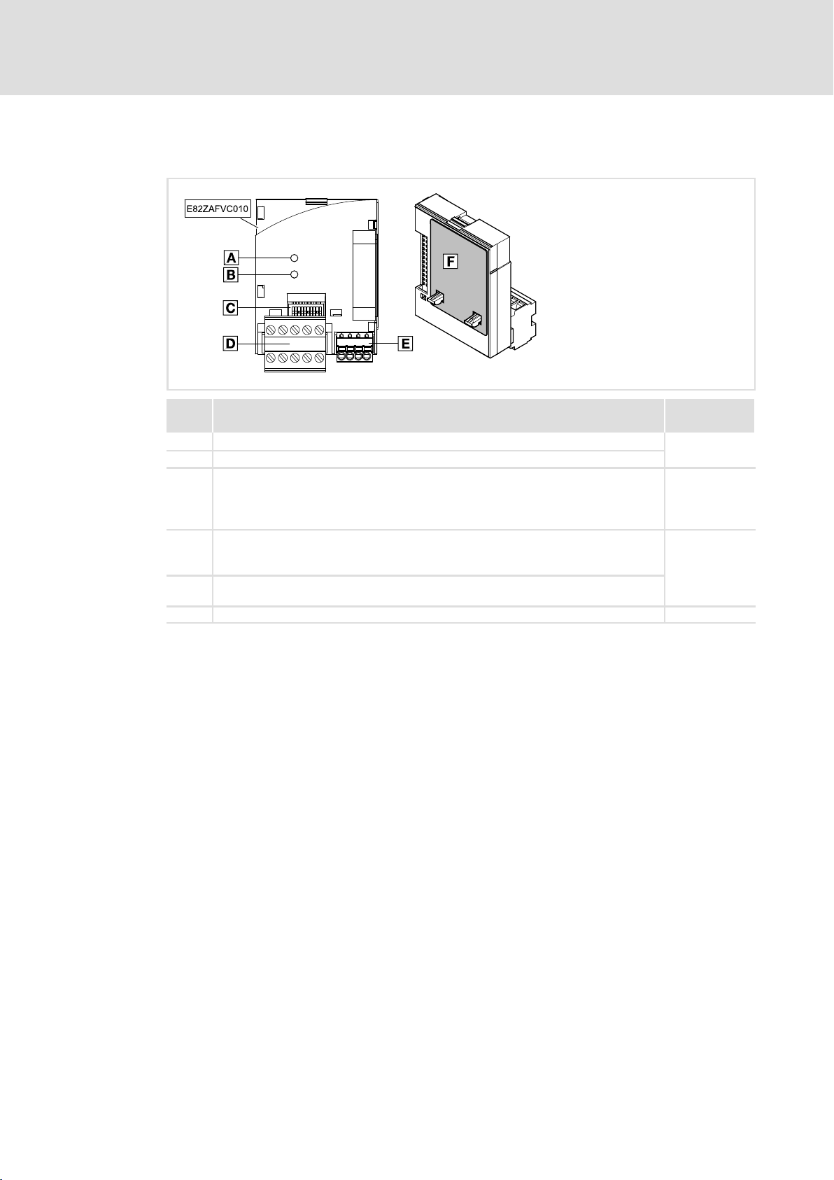
Connections and interfaces
Function module E82ZAFVC010
E82ZAFD101A
Pos. Description Detailed
0
1
2
3
4
5
Status display (two−colour green / red), connection to the standard device
Status display (two−colour green / red), connection to the bus
DIP switches for setting
l Node address ("Address")
l Baud rate ("Bd")
l Compatibility with Lenze function module E82ZAFD (DeviceNet)
Plug connector with double screw connection X3.1, connections for
l DeviceNet
l External voltage supply (via DeviceNet cable)
Plug connector with spring connection X3.2, connections for
l Controller inhibit (CINH)
Nameplate ^ 11
information
^ 34
^ 31
^ 27
14
l
EDS82ZAFVCxxx EN 4.0
Page 15

4 Technical data
4.1 General data
Field Values
Communication profile DeviceNet
Communication medium DIN ISO 11898
Network topology Line terminated at both ends (R = 120 Ohms)
Max. number of devices 63
DeviceNet device Slave
Baud rate [kbit/s] 125, 250, 500
Achievable bus cable length Depending on the cable used, see ^ 28
External voltage supply See^ 24
4.2 Operating conditions
Technical data
General data
4
Ambient conditions
Climate
Storage
Transport IEC/EN 60721−3−2 2K3 (−25 to +70 °C)
Operation Corresponding to the data of the Lenze standard device used (see documentation
Pollution EN 61800−5−1 Degree of pollution 2
Degree of protection IP20 (protection against accidental contact according to NEMA 250 type 1)
IEC/EN 60721−3−1 1K3 (−25 to +60 °C)
of the standard device).
EDS82ZAFVCxxx EN 4.0
l
15
Page 16

4
Technical data
Protective insulation
4.3 Protective insulation
{ Danger!
Dangerous electrical voltage
If Lenze controllers are used on a phase earthed mains with a rated mains
voltage ³ 400 V, protection against accidental contact is not ensured without
implementing external measures.
Possible consequences:
ƒ Death or serious injury
Protective measures:
ƒ If protection against accidental contact is required for the control terminals
of the controller and the connections of the plugged device modules, ...
– a double isolating distance must exist.
– the components to be connected must be provided with the second
E82ZAFVC001
function module
Protective insulation between bus and ... Type of insulation (acc. to EN 61800−5−1)
l reference earth / PE (X3/SH) Functional insulation
l external supply (X3/V+) No electrical isolation
l supply for CINH (X3/20) No electrical isolation
l controller inhibit, CINH (X3/28) Functional insulation
l power section
– 8200 vector Reinforced insulation
– 8200 motec Reinforced insulation
– starttec Reinforced insulation
l control terminals
– 8200 vector Functional insulation
– 8200 motec Functional insulation
isolating distance.
16
E82ZAFVC010
function module
Protective insulation between bus and ... Type of insulation
l Reference earth / PE (X3.1/SH) Functional insulation
l External supply (X3.1/V+) No functional insulation
l Supply for CINH (X3.2/20) No functional insulation
l Controller inhibit, CINH (X3.2/28) Functional insulation
l 8200 vectorpower unit Double insulation
l 8200 vector control terminals Functional insulation
l
EDS82ZAFVCxxx EN 4.0
Page 17

Technical data
Connection terminals
4
4.4 Connection terminals
E82ZAFVC001
function module
X3/
V+
7 Reference potential 1
39 Reference potential 2 of the controller inhibit (CINH) at X3/28
28 Controller inhibit
20 + 20 V internal for CINH, reference potential 1, load capacity: I
E82ZAFVC010
function module
X3.1/
V+
X3.2/
7
39 Reference potential 2 of controller inhibit (CINH) at X3.2/28
28 Controller inhibit
20 + 20 V internal for CINH, reference potential 1, load capacity: I
External DC voltage supply of the function module:
+24 V DC ±10 %, max. 80 mA
The current flowing via terminal V+ during looping through of the
supply voltage to other devices, is to amount to a maximum of 3 A.
l Start = HIGH (+12 V ... +30 V)
l Stop = LOW (0 V ... +3 V)
Input resistance: 3.3kW
30 mA
External DC voltage supply of the function module:
+24 V DC ±10 %, max. 80 mA
The current flowing via terminal V+ during looping through of the
supply voltage to other devices, is to amount to a maximum of 3 A.
Reference potential 1
l Start = HIGH (+12 V ... +30 V)
l Stop = LOW (0 V ... +3 V)
Input resistance: 3.3kW
30 mA
max
max
=
=
EDS82ZAFVCxxx EN 4.0
l
17
Page 18

4
Technical data
Communication time
4.5 Communication time
The communication time is the time between the start of a request and the arrival of the
corresponding response.
The communication times depend on ...
ƒ the processing time in the controller
ƒ the transmission delay time
– the baud rate
– the telegram length
The communication time is the time between the start of a request and the arrival of the
corresponding response.
The CAN bus communication times depend on ...
ƒ the processing time in the controller (see documentation of the controller)
ƒ Telegram runtime
– baud rate
– telegram length
ƒ the data priority
ƒ the bus load
18
l
EDS82ZAFVCxxx EN 4.0
Page 19
Technical data
Dimensions
4
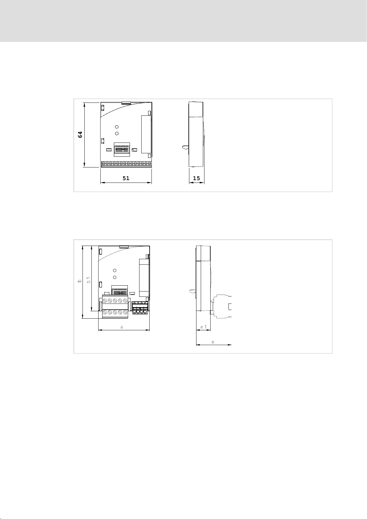
4.6 Dimensions
E82ZAFVC001
function module
E82ZAFVC010
function module
E82ZAFD001E
a51 mm
b 64 mm
c 15 mm
a51 mm
b 72 mm
b1 64 mm
e 30 mm
E1 15 mm
E82ZAFD101B
EDS82ZAFVCxxx EN 4.0
l
19
Page 20

5
Installation
Mechanical installation
Wiring according to EMC (CE−typical drive system)
5 Installation
} Danger!
Inappropriate handling of the function module and the standard device can
cause serious injuries to persons and damage to material assets.
Observe the safety instructions and residual hazards included in the
documentation of the standard device.
( Stop!
The device contains components that can be destroyed by electrostatic
discharge!
Before working on the device, the personnel must ensure that they are free of
electrostatic charge by using appropriate measures.
5.1 Mechanical installation
Follow the notes given in the Mounting Instructions for the standard device for the
mechanical installation of the function module.
The Mounting Instructions for the standard device ...
5.2 Electrical installation
5.2.1 Wiring according to EMC (CE−typical drive system)
ƒ are part of the scope of supply and are enclosed with each device.
ƒ provide tips to avoid damage provide tips to avoid damage through improper
handling.
ƒ describe the obligatory order of installation steps.
For wiring according to EMC requirements observe the following points:
) Note!
ƒ Separate control cables/data lines from motor cables.
ƒ Connect the shields of control cables/data lines at both ends in the case of
digital signals.
ƒ Use an equalizing conductor with a cross−section of at least 16mm
(reference:PE) to avoid potential differences between the bus nodes.
ƒ Observe the other notes concerning EMC−compliant wiring given in the
documentation for the standard device.
2
20
l
EDS82ZAFVCxxx EN 4.0
Page 21
Installation
123 456789 10
123 456789 10
Electrical installation
Wiring with a host (master)
5
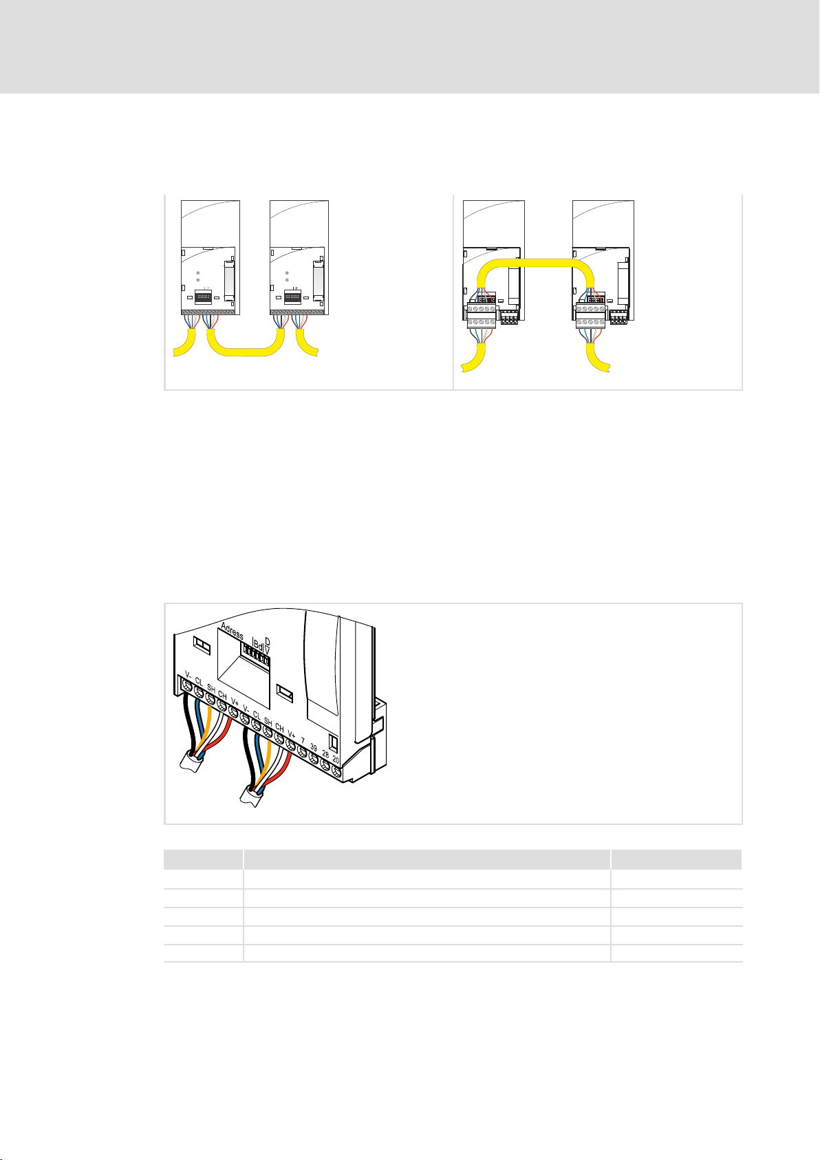
5.2.2 Wiring with a host (master)
The following figure shows the cable routing for the function module:
Adress
V-
CL
SHCHV+
D
Bd
V
V-
SH
20
CL
CH V+
39
7
28
DeviceNet
D
Adress
Bd
V
V-
CL
SHCHV+
V-
SH
20
CL
CH V+
39
7
28
For integrating the function modules a PC with installed configuration software is used.
Specification of the transmission cable
The nodes on the bus system have to be wired with a fieldbus cable (DeviceNet thick or thin
cable ) complying with the DeviceNet specification (DeviceNet Adaption of CIP, Edition 1.1,
Volume Three).
Manufacturers of DeviceNet thick and thin cables for example are Belden Inc., Lapp Group,
C&M Corp., and Madison Cable Corp.
V-
CL
SH
V+
CH
V-
20
39
7
28
20
39
7
28
CL
SH
V+
CH
DeviceNet
E82ZAFD019 E82ZAFD102
Colour code for the DeviceNet cable
Fig. 5−1 DeviceNet wiring with the E82ZAFVC001 function module
Connection Name Colour
V− Reference potential for external voltage supply Black
CL CAN−LOW Blue
SH SHIELD (shining)
CH CAN−HIGH White
V+ External supply voltage Red
E82ZAFD001D
EDS82ZAFVCxxx EN 4.0
l
21
Page 22

5
Installation
Electrical installation
Wiring with a host (master)
Properties of the "Thick Cable" in accordance with DeviceNet specification
General features
Structure Two shielded balanced lines, common axis with drain wire in the centre
Total shielding 65% coverage
Drain wire At least copper 18; at least 19 cores (individually tinned)
Outer diameter 10.41 ... 12.45 mm
Concentricity The radius deviation has to be within 15 % of half the outside diameter.
Cable sheath labelling Name of vendor, part no., and additional labelling
Spec. DC resistance (braid, wrapping, leakage) 5.74 W/km (nom. up to 20 °C)
Certifications (U.S. and Canada) NEC (UL), CL2/CL3 (min.)
Bend radius 20 x diameter (installation) / 7 x diameter (fixed)
Ambient temperature (operation) −20 ... +60 °C at 8 amperes;
Storage temperature −40 ... +85 °C
Pull tension 845.5 N
Features of the data line
Conductor pair At least copper 18; at least 19 cores (individually tinned)
Insulation diameter 3.81 mm (nom.)
Colours Light blue, white
Pair windings / m Approx. 10
Shielding/conductor pair 2000/1000, Al/Mylar, Al side on the outside, w/shorting fold (for tensile load)
Impedance 120 W +/− 10 % at 1 MHz
Capacitance between conductors 39.37 pF/m at 1 kHz (nom.)
Capacitance between one conductor and another which is
connected to the shield.
Capacitive assymetry 3937 pF/km at 1 kHz (nom.)
Spec. DC resistance at 20 °C 22.64 W/km (max.)
Damping 0.43 dB/100 m at 125 kHz (max.)
AWG 36 (at least 0.12 mm) of tin−coated copper braid (individually tinned)
linear current derating to zero at 80 °C
max
78.74 pF/m at 1 kHz (nom.)
0.82 dB/100 m at 500 kHz (max.)
1.31 dB/100 m at 1.00 MHz (max.)
Features of the voltage line
Conductor pair At least copper 15; at least 19 cores (individually tinned)
Insulation diameter 2.49 mm (nom.)
Colours Red / black
Pair windings / m Approx. 10
Shielding/conductor pair 1000/1000, Al/Mylar, Al side on the outside, with w/shorting fold (for tensile load)
Spec. DC resistance at 20 °C 11.81 W/km (max.)
Properties of the "Thin Cable" in accordance with DeviceNet specification
General features
Structure Two shielded balanced lines, common axis with drain wire in the centre
Total shielding 65% coverage
Drain wire At least copper 22; at least 19 cores (individually tinned)
Outer diameter 6.096 ... 7.112 mm
Concentricity The radius deviation has to be within 20 % of half the outside diameter.
Cable sheath labelling Name of vendor, part no., and additional labelling
Spec. DC resistance (braid, wrapping, leakage) 10.5 W/km (nom. at 20 °C)
Certifications (U.S. and Canada) NEC (UL), CL2 (min.)
Bend radius 20 x diameter (installation) / 7 x diameter (fixed)
Ambient temperature (operation) −20 ... +70 °C at 1.5 amperes;
Storage temperature −40 ... +85°C
Pull tension 289.23 N
AWG 36 (at least 0.12 mm) of tin−coated copper braid (individually tinned)
linear current derating to zero at 80 °C
max
22
l
EDS82ZAFVCxxx EN 4.0
Page 23

Installation
Electrical installation
Wiring with a host (master)
Features of the data line
Insulation diameter 1.96 mm (nom.)
Conductor pair At least copper 24; at least 19 cores (individually tinned)
Colours Light blue, white
Pair windings / m Approx. 16
Shielding/conductor pair 1000/1000, Al/Mylar, Al side on the outside, with w/shorting fold (for tensile load)
Impedance 120 W +/− 10 % at 1 MHz
Runtime 4.46 ns/m (max.)
Capacitance between conductors 39.37 pF/m at 1 kHz (nom.)
Capacitance between one conductor and another which is
connected to the shield.
Capacitive assymetry 3.94 pF/km at 1 kHz (max.)
Spec. DC resistance at 20 °C 91.86 W/km (max.)
Damping 0.95 dB/100 m at 125 kHz (max.)
Features of the voltage line
Conductor pair At least copper 22; at least 19 cores (individually tinned)
Insulation diameter 1.4 mm (nominal)
Colours Red, black
Pair windings / m Approx. 16
Shielding/conductor pair 1000/1000, Al/Mylar, Al side on the outside, with w/shorting fold (for tensile load)
Spec. DC resistance at 20 °C 57.41 W/km (max.)
78.74 pF/m at 1 kHz (nom.)
1.64 dB/100 m at 500 kHz (max.)
2.30 dB/100 m at 1.00 MHz (max.)
5
EDS82ZAFVCxxx EN 4.0
l
23
Page 24

5
Installation
Electrical installation
Voltage supply
5.2.3 Voltage supply
) Note!
DeviceNet communication modules from Lenze are only supplied via the
external DeviceNet cable!
Internal wiring of the bus terminals
V
cc
3
5
1
4
8
7
6
2
V
cc
V+
CAN-HIGH
Shield
CAN-LOW
V-
2175DeN007
24
l
EDS82ZAFVCxxx EN 4.0
Page 25

Installation
Electrical installation
Terminal assignment
5
5.2.4 Terminal assignment
Function module E82ZAFVC001
Supply of the controller inhibit (CINH) via the internal voltage source (X3/20)
V-
SH SHCH CH
CLCLV-
X3
_
+
Supply of the controller inhibit (CINH) via the external voltage source
X3
_
+
V+ V+
SH SHCH CH
CLCLV-
V-
V+ V+
GND1
GND2
20
28397
GND1
GND2
28397
20
_
+
Min. wiring required for operation
E82ZAFD003
E82ZAFD006
X3/
V− Reference potential for external voltage supply
CL CAN−LOW CAN data line (LOW)
SH SHIELD Shield
CH CAN−HIGH CAN data line (HIGH)
V+ External supply voltage Please observe notes concerning
7 GND1 Reference potential for X3/20
39 GND2 Reference potential for controller inhibit (CINH) at X3/28
28 CINH Controller inhibit l Start = HIGH (+12 V ... +30 V)
20 DC voltage supply for internal supply of
Name Function Level
external supply!
l Stop = LOW (0 ... +3 V)
+20 V (ref.: GND1)
controller inhibit (CINH)
) Note!
Use the Thin" cable to wire the function module ^ 22.
EDS82ZAFVCxxx EN 4.0
l
25
Page 26

5
Installation
Electrical installation
Terminal assignment
Function module E82ZAFVC010
Controller inhibit (CINH) supply via internal voltage source
GND1
GND2
20
GND1
GND2
_
28397
E82ZAFD110
20
28397
X3.1
V-
V+
CHCL SH
X3.2
+
_
Controller inhibit (CINH) supply via external voltage source
X3.1
V-
V+
CHCL SH
X3.2
+
_
+
E82ZAFD112
Min. wiring required for operation
X3.1/
Designation Function Level
V− Reference potential for external supplyvoltage
CL CAN−LOW CAN data line (LOW)
SH SHIELD Shield
CH CAN−HIGH CAN data line (HIGH)
V+ External supply voltage Please see the notes for external
supply voltage!
X3.2/ Designation Function Level
7 GND1 Reference potential for X3.2/20
39 GND2 Reference potential for controller inhibit (CINH) at X3.2/28
28 CINH Controller inhibit l Start = HIGH (+12V...+30V)
l Stop = LOW (0 ... +3 V)
20 DC voltage source for internal supply of
+20 V (ref.: GND1)
controller inhibit (CINH)
26
l
EDS82ZAFVCxxx EN 4.0
Page 27

Installation
Electrical installation
Cable cross−sections and screw−tightening torques
5
5.2.5 Cable cross−sections and screw−tightening torques
Function module E82ZAFVC001
Range Values
Electrical connection Terminal strip with screw connection
Possible connections
Tightening torque 0.22 ... 0.25 Nm (1.9 ... 2.2 lb−in)
Bare end 5 mm
rigid:
1.5 mm
flexible:
without wire end ferrule
1.0 mm
with wire end ferrule, without plastic sleeve
0.5 mm
with wire end ferrule, with plastic sleeve
0.5 mm
Function module E82ZAFVC010
Field Values
Electrical connection Plug connector with double screw connection
Possible connections
Tightening torque 0.5 ... 0.6 Nm (4.4 ... 5.3 lb−in)
Stripping length 10 mm
rigid:
1.5 mm
flexible:
without wire end ferrule
1.5 mm
with wire end ferrule, without plastic sleeve
1.5 mm
with wire end ferrule, with plastic sleeve
1.5 mm
2
(AWG 16)
2
(AWG 18)
2
(AWG 20)
2
(AWG 20)
2
(AWG 16)
2
(AWG 16)
2
(AWG 16)
2
(AWG 16)
Field Values
Electrical connection 2−pin plug connector with spring connection
Possible connections
Stripping length 9 mm
EDS82ZAFVCxxx EN 4.0
rigid:
flexible:
l
2
1.5 mm
without wire end ferrule
1.5 mm
with wire end ferrule, without plastic sleeve
1.5 mm
with wire end ferrule, with plastic sleeve
1.5 mm
(AWG 16)
2
(AWG 16)
2
(AWG 16)
2
(AWG 16)
27
Page 28

5
Installation
Electrical installation
Bus cable length
5.2.6 Bus cable length
Depending on the baud rate and the cable type used (thick cable/thin cable), the following
bus cable lengths are possible:
Baud rate [kbps]
125
250
500
If both thick and thin cable types are used, the maximum cable lengths can be defined
according to the baud rates as follows:
Baud rate [kbps] Max. bus cable length
125 500 m = L
250 250 m = L
500 100 m = L
L
: thick cable length
thick
L
: thin cable length
thin
) Note!
Select a baud rate in dependency of the data volume, cycle time and number
of nodes just high enough to suit your application.
Bus cable lengths [m]
Thick cable Thin cable
500
250
100
thick
thick
thick
+ 5 L
+ 2.5 L
+ L
thin
thin
thin
100
5.2.7 Use of plug connectors
( Stop!
Observe the following to prevent any damage to plug connectors and
contacts:
ƒ Only pug in / unplug the plug connectors when the controller is
disconnected from the mains.
ƒ Wire the plug connectors before plugging them in.
ƒ Unused plug connectors must also be plugged in.
Use of plug connectors with spring connection
E82ZAFX013
28
l
EDS82ZAFVCxxx EN 4.0
Page 29

6 Commissioning
During commissioning, system−dependent data as e.g. motor parameters, operating
parameters, responses and parameters for fieldbus communication are selected for the
controller.
In Lenze devices, this is done via codes. The codes are stored in numerically ascending order
in the Lenze controllers and in the plugged−in communication/function modules.
In addition to these configuration codes, there are codes for diagnosing and monitoring
the bus devices.
6.1 Before switching on
( Stop!
Before you switch on the basic device with the function module for the first
time, check
ƒ the entire wiring for completeness, short circuit and earth fault.
ƒ whether the bus system is terminated by terminating resistors at the first
and last bus station.
Commissioning
Before switching on
6
6.2 Commissioning steps
) Note!
ƒ For software version < 3.5 of the basic devices:
If you keep to the switch−on sequence decribed in the following table (basic
device must be switched on before the function module), a communication
error is indicated by the basic device.
This error message can be
– avoided by switching on the function module first and then the basic
device.
– automatically deleted by activating the function "Automatic trip reset" via
code C1566 (see chapter "Code table").
ƒ For software versions ³ 3.5 of the basic devices:
Keep to the switch−on sequence described in the commissioning steps (table
below).
EDS82ZAFVCxxx EN 4.0
l 29
Page 30

6
Commissioning
Commissioning steps
Step Procedure see
1. If necessary, set the software compatibility
2. Set the node address
3. Set the baud rate
4. Inhibit the standard device via terminal 28 (CINH).
Terminal 28 on LOW potential.
The standard device can be inhibited and enabled via the bus
5. Connect mains voltage
6. Connect the separate voltage supply for the function module
(Switch on the DeviceNet).
Response of the front LED display:
Directly after the voltage supply for the function module has been connected, both
LEDs at the front light up for a short time in the following order:
l The LED Status of connection with bus" changes its colour from green to red
before it goes off.
l The LED "Status of the connection to the standard device" changes its colour
from green to red before it goes off.
l The LED Connection status to the bus" at the front of the function module is
blinking (only visible in case of 8200 vector).
l The green LED Status of connection with standard device" at the front of the
function module is on (only visible in case of 8200 vector).
l Keypad: dc(if attached)
7.
Configure the host system for communicating with the function module with
configuration software:
l With explicit messages" all parameters can be read or written from the drive
and/or function module.
l Actual values can be read (e.g. status word) or setpoints can be written (e.g.
frequency setpoint) via the I/O data.
^ 31
Manual of the
standard device
^ 24
^ 34
Response
l The LED Status of connection with the bus" at the front of the function module
changes from blinking to the constantly ON state.
8. Configure process data channel of the standard device (see "application range") for
operation with the function module.
Recommendation
Set code C0005 = 200 after the Lenze setting has been loaded (C0002).
C0005 = 200 preconfigures the device for the operation with a function module.
Control and status words are already linked.
Continue with step 12.
9. If required, assign the process output data of the master/scanner via C1511 to the
input signals of the standard device.
10. If required, assign the process input words of the master/scanner to the output
signals of the standard device via C1510.
11. If the configuration in step 9. or step 10. has been changed:
Enable process output data with C1512 = 65535.
12. Enable standard device with terminal 28 (CINH) (terminal 28 on HIGH).
13. Send setpoint via a selected process data output word.
The drive is now running.
14. Inhibit the standard device via the bus (e.g. control word bit 9) or terminal 28 (CINH).
Manual of the
standard device
^ 44
^ 41
^ 47
l 30
EDS82ZAFVCxxx EN 4.0
Page 31

Possible settings using the front switch
6.3 Controls and displays
6.3.1 Possible settings using the front switch
) Note!
Settings via GDC, operating module or configuration software
The settings of device address and baud rate via GDC, the operating module or
the configuration software only become valid when the DIP switches S7 and
S8 are in the "ON" position.
Settings via front switch
The Lenze setting of all switches is OFF.
The device address and baud rate set via DIP switch will only be active after a
renewed mains connection.
The switch S9 is ineffective.
The following settings can be easily carried out via the front DIP switch of the function
module:
Commissioning
Controls and displays
6
ƒ Software compatibility of E82ZAFVC / E82ZAFD function module with S10
ƒ Device address with S1 − S6
ƒ Baud rate with S7 / S8
Adjustment of software compatibility
) Note!
Set the baud rate with S8/S9 if the controller is compatible with the E82ZAFD
function module (S10=ON).
ON
1627438
Fig. 6−1 Software compatibility setting
Compatibility S10
E82ZAFVC0xx OFF
E82ZAFD
For the description of the function
module see the E82ZAFD Mounting
Instructions
5
910
ON
OFF
E82ZAFD005
ON
EDS82ZAFVCxxx EN 4.0
l
31
Page 32

6
Commissioning
Controls and displays
Possible settings using the front switch
Setting of the device address
) Note!
The device address must be set via software, when the switches S7 and S8 are
in ON position.
In this case the switches S1 to S6 are ineffective.
ON
1627438
Fig. 6−2 Address assignment via DIP switch
5
910
ON
OFF
) Note!
The addresses of all controllers connected to the network must differ from
each other.
The device address (decimal number) is calculated by inserting the positions of the
switches S1 ... S6 (’0’ = OFF and ’1’ = ON) into the following equation:
Address
= S6 · 20 + S5 · 21 + S4 · 22 + S3 · 23 + S2 · 24 + S1 · 2
dec
The equation also allows you to calculate the valency of a confirmed switch. The sum of
valencies results in the device address to be set:
Switch Valency
S1 32 ON
S2 16 ON
S3 8 ON
S4 4 OFF
S5 2 OFF
S6 1 OFF
Switch position Address
5
Example
32 + 16+ 8 = 56
32
l
EDS82ZAFVCxxx EN 4.0
Page 33

Baud rate setting
) Note!
The baud rate must be the same for all devices and the scanner.
ON
Commissioning
Controls and displays
Possible settings using the front switch
ON
6
1627438
Fig. 6−3 Baud rate setting
Baud rate S7 S8
125 kbits/s OFF OFF
250 kbits/s OFF ON
500 kbits/s ON OFF
Setting of baud rate (and node address) via software
configuration.
The baud rate can be
l set manually via software or
l automatically detected.
5
910
OFF
ON ON
) Note!
Set the baud rate with S8/S9 if the controller is compatible with the E82ZAFD
function module (S10=ON).
EDS82ZAFVCxxx EN 4.0
l
33
Page 34

7
Diagnostics
LED status displays
7 Diagnostics
7.1 LED status displays
Function module E82ZAFVC001 Function module E82ZAFVC010
E82ZAFD001A* E82ZAFD101A*
Pos Colour Status Notes
1
green
red
2
green
red
off Function module is not supplied with voltage,
external voltage supply is switched off
blinking Function module is supplied with voltage but not connected to the controller.
Reason:
Standard device is
l switched off
l is being initialised
l not available
on Function module is supplied with voltage and is connected to the standard
device
blinking Internal error, Lenze setting has been loaded
on Internal error of the function module
off l No connection to the master
l Function module is not supplied with voltage.
blinking Dup_Mac_ID" test phase. Not yet connected to master (scanner).
on DeviceNet connection established.
blinking No communication due to time−out
on Critical bus error
l 34
EDS82ZAFVCxxx EN 4.0
Page 35

Protection against uncontrolled restart
) Note!
Establishing communication
If communication is to be established via an externally supplied
communication module, initially the standard device must also be switched
on.
After communication has been established, the externally supplied module is
independent of the power on/off state of the standard device.
Protection against uncontrolled restart
After a fault (e.g. short−term mains failure), a restart of the drive is not always
wanted and − in some cases − even not allowed.
The restart behaviour of the controller can be set in C0142:
ƒ C0142 = 0 (Lenze setting)
– The controller remains inhibited (even if the fault is no longer active).
– The drive starts up in a controlled manner by explicit controller enable:
93XX: Set terminal 28 to HIGH level.
ECSXX: Set terminals X6/SI1 and X6/SI2 to HIGH level.
ƒ C0142 = 1
– An uncontrolled restart of the drive is possible.
Diagnostics
LED status displays
7
EDS82ZAFVCxxx EN 4.0
l 35
Page 36

7
Diagnostics
Troubleshooting and fault elimination
7.2 Troubleshooting and fault elimination
No communication with the controller.
Possible causes Diagnostics Remedy
Is the controller switched on? One of the operating status LEDs of
Is the communication module
supplied with voltage?
Does the controller receive
telegrams?
the basic device must be on.
The LED "Connection status to the
basic device" must be lit or blinking
green.
The LED "Connection status to the
bus" at the communication module
must be blinking green when
communicating with the master
computer.
Supply controller with voltage.
Check the external voltage supply.
The measured voltage value at the
terminals for external voltage
supply of the communication
module must be in the range of 24V
± 10%.
The communication module has not
yet been initialised with the
controller.
Possibility 1: controller not switched
on
Possibility 2: check the connection to
the controller
Check your wiring (see ^ 20).
Check whether your master
computer sends telegrams.
Check the data assignment in the
scan list (I/0 mapping).
Is the available device address
already assigned?
Check the setting of the other nodes
on the DeviceNet.
l 36
EDS82ZAFVCxxx EN 4.0
Page 37

8 Codes
How to read the code table
Column Meaning
Code
Subcode Subcode
Name Designation of the Lenze code
Index Index under which the parameter is addressed.
Lenze
Values
Access R = read access (reading permitted)
Data type l FIX32: 32−bit value with sign; decimal with 4 decimal positions
Codes 8
(Lenze) code
l The parameters of a configurable code marked with an asterisk (<Code>*) can only be accessed
via the communication module.
l The value of a configurable code marked with a double asterisk (<Code>**) is not transmitted
with the parameter set transfer.
Lenze setting of the code
g Display code
Configuration of this code is not possible.
Fixed values determined by Lenze (selection list) or a value range:
Minimum value [Smallest increment/unit] Maximum value
W = write access (writing permitted)
l U16: 2 bytes bit−coded
l U32: 4 bytes bit−coded
l VS: visible string, character string with defined length
EDS82ZAFVCxxx EN 4.0
l
37
Page 38

Codes8
C0002: Parameter set management
(extract from code table)
Possible settings
Code Subcode
C0002 0 0 FIX32
Parameter set management (selection 0):
Selection Important
0 Ready PAR1 ... PAR4:
Lenze Selection
l Parameter sets of the controller
l PAR1 ... PAR4
FPAR1:
l Module−specific parameter set of the DeviceNet function
module
l FPAR1 is stored in the function module
Data type
Restoring the delivery state:
Selection Important
1 Lenze setting ðPAR1
2 Lenze setting ðPAR2
3 Lenze setting ðPAR3
4 Lenze setting ðPAR4
31 Lenze setting ðFPAR1 Restoring the delivery state in the function module
61 Lenze setting ðPAR1 + FPAR1
62 Lenze setting ðPAR2 + FPAR1
63 Lenze setting ðPAR3 + FPAR1
64 Lenze setting ðPAR4 + FPAR1
Restoring the delivery state in the selected parameter set
Restoring the delivery state in the selected parameter set of
the controller and the function module
38
l
EDS82ZAFVCxxx EN 4.0
Page 39

Transmitting the parameter sets with the keypad:
Selection Important
Using the keypad, you can transmit the parameter sets to the other controllers.
During the transmission the access to the parameters via other channels is inhibited!
Keypad ð controller
70 with DeviceNet function module
10 (other)
Keypad ð PAR1 (+ FPAR1)
71 with DeviceNet function module
11 (other)
Keypad ð PAR2 (+ FPAR1)
72 with DeviceNet function module
12 (other)
Keypad ð PAR3 (+ FPAR1)
73 with DeviceNet function module
13 (other)
Keypad ð PAR4 (+ FPAR1)
74 with DeviceNet function module
14 (other)
Controller ð keypad
80 with DeviceNet function module
20 (other)
Keypad ð function module
40 only with DeviceNet function module
Function module ð keypad
50 only with DeviceNet function module
Overwrite all available parameter sets (PAR1 ... PAR4, or if
required FPAR1) with the corresponding keypad data
Overwrite the selected parameter set and, if necessary, FPAR1
with the corresponding keypad data
Copy all available parameter sets (PAR1 ... PAR4, or if required
FPAR1) into the keypad
Only overwrite the module−specific parameter set FPAR1 with
the keypad data
Only copy the module−specific parameter set FPAR1 into the
keypad
Codes 8
Save own basic settings:
Selection Important
9 PAR1 ð own basic setting You can store an own basic setting for the controller
5 Own basic setting ðPAR1
6 Own basic setting ðPAR2
7 Own basic setting ðPAR3
8 Own basic setting ðPAR4
parameters (e. g. the delivery state of your machine):
1. Ensure that parameter set 1 is active
2. Inhibit the controller
3. Set C0003 = 3, confirm with v
4. Set C0002 = 9, confirm with v, the own basic setting is
stored
5. Set C0003 = 1, confirm with v
6. Enable the controller
With this function you can simply copy PAR1 into the
parameter sets PAR2 ... PAR4
Restoring the own basic setting in the selected parameter set
EDS82ZAFVCxxx EN 4.0
l
39
Page 40

Codes8
C1500:
Software product code
Possible settings
Code Subcode
C1500 − g − VS
The code contains a strings which is 14 bytes long. The product code will be output, e.g.
82SAFV0C_XXXXX.
C1501: Software date
Code Subcode
C1501 − g − VS
The code contains a string which is 17 bytes long. The date and time the software have
been written will be output, e.g. June 21 2000 12:31.
Lenze Selection
Possible settings
Lenze Selection
Data type
Data type
C1502:
Display of the software product code
Possible settings
Code Subcode
C1502 1 ... 4 g
Lenze Selection
−
Data type
U32
Display of code C1500 in 4 subcodes with 4 digits each.
C1503:
Display of the software date
Possible settings
Code Subcode
C1503 1 ... 4 g
Lenze Selection
−
Data type
U32
Display of code C1501 in 4 subcodes with 4 digits each.
C1509:
Setting of the node address
Possible settings
Code Subcode
C1509 − 63 1 [1] 63 FIX32
Lenze Selection
Data type
Only valid if switches S7 and S8 are in the ON position.
40
) Note!
Switch off and then on again the voltage supply of the function module to
activate the changed settings of the node address.
Please observe that the node addresses are not the same when using several
networked nodes.
l
EDS82ZAFVCxxx EN 4.0
Page 41

Codes 8
C1510:
Configuration of process input data
Possible settings
Code Subcode
C1510 FIX32
1 (PEW1) 1
2 (PEW2) 3
3 (PEW3) 4
4 (PEW 4) 5
5 (PEW 5) 6
6 (PEW 6) 7
7 (PEW 7) 8
8 (PEW 8) 9
9 (PEW 9) 10
10 (PEW 10) 11
11 (PEW11) 12
12 (PEW12) 13
Lenze Selection
See table below
Data type
The assignment of the bit status information or the actual values of the controller to the
max. 12 process data input words (PEW) of the master can be freely configured.
Selection Scaling
1
2
3
4
5
6
7
8
9
10
11
12
13
14
15
16
FIF status word 1 (FIF−STAT1)
FIF status word 2 (FIF−STAT2)
Output frequency with slip (MCTRL1−NOUT+SLIP)
Output frequency without slip (MCTRL1−NOUT)
Apparent motor current (MCTRL1−IMOT)
Actual process controller value (PCTRL1−ACT)
Process controller setpoint (PCTRL1−SET)
Process controller output (PCTRL1−OUT)
Controller load (MCTRL1−MOUT)
DC−bus voltage (MCTRL1−DCVOLT)
Ramp function generator input (NSET1−RFG1−IN)
Ramp function generator output (NSET1−NOUT)
FIF−OUT.W1
FIF−OUT.W2
FIF−OUT.W3
FIF−OUT.W4
16 bits
16 bits
±24000 º ±480 Hz
±24000 º ±480 Hz
214 º 100 % rated device current
±24000 º ±480 Hz
±24000 º ±480 Hz
±24000 º ±480 Hz
±214 º ±100 % rated motor torque
16383 º 565 VDC at 400 V mains
16383 º 325 VDC at 230 V mains
±24000 º ±480 Hz
±24000 º ±480 Hz
16 bits or 0 ... 65535
16 bits or 0 ... 65535
0 ... 65535
0 ... 65535
) Note!
ƒ FIF−OUT.W1 is digitally defined in the Lenze setting and assigned with the
16 bits of the controller status word 1 (C0417).
ƒ Before you assign an analog signal source (C0421/3 ¹ 255), the digital
assignment must be deleted (C0417/x = 255)! Otherwise the output signal
would be incorrect.
EDS82ZAFVCxxx EN 4.0
l
41
Page 42

Codes8
C0417/1
C0417/16
C0421/3
C0418/1
C0418/16
C0421/4
C0421/5
NSET1
PCTRL1
MCTRL1
DCTRL1
…...
…...
STAT 1
STAT1.B0
…...
STAT1.B15
STAT 2
STAT2.B0
…...
STAT2.B15
MCTRL1-NOUT+SLIP
MCTRL1-NOUT
MCTRL1-IMOT
PCTRL1-ACT
PCTRL1-SET1
PCTRL1-OUT
MCTRL1-MOUT
MCTRL1-DCVOLT
NSET1-RFG1-IN
NSET1-NOUT
FIF-OUT.W1.B0
…...
FIF-OUT.W1.B15
FIF-OUT.W2.B0
…...
FIF-OUT.W2.B15
FIF-STAT.B0
FIF-STAT.B1
…
FIF-STAT.B14
FIF-STAT.B15
FIF-STAT.B16
FIF-STAT.B17
…
FIF-STAT.B30
FIF-STAT.B31
16 Bit
16 Bit
16 Bit
16 Bit
16 Bit
16 Bit
16 Bit
16 Bit
16 Bit
16 Bit
16 Bit
16 Bit
16 Bit
16 Bit
16 Bit
FIF-OUT
Byte1
Byte 2
Byte 3
Byte 4
Byte 5, 6
Byte 7, 8
Byte 9, 10
Byte 11, 12
Byte 13, 14
Byte 15, 16
Byte 17, 18
Byte 19, 20
Byte 21, 22
Byte 23, 24
Byte 25, 26
Byte 27, 28
Byte 29, 30
FIF-STAT1
FIF-STAT2
FIF-OUT.W1
FIF-OUT.W2
FIF-OUT.W3
C1510/1 = 1
C1510/2 = 3
C1510/3 = 4
C1510/4 = 5
C1510/5 = 6
C1510/6 = 7
C1510/7 = 8
C1510/8 = 9
C1510/9 = 10
C1510/10 = 11
C1510/11 = 12
C1510/12 = 13
PEW1
PEW2
PEW3
PEW4
PEW5
PEW6
PEW7
PEW8
PEW9
PEW10
PEW11
PEW12
PEW1
PEW2
PEW3
PEW4
PEW5
CH
PEW6
CL
PEW7
PEW8
PEW9
PEW10
PEW11
PEW12
DeviceNet
SH
C0421/6
16 Bit
Byte 31, 32
FIF-OUT.W4
Fig. 8−1 Free configuration of the 12 process input words of the function module with Lenze setting
Symbol Meaning
Combination of signals in the Lenze setting
Fixed signal connection
Analog input (can be freely connected with an analog output which has the same labelling)
Analog output
Digital input (can be freely connected with a digital output which has the same labelling)
Digital output
8200vec513
42
l
EDS82ZAFVCxxx EN 4.0
Page 43

Codes 8
FIF status word 1 (FIF−STAT1) FIF status word 2 (FIF−STAT2)
Bit Assignment Bit Assignment
0 Current parameter set bit 0 (DCTRL1−PAR−B0) 0 Current parameter set bit 1 (DCTRL1−PAR−B1)
01Parameter set 1 or 3 active
Parameter set 2 or 4 active
1 Pulse inhibit (DCTRL1−IMP) 1 TRIP, Q
01Power outputs enabled
Power outputs inhibited
2 I
limit (MCTRL1−IMAX)
max
(If C0014 = 5: Torque setpoint)
01Not reached
Reached
3 Output frequency = frequency setpoint
(DCTRL1−RFG1=NOUT)
01False
True
4 Ramp function generator input 1 = ramp function
01False
5 Q
01Not reached
generator output 1
True
threshold (PCTRL1−QMIN) 5 C0054 < C0156 and NSET1−RFG1−I=O
min
Reached
(NSET1−RFG1−I=O)
6 Output frequency = 0 (DCTRL1−NOUT=0) 6 LP1 warning (fault in motor phase) active
01False
True
7 Controller inhibit (DCTRL1−CINH) 7 f < f
01Controller enabled
Controller inhibited
11...8 Device status (DCTRL1−STAT*1 ... STAT*8) 8 TRIP active (DCTRL1−TRIP)
Bit 11 10 9 8
00000100Controller initialisation
00011010Operation inhibited
0 1 0 1 DC−injection brake active
00111101Operation enabled
1 0 0 0 Fault active
1 1 1 1 Communication with basic device not
Switch−on inhibit
Flying−restart circuit active
Message active
possible
12 Overtemperature warning (DCTRL1−OH−WARN) 12
01No warning
− 10 C reached
J
max
13 DC−bus overvoltage (DCTRL1−OV) 13
01No overvoltage
Overvoltage
14 Direction of rotation (DCTRL1−CCW) 14 C0054 > C0156 and NSET1−RFG1−I=0
01CW rotation
CCW rotation
15 Ready for operation (DCTRL1−RDY) 15
01Not ready for operation (fault)
Ready for operation (no fault)
Tab. 8−1 Parameter structure FIF status word (FIF−STATx)
01Parameter set 1 or 2 active
Parameter set 3 or 4 active
or pulse inhibit active (DCTRL1−TRIP−QMIN−IMP)
min
01False
True
2 PTC warning active (DCTRL1−PTC−WARN)
01False
True
3
Reserved
Do not write to this bit!
4 C0054 < C0156 and Q
(DCTRL1−(IMOT<ILIM)−QMIN)
01False
True
(DCTRL1−(IMOT<ILIM)−RFG−I=O)
01False
True
(DCTRL1−LP1−WARN)
01False
True
(NSET1−C0010 ... C0011)
min
01False
True
01False
True
threshold reached
min
9 Motor is running (DCTRL1−RUN)
01False
True
10 Motor is running clockwise (DCTRL1−RUN−CW)
01False
True
11 Motor is running counter−clockwise (DCTRL1−RUN−CCW)
01False
True
Reserved
Reserved
(DCTRL1−(IMOT>ILIM)−RFG−I=O)
01False
True
Reserved
EDS82ZAFVCxxx EN 4.0
l
43
Page 44

Codes8
C1511:
Configuration of process output data
Possible settings
Code Subcode
C1511 FIX32
1 (PAW1) 1
2 (PAW2) 3
3 (PAW3) 4
4 (PAW 4) 5
5 (PAW 5) 6
6 (PAW 6) 7
7 (PAW 7) 8
8 (PAW 8) 9
9 (PAW 9) 10
10 (PAW 10) 11
11 (PAW11) 13
12 (PAW12) 14
Lenze Selection
See table below
Data type
The assignment of the process data output words (PAW) of the master to bit control
commands or setpoints of the controller can be freely configured with C1511.
Selection Scaling
1 FIF control word 1 (FIF−CTRL1)
2 FIF control word 2 (FIF−CTRL2)
3 Setpoint 1 (NSET1−N1)
4 Setpoint 2 (NSET1−N2)
5 Additional setpoint (PCTRL1−NADD)
6 Actual process controller value (PCTRL1−ACT)
7 Process controller setpoint (PCTRL1−SET1)
8 reserved
9 Torque setpoint / limit value (MCTRL1−MSET)
10 PWM voltage(MCTRL1−VOLT−ADD)
11 PWM angle (MCTRL1−PHI−ADD)
12 reserved
13 FIF−IN.W1
14 FIF−IN.W2
15 FIF−IN.W3
16 FIF−IN.W4
16 bits
16 bits
±24000 º ±480 Hz
±24000 º ±480 Hz
±24000 º ±480 Hz
±24000 º ±480 Hz
±24000 º ±480 Hz
214 º 100 % rated motor torque
(
Only for special applications. Please
contact Lenze!
16 bits or 0 ... 65535
16 bits or 0 ... 65535
0 ... 65535
0 ... 65535
44
l
EDS82ZAFVCxxx EN 4.0
Page 45

Codes 8
PAW1
PAW2
PAW3
PAW4
PAW5
PAW6
PAW7
DeviceNet
PAW8
PAW9
PAW10
PAW11
PAW12
FIF-CTRL.B0
FIF-CTRL.B1
FIF-CTRL.B2
FIF-CTRL.B3
…
Byte 1
FIF-CTRL.B4
FIF-CTRL.B5
FIF-CTRL.B6
FIF-CTRL.B7
FIF-CTRL.B8
FIF-CTRL.B9
Byte 2
Byte 3
Byte 4
Byte 25, 26
Byte 27, 28
Byte 29,30
Byte 31,32
FIF-CTRL.B10
FIF-CTRL.B11
…
FIF-CTRL.B12
FIF-CTRL.B13
FIF-CTRL.B14
FIF-CTRL.B15
FIF-CTRL.B16
FIF-CTRL.B17
FIF-CTRL.B18
FIF-CTRL.B19
…
FIF-CTRL.B20
FIF-CTRL.B21
FIF-CTRL.B22
FIF-CTRL.B23
FIF-CTRL.B24
FIF-CTRL.B25
FIF-CTRL.B26
FIF-CTRL.B27
FIF-CTRL.B28
FIF-CTRL.B29
FIF-CTRL.B30
FIF-CTRL.B31
16 Bit
16 Bit
16 Bit
16 Bit
16 Bit
16 Bit
16 Bit
16 Bit
16 Bit
16 Bit
16 Bit
16 Bit
16 Bit
16 Bit
FIF-IN.W1.B0 … FIF-IN.W1.B15
FIF-IN.W2.B0 … FIF-IN.W2.B15
FIF-CTRL1
FIF-CTRL2
PAW1
C1511/1 = 1
PAW2
C1511/2 = 3
PAW3
C1511/3 = 4
PAW4
C1511/4 = 5
PAW5
PAW6
PAW7
PAW8
PAW9
PAW10
PAW11
PAW12
C1511/5 = 6
C1511/6 = 7
C1511/7 = 8
C1511/8 = 9
C1511/9 = 10
C1511/10 = 11
C1511/11 = 13
C1511/12 = 14
CH
CL
SH
Byte 5, 6
Byte 7, 9
Byte 9, 10
Byte 11, 12
Byte 13, 14
Byte 15, 16
Byte 17, 18
Byte 19, 20
Byte 21, 22
Byte 23, 24
FIF-IN.W1
FIF-IN.W2
FIF-IN.W3
FIF-IN.W4
QSP
CINH
TRIP-SET
TRIP-RESET
DCTRL
DCTRL
FIF-RESERVED
FIF-RESERVED
FIF-RESERVED
FIF-RESERVED
FIF-RESERVED
FIF-RESERVED
FIF-RESERVED
FIF-RESERVED
FIF-RESERVED
FIF-RESERVED
FIF-IN.W1
FIF-IN.W2
FIF-IN.W3
FIF-IN.W4
C0410/1 = 200
C0410/2 = 200
C0410/3 = 200
C0410/4 = 200
C0410/5 = 200
C0410/6 = 200
C0410/7 = 200
C0410/8 = 200
C0410/9 = 200
C0410/10 = 200
C0410/11 = 200
C0410/12 = 200
C0410/13 = 200
C0410/14 = 200
C0410/15 = 200
C0410/17 = 200
C0410/18 = 200
C0410/19 = 200
C0410/20 = 200
C0410/21 = 200
C0410/22 = 200
C0410/23 = 200
C0410/24 = 200
C0412/1 = 200
C0412/2 = 200
C0412/3 = 200
C0412/4 = 200
C0412/5 = 200
C0412/6 = 200
C0412/7 = 200
C0412/8 = 200
C0412/9 = 200
FIF-IN
NSET1-JOG1/3
NSET1-JOG2/3
DCTRL1-CW/CCW
DCTRL1-QSP
NSET1-RFG1-STOP
NSET1-RFG1-0
MPOT1-UP
MPOT1-DOWN
RESERVED
DCTRL1-CINH
DCTRL1-TRIP-SET
DCTRL1-TRIP-RESET
DCTRL1-PAR2/4
DCTRL1-PAR3/4
MCTRL1-DCB
DCTRL1-H/RE
PCTRL1-I-OFF
PCTRL1-OFF
RESERVED
PCTRL1-STOP
DCTRL1-CW/QSP
DCTRL1-CCW/QSP
DFIN1-ON
NSET1-N1
NSET1-N2
PCTRL1-NADD
PCTRL1-SET1
PCTRL1-ACT
MCTRL1-MSET
RESERVED
MCTRL1-VOLT-ADD
MCTRL1-PHI-ADD
C0410/x = 30 … 45
C0415/x = 60 … 75
C0417/x = 60 … 75
C0418/x = 60 … 75
C0412/x = 20
C0419/x = 50
C0421/x = 50
C0410/x = 50 … 65
C0415/x = 80 … 95
C0417/x = 80 … 95
C0418/x = 80 … 95
C0412/x = 21
C0419/x = 51
C0421/x = 51
C0412/x = 22
C0419/x = 52
C0421/x = 52
C0412/x = 23
C0419/x = 53
C0421/x = 53
Fig. 8−2 Free configuration of the 12 process output words of the function module with Lenze setting
8200vec512
Symbol Meaning
EDS82ZAFVCxxx EN 4.0
Combination of signals in the Lenze setting
Fixed signal connection
Analog input (can be freely connected with an analog output which has the same labelling)
Analog output
Digital input (can be freely connected with a digital output which has the same labelling)
Digital output
l
45
Page 46

Codes8
FIF control word 1 (FIF−CTRL1) FIF control word 2 (FIF−CTRL2)
Bit Assignment Bit Assignment
0 / 1 JOG values (NSET1−JOG2/3 | NSET1−JOG1/3) 0 Manual/remote changeover (DCTRL1−H/Re)
Bit 1 0
0001C0046 active
1101JOG2 (C0038) active
JOG1 (C0037) active
JOG3 (C0039) active
2 Current direction of rotation (DCTRL1−CW/CCW) 2 Switch off process controller (PCTRL1−OFF)
01Not inverted
Inverted
3 Quick stop (QSP) (FIF−CTRL1−QSP)
01Not active
Active (deceleration via QSP ramp C0105)
4 Stop ramp function generator (NSET1−RFG1−STOP) 4 Stop process controller (PCTRL1−STOP)
01Not active
Active
5 Ramp function generator input = 0 (NSET1−RFG1−0) 5 CW rotation/quick stop (QSP) (DCTRL1−CW/QSP)
01Not active
Active (deceleration via C0013)
6 UP function of motor potentiometer (MPOT1−UP) 6 CCW rotation/quick stop (QSP) (DCTRL1−CCW/QSP)
01Not active
Active
7 DOWN function of motor potentiometer (MPOT1−DOWN) 7 X3/E1 is digital frequency input (DFIN1−ON)
01Not active
Active
8
Reserved
9 Controller inhibit (FIF−CTRL1−CINH) 9
01Controller enabled
Controller inhibited
10 External fault (FIF−CTRL1−TRIP−SET) 10
11 Reset fault (FIF−CTRL1−TRIP−RESET)
0 Þ 1 Bit change resets TRIP
12 / 13 Parameter set changeover
(DCTRL1−PAR3/4 | DCTRL1−PAR2/4)
Bit 13 12
0001PAR1
1101PAR3
PAR2
PAR4
14 DC injection brake (MTCRL1−DCB)
01Not active
Active
15
Reserved
Tab. 8−2 Parameter structure of FIF control word (FIF−CTRLx)
01Not active
Active
1 Switch off I−component of process controller
(PCTRL1−I−OFF)
01Not active
Active
01Not active
Active
3
Reserved
Do not write to this bit!
01Not active
Active
01Not active
Active
01Not active
Active
01Not active
Active
8
11
12
13
14
15
Reserved
Reserved
Reserved
Reserved
Reserved
Reserved
Reserved
Reserved
46
) Note!
Use of bit 5 and bit 6 in FIF control word 2
Set codes C0410/22 (DCTRL1−CW/QSP) and C0410/23 (DCTRL1−CCW/QSP) to
"200".
l
EDS82ZAFVCxxx EN 4.0
Page 47

Codes 8
C1512:
I/O data enable
Possible settings
Code Subcode
C1512 ** − 65535
If C1511 is changed, the process output data is automatically inhibited to ensure data
consistency.
Use the decimal value in code C1512 to enable some or all process output words (PAW)
again:
ƒ 0 = Inhibit PAW
ƒ 1 = Enable PAW
Bit 15 ... 12 Bit 11 Bit 10 ... Bit 1 Bit 0
reserved PAW12 PAW 11 ... POW2 PAW 1
Lenze Selection
0
Data type
[1] 65535 FIX32
The bit settings 0 to 11 are each assigned to a process data word. The bit settings 12 to 15
are reserved.
Use the value 65535 (FFFF
) in code C1512 to release all process output data.
hex
) Note!
ƒ The release is required if the process output data configuration has been
changed.
C1516:
Baud rate setting
Possible settings
Code Subcode
C1516 0 see below FIX32
Selection Baud rate
0 125 kbits/s
1 250 kbits/s
2 500 kbits/s
255 Auto baud (automatic baud rate recognition)
Only valid if switches S7 and S8 are in the ON position.
Lenze Selection
Data type
) Note!
EDS82ZAFVCxxx EN 4.0
Switch off the voltage supply of the function module and then on again to
activate changed settings of the baud rate.
l
47
Page 48

Codes8
C1518:
I/O data length
Possible settings
Code Subcode
C1518 −
This code determines the number of words (I/O input data and I/O output data) being
currently exchanged with the scanner.
A change of the I/O data length must be sent to the scanner via the configuration program.
C1519:
Behaviour in idle state/in case of an error
Code Subcode
C1519 /1 ... /3 0 0 [1] 3 FIX32
Subcode Meaning
1 Setting of the reaction in the event of idle running of the DeviceNet communication.
2 Setting of the reaction if the communication is interrupted (time out)
3 Setting of the reaction if a bus error occurs (duplicateMAC-ID, Bus−Off).
Lenze Selection
4
Possible settings
Lenze Selection
1 [1] 12 FIX32
Data type
Data type
Selection Baud rate
0 No action
1 Fault (TRIP)
2 Controller inhibit
3 Quick stop
C1520:
Display of all words to scanner
Possible settings
Code Subcode
C1520 /1 ... /12 g 0 [1] 65535 U16
Lenze Selection
Data type
Display of the process data input words PEW1 to PEW12 in the corresponding subcodes.
C1521:
Display of all words from scanner
Possible settings
Code Subcode
C1521 /1 ... /12 g 0 [1] 65535 U16
Lenze Selection
Data type
Display of the process data output words 1 ... 12 of the scanner in the corresponding
subcodes.
48
l
EDS82ZAFVCxxx EN 4.0
Page 49

Codes 8
C1522:
Display of all process data words to the basic device
Possible settings
Code Subcode
C1522 1...16 g 0 [1] 65535 U16
Display of the process data words 1 ... 16, which are transferred from the function module
to the basic device:
Subcode Process data word
1 FIF control word 1 (FIF−CTRL1)
2 FIF control word 2 (FIF−CTRL2)
3 Setpoint 1 (NSET1−N1)
4 Setpoint 2 (NSET1−N2)
5 Additional setpoint (PCTRL1−NADD)
6 Actual process controller value (PCTRL1−ACT)
7 Process controller setpoint (PCTRL1−SET1)
8 Reserved
9 Torque setpoint or torque limit value (MCTRL1−MSET)
10 PWM voltage(MCTRL1−VOLT−ADD)
11 PWM angle (MCTRL1−PHI−ADD)
12 Reserved
13 FIF−IN.W1
14 FIF−IN.W2
15 FIF−IN.W3
16 FIF−IN.W4
Lenze Selection
Data type
EDS82ZAFVCxxx EN 4.0
l
49
Page 50

Codes8
C1523:
Display of all process data words from the basic device
Possible settings
Code Subcode
C1523 1...16 g 0 [1] 65535 U16
Display of the process data words 1 ... 16, which are transferred from the basic device to the
function module:
Subcode Process data word
1 FIF status word 1 (FIF−STAT1)
2 FIF status word 2 (FIF−STAT2)
3 Output frequency with slip (MCTRL1−NOUT+SLIP)
4 Output frequency without slip (MCTRL1−NOUT)
5 Apparent motor current (MCTRL1−IMOT)
6 Actual process controller value (PCTRL1−ACT)
7 Process controller setpoint (PCTRL1−SET)
8 Process controller output (PCTRL1−OUT)
9 Controller load (MCTRL1−MOUT)
10 DC bus voltage (MCTRL1−DCVOLT)
11 Ramp function generator input (NSET1−RFG1−IN)
12 Ramp function generator output (NSET1−NOUT)
13 FIF−OUT.W1
14 FIF−OUT.W2
15 FIF−OUT.W3
16 FIF−OUT.W4
Lenze Selection
Data type
C1524:
Display of the currently used baud rate
Code Subcode
C1524 − g
Possible settings
Lenze Selection
0 [1] 2
0 = 125 kbits/s
1 = 250 kbits/s
2 = 500 kbits/s
Data type
FIX32
50
l
EDS82ZAFVCxxx EN 4.0
Page 51

Codes 8
C1525:
Display of current DIP switch setting
Possible settings
Code Subcode
C1525
1
2 0 [1] 3
3 0 [1] 1
This code reflects the switch position being set at the moment.
Subcode 1, node address:
Switch S1 S2 S3 S4 S5 S6
Valency 32 16 8 4 2 1
Subcode 2, baud rate:
Switch S7 S8
Valency 2 1
Lenze Selection
g
0 [1] 63
Data type
FIX32
Subcode 3, compatibility with E82ZAFD:
Switch S10
Valency 1
C1528:
Display of interruption in communication
Possible settings
Code Subcode
C1528 − g 1: Time out during communication FIX32
Lenze Selection
Data type
C1529:
Idle mode display)
Possible settings
Code Subcode
C1529 − g 1:
Lenze Selection
Communication is in idle mode.
Data type
FIX32
EDS82ZAFVCxxx EN 4.0
l
51
Page 52

Codes8
C1566:
Automatic trip reset communication error
Possible settings
Code Subcode
C1566 − 0 0 / 1 FIX32
Selection Meaning
0 No trip reset
1 One−time trip reset of communication monitoring to the basic device
The recommended switch−on sequence is as follows:
1. Switch on DeviceNet
2. Switch on the basic device
If the order is reversed, a communication error is indicated.
Lenze Selection
Data type
With code C1566 = 1, this message is always automatically reset once after switching on
the DeviceNet supply voltage.
) Note!
If the software is compatible with theE82ZAFD function module (DIP switch
S10), this function is not active.
52
l
EDS82ZAFVCxxx EN 4.0
Page 53

9 Appendix
9.1 Data transfer
) Note!
When using the DeviceNet communication profile, the corresponding
specified terminology must be considered. Note that translation into German
is not always permissible.
In these instructions, the following terms are used with the same meaning:
ƒ I/O data «Process data
– Input data is process data to the scanner
– Output data is process data from the scanner
ƒ Explicit Messages «Parameter data
ƒ Scanner « DeviceNet master
Appendix
Data transfer
9
EDS82ZAFVCxxx EN 4.0
l
53
Page 54

9
Appendix
Data transfer
Two different telegram types are transferred between master computer and controller(s):
ƒ I/O data
ƒ Explicit messages
As indicated in the table, these telegram types are subdivided into communication
channels according to their time−critical response:
Communication channel Telegram type
à Parameter data channel
l Enables the access to all Lenze codes.
l Automatic storage after a change of
frequency inverter parameters:
– 8200 vector
– 8200 motec
à Process data channel
– You can control the controller using
the I/O data.
– The master computer can directly
access the I/O data. The data is
directly stored into the I/O area of the
PLC.
– I/O data is not stored in the controller,
they are cyclically transferred
between the host and the controllers
(continuous exchange of input and
output data).
à Explicit messages
Explicit messages are used for configuration and parameter setting
of the devices connected to the DeviceNet. The relationship
between two devices is a client−server relationship. The client
sends the request and the server accepts the order and tries to
settle it. The server reacts as follows
l the required data in case of a positive response or
l a fault message in case of a negative response.
à I/O data
I/O Data (process data) is transmitted/received according to the
producer/consumer principle, i. e. there is one transmitter and no
or an arbitrary number of receivers.
The following transmission modes are supported:
l I/O polled messages (polled)
– The Poll command being transmitted from the master,
includes output data for the slave. The slave then transmits
its input data to the master.
l Cyclic I/O
– With cyclic I/O, master and slave create data independently of
each other which are sent according to the settings of a
timer. The user must set the timer.
l Change of State (COS)
– This type of I/O message is a special cyclic message. COS
nodes send their data when the data status is changed.
) Note!
The default message service for the E82ZAFVC function module is the I/O
polled message. Other services can be released by means of a DeviceNet
Manager tool.
54
l
EDS82ZAFVCxxx EN 4.0
Page 55

Appendix
Data transfer
Overview of the implemented objects for the function module
9
9.1.1 Overview of the implemented objects for the function module
A device connected to the DeviceNet is a conglomeration of objects. Every individual object
is described by its class, instances and attributes. These objects can be used with different
services such as reading or writing.
Overview of the implemented objects:
Object Class Notes
Identity 01
DeviceNet 03
Assembly 04
Connection 05
Acknowledge handler 2B
Lenze
Identity class (01
hex
)
65
66
67
68
6E
hex
hex
hex
hex
hex
hex
hex
hex
hex
hex
−
−
−
−
−
Response to idle mode, communication
interruption and bus error
Changing the I/O data length
I/O image of the transmitted data
I/O image of the received data
Access to Lenze codes
Instance 1:
Attribute Service(s) Description Data type Value
1 GET Vendor ID UINT 445 (01BD
2 GET Device type UINT 0 (generic)
3 GET Product code UINT 768 (0300
4 GET Revision Struct of
Major revision USINT 1 (01
Minor revision USINT 1 (01
5 GET Status WORD Dependent on the current module
6 GET Serial number UDINT Individual for the respective module
7 GET Product name SHORT_STRING e.g. E82ZAFVC"
state
hex
hex
)
hex
)
hex
)
)
Services:
Service code Name Description
0E
05
EDS82ZAFVCxxx EN 4.0
hex
hex
Get_Attribute_Single Reading an attribute
Reset Reset of the communication module
l
55
Page 56

9
Appendix
Data transfer
Overview of the implemented objects for the function module
DeviceNet Class (03
hex
)
Instance 0:
Attribute Service(s) Description Data type Value
1 GET Revision UINT 0002
hex
Instance 1:
Attribute Service(s) Description Data type Value
1 GET MAC ID USINT 0 − 63
2 GET Baud rate USINT 0 − 2
3 GET / SET BOI BOOL 0/1
4 GET Bus−off counter USINT 0 − 255
5 GET
Allocation
information
Allocation choice
byte
Master’s MAC ID USINT 0 – 63
Struct of
BYTE 0 – 63
Services:
Service code Name Description
0E
10
4B
4C
hex
hex
hex
hex
Get_Attribute_Single Reading of an attribute
Set_Attribute_Single Writing of an attribute
Allocate_Master/Slave_Connection_
Set
Release_Group_2_Identifier_Set Connections via Predefined
Demands the application of
Predefined Master/Slave Connection
Set"
Master/Slave Connection Set" are
deleted
56
l
EDS82ZAFVCxxx EN 4.0
Page 57

Appendix
Data transfer
Overview of the implemented objects for the function module
9
Assembly class (04
hex
)
Instance 101 ... 112:
Attribute Service(s) Description Data type Instance / value
3 GET / SET Data Array of BYTE
Instance 101:
1 word (= 2 byte) from master
Instance 102:
2 words (= 4 byte) from master
Instance 103:
3 words (= 6 byte) from master
Instance 104:
4 words (= 8 byte) from master
Instance 105:
5 words (= 10 byte) from master
Instance 106:
6 words (= 12 byte) from master
Instance 107:
7 words (= 14 byte) from master
Instance 108:
8 words (= 16 byte) from master
Instance 109:
9 words (= 18 byte) from master
Instance 110:
10 words (= 20 byte) from master
Instance 111:
11 words (= 22 byte) from master
Instance 112:
12 words (= 24 byte) from master
EDS82ZAFVCxxx EN 4.0
l
57
Page 58

9
Appendix
Data transfer
Overview of the implemented objects for the function module
Instance 114 ... 125:
Attribute Service(s) Description Data type Entity / value
3 GET / SET Data Array of BYTE
Instance 114:
1 word (= 2 byte) from master
Instance 115:
2 words (= 4 byte) from master
Instance 116:
3 words (= 6 byte) from master
Instance 117:
4 words (= 8 byte) from master
Instance 118:
5 words (= 10 byte) from master
Instance 119:
6 words (= 12 byte) from master
Instance 120:
7 words (= 14 byte) from master
Instance 121:
8 words (= 16 byte) from master
Instance 122:
9 words (= 18 byte) from master
Instance 123:
10 words (= 20 byte) from master
Instance 124:
11 words (= 22 byte) from master
Instance 125:
12 words (= 24 byte) from master
Services:
Service code Name Description
0E
10
hex
hex
Get_Attribute_Single Reading an attribute
Set_Attribute_Single Writing an attribute
58
l
EDS82ZAFVCxxx EN 4.0
Page 59

Appendix
Data transfer
Overview of the implemented objects for the function module
9
Connection Class (05
hex
)
Instance 1 (explicit messages):
Attribute Service(s) Description Data type Value
1 GET state USINT Status of the object
2 GET instance_type USINT 0
3 GET transportClass_
trigger
4 GET produced_
connection_id
5 GET consumed_
connection_id
6 GET initial_comm_
characteristics
7 GET produced_
connection_size
8 GET consumed_
connection_size
9 GET / SET expected_
packet_rate
10/11 Not used No longer defined
12 GET / SET watchdog_
timeout_action
13 GET produced_
connection_
path_length
14 GET produced_
connection_path
15 GET consumed_
connection_
path_length
16 GET consumed_
connection_path
17 GET production_
inhibit_time
BYTE 131 (83
UINT Send CAN identifier
UINT Reception of CAN identifier
BYTE 33 (21
UINT 64 (40
UINT 64 (40
UINT Connection−dependent
USINT Defined reaction to timeout
l 1 = Auto Delete
l 3 = Deferred Delete
UINT 0
EPATH −−−
UINT 0
EPATH −−−
UINT 0
hex
hex
hex
hex
)
)
)
)
EDS82ZAFVCxxx EN 4.0
l
59
Page 60

9
Appendix
Data transfer
Overview of the implemented objects for the function module
Instance 2 (polled I/O data):
Attribute Service(s) Description Data type Value
1 GET state USINT Status of the object
2 GET instance_type USINT 1
3 GET transportClass_
trigger
4 GET produced_
connection_id
5 GET consumed_
connection_id
6 GET initial_comm_
characteristics
7 GET produced_
connection_size
8 GET consumed_
connection_size
9 GET / SET expected_
packet_rate
10/11 Not used No longer defined
12 GET watchdog_
time−out_action
13 GET produced_
connection_
path_length
14 GET produced_
connection_path
15 GET consumed_
connection_
path_length
16 GET consumed_
connection_path
17 GET production_
inhibit_time
BYTE 128/130 (80
UINT Send CAN identifier
UINT Reception of CAN identifier
BYTE 1 (01
UINT Dependent on the number of I/O
UINT Dependent on the number of I/O
UINT Connection−dependent
USINT Defines time−outs
UINT 4
EPATH [20
UINT 4
EPATH [20
UINT 0
hex
data words
data words
, 67
hex
, 68
hex
/82
hex
)
, 24
hex
, 24
hex
hex
hex
hex
, 01]
, 01
)
]
hex
60
l
EDS82ZAFVCxxx EN 4.0
Page 61

Appendix
Data transfer
Overview of the implemented objects for the function module
Instance 4 (COS I/O):
Attribute Service(s) Description Data type Value
1 GET state USINT Status of the object
2 GET instance_type USINT 1
3 GET transportClass_
trigger
4 GET produced_
connection_id
5 GET consumed_
connection_id
6 GET initial_comm_
characteristics
7 GET produced_
connection_size
8 GET consumed_
connection_size
9 GET / SET expected_
packet_rate
10/11 Not used No longer defined
12 GET watchdog_
timeout_action
13 GET produced_conne
ction_path_
length
14 GET produced_
connection_path
15 GET consumed_
connection_
path_length
16 GET consumed_
connection_path
17 GET / SET production_
inhibit_time
BYTE 128/130 (80
UINT Send CAN identifier
UINT Reception of CAN identifier
BYTE 1 (01
UINT Dependent on the number of I/O
UINT Dependent on the number of I/O
UINT Connection−dependent
USINT Defines time−outs
UINT 4
EPATH [20
UINT 4
EPATH [20
UINT 0
hex
data words
data words
, 67
hex
, 68
hex
/82
hex
)
, 24
hex
, 24
hex
hex
hex
hex
, 01
, 01
9
)
]
hex
]
hex
Services:
Service code Name Description
05
0E
10
hex
hex
hex
Reset_Request Reset effect:
l Reset of the watchdog timer
l Communication between scanner and slave in
established status.
Get_Attribute_Single Reading an attribute
Set_Attribute_Single Writing an attribute
EDS82ZAFVCxxx EN 4.0
l
61
Page 62

9
Appendix
Data transfer
Overview of the implemented objects for the function module
Acknowledge Handler Class (2B
hex
)
Instance 1:
Attribute Service(s) Description Data type Value
1 GET / SET Acknowledge
Timer
2 GET Retry Limit USINT 0 – 255 ms (00
3 GET COS Producing
Connection
Instance
UINT 2 – 65534 ms (0002
UINT 4 (0004
default 16ms (0010
1ms
)
hex
Services:
Service code Name Description
0E
10
hex
hex
Get_Attribute_Single Reading an attribute
Set_Attribute_Single Writing an attribute
hex
hex
– FF
hex
hex
–FFFE
)
), default
hex
),
62
l
EDS82ZAFVCxxx EN 4.0
Page 63

Appendix
9
Data transfer
Overview of the implemented objects for the function module
Manufacturer−specific class 100 (64
hex
):
Access to Lenze codes
) Note!
We recommend the use of class 110 (¶ 65).
Instance 0:
Attribute Service(s) Description Data type Value
1 GET Revision UINT 0001
Instance 1:
Attribute Service(s) Description Data type Value
1 GET/SET Explicit Message
Data type instance 1
Byte Request Response
1 Code Low Code Low
2 Code High Code High
3 Subcode Subcode
4 Reserve Status l Value of byte = 0: The message does not contain any faults.
5
..
..
Data_1 Low
Data_1 High
..
..
Data_22 Low
Data_22 High
Lenze Codes
l Value of the byte ¹0: Message is faulty.
Data_1 Low
Data_1 High
..
..
Data_22 Low
Data_22 High
See table below Dependent on order
The value of the byte indicates the fault number (for
explanation see the following table).
hex
Explanation of the fault number:
Error code Explanation
03
04
05
07
08
09
0A
0B
0C
0D
0E
2X
FF
hex
hex
hex
hex
hex
hex
hex
hex
hex
hex
hex
hex
hex
Invalid data type
Subcode no. not accepted
Code no. not accepted
No right to access due to operating state
No right to access due to operating mode
No right to access as parameters are only readable
No general right to access
Data block too long
Collisions with other value ranges
Quit value range
Fault − general value range
Fault − AIF interface
General fault
Services:
Service code Name Description
0E
10
hex
hex
Get_Attribute_Single Reading an attribute
Set_Attribute_Single Writing of an attribute
EDS82ZAFVCxxx EN 4.0
l
63
Page 64

9
Appendix
Data transfer
Overview of the implemented objects for the function module
Manufacturer−specific class 102 (66
hex
)
Instance 0:
Attribute Service(s) Description Data type Value
1 GET Revision UINT 0001
Instance 1:
Attribute Service(s) Description Data type Value
1 GET / SET I/O data length
in words
UINT 1 – 12 (0000
Default: 4, (saved in EEPROM)
Services:
Service code Name Description
0E
10
hex
hex
Get_Attribute_Single Reading an attribute
Set_Attribute_Single Writing an attribute
) Note!
ƒ A change of the I/O data length is reported to the scanner
(produced/consumed data size).
ƒ If the I/O data length is reduced, it must be checked before, if the intended
data length is sufficient for the application.
ƒ If the function modules have to be replaced, the machine manufacturer
must provide an application−specific configuration for the end customer
that differs from the Lenze default setting. A parameterisation that deviates
from the Lenze default setting cannot be executed via Lenze engineering
tools.
hex
hex
– 000C
hex
),
Manufacturer−specific class 103 (67
hex
)
Instance 0:
Attribute Service(s) Description Data type Value
1 GET Revision UINT 0001
hex
Instance 1:
Attribute Service(s) Description Data type Value
1 GET I/O image of the
transmitted data
(input data of the
scanner)
Array of UINT Value according to the words set
Services:
Service code Name Description
0E
hex
Get_Attribute_Single Reading of an attribute
64
l
EDS82ZAFVCxxx EN 4.0
Page 65

Appendix
9
Data transfer
Overview of the implemented objects for the function module
Manufacturer−specific class 104 (68
hex
)
Instance 0:
Attribute Service(s) Description Data type Value
1 GET Revision UINT 0001
hex
Instance 1:
Attribute Service(s) Description Data type Value
1 GET/SET I/O image of the
received data
(output data of
the scanner)
Array of UINT Value according to the words set
Services:
Service code Name Description
0E
hex
10
hex
Manufacturer−specific class 110 (6E
Get_Attribute_Single Reading of an attribute
Set_Attribute_Single Writing of an attribute
):
hex
access to Lenze codes
Instance (Lenze code):
Attribute Service(s) Description Data type Value
Lenze subcode GET / SET Access to Lenze
code (6E
hex
)
Data type of the
Lenze code
Value of the Lenze code/subcode
) Note!
ƒ If the corresponding Lenze code does not have a subcode, the value "1"
must be entered into the attribute.
ƒ The display code cannot be configured by the "SET" service.
EDS82ZAFVCxxx EN 4.0
l
65
Page 66

Index10
10 Index
8200 motec, Use with E82ZAFVC001, 10
8200 vector
− Use with E82ZAFVC001, 10
− Use with E82ZAFVC010, 10
A
Acknowledge Handler Class, 62
Ambient conditions, 15
− Climate, 15
Application as directed, 10
Assembly class, 57
B
Baud rate, 15
− setting, 33
Bus cable length, 15 , 28
C
C0002: Parameter set management, 38
C1500: Software product code, 40
C1501: Software date, 40
C1502: Display of the software product code, 40
C1503: Display of the software date, 40
C1509: Setting of the node address, 40
C1510: Configuration of process input data, 41
C1511: Configuration of process output data, 44
C1512: I/O data enable, 47
C1516: Baud rate setting, 47
C1518: I/O data length, 48
C1519: Behaviour in idle state/in case of an error, 48
C1520: Display of all words to scanner, 48
C1521: Display of all words from scanner, 48
C1522: Display of all process data words to the basic
device, 49
C1523: Display of all process data words from the basic
device, 50
C1524: Display of the currently used baud rate, 50
C1525: Display of current DIP switch setting, 51
C1528 Interruption in communication, 51
C1529 Idle mode display, 51
C1566: Automatic trip reset communication error, 52
Cable cross−sections, 27
Cable specification, 21
− Thick Cable, 22
− Thin Cable, 22
CE−typical drive system, 20
Codes, 37
Commissioning, 29
Commissioning steps, 29
Communication medium, 15
Communication profile, 15
Communication time, 18
Compatibility
− Adjustment of software compatibility, 31
− to the E82ZAFD function module , 12
Connection Class, 59
Connections, 13
Controller inhibit supply, E82ZAFVC010, 26
Controls, 31
D
Data transfer, 53
Definition of notes used, 7
Definitions, 6
Device protection, 9 , 20
DeviceNet Class, 56
Diagnostics, 34
Displays, 31
Double insulation, 16
double insulation, 16
E
E82ZAFVC001
− application range with standard devices, 10
− terminal assignment, 25
E82ZAFVC010
− application range with standard devices, 10
− Terminal assignment, 26
Electrical installation, 20
External DC voltage supply
− E82ZAFVC001, 17
− E82ZAFVC010, 17
66
l
EDS82ZAFVCxxx EN 4.0
Page 67

Index 10
F
Fault elimination, 36
Functional insulation, 16
I
Identification, 11
Identity class, 55
Implemented objects, 55
Installation, 20
− electrical, 20
− mechanical, 20
− Terminals, Assignment, 25
Insulation, 16
Interfaces, 13
L
LED status displays, 34
Lenze codes, 37
− C0002, 38
− C1500, 40
− C1501, 40
− C1502, 40
− C1503, 40
− C1509, 40
− C1510, 41
− C1511, 44
− C1512, 47
− C1516, 47
− C1518, 48
− C1519, 48
− C1520, 48
− C1521, 48
− C1522, 49
− C1523, 50
− C1524, 50
− C1525, 51
− C1528, 51
− C1529, 51
− C1566, 52
M
Manufacturer−specific class
− 102, 64
− 103, 64
− 104, 65
− 110, 65
Mechanical installation, 20
Motor starter, use with E82ZAFVC001, 10
N
Nameplate, 11
Nameplate data, 11
Network topology, 15
Notes, definition, 7
O
Objects
− Acknowledge Handler Class, 62
− assembly class, 57
− Connection Class, 59
− DeviceNet Class, 56
− Identity class, 55
− Implemented, 55
− Manufacturer−specific class 102, 64
− manufacturer−specific class 103, 64
− manufacturer−specific class 104, 65
− manufacturer−specific class 110 , 65
P
Parameter, C0142 (restart protection), 35
Plug connectors, 28
− Use, spring connection, 28
Pollution, 15
Processing time, 18
Product description, 10
− application as directed, 10
Product features, 12
Protection against restart, 35
Protection of persons, 9
Protective insulation, 16
− E82ZAFVC001, 16
− E82ZAFVC010, 16
R
Residual hazards, 9
Restart protection, 35
S
Safety instructions, 8
− application as directed, 10
− definition, 7
− device− and application−specific, 9
− layout, 7
EDS82ZAFVCxxx EN 4.0
l
67
Page 68

Index10
Screw−tightening torques, 27
Setting of the address, 32
Setting of the device address, 32
Settings, Front switch, 31
Specification of the transmission cable, 21
starttec, use with E82ZAFVC001, 10
Status displays, 34
Supply
− E82ZAFVC001, 25
− E82ZAFVC010, 26
Supply of the controller inhibit, E82ZAFVC001, 25
Switch, Possible settings, 31
T
Technical data, 15
Terminal assignment
− E82ZAFVC001, 25
− E82ZAFVC010, 26
Terminals, Assignment, 25
Transmission cable
− specification, 21
− Thick Cable, 22
− Thin Cable, 22
Troubleshooting, 36
Type code, 11
− finding, 11
Type of insulation, 16
U
Usage conditions, Ambient conditions, Climate, 15
Use of plug connectors, 28
V
Validity of the documentation, 4
Voltage supply, 24
Voltage supply, external, 15
W
Wiring according to EMC, 20
Wiring with a host (master), 21
68
l
EDS82ZAFVCxxx EN 4.0
Page 69

Index 10
EDS82ZAFVCxxx EN 4.0
l
69
Page 70

F
(
Ê
ü
© 03/2012
Lenze Drives GmbH
Postfach 10 13 52
D−31763 Hameln
Germany
+49(0)5154/ 82−0
+49(0)5154/ 82−28 00
Lenze@Lenze.de
www.Lenze.com
Service Lenze Service GmbH
Breslauer Straße 3
D−32699 Extertal
Germany
(
Ê
008000/ 2446877 (24 h helpline)
+49(0)5154/ 82−11 12
Service@Lenze.de
EDS82ZAFVCxxx § .IFõ § EN § 4.0 § TD29
10987654321
Q
 Loading...