

Page 1
EDK82ZAFVC001
.51%
Ä.51%ä
Montageanleitung
Mounting Instructions
Instructions de montage
DeviceNet
E82ZAFVC001
Funktionsmodul
Function module
Module de fonction
l
Page 2

, Lesen Sie zuerst diese Anleitung und die Dokumentation zum Grundgerät,
bevor Sie mit den Arbeiten beginnen!
Beachten Sie die enthaltenen Sicherheitshinweise.
, Please read these instructions and the documentation of the standard
device before you start working!
Observe the safety instructions given therein!
, Lire le présent fascicule et la documentation relative à l’appareil de base
avant toute manipulation de l’équipement !
Respecter les consignes de sécurité fournies.
Page 3
E82ZAFV001E
Page 4

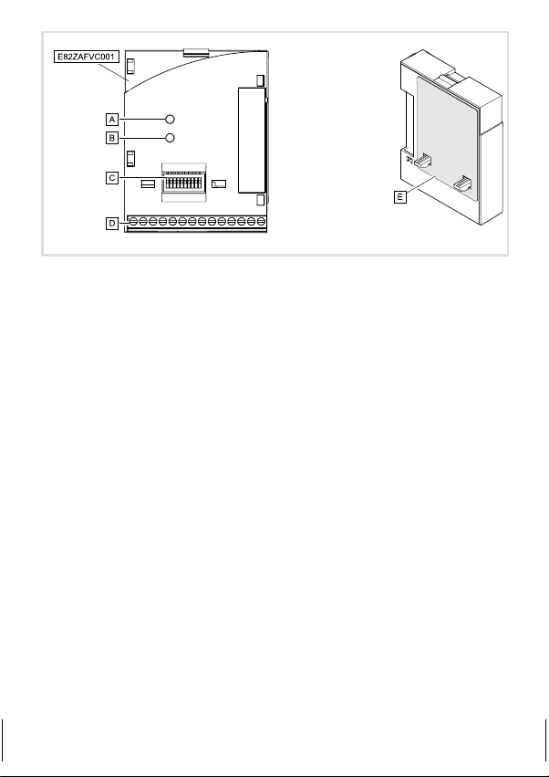
Legende zur Abbildung auf der Ausklappseite siehe
Statusanzeige (bicolor grün / rot), Verbindung zum Grundgerät
0
Statusanzeige (bicolor grün / rot), Verbindung zum Bus
1
DIP−Schalter zur Einstellung von
2
l Knotenadresse ("Adress")
l Übertragungsrate ("Bd")
l Kompatibilität zum Lenze−Funktionsmodul E82ZAFD (DeviceNet)
Klemmleiste X3, Anschlüsse für
3
l DeviceNet
l Reglersperre (CINH)
l Externe Spannungsversorgung (über DeviceNet−Kabel)
Typenschild ^ 5
4
0Abb. 0Tab. 0
^ 28
^ 22
^ 19
I Tipp!
Aktuelle Dokumentationen und Software−Updates zu Lenze Produkten finden
Sie im Internet jeweils im Bereich "Services & Downloads" unter
http://www.Lenze.com
4
l
EDK82ZAFVC001 DE/EN/FR 2.0
Page 5
Gültigkeit
APPLICATION
010 / 3A22
Diese Anleitung ist gültig für
ƒ Funktionsmodule E82ZAFVC001, DeviceNet, ab Version Vx.0x.
Diese Anleitung ist nur gültig zusammen mit der zugehörigen Betriebsanleitung der für den
Einsatz zulässigen Grundgeräte.
Identifikation
APPLICATION
010/ 3A22
L
Type
Id.-No.
Prod.-No.
Ser.-No.
E82AF000P0B201XX
E82ZAFX005
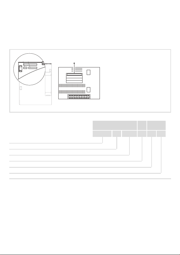
Typenschlüssel E82ZAF V C 001 Vx 0x
Gerätereihe
DeviceNet
Gerätegeneration
Variante 001: verlackte Ausführung
Hardwarestand
Softwarestand
Bestellbezeichnung
E82ZAFVC001Vx0x
Funktion
Das Funktionsmodul koppelt Lenze−Antriebsregler an das serielle Kommunikationssystem
DeviceNet.
EDK82ZAFVC001 DE/EN/FR 2.0
l
5
Page 6

Einsetzbarkeit
Das Funktionsmodul E82ZAFVC001 ist einsetzbar mit folgenden Grundgeräten
Frequenzumrichter 8200 vector Vx14
8200 motec Vx14
Motorstarter starttec Vx1x
ab Version
6
l
EDK82ZAFVC001 DE/EN/FR 2.0
Page 7

Inhalt i
1 Sicherheitshinweise 8 . . . . . . . . . . . . . . . . . . . . . . . . . . . . . . . . . . . . . . . . . . . . . . . . . .
Definition der verwendeten Hinweise 8 . . . . . . . . . . . . . . . . . . . . . . . . . . . . . . . . . . .
Restgefahren 9 . . . . . . . . . . . . . . . . . . . . . . . . . . . . . . . . . . . . . . . . . . . . . . . . . . . . . . . .
2 Lieferumfang 10 . . . . . . . . . . . . . . . . . . . . . . . . . . . . . . . . . . . . . . . . . . . . . . . . . . . . . . .
3 Mechanische Installation 11 . . . . . . . . . . . . . . . . . . . . . . . . . . . . . . . . . . . . . . . . . . . . .
4 Elektrische Installation 12 . . . . . . . . . . . . . . . . . . . . . . . . . . . . . . . . . . . . . . . . . . . . . . .
EMV−gerechte Verdrahtung 12 . . . . . . . . . . . . . . . . . . . . . . . . . . . . . . . . . . . . . . . . . . .
Verdrahtung 13 . . . . . . . . . . . . . . . . . . . . . . . . . . . . . . . . . . . . . . . . . . . . . . . . . . . . . . . .
5 Inbetriebnahme 21 . . . . . . . . . . . . . . . . . . . . . . . . . . . . . . . . . . . . . . . . . . . . . . . . . . . . .
Vor dem ersten Einschalten 21 . . . . . . . . . . . . . . . . . . . . . . . . . . . . . . . . . . . . . . . . . . . .
Einstellmöglichkeiten durch Schalter 22 . . . . . . . . . . . . . . . . . . . . . . . . . . . . . . . . . . .
Übertragungsrate und Adresse einstellen 23 . . . . . . . . . . . . . . . . . . . . . . . . . . . . . . .
Erstes Einschalten 25 . . . . . . . . . . . . . . . . . . . . . . . . . . . . . . . . . . . . . . . . . . . . . . . . . . . .
Statusanzeige 28 . . . . . . . . . . . . . . . . . . . . . . . . . . . . . . . . . . . . . . . . . . . . . . . . . . . . . . .
6 Technische Daten 29 . . . . . . . . . . . . . . . . . . . . . . . . . . . . . . . . . . . . . . . . . . . . . . . . . . . .
Allgemeine Daten und Einsatzbedingungen 29 . . . . . . . . . . . . . . . . . . . . . . . . . . . . . .
Schutzisolierung 30 . . . . . . . . . . . . . . . . . . . . . . . . . . . . . . . . . . . . . . . . . . . . . . . . . . . .
Abmessungen 31 . . . . . . . . . . . . . . . . . . . . . . . . . . . . . . . . . . . . . . . . . . . . . . . . . . . . . . .
EDK82ZAFVC001 DE/EN/FR 2.0
l
7
Page 8

1 Sicherheitshinweise
Definition der verwendeten Hinweise
1 Sicherheitshinweise
Definition der verwendeten Hinweise
Um auf Gefahren und wichtige Informationen hinzuweisen, werden in dieser Dokumentation folgende Piktogramme und Signalwörter verwendet:
Sicherheitshinweise
Aufbau der Sicherheitshinweise:
} Gefahr!
(kennzeichnet die Art und die Schwere der Gefahr)
Hinweistext
(beschreibt die Gefahr und gibt Hinweise, wie sie vermieden werden kann)
Piktogramm und Signalwort Bedeutung
Gefahr von Personenschäden durch gefährliche elektrische
Spannung
{ Gefahr!
} Gefahr!
( Stop!
Anwendungshinweise
Piktogramm und Signalwort Bedeutung
Hinweis auf eine unmittelbar drohende Gefahr, die den Tod
oder schwere Verletzungen zur Folge haben kann, wenn
nicht die entsprechenden Maßnahmen getroffen werden.
Gefahr von Personenschäden durch eine allgemeine Gefahrenquelle
Hinweis auf eine unmittelbar drohende Gefahr, die den Tod
oder schwere Verletzungen zur Folge haben kann, wenn
nicht die entsprechenden Maßnahmen getroffen werden.
Gefahr von Sachschäden
Hinweis auf eine mögliche Gefahr, die Sachschäden zur
Folge haben kann, wenn nicht die entsprechenden Maßnahmen getroffen werden.
) Hinweis!
I Tipp!
,
8
Wichtiger Hinweis für die störungsfreie Funktion
Nützlicher Tipp für die einfache Handhabung
Verweis auf andere Dokumentation
l
EDK82ZAFVC001 DE/EN/FR 2.0
Page 9

Restgefahren
} Gefahr!
Beachten Sie die in den Anleitungen zum Grundgerät enthaltenen
Sicherheitshinweise und Restgefahren.
Sicherheitshinweise
Restgefahren
1
EDK82ZAFVC001 DE/EN/FR 2.0
l
9
Page 10
2 Lieferumfang
2 Lieferumfang
8
9
:
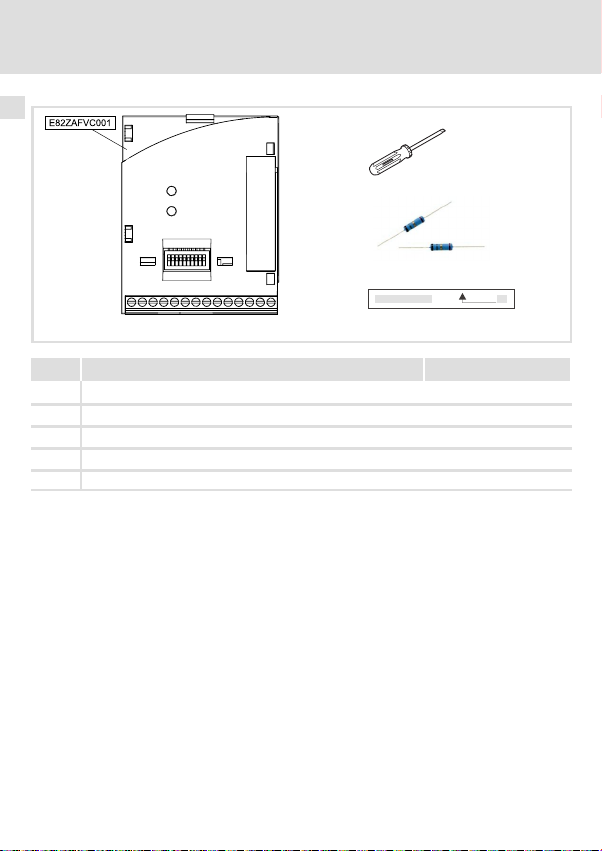
Pos. Element Info
Funktionsmodul E82ZAFVC001
Montageanleitung
Schraubendreher
8
9 Zwei Busabschluss−Widerstände (je 120 W)
Klebestreifen
:
I Tipp!
Ergänzend zu dieser Montageanleitung stellen wir unter der auf Seite 4
angegebenen Internetadresse weitergehende Informationen zu diesem
Funktionsmodul zur Verfügung.
E82ZAFX028/E82ZAFD001E
^ 12
10
l
EDK82ZAFVC001 DE/EN/FR 2.0
Page 11

Mechanische Installation 3
3 Mechanische Installation
Folgen Sie zur mechanischen Installation des Funktionsmoduls den Hinweisen in der Montageanleitung des Grundgerätes.
Die Montageanleitung des Grundgerätes
ƒ ist Teil des Lieferumfangs und liegt jedem Gerät bei.
ƒ gibt Hinweise, um Beschädigungen durch unsachgemäße Behandlung zu vermeiden.
ƒ beschreibt die einzuhaltende Reihenfolge der Installationsschritte.
EDK82ZAFVC001 DE/EN/FR 2.0
l
11
Page 12

4 Elektrische Installation
EMV−gerechte Verdrahtung
4 Elektrische Installation
EMV−gerechte Verdrahtung
Für eine EMV−gerechte Verdrahtung beachten Sie bitte folgende Punkte:
) Hinweis!
ƒ Steuerleitungen getrennt von Motorleitungen verlegen.
ƒ Legen Sie die Schirme der Steuerleitungen bzw. Datenleitungen beidseitig
auf. Für den Schirmanschluss am Funktionsmodul ist die Klemme "SH"
(Shield) vorgesehen.
ƒ Zur Vermeidung von Potenzialdifferenzen zwischen den Grundgeräten der
Kommunikationsteilnehmern eine Ausgleichsleitung mit großem
Querschnitt einsetzen (Bezug: PE).
ƒ Beachten Sie die weiteren Hinweise zur EMV−gerechten Verdrahtung in
den Anleitungen der Grundgeräte.
Allgemeine Angaben zur Verdrahtung
1. DeviceNet−Bustopologie einhalten
2.
Busabschluss−Widerstände von je 120 W (Lieferumfang) anschließen:
l zwischen CAN−LOW und CAN−HIGH
l nur am physikalischen Anfang und Ende der Leitung
3. Busleitung entsprechend der Spezifikation ^ 14 verwenden.
4. Halten Sie die zulässige Busleitungslänge ein (siehe ^ 20).
12
l
EDK82ZAFVC001 DE/EN/FR 2.0
Page 13
Elektrische Installation
123 456789 10
123 456789 10
Verdrahtung
Verdrahtung
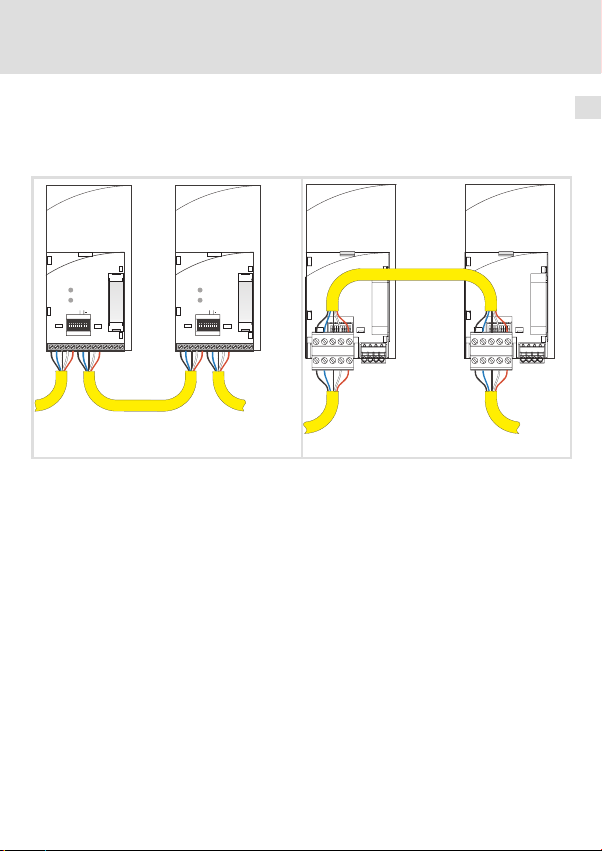
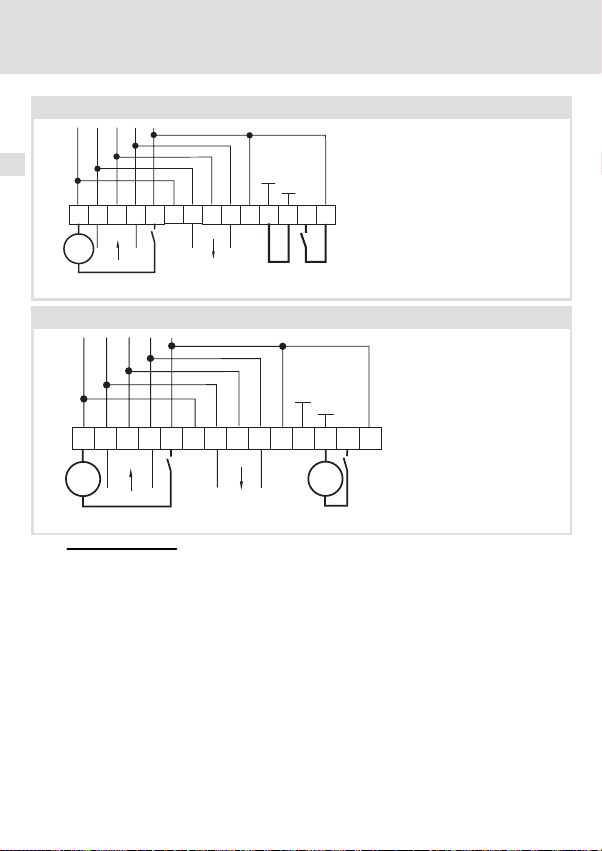
Verdrahtung mit einem Leitrechner
In folgender Abbildung ist die Leitungsführung am Funktionsmodul dargestellt:
4
Adress
V-
CL
SHCHV+
D
Bd
V
V-
SH
20
CL
CH V+
39
7
28
DeviceNet
D
Adress
Bd
V
20
39
7
V-
CL
SHCHV+
V-
SH
20
CL
CH V+
39
7
28
28
V-
CL
SH
V+
CH
V-
20
39
7
28
CL
SH
V+
CH
DeviceNet
E82ZAFD019 E82ZAFD102
Zur Einbindung der Funktionsmodule wird ein PC mit installierter Konfigurationssoftware
verwendet.
EDK82ZAFVC001 DE/EN/FR 2.0
l
13
Page 14

4 Elektrische Installation
Spezifikation des Übertragungskabels
Die Verbindung der Teilnehmer am Bussystem erfolgt mit einer der DeviceNet
tion (DeviceNet Adaption of CIP, Edition 1.1, Volume Three) entsprechenden Feldbusleitung. Unternehmen wie Belden Wire & Cable, Olflex Wire & Cable, C&M Corp. und Madison
Cable produzieren DeviceNet
TM
Thick"− und Thin"−Kabel.
TM
Spezifika-
) Hinweis!
Verwenden Sie das Thin"−Kabel zur Verdrahtung des Funktionsmoduls ^ 14.
Eigenschaften des Thin Cable" gemäß DeviceNet−Spezifikation
Allgemeine Eigenschaften
Anordnung Zwei abgeschirmte symmetrische Leitungen, gemeinsame Achse mit
Gesamtschirmung 65% Abdeckung
Erdungsdraht Kupfer 22 mind.; mind. 19 Adern (einzeln verzinnt)
Außendurchmesser 6,096 mm (min.) bis 7,112 mm (max.)
Rundheit Radiusabweichung muss innerhalb 20% des halben Außendurchmes-
Mantelbeschriftung Verkäufername & Teilenr. und zusätzliche Beschriftung
Spez. DC−Widerstand (Umflechtung, Umwicklung, Ableitung)
Zertifizierungen (U.S. und Canada) NEC (UL), CL2 (min.)
Biegeradius 20 x Durchmesser (Installation) / 7 x Durchmesser (fest)
Umgebungstemperatur − Betrieb −20°C bis +70°C bei 1,5 Ampere; lineare Stromreduzierung auf Null bei
Lagertemperatur −40°C bis +85°C
Zugspannung 289,23 N
Erdungsdraht in der Mitte
AWG 36 oder mind. 0,12mm verzinntes Kupfergeflecht (einzeln verzinnt)
sers liegen
10,5 Ohm/1000 m (nom. bei 20°C)
80°C
max
14
l
EDK82ZAFVC001 DE/EN/FR 2.0
Page 15

Elektrische Installation 4
Eigenschaften der Datenleitung
Isolationsdurchmesser 1,96 mm (nom.)
Leiterpaar Kupfer 24 mind.; mind. 19 Adern (einzeln verzinnt)
Farben Hellblau, weiss
Paarwindungen / m ca. 16
Abschirmung pro Leiterpaar 1000/1000, Al/Mylar, Al−Seite außen, mit Falz zum Kurzschließen (bei
Impedanz 120 Ohm +/− 10% (bei 1 MHz)
Laufzeit 4,46 ns/m (max.)
Kapazität zwischen Leitern 39,37 pF / m bei 1 kHz (nom.)
Kapazität zwischen einem Leiter und einem anderen, der mit dem Schirm verbunden ist
Kapazitive Unsymmetrie 3,94 pF/1000 m bei 1 kHz (max.)
Spez. DC−Widerstand bei 20°C 91,86 Ohm/1000 m (max.)
Dämpfung 0,95 dB/100 m bei 125 kHz (max.)
Eigenschaften der Spannungsleitung
Leiterpaar Kupfer 22 mind.; mind. 19 Adern (einzeln verzinnt)
Isolationsdurchmesser 1,4 mm (nominal)
Farben Rot, schwarz
Paarwindungen/m ca. 16
Abschirmung pro Leiterpaar 1000/1000, Al/Mylar, Al−seite außen, mit Falz zum Kurzschließen (bei
Spez. DC−Widerstand bei 20°C 57,41 Ohm/1000 m (max.)
Zugbelastung)
78,74 pF / m bei 1 kHz (nom.)
1,64 dB/100 m bei 500 kHz (max.)
2,30 dB/100 m bei1.00MHz (max.)
Zugbelastung)
EDK82ZAFVC001 DE/EN/FR 2.0
l
15
Page 16
4 Elektrische Installation
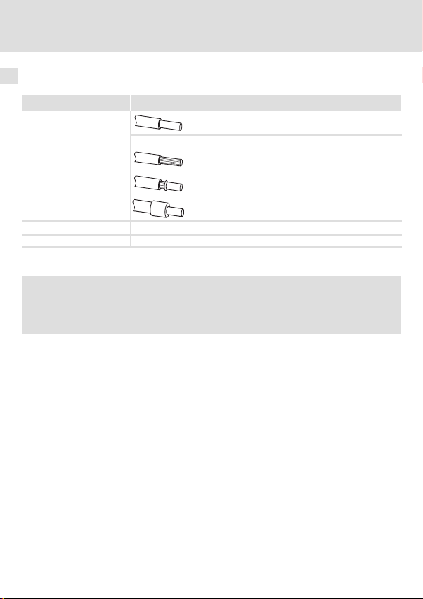
Daten der Anschlussklemmen
Elektrischer Anschluss Klemmleiste mit Schraubanschluss
Anschlussmöglichkeiten
Anzugsmoment 0,22 ... 0,25 Nm (1.9 ... 2.2 lb−in)
Abisolierlänge 5 mm
starr: 1,5 mm
flexibel:
ohne Aderendhülse
1,0 mm
mit Aderendhülse, ohne Kunststoffhülse
0,5 mm
mit Aderendhülse, mit Kunststoffhülse
0,5 mm
2
2
(AWG 18)
2
(AWG 20)
2
(AWG 20)
(AWG 16)
Externe Spannungsversorgung
) Hinweis!
Kommunikationsbaugruppen DeviceNet von Lenze werden ausschließlich
extern über das DeviceNet−Kabel versorgt!
16
l
EDK82ZAFVC001 DE/EN/FR 2.0
Page 17
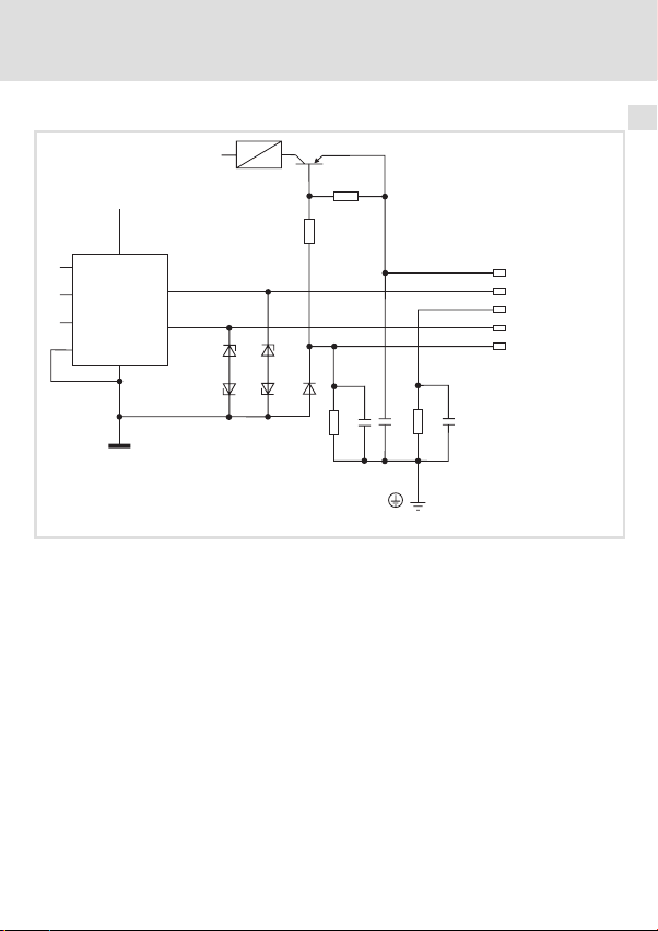
Interne Beschaltung der Busklemmen
V
cc
V
cc
3
5
1
4
8
7
6
2
Elektrische Installation 4
V+
CAN-HIGH
Shield
CAN-LOW
V-
2175DeN007
EDK82ZAFVC001 DE/EN/FR 2.0
l
17
Page 18
4 Elektrische Installation
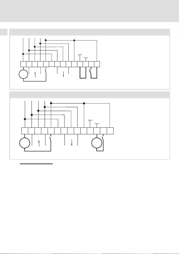
Versorgung der Reglersperre (CINH) über die interne Spannungsquelle (X3/20)
GND1
GND2
28397
X3
SH SHCH CH
CLCLV-
_
V+ V+
V-
20
+
Versorgung der Reglersperre (CINH) über die externe Spannungsquelle
GND1
GND2
28397
20
_
+
18
X3
SH SHCH CH
CLCLV-
_
V+ V+
+
V-
Für den Betrieb notwendige Mindestverdrahtung
l
E82ZAFD003
E82ZAFD006
EDK82ZAFVC001 DE/EN/FR 2.0
Page 19

Elektrische Installation 4
Bezeichnung Funktion Pegel
X3/
V− Bezugspotential für externe Versorgungsspannung
CL CAN−LOW CAN−Datenleitung (LOW)
SH SHIELD Schirm
CH CAN−HIGH CAN−Datenleitung (HIGH)
V+ Externe Versorgungsspannung Bitte Hinweise zur externen Ver-
7 GND1 Bezugspotential für X3/20
39 GND2 Bezugspotential der Reglersperre (CINH) an X3/28
28 CINH Reglersperre
20 DC−Spannungsquelle zur internen Ver-
sorgung der Reglersperre (CINH)
sorgung beachten!
l Start = HIGH (+12 V ... +30 V)
l Stop = LOW (0 ... +3 V)
+20 V (Bezug: GND1)
EDK82ZAFVC001 DE/EN/FR 2.0
l
19
Page 20

4 Elektrische Installation
Erreichbare Busleitungslänge
In Abhängigkeit der Übertragungsrate und des verwendeten Kabels sind folgende Busleitungslängen möglich:
Übertragungsrate Thin Cable Thick Cable
125 kBit/s
250 kBit/s 250 m
500 kBit/s 100 m
Bei gemischter Verwendung der Kabeltypen Thick" und Thin" sind die maximalen Kabellängen in Abhängigkeit der Übertragungsraten wie folgt zu bestimmen:
Übertragungsrate Busleitungslänge
125 kBit/s L
250 kBit/s L
500 kBit/s L
100 m
= 500 m = L
max
= 250 m = L
max
= 100 m = L
max
thick
thick
thick
+ 5 L
+ 2,5 L
+ L
thin
500 m
thin
thin
20
l
EDK82ZAFVC001 DE/EN/FR 2.0
Page 21

Inbetriebnahme
Vor dem ersten Einschalten
5 Inbetriebnahme
Vor dem ersten Einschalten
( Stop!
Bevor Sie das Grundgerät mit Kommunikationsmodul erstmalig einschalten,
überprüfen Sie
ƒ die gesamte Verdrahtung auf Vollständigkeit, Kurzschluss und Erdschluss.
ƒ ob das Bussystem beim physikalisch ersten und letzten Busteilnehmer
durch den Busabschluss−Widerstand abgeschlossen ist.
5
EDK82ZAFVC001 DE/EN/FR 2.0
l
21
Page 22
5 Inbetriebnahme
Einstellmöglichkeiten durch Schalter
Einstellmöglichkeiten durch Schalter
) Hinweis!
Einstellungen über GDC, Bedienmodul oder Konfigurations−Software
Die Einstellungen von Teilnehmeradresse und Übertragungsrate mit Hilfe von
GDC, dem Bedienmodul oder der Konfigurations−Software werden dann gültig,
wenn die DIP−Schalter S7 und S8 die Stellung ON einnehmen.
Einstellungen über frontseitigen Schalter
Die Lenze−Einstellung aller Schalter ist OFF.
Die über DIP−Schalter eingestellte Teilnehmeradresse und Übertragungsrate
wird erst nach erneutem Netzeinschalten aktiv.
Der Schalter S9 ist unwirksam.
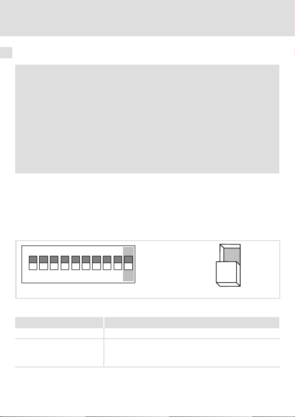
Über die frontseitigen DIP−Schalter des Funktionsmoduls lassen sich die folgenden Einstellungen komfortabel durchführen:
ƒ Software−Kompatibilität Funktionsmodul E82ZAFVC / E82ZAFD mit S10
ƒ Teilnehmeradresse mit S1 − S6
ƒ Übertragungsrate mit S7 / S8
ON
1627438
Abb. 1 Software−Kompatibilität einstellen
Kompatibilität S10
E82ZAFVC0xx OFF
E82ZAFD
Beschreibung zum Funktionsmodul: siehe Montageanleitung
E82ZAFD
22
5
910
ON
l
ON
OFF
E82ZAFD005
EDK82ZAFVC001 DE/EN/FR 2.0
Page 23
Übertragungsrate und Adresse einstellen
Übertragungsrate und Adresse einstellen
Knotenadresse einstellen
) Hinweis!
Die Teilnehmeradresse muss per Software eingestellt werden, wenn sich die
Schalter S7 und S8 in Stellung ON befinden.
In diesem Fall sind die Schalter S1 bis S6 unwirksam.
Inbetriebnahme
5
ON
1627438
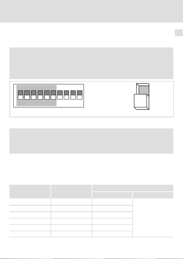
Abb. 2 Adressierung über DIP−Schalter
5
910
ON
OFF
) Hinweis!
Die Knotenadressen bei mehreren vernetzten Antriebsreglern müssen sich
voneinander unterscheiden.
Die Berechnung der Adresse (Dezimalzahl) ergibt sich durch Einsetzen des Schaltzustandes
der Schalter S1 ... S6 (’0’ = OFF und ’1’ = ON) in die folgende Gleichung:
Adresse
Aus der Gleichung lässt sich auch die Wertigkeit eines betätigten Schalters ableiten. Die
Summe der Wertigkeiten ergibt die einzustellende Knotenadresse.
Schalter Wertigkeit
S1 32 ON
S2 16 ON
S3 8 ON
S4 4 OFF
S5 2 OFF
S6 1 OFF
EDK82ZAFVC001 DE/EN/FR 2.0
= S6 · 20 + S5 · 21 + S4 · 22 + S3 · 23 + S2 · 24 + S1 · 2
dec
Schaltzustand Knotenadresse
l
5
Beispiel
32 + 16+ 8 = 56
23
Page 24
5 Inbetriebnahme
Übertragungsrate und Adresse einstellen
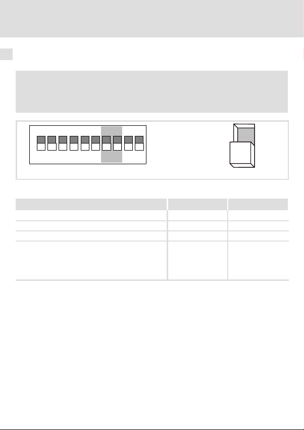
Übertragungsrate einstellen
) Hinweis!
Die Übertragungsrate muss bei allen Teilnehmern und dem Scanner identisch
sein.
ON
162743
Abb. 3 Einstellen der Übertragungsrate
Übertragungsrate S7 S8
125 kBit/s OFF OFF
250 kBit/s OFF ON
500 kBit/s ON OFF
Übertragungsrate (und Teilnehmeradresse) über Software−Konfiguration einstellen.
Die Übertragungsrate kann per Software
l manuell eingestellt werden oder
l automatisch erkannt werden.
24
85910
l
ON ON
EDK82ZAFVC001 DE/EN/FR 2.0
ON
OFF
Page 25

Inbetriebnahme
Erstes Einschalten
Erstes Einschalten
) Hinweis!
Die Beschreibung der Inbetriebnahme von Funktionsmodulen mit
DeviceNet−Kommunikationsprofil ist nicht möglich, ohne auf das für den
Betrieb des Netzwerkes notwendige Programm einzugehen.
Ein solches Programm ist nicht Teil des Lenze−Lieferumfangs.
Eine allgemeingültige Beschreibung der Inbetriebnahme des Funktionsmoduls
ist aufgrund der am Markt existierenden zahlreichen Programme nicht
möglich.
Inbetriebnahme−Schritte
) Hinweis!
Halten Sie unbedingt die Einschaltreihenfolge ein!
5
EDK82ZAFVC001 DE/EN/FR 2.0
l
25
Page 26

5 Inbetriebnahme
Schritt Vorgehensweise siehe
1. Ggf. Softwarekompatibilität einstellen
2. Knotenadresse einstellen
3. Übertragungsrate einstellen
4. Grundgerät über Klemme 28 (CINH) sperren.
Klemme 28 auf LOW−Potenzial.
Das Grundgerät kann später über den Bus gesperrt und freigegeben
werden
5. Netzspannung zuschalten
6. Separate Spannungsversorgung des Funktionsmoduls zuschalten
(DeviceNet einschalten).
Reaktion der frontseitigen LED−Anzeige:
Direkt nach dem Zuschalten der Spannungsversorgung des Funktionsmoduls leuchten die beiden frontseitigen LED’s kurzzeitig in folgender Reihenfolge auf:
l Die LED Verbindungsstatus zum Bus" wechselt ihre Farbe von grün auf
rot und erlischt dann.
l Die LED "Verbindungsstatus zum Grundgerät wechselt ihre Farbe von
grün auf rot und erlischt dann.
l Die LED Verbindungsstatus zum Bus" auf der Frontseite des Funkti-
onsmoduls blinkt (nur sichtbar beim 8200 vector).
l Die grüne LED Verbindungsstatus zum Grundgerät" auf der Frontseite
des Funktionsmoduls leuchtet (nur sichtbar beim 8200 vector).
l Keypad: dc (falls aufgesteckt)
Leitsystem für die Kommunikation mit dem Funktionsmodul mit Konfi-
7.
gurations−Software konfigurieren:
l Sie können alle Parameter vom Antrieb und/oder Funktionsmodul über
explicit messages" lesen oder schreiben.
l Sie können über die I/O−Daten Istwerte lesen (z.B. Statuswort) oder
Sollwerte schreiben (z.B. Frequenzsollwert).
Reaktion
l Die LED Verbindungsstatus zum Bus" auf der Frontseite des Funkti-
onsmoduls wechselt den Zustand Blinken auf Leuchten.
^ 22
Handbuch
des Grundgerätes
^ 16
^ 28
26
l
EDK82ZAFVC001 DE/EN/FR 2.0
Page 27

Inbetriebnahme 5
8. Prozessdaten−Kanal des Grundgerätes (siehe "Einsetzbarkeit") für den
Betrieb mit dem Funktionsmodul konfigurieren.
Empfehlung
Nach Laden der Lenze−Einstellung (C0002) Codestelle C0005 = 200 einstellen.
C0005 = 200 führt eine Vorkonfiguration für den Betrieb mit Funktionsmodul durch. Steuerwörter und Statuswörter sind dabei bereits verknüpft.
Weiter mit Schritt 12.
9. Gegebenenfalls Prozess−Ausgangsdaten des Masters/Scanners über C1511
den Eingangssignalen des Grundgerätes zuweisen.
10. Gegebenenfalls den Ausgangssignalen des Grundgerätes über C1510
Prozess−Eingangsworte des Masters/Scanners zuweisen.
11. Wenn Konfiguration in Schritt 9. oder Schritt 10. geändert wurde:
Prozess−Ausgangsdaten mit C1512 = 65535 freigeben.
12. Grundgerät über Klemme 28 (CINH) freigeben (Klemme 28 auf HIGH−Potenzial legen).
13. Sollwert über gewähltes Prozessdaten−Ausgangswort senden.
Der Antrieb läuft jetzt.
14. Grundgerät über den Bus (z.B. Steuerwort Bit 9) oder Klemme 28 (CINH)
sperren.
Schutz vor unkontrolliertem Wiederanlauf
) Hinweis!
Nach einer Störung (z. B. kurzzeitiger Netzausfall) ist der Wiederanlauf eines
Antriebs in manchen Fällen unerwünscht bzw. sogar unzulässig.
ƒ Durch Parametrieren von C0142 = 0 kann der Antrieb gesperrt werden,
wenn
– der zugehörige Antriebsregler in den Störungszustand "LU−Meldung"
übergeht und
– die Störung länger als 0,5 Sekunden aktiv ist.
Parameterfunktion:
ƒ C0142 = 0
– Der Antriebsregler bleibt gesperrt (auch wenn die Störung nicht mehr
aktiv ist) und
– der Antrieb läuft kontrolliert an: LOW−HIGH−Flanke an Klemme 28 (CINH)
ƒ C0142 = 1
– Ein unkontrollierter Anlauf des Antriebs ist möglich.
sieheVorgehensweiseSchritt
Handbuch
des Grundgerätes
^ 10
^ 10
^ 10
EDK82ZAFVC001 DE/EN/FR 2.0
l
27
Page 28

5 Inbetriebnahme
Statusanzeige
Statusanzeige
Pos Farbe Zustand Hinweise
0
1
aus Funktionsmodul wird nicht mit Spannung versorgt,
grün
blinkt Funktionsmodul ist mit Spannung versorgt, hat aber keine Verbindung
an Funktionsmodul ist mit Spannung versorgt und hat Verbindung zum
rot
blinkt Interner Fehler, Lenze−Einstellung wurde geladen
an Interner Fehler des Funktionsmodul
aus
grün
blinkt Dup_Mac_ID"−Test durchlaufen. Verbindung zum Master (Scanner)
an DeviceNet−Verbindung ist aufgebaut.
rot
blinkt Keine Kommunikation wegen Zeitüberschreitung
an Kritischer Busfehler
externe Spannungsversorgung ist ausgeschaltet
zum Antriebsregler.
Ursache:
Grundgerät ist
l abgeschaltet
l in der Initialisierungsphase
l nicht vorhanden
Grundgerät
l Verbindung zum Master nicht aufgebaut.
l Funktionsmodul wird nicht mit Spannung versorgt.
ist noch nicht aufgebaut.
E82ZAFVC001E
28
l
EDK82ZAFVC001 DE/EN/FR 2.0
Page 29

Allgemeine Daten und Einsatzbedingungen
Technische Daten
6 Technische Daten
Allgemeine Daten und Einsatzbedingungen
Bereich Werte
Kommunikationsprofil DeviceNet
Kommunikationsmedium DIN ISO 11898
Netzwerk−Topologie Beidseitig abgeschlossene Linie (R = 120 Ohm)
Max. Anzahl Teilnehmer 63
DeviceNet−Teilnehmer Slave
Übertragungsrate [kBit/s] 125, 250, 500
Erreichbare Busleitungslänge Abhängig vom verwendeten Kabel, siehe ^ 20
Externe Spannungsversorgung siehe ^ 16
Umgebungsbedingungen
Klimatische Bedingungen
Lagerung 1 K3 nach IEC/EN 60721−3−1 − 25 ... + 60 °C
Transport 2 K3 nach IEC/EN 60721−3−2 − 25 ... + 70 °C
Betrieb 3 K3 nach IEC/EN 60721−3−3 − 20 ... + 60 °C
Verschmutzungsgrad 2 nach IEC/EN 61800−5−1
Schutzart IP20
Anschlüsse
X3/
V+
7 Bezugspotenzial 1
39 Bezugspotenzial 2 der Reglersperre (CINH) an X3/28
28 Reglersperre
20 + 20 V intern für CINH, Bezugspotenzial 1, Belastbarkeit: I
Externe DC−Spannungsversorgung des Funktionsmoduls:
+24 V DC ±10 %, max. 80 mA
Der beim Durchschleifen der Versorgungsspannung zu anderen Busteilnehmern über die Klemme V+ fließende Strom darf
max. 3 A betragen.
l Start = HIGH (+12 V ... +30 V)
l Stop = LOW (0 V ... +3 V)
Eingangswiderstand: 3.3 kW
30 mA
max
6
=
EDK82ZAFVC001 DE/EN/FR 2.0
l
29
Page 30

6 Technische Daten
Schutzisolierung
Schutzisolierung
Schutzisolierung zwischen Bus und ... Art der Isolierung (nach EN 61800−5−1)
l Bezugserde / PE (X3/SH)
l externer Versorgung (X3/V+)
l Versorgung für CINH (X3/20)
l Reglersperre, CINH (X3/28)
l Leistungsteil
– 8200 vector verstärkte Isolierung
– 8200 motec verstärkte Isolierung
– starttec verstärkte Isolierung
l Steuerklemmen
– 8200 vector Betriebsisolierung
– 8200 motec Betriebsisolierung
Betriebsisolierung
keine Potenzialtrennung
keine Potenzialtrennung
Betriebsisolierung
30
l
EDK82ZAFVC001 DE/EN/FR 2.0
Page 31

Abmessungen
alle Maße in mm
Technische Daten
Abmessungen
E82ZAFD001E
6
EDK82ZAFVC001 DE/EN/FR 2.0
l
31
Page 32

Legend for fold−out page See
Status display (two−colour green / red), connection to the standard device
0
Status display (two−colour green / red), connection to the bus
1
DIP switches for setting
2
l Node address ("Address")
l Baud rate ("Bd")
l Compatibility with Lenze function module E82ZAFD (DeviceNet)
Terminal strip X3, connections for
3
l DeviceNet
l Controller inhibit (CINH)
l External voltage supply (via DeviceNet cable)
Nameplate ^ 33
4
0Fig. 0Tab. 0
I Tip!
Current documentation and software updates concerning Lenze products can
be found on the Internet in the "Services & Downloads" area under
http://www.Lenze.com
^ 56
^ 50
^ 47
32
l
EDK82ZAFVC001 DE/EN/FR 2.0
Page 33

Validity
APPLICATION
010 / 3A22
These instructions are valid for
ƒ E82ZAFVC001 function modules, DeviceNet, as of version Vx.0x.
These instructions are only valid together with the Operating Instructions for the standard
devices permitted for the application.
Identification
APPLICATION
010/ 3A22
L
Type
Id.-No.
Prod.-No.
Ser.-No.
E82AF000P0B201XX
E82ZAFX005
Type code E82ZAF V C 001 Vx 0x
Series
DeviceNet
Generation
Variant 001: coated design
Hardware version
Software version
Order designation
E82ZAFVC001Vx0x
Function
The function module connects Lenze controllers to the serial communication system
DeviceNet.
EDK82ZAFVC001 DE/EN/FR 2.0
l
33
Page 34

Application range
The function module E82ZAFVC001 can be used with the
following standard devices
Frequency inverter 8200 vector Vx14
8200 motec Vx14
Motor starter starttec Vx1x
as of version
34
l
EDK82ZAFVC001 DE/EN/FR 2.0
Page 35

Contents i
1 Safety instructions 36 . . . . . . . . . . . . . . . . . . . . . . . . . . . . . . . . . . . . . . . . . . . . . . . . . . .
Definition of notes used 36 . . . . . . . . . . . . . . . . . . . . . . . . . . . . . . . . . . . . . . . . . . . . . .
Residual hazards 37 . . . . . . . . . . . . . . . . . . . . . . . . . . . . . . . . . . . . . . . . . . . . . . . . . . . . .
2 Scope of supply 38 . . . . . . . . . . . . . . . . . . . . . . . . . . . . . . . . . . . . . . . . . . . . . . . . . . . . . .
3 Mechanical installation 39 . . . . . . . . . . . . . . . . . . . . . . . . . . . . . . . . . . . . . . . . . . . . . . .
4 Electrical installation 40 . . . . . . . . . . . . . . . . . . . . . . . . . . . . . . . . . . . . . . . . . . . . . . . . .
Wiring according to EMC 40 . . . . . . . . . . . . . . . . . . . . . . . . . . . . . . . . . . . . . . . . . . . . . .
Wiring 41 . . . . . . . . . . . . . . . . . . . . . . . . . . . . . . . . . . . . . . . . . . . . . . . . . . . . . . . . . . . . .
5 Commissioning 49 . . . . . . . . . . . . . . . . . . . . . . . . . . . . . . . . . . . . . . . . . . . . . . . . . . . . .
Before switching on 49 . . . . . . . . . . . . . . . . . . . . . . . . . . . . . . . . . . . . . . . . . . . . . . . . .
Setting options via switches 50 . . . . . . . . . . . . . . . . . . . . . . . . . . . . . . . . . . . . . . . . . . .
Setting the baud rate and address 51 . . . . . . . . . . . . . . . . . . . . . . . . . . . . . . . . . . . . . .
Initial switch−on 53 . . . . . . . . . . . . . . . . . . . . . . . . . . . . . . . . . . . . . . . . . . . . . . . . . . . . .
Status display 56 . . . . . . . . . . . . . . . . . . . . . . . . . . . . . . . . . . . . . . . . . . . . . . . . . . . . . . .
6 Technical data 57 . . . . . . . . . . . . . . . . . . . . . . . . . . . . . . . . . . . . . . . . . . . . . . . . . . . . . . .
General data and operating conditions 57 . . . . . . . . . . . . . . . . . . . . . . . . . . . . . . . . . .
Protective insulation 58 . . . . . . . . . . . . . . . . . . . . . . . . . . . . . . . . . . . . . . . . . . . . . . . . .
Dimensions 59 . . . . . . . . . . . . . . . . . . . . . . . . . . . . . . . . . . . . . . . . . . . . . . . . . . . . . . . . .
EDK82ZAFVC001 DE/EN/FR 2.0
l
35
Page 36

1 Safety instructions
Definition of notes used
1 Safety instructions
Definition of notes used
The following pictographs and signal words are used in this documentation to indicate
dangers and important information:
Safety instructions
Structure of safety instructions:
} Danger!
(characterises the type and severity of danger)
Note
(describes the danger and gives information about how to prevent dangerous
situations)
Pictograph and signal word Meaning
Danger of personal injury through dangerous electrical
voltage.
{ Danger!
} Danger!
( Stop!
Application notes
Pictograph and signal word Meaning
Reference to an imminent danger that may result in death
or serious personal injury if the corresponding measures are
not taken.
Danger of personal injury through a general source of
danger.
Reference to an imminent danger that may result in death
or serious personal injury if the corresponding measures are
not taken.
Danger of property damage.
Reference to a possible danger that may result in property
damage if the corresponding measures are not taken.
) Note!
I Tip!
,
36
Important note to ensure troublefree operation
Useful tip for simple handling
Reference to another documentation
l
EDK82ZAFVC001 DE/EN/FR 2.0
Page 37

Residual hazards
} Danger!
Observe the safety instructions and residual hazards included in the
instructions for the standard device.
Safety instructions
Residual hazards
1
EDK82ZAFVC001 DE/EN/FR 2.0
l
37
Page 38

2 Scope of supply
2 Scope of supply
8
9
:
Pos. Item Info
Function module E82ZAFVC001
Mounting Instructions
Screw driver
8
9 Two bus terminating resistors (120 W each)
Adhesive tape
:
I Tip!
In addition to these Mounting Instructions we provide further information on
this function module on the URL given on page 4.
E82ZAFX028/E82ZAFD001E
^ 40
38
l
EDK82ZAFVC001 DE/EN/FR 2.0
Page 39

Mechanical installation 3
3 Mechanical installation
Follow the notes given in the Mounting Instructions for the standard device for the
mechanical installation of the function module.
The Mounting Instructions for the standard device
ƒ are part of the scope of supply and are enclosed with each device.
ƒ provide tips for avoiding damage through improper handling.
ƒ describe the obligatory order of installation steps.
EDK82ZAFVC001 DE/EN/FR 2.0
l
39
Page 40

4 Electrical installation
Wiring according to EMC
4 Electrical installation
Wiring according to EMC
Please observe the following for wiring according to EMC guidelines:
) Note!
ƒ Separate control cables from motor cables.
ƒ Connect the shields of the control cables and data cables on both sides.
The shield for the function module must be connected to the terminal "SH"
(Shield).
ƒ Differences in potential between the standard devices can be avoided by
using an equalizing conductor with a large cross−section (reference: PE).
ƒ Please see the information on wiring according to EMC guidelines in the
Operating Instructions for the standard device.
General wiring information
1. Comply with the DeviceNet bus topology
2.
Bus terminating resistors of 120 W each (scope of delivery):
l between CAN−LOW and CAN−HIGH
l only at the cable ends
3. Bus cable according to the specification ^ 42.
4. Do not exceed the permissible bus cable length (see ^ 48).
40
l
EDK82ZAFVC001 DE/EN/FR 2.0
Page 41

Electrical installation
123 456789 10
123 456789 10
Wiring
Wiring to a host
The following figure shows the cable routing for the function module:
Wiring
4
Adress
V-
CL
SHCHV+
D
Bd
V
V-
SH
20
CL
CH V+
39
7
28
DeviceNet
D
Adress
Bd
V
20
39
7
V-
CL
SHCHV+
V-
SH
20
CL
CH V+
39
7
28
28
V-
CL
SH
V+
CH
V-
20
39
7
28
CL
SH
V+
CH
DeviceNet
E82ZAFD019 E82ZAFD102
For integrating the function modules a PC with installed configuration software is used.
EDK82ZAFVC001 DE/EN/FR 2.0
l
41
Page 42

4 Electrical installation
Specification of the transmission cable
The devices are connected to the bus system using a fieldbus cable according to the
DeviceNet
Companies like Belden Wire & Cable, Olflex Wire & Cable, C&M Corp. and Madison Cable
produce DeviceNet
TM
specification (DeviceNet Adaption of CIP, Edition 1.1, Volume Three).
TM
Thick" and Thin" cables.
) Note!
Use the Thin" cable to wire the function module ^ 42.
Features of the Thin" cable according to DeviceNet specifications
General features
Configuration Two shielded symmetrical cables with a common axis and drain wire in
Total shielding 65% coverage
Drain wire Copper 22 min.; min. 19 cores (individually tinned)
Outer diameter 6.096 mm (min.) to 7.112 mm (max.)
Roundness Radius deviation must be within 20% of 0.5 outer diameter
Jacket marking Vendor name & part no. and additional markings
Spec. DC resistor (braid, tape, drain) 10.5 Ohm/1000 m (nominal at 20°C)
Certifications (U.S. and Canada) NEC (UL), CL2 (min.)
Bend radius 20 x diameter (installation) / 7 x diameter (fixed)
Ambient operating temperature −20°C to +70°C at 1.5 Ampere; derate current linearly to zero at 80°C
Storage temperature −40°C to +85°C
Pull tension 289.23 N
the centre
AWG 36 or min. 0.12 mm tinned braid (individually tinned)
max
42
l
EDK82ZAFVC001 DE/EN/FR 2.0
Page 43

Electrical installation 4
Features of the data line
Insulation diameter 1.96 mm (nominal)
Conductor pair Copper 24 min.; min. 19 cores (individually tinned)
Colours Light−blue, white
Pair twist / m Approx. 16
Tape shield over conductor pair 1000/1000, Al/Mylar, Al side out, w−shorting fold (pull−on applied)
Impedance 120 Ohm +/− 10% (at 1 MHz)
Propagation delay 4.46 ns/m (max.)
Capacitance between conductors 39.37 pF / m at 1 kHz (nominal)
Capacitance between a condcutor and the
conductor connected to the shield
Capacitive unbalance 3.94 pF/1000 m at 1 kHz (max.)
Spec. DC resistor at 20°C 91.86 Ohm/1000 m (max.)
Attenuation 0.95 dB/100 m at 125 kHz (max.)
Features of the voltage line
Conductor pair Copper 22 min.; min. 19 cores (individually tinned)
Insulation diameter 1.4 mm (nominal)
Colours Red, black
Pair twist / m Approx. 16
Tape shield over conductor pair 1000/1000, Al/Mylar, Al side out, w−shorting fold (pull−on applied)
Spec. DC resistor at 20°C 57.41 Ohm/1000 m (max.)
78.74 pF / m at 1 kHz (nominal)
1.64 dB/100 m at 500 kHz (max.)
2.30 dB/100 m at 1.00MHz (max.)
EDK82ZAFVC001 DE/EN/FR 2.0
l
43
Page 44

4 Electrical installation
Terminal data
Electrical connection Terminal strip with screw connection
Possible connections
Tightening torque 0.22 ... 0.25 Nm (1.9 ... 2.2 lb−in)
Bare end 5 mm
rigid: 1.5 mm
flexible:
without wire end ferrule
1.0 mm
with wire end ferrule, without plastic sleeve
0.5 mm
with wire end ferrule, with plastic sleeve
0.5 mm
2
2
(AWG 18)
2
(AWG 20)
2
(AWG 20)
(AWG 16)
External voltage supply
) Note!
DeviceNet communication modules from Lenze are only supplied via the
external DeviceNet cable!
44
l
EDK82ZAFVC001 DE/EN/FR 2.0
Page 45

Internal wiring of the bus terminals
V
cc
V
cc
3
5
1
4
8
7
6
2
Electrical installation 4
V+
CAN-HIGH
Shield
CAN-LOW
V-
2175DeN007
EDK82ZAFVC001 DE/EN/FR 2.0
l
45
Page 46

4 Electrical installation
Supply of the controller inhibit (CINH) via the internal voltage source (X3/20)
GND1
GND2
28397
X3
SH SHCH CH
CLCLV-
_
V+ V+
V-
20
+
Supply of the controller inhibit (CINH) via the external voltage source
GND1
GND2
28397
20
_
+
46
X3
SH SHCH CH
CLCLV-
_
V+ V+
+
V-
Min. wiring required for operation
l
E82ZAFD003
E82ZAFD006
EDK82ZAFVC001 DE/EN/FR 2.0
Page 47

Electrical installation 4
Name Function Level
X3/
V− Reference potential for external voltage supply
CL CAN−LOW CAN data line (LOW)
SH SHIELD Shield
CH CAN−HIGH CAN data line (HIGH)
V+ External supply voltage Please observe notes concerning
7 GND1 Reference potential for X3/20
39 GND2 Reference potential for controller inhibit (CINH) at X3/28
28 CINH Controller inhibit
20 DC voltage supply for internal supply of
controller inhibit (CINH)
external supply!
l Start = HIGH (+12 V ... +30 V)
l Stop = LOW (0 ... +3 V)
+20 V (ref.: GND1)
EDK82ZAFVC001 DE/EN/FR 2.0
l
47
Page 48

4 Electrical installation
Max. possible bus cable length
The following bus cable lengths are possible in dependence on the baud rate and the cable
used:
Baud rate Thin Cable Thick Cable
125 kbits/s
250 kbits/s 250 m
500 kbits/s 100 m
When using both, Thick" and Thin" cables, the maximum cable lengths are to be selected
according to the baud rate:
Baud rate Bus cable length
125 kbits/s L
250 kbits/s L
500 kbits/s L
100 m
= 500 m = L
max
= 250 m = L
max
= 100 m = L
max
thick
thick
thick
+ 5 L
+ 2.5 L
+ L
thin
500 m
thin
thin
48
l
EDK82ZAFVC001 DE/EN/FR 2.0
Page 49

Commissioning
Before switching on
5 Commissioning
Before switching on
( Stop!
Before you switch on the standard device with the communication module for
the first time, check
ƒ the entire wiring for completeness, short circuit and earth fault.
ƒ whether the bus system is terminated through the bus terminating
resistor at the first and last physical bus station.
5
EDK82ZAFVC001 DE/EN/FR 2.0
l
49
Page 50

5 Commissioning
Setting options via switches
Setting options via switches
) Note!
Settings via GDC, operating module or configuration software
The settings of device address and baud rate via GDC, the operating module or
the configuration software only become valid when the DIP switches S7 and S8
are in the "ON" position.
Settings via front switch
The Lenze setting of all switches is OFF.
The device address and baud rate set via DIP switch will only be active after a
renewed mains connection.
The switch S9 is ineffective.
The following settings can be easily carried out via the front DIP switch of the function
module:
ƒ Software compatibility of E82ZAFVC / E82ZAFD function module with S10
ƒ Device address with S1 − S6
ƒ Baud rate with S7 / S8
ON
1627438
Fig. 1 Software compatibility setting
Compatibility S10
E82ZAFVC0xx OFF
E82ZAFD
For the description of the
function module see the
E82ZAFD Mounting Instructions
5
910
ON
50
l
ON
OFF
E82ZAFD005
EDK82ZAFVC001 DE/EN/FR 2.0
Page 51

Setting the baud rate and address
Setting the baud rate and address
Node address setting
) Note!
The device address must be set via software, when the switches S7 and S8 are
in ON position.
In this case the switches S1 to S6 are ineffective.
Commissioning
5
ON
1627438
Fig. 2 Address assignment via DIP switch
5
910
ON
OFF
) Note!
If several controllers are connected to the network, the node addresses must
differ from each other.
The address (decimal number) is calculated by inserting the positions of switches S1 to S6
(’0’ = OFF and ’1’ = ON) into the following equation.
Address
The equation can also be used to calculate the valency of a switch. The sum of valencies
results in the node address to be set:
Switch Valency
S1 32 ON
S2 16 ON
S3 8 ON
S4 4 OFF
S5 2 OFF
S6 1 OFF
EDK82ZAFVC001 DE/EN/FR 2.0
= S6 · 20 + S5 · 21 + S4 · 22 + S3 · 23 + S2 · 24 + S1 · 2
dec
Switch position Node address
l
5
Example
32 + 16+ 8 = 56
51
Page 52

5 Commissioning
Setting the baud rate and address
Baud rate setting
) Note!
The baud rate must be the same for all devices and the scanner.
ON
162743
Fig. 3 Baud rate setting
Baud rate S7 S8
125 kbits/s OFF OFF
250 kbits/s OFF ON
500 kbits/s ON OFF
Setting of baud rate (and node address) via software
configuration.
The baud rate can be
l set manually via software or
l automatically detected.
52
85910
l
ON ON
EDK82ZAFVC001 DE/EN/FR 2.0
ON
OFF
Page 53

Commissioning
Initial switch−on
Initial switch−on
) Note!
The commissioning of function modules with DeviceNet communication
profile cannot be described without going into the program required for the
network operation.
Such a program is not included in the Lenze delivery scope.
Due to the large number of programs available in the market, it is not possible
to give a universal description for the commissioning of the function module.
Step−by−step commissioning
) Note!
Keep to the switch−on sequence!
5
EDK82ZAFVC001 DE/EN/FR 2.0
l
53
Page 54

5 Commissioning
Step Procedure see
1. If necessary, set the software compatibility
2. Set the node address
3. Set the baud rate
4. Inhibit the standard device via terminal 28 (CINH).
Terminal 28 on LOW potential.
The standard device can be inhibited and enabled via the bus
5. Connect mains voltage
6. Connect the separate voltage supply for the function module
(Switch on the DeviceNet).
Response of the front LED display:
Directly after the voltage supply for the function module has been
connected, both LEDs at the front light up for a short time in the following
order:
l The LED Status of connection with bus" changes its colour from green
to red before it goes off.
l The LED "Status of the connection to the standard device" changes its
colour from green to red before it goes off.
l The LED Connection status to the bus" at the front of the function
module is blinking (only visible in case of 8200 vector).
l The green LED Status of connection with standard device" at the front
of the function module is on (only visible in case of 8200 vector).
l Keypad: dc(if attached)
7.
Configure the host system for communicating with the function module
with configuration software:
l With explicit messages" all parameters can be read or written from
the drive and/or function module.
l Actual values can be read (e.g. status word) or setpoints can be written
(e.g. frequency setpoint) via the I/O data.
Response
l The LED Status of connection with the bus" at the front of the
function module changes from blinking to the constantly ON state.
^ 50
^ 44
^ 56
Manual of
the standard
device
54
l
EDK82ZAFVC001 DE/EN/FR 2.0
Page 55

Commissioning 5
8. Configure process data channel of the standard device (see "application
range") for operation with the function module.
Recommendation
Set code C0005 = 200 after the Lenze setting has been loaded (C0002).
C0005 = 200 preconfigures the device for the operation with a function
module. Control and status words are already linked.
Continue with step 12.
9. If required, assign the process output data of the master/scanner via
C1511 to the input signals of the standard device.
10. If required, assign the process input words of the master/scanner to the
output signals of the standard device via C1510.
11. If the configuration in step 9. or step 10. has been changed:
Enable process output data with C1512 = 65535.
12. Enable standard device with terminal 28 (CINH) (terminal 28 on HIGH).
13. Send setpoint via a selected process data output word.
The drive is now running.
14. Inhibit the standard device via the bus (e.g. control word bit 9) or terminal
28 (CINH).
Protection against uncontrolled restart
) Note!
In some cases the controller should not restart after a fault (e.g. after a short
mains failure).
ƒ The drive can be inhibited by setting C0142 = 0 if
– the corresponding controller sets a fault "LU message" and
– the fault is active for more than 0.5 seconds.
Parameter function:
ƒ C0142 = 0
– The controller remains inhibited even after the fault has been
eliminated and
– the drive restarts in a controlled mode: LOW−HIGH transition at terminal
28 (CINH)
ƒ C0142 = 1
– An uncontrolled restart of the controller is possible.
seeProcedureStep
Manual of
the standard
device
^ 38
^ 38
^ 38
EDK82ZAFVC001 DE/EN/FR 2.0
l
55
Page 56

5 Commissioning
Status display
Status display
Pos Colour Status Notes
0
1
OFF Function module is not supplied with voltage,
GREEN
BLINKING Function module is supplied with voltage but not connected to the
ON Function module is supplied with voltage and is connected to the
RED
BLINKING Internal error, Lenze setting has been loaded
ON Internal error of the function module
OFF
GREEN
BLINKING Dup_Mac_ID" test phase. Not yet connected to master (scanner).
ON DeviceNet connection established.
RED
BLINKING No communication because time limit has been exceeded
ON Critical bus error
external voltage supply is switched off
controller.
Reason:
Standard device is
l switched off
l is being initialised
l not available
standard device
l No connection to the master
l Function module is not supplied with voltage.
E82ZAFVC001E
56
l
EDK82ZAFVC001 DE/EN/FR 2.0
Page 57

General data and operating conditions
Technical data
6 Technical data
General data and operating conditions
Field Values
Communication profile DeviceNet
Communication medium DIN ISO 11898
Network topology Line terminated at both ends (R = 120 Ohms)
Max. number of devices 63
DeviceNet device Slave
Baud rate [kbit/s] 125, 250, 500
Achievable bus cable length Depending on the cable used, see ^ 48
External voltage supply See ^ 44
Ambient conditions
Climatic conditions
Storage 1 K3 acc. to IEC/EN 60721−3−1 − 25 ... + 60 °C
Transport 2 K3 acc. to IEC/EN 60721−3−2 − 25 ... + 70 °C
Operation 3 K3 acc. to IEC/EN 60721−3−3 − 20 ... + 60 °C
Degree of pollution 2 acc. to IEC/EN 61800−5−1
Enclosure IP20
Connections
X3/
V+
7 Reference potential 1
39 Reference potential 2 of the controller inhibit (CINH) at X3/28
28 Controller inhibit
20 + 20 V internal for CINH, reference potential 1, load capacity:
External DC voltage supply of the function module:
+24 V DC ±10 %, max. 80 mA
The current flowing via terminal V+ during looping through of
the supply voltage to other devices, is to amount to a
maximum of 3 A.
l Start = HIGH (+12 V ... +30 V)
l Stop = LOW (0 V ... +3 V)
Input resistance: 3.3 kW
I
= 30 mA
max
6
EDK82ZAFVC001 DE/EN/FR 2.0
l
57
Page 58

6 Technical data
Protective insulation
Protective insulation
Protective insulation between bus and ... Type of insulation (acc. to EN 61800−5−1)
l reference earth / PE (X3/SH)
l external supply (X3/V+)
l supply for CINH (X3/20)
l controller inhibit, CINH (X3/28)
l power section
– 8200 vector Reinforced insulation
– 8200 motec Reinforced insulation
– starttec Reinforced insulation
l control terminals
– 8200 vector Functional insulation
– 8200 motec Functional insulation
Functional insulation
No electrical isolation
No electrical isolation
Functional insulation
58
l
EDK82ZAFVC001 DE/EN/FR 2.0
Page 59

Dimensions
All dimensions in mm
Technical data
Dimensions
E82ZAFD001E
6
EDK82ZAFVC001 DE/EN/FR 2.0
l
59
Page 60

Légende de l’illustration de la page dépliante Voir
Affichage d’état (bicolore vert / rouge), liaison avec l’appareil de base
0
Affichage d’état (bicolore vert / rouge), liaison avec le bus
1
Interrupteur DIP pour le réglage de
2
l l’adresse du noeud ("Adress"),
l la vitesse de transmission ("Bd"),
l la compatibilité avec le module de fonction Lenze E82ZAFD (DeviceNet).
Bornier X3, raccordements pour
3
l DeviceNet,
l blocage variateur (CINH),
l alimentation externe (via câble DeviceNet)
Plaque signalétique ^ 61
4
0Fig. 0Tab. 0
I Conseil !
Les mises à jour de logiciels et les documentations récentes relatives aux
produits Lenze sont disponibles dans la zone "Téléchargements" du site
Internet :
http://www.Lenze.com
^ 84
^ 78
^ 75
60
l
EDK82ZAFVC001 DE/EN/FR 2.0
Page 61

Validité
APPLICATION
010 / 3A22
Le présent document s’applique aux modules suivants :
ƒ modules de fonction E82ZAFVC001, DeviceNet, à partir de la version Vx.0x.
Ce document est uniquement valable avec la documentation relative aux appareils de base
compatibles.
Identification
APPLICATION
010/ 3A22
L
Type
Id.-No.
Prod.-No.
Ser.-No.
E82AF000P0B201XX
E82ZAFX005
Codification des types E82ZAF V C 001 Vx 0x
Série d’appareils
DeviceNet
Génération d’appareils
Variante 001 : version vernie
Version matérielle
Version logicielle
Référence de commande
E82ZAFVC001Vx0x
Fonction
Le module de fonction permet de relier les variateurs de vitesse Lenze au système de
communication DeviceNet.
EDK82ZAFVC001 DE/EN/FR 2.0
l
61
Page 62

Utilisation
Le module de fonction E82ZAFVC001 peut être utilisé avec les
appareils de base suivants :
Convertisseur de fréquence 8200 vector Vx14
8200 motec Vx14
Démarreur moteur starttec Vx1x
A partir de la version
62
l
EDK82ZAFVC001 DE/EN/FR 2.0
Page 63

Sommaire i
1 Consignes de sécurité 64 . . . . . . . . . . . . . . . . . . . . . . . . . . . . . . . . . . . . . . . . . . . . . . . .
Définition des conventions utilisées 64 . . . . . . . . . . . . . . . . . . . . . . . . . . . . . . . . . . . . .
Dangers résiduels 65 . . . . . . . . . . . . . . . . . . . . . . . . . . . . . . . . . . . . . . . . . . . . . . . . . . .
2 Equipement livré 66 . . . . . . . . . . . . . . . . . . . . . . . . . . . . . . . . . . . . . . . . . . . . . . . . . . . .
3 Installation mécanique 67 . . . . . . . . . . . . . . . . . . . . . . . . . . . . . . . . . . . . . . . . . . . . . . .
4 Installation électrique 68 . . . . . . . . . . . . . . . . . . . . . . . . . . . . . . . . . . . . . . . . . . . . . . . .
Câblage conforme CEM 68 . . . . . . . . . . . . . . . . . . . . . . . . . . . . . . . . . . . . . . . . . . . . . . .
Câblage 69 . . . . . . . . . . . . . . . . . . . . . . . . . . . . . . . . . . . . . . . . . . . . . . . . . . . . . . . . . . . .
5 Mise en service 77 . . . . . . . . . . . . . . . . . . . . . . . . . . . . . . . . . . . . . . . . . . . . . . . . . . . . . .
Avant la première mise sous tension 77 . . . . . . . . . . . . . . . . . . . . . . . . . . . . . . . . . . . .
Réglages via interrupteurs 78 . . . . . . . . . . . . . . . . . . . . . . . . . . . . . . . . . . . . . . . . . . . . .
Réglage de la vitesse de transmission et de l’adresse 79 . . . . . . . . . . . . . . . . . . . . . .
Première mise en service 81 . . . . . . . . . . . . . . . . . . . . . . . . . . . . . . . . . . . . . . . . . . . . . .
Affichage d’état 84 . . . . . . . . . . . . . . . . . . . . . . . . . . . . . . . . . . . . . . . . . . . . . . . . . . . . .
6 Spécifications techniques 85 . . . . . . . . . . . . . . . . . . . . . . . . . . . . . . . . . . . . . . . . . . . . .
Caractéristiques générales et conditions d’utilisation 85 . . . . . . . . . . . . . . . . . . . . . .
Isolement de protection 86 . . . . . . . . . . . . . . . . . . . . . . . . . . . . . . . . . . . . . . . . . . . . . . .
Encombrements 87 . . . . . . . . . . . . . . . . . . . . . . . . . . . . . . . . . . . . . . . . . . . . . . . . . . . . .
EDK82ZAFVC001 DE/EN/FR 2.0
l
63
Page 64

1 Consignes de sécurité
Définition des conventions utilisées
1 Consignes de sécurité
Définition des conventions utilisées
Pour indiquer des risques et des informations importantes, la présente documentation
utilise les mots et symboles suivants :
Consignes de sécurité
Présentation des consignes de sécurité
} Danger !
(Le pictogramme indique le type de risque.)
Explication
(L’explication décrit le risque et les moyens de l’éviter.)
Pictogramme et mot associé Explication
Situation dangereuse pour les personnes en raison d’une
tension électrique élevée
{ Danger !
} Danger !
( Stop !
Consignes d’utilisation
Pictogramme et mot associé Explication
Indication d’un danger imminent qui peut avoir pour
conséquences des blessures mortelles ou très graves en cas
de non−respect des consignes de sécurité correspondantes
Situation dangereuse pour les personnes en raison d’un
danger d’ordre général
Indication d’un danger imminent qui peut avoir pour
conséquences des blessures mortelles ou très graves en cas
de non−respect des consignes de sécurité correspondantes
Risques de dégâts matériels
Indication d’un risque potentiel qui peut avoir pour
conséquences des dégâts matériels en cas de non−respect
des consignes de sécurité correspondantes
) Remarque
importante !
I Conseil !
,
64
Remarque importante pour assurer un fonctionnement
correct
Conseil utile pour faciliter la mise en oeuvre
Référence à une autre documentation
l
EDK82ZAFVC001 DE/EN/FR 2.0
Page 65

Consignes de sécurité
Dangers résiduels
Dangers résiduels
} Danger !
Tenir compte des consignes de sécurité et des dangers résiduels décrits dans la
documentation de l’appareil de base concerné.
1
EDK82ZAFVC001 DE/EN/FR 2.0
l
65
Page 66

2 Equipement livré
2 Equipement livré
8
9
:
E82ZAFX028/E82ZAFD001E
Pos. Elément Information
Module de fonction E82ZAFVC001
Instructions de montage
Tournevis
8
9 Deux résistances d’extrémité de bus (120 W chacune)
Bande autocollante
:
^ 68
I Conseil !
En complément de ces instructions de montage, vous trouverez à l’adresse
Internet indiquée à la page 4 de plus amples informations concernant ce
module de fonction.
66
l
EDK82ZAFVC001 DE/EN/FR 2.0
Page 67

Installation mécanique 3
3 Installation mécanique
Pour l’installation mécanique du module de fonction, suivre les consignes fournies dans les
instructions de montage de l’appareil de base.
Les instructions de montage de l’appareil de base
ƒ font partie de la livraison standard et sont comprises dans l’emballage,
ƒ contiennent des consignes pour éviter des dommages dus à un emploi
contre−indiqué,
ƒ décrivent l’ordre à respecter pour les opérations d’installation.
EDK82ZAFVC001 DE/EN/FR 2.0
l
67
Page 68

4 Installation électrique
Câblage conforme CEM
4 Installation électrique
Câblage conforme CEM
Pour s’assurer que le câblage est conforme aux exigences à respecter en matière de CEM,
vérifier les points suivants :
) Remarque importante !
ƒ Séparer physiquement les câbles de commande des câbles moteur.
ƒ Blinder les câbles de commande et de données aux deux extrémités. La
borne "SH" (Shield) est prévue pour la reprise du blindage sur le module de
fonction.
ƒ Prévoir une ligne de compensation de section importante (référence : PE)
afin d’éviter les différences de potentiel entre les appareils de base des
différents participants.
ƒ Tenir compte des autres indications contenues dans la documentation des
appareils de base sur un câblage conforme aux exigences à respecter en
matière de CEM.
Remarques générales concernant le câblage
1. Respecter la topologie de bus DeviceNet
2.
Connecter des résistances d’extrémité de bus de 120 W chacune (équipement livré) :
l entre CAN−LOW et CAN−HIGH.
l uniquement au niveau du premier et du dernier participant.
3. Utiliser un câble bus conforme à la spécification ^ 70.
4. Respecter la longueur de câble bus autorisée (voir ^ 76).
68
l
EDK82ZAFVC001 DE/EN/FR 2.0
Page 69

Installation électrique
123 456789 10
123 456789 10
Câblage
Raccordement au maître
La figure ci−dessous illustre la conduite de câble sur le module de fonction :
Câblage
4
Adress
V-
CL
SHCHV+
D
Bd
V
V-
SH
20
CL
CH V+
39
7
28
DeviceNet
D
Adress
Bd
V
20
39
7
V-
CL
SHCHV+
V-
SH
20
CL
CH V+
39
7
28
28
V-
CL
SH
V+
CH
V-
20
39
7
28
CL
SH
V+
CH
DeviceNet
E82ZAFD019 E82ZAFD102
L’intégration des modules de fonction s’effectue à l’aide d’un PC avec logiciel de
configuration installé.
EDK82ZAFVC001 DE/EN/FR 2.0
l
69
Page 70

4 Installation électrique
Spécifications du câble de transmission
La liaison des participants au bus est réalisée à l’aide d’un câble bus de terrain selon la
spécification DeviceNet
sociétés telles que Belden Wire & Cable, Olflex Wire & Cable, C&M Corp. et Madison Cable
fabriquent des câbles DeviceNet
TM
(DeviceNet Adaption of CIP, Edition 1.1, Volume Three). Des
TM
Thick" et Thin".
) Remarque importante !
Pour le câblage du module de fonction, utiliser le câble mince
(Thin Cable) ^ 70.
Caractéristiques du Thin Cable" (câble mince) conformément aux spécifications
DeviceNet
Caractéristiques générales
Configuration Deux câbles blindés symétriques, axe commun avec fil de mise à la
Blindage total Couverture 65 %
Fil de mise à la terre Cuivre 22 minimum ; 19 brins minimum (étamés séparément)
Diamètre extérieur 6,096 mm (mini) à 7,112 mm (maxi)
Cylindricité L’écart de rayon ne peut être supérieur à 20 % de la moitié du diamètre
Inscriptions sur la gaine Nom du vendeur, n° de pièce et autres inscriptions
Résistance CC spéc. (tressage, embobinage,
dérivation)
Homologations (Etats−Unis et Canada) NEC (UL), CL2 (mini)
Rayon de courbure 20 x diamètre (installation) / 7 x diamètre (fixe)
Température ambiante − fonctionnement −20 °C ... +70 °C à 1,5 A ; à 80 °C, réduction progressive du courant
Température de stockage −40 °C ... +85 °C
Traction 289,23 N
terre au centre
AWG 36 ou tresse en cuivre étamée de 0,12 mm minimum (fils étamés
séparément)
extérieur.
10,5 ohms/1000 m (nom. à 20 °C)
jusqu’à zéro
maxi
70
l
EDK82ZAFVC001 DE/EN/FR 2.0
Page 71

Installation électrique 4
Caractéristiques du câble de données
Diamètre d’isolation 1,96 mm (nom.)
Paire de conducteurs Cuivre 24 minimum ; 19 brins minimum (étamés séparément)
Couleurs Bleu clair, blanc
Nombre de spires / m Environ 16
Blindage par paire de conducteurs 1000/1000, Al/Mylar, feuille Al à l’extérieur, dispositif de mise en
Impédance 120 ohms +/− 10 % (à 1 MHz)
Vitesse de propagation 4,46 ns/m (maxi)
Capacité entre conducteurs 39,37 pF / m à 1 kHz (nom.)
Capacité entre un conducteur et un autre relié
au blindage
Asymétrie capacitive 3,94 pF/1000 m à 1 kHz (maxi)
Résistance CC spéc. à 20 °C 91,86 ohms/1000 m (maxi)
Amortissement 0,95 dB/100 m à 125 kHz (maxi)
Caractéristiques du câble d’alimentation
Paire de conducteurs Cuivre 22 minimum ; 19 brins minimum (étamés séparément)
Diamètre d’isolation 1,4 mm (nominal)
Couleurs Rouge, noir
Nombre de spires / m Environ 16
Blindage par paire de conducteurs 1000/1000, Al/Mylar, feuille Al à l’extérieur, dispositif de mise en
Résistance CC spéc. à 20 °C 57,41 ohms/1000 m (maxi)
court−circuit (en cas de contrainte de traction)
78,74 pF / m à 1 kHz (nom.)
1,64 dB/100 m à 500 kHz (maxi)
2,30 dB/100 m à 1,00 MHz (maxi)
court−circuit (en cas de contrainte de traction)
EDK82ZAFVC001 DE/EN/FR 2.0
l
71
Page 72

4 Installation électrique
Spécifications des bornes de raccordement
Raccordement électrique Bornier à vis
Raccordements possibles
Couple de serrage 0,22 ... 0,25 Nm (1.9 ... 2.2 lb−in)
Longueur du fil dénudé 5 mm
Rigide : 1,5 mm
Souple :
sans embout
1,0 mm
avec embout, sans cosse en plastique
0,5 mm
avec embout et cosse en plastique
0,5 mm
2
(AWG 18)
2
(AWG 20)
2
(AWG 20)
2
(AWG 16)
Alimentation externe
) Remarque importante !
Les systèmes de communication DeviceNet de Lenze sont exclusivement
alimentés par voie externe via le câble DeviceNet !
72
l
EDK82ZAFVC001 DE/EN/FR 2.0
Page 73

Affectation interne du bornier bus
V
cc
V
cc
3
5
1
4
8
7
6
2
Installation électrique 4
V+
CAN-HIGH
Shield
CAN-LOW
V-
2175DeN007
EDK82ZAFVC001 DE/EN/FR 2.0
l
73
Page 74
4 Installation électrique
Alimentation de la borne de blocage variateur (CINH) via source de tension interne (X3/20)
GND1
GND2
28397
X3
SH SHCH CH
CLCLV-
_
V+ V+
V-
20
+
Alimentation de la borne de blocage variateur (CINH) via source de tension externe
GND1
GND2
28397
20
_
+
EDK82ZAFVC001 DE/EN/FR 2.0
74
X3
SH SHCH CH
CLCLV-
_
V+ V+
+
V-
Câblage minimum requis
l
E82ZAFD003
E82ZAFD006
Page 75

Installation électrique 4
Désignation Fonction Niveau
X3/
V− Potentiel de référence pour alimentation externe
CL CAN−LOW Ligne de données CAN (LOW)(BAS)
SH SHIELD Blindage
CH CAN−HIGH Ligne de données CAN (HIGH)(HAUT)
V+ Tension d’alimentation externe Tenir compte des indications
7 GND1 Potentiel de référence pour X3/20
39 GND2 Potentiel de référence du blocage variateur (CINH) sur X3/28
28 CINH Blocage variateur
20 Source de tension CC pour
l’alimentation interne du blocage
variateur (CINH)
concernant l’alimentation
externe !
l MARCHE = HAUT
(+12 V ... +30V)
l ARRET = BAS (0 ... +3 V)
+20 V (référence : GND1)
EDK82ZAFVC001 DE/EN/FR 2.0
l
75
Page 76

4 Installation électrique
Longueur maximale du câble du bus
Selon la vitesse de transmission et le câble utilisé, les longueurs de câble suivantes sont
possibles :
Vitesse de transmission Thin Cable Thick Cable
125 kbits/s
250 kbits/s 250 m
500 kbits/s 100 m
En cas d’utilisation simultanée des types de câble Thick" et Thin", les longueurs
maximales de câble doivent être calculées en fonction des vitesses de transmission de la
façon suivante :
Vitesse de transmission Longueur du câble du bus
125 kbits/s L
250 kbits/s L
500 kbits/s L
100 m
= 500 m = L
max
= 250 m = L
max
= 100 m = L
max
thick
thick
thick
+ 5 L
+ 2,5 L
+ L
thin
500 m
thin
thin
76
l
EDK82ZAFVC001 DE/EN/FR 2.0
Page 77

Avant la première mise sous tension
5 Mise en service
Avant la première mise sous tension
( Stop !
Avant la première mise sous tension de l’appareil de base avec le module de
communication, vérifier
ƒ le câblage dans son intégralité afin d’éviter un court−circuit ou un défaut
de mise à la terre ;
ƒ si la résistance d’extrémité a bien été activée au niveau du premier et du
dernier participant au bus.
Mise en service
5
EDK82ZAFVC001 DE/EN/FR 2.0
l
77
Page 78

5 Mise en service
Réglages via interrupteurs
Réglages via interrupteurs
) Remarque importante !
Réglages via le logiciel GDC, le clavier de commande et le logiciel de
configuration
L’adresse de l’appareil et la vitesse de transmission peuvent être réglées via
GDC, le clavier de commande ou le logiciel de configuration. Dans ce cas, les
interrupteurs DIP S7 et S8 doivent être en position ON.
Réglages via les interrupteurs DIP sur la face avant de l’appareil
Réglage Lenze : tous les interrupteurs DIP en position OFF.
Une fois réglées par les interrupteurs DIP, l’adresse de l’appareil et la vitesse de
transmission ne sont actives qu’après une nouvelle mise sous tension.
L’interrupteur DIP S9 est inactif.
Les interrupteurs DIP sur la face avant du module de fonction permettent un réglage aisé
ƒ de la compatibilité logicielle du module de fonction E82ZAFVC / E82ZAFD avec
l’interrupteur DIP S10,
ƒ de l’adresse du participant avec les interrupteurs DIP S1 − S6,
ƒ de la vitesse de transmission avec les interrupteurs DIP S7/S8.
ON
1627438
Fig. 1 Réglage de la compatibilité logicielle
Compatibilité S10
E82ZAFVC0xx OFF
E82ZAFD
Description pour le module de
fonction : voir les instructions
de montage E82ZAFD
78
5
910
ON
l
ON
OFF
E82ZAFD005
EDK82ZAFVC001 DE/EN/FR 2.0
Page 79

Réglage de la vitesse de transmission et de l’adresse
Réglage de la vitesse de transmission et de l’adresse
Réglage de l’adresse du noeud
) Remarque importante !
L’adresse du participant doit être réglé via logiciel si les interrupteurs DIP S7 et
S8 se trouvent en position ON.
Dans ce cas de figure, les interrupteurs DIP S1 à S6 ne sont pas efficaces.
Mise en service
5
ON
1627438
Fig. 2 Adressage via interrupteurs DIP
5
910
ON
OFF
) Remarque importante !
Si plusieurs variateurs de vitesse sont connectés au réseau, ils doivent tous
avoir une adresse DeviceNet différente.
Dans l’équation ci−dessous, l’adresse calculée (chiffre décimal) résulte de la position des
interrupteurs S1 à S6 (’0’ = OFF et ’1’ = ON) :
Adresse
L’équation permet aussi de déterminer la valeur d’un interrupteur actionné. La somme des
valeurs indique l’adresse de la station à paramétrer.
Interrupteur Valeur
S1 32 ON
S2 16 ON
S3 8 ON
S4 4 OFF
S5 2 OFF
S6 1 OFF
EDK82ZAFVC001 DE/EN/FR 2.0
= S6 · 20 + S5 · 21 + S4 · 22 + S3 · 23 + S2 · 24 + S1 · 2
déc
Position Adresse
l
5
Exemple
32 + 16+ 8 = 56
79
Page 80

5 Mise en service
Réglage de la vitesse de transmission et de l’adresse
Réglage de la vitesse de transmission
) Remarque importante !
La vitesse de transmission doit être identique pour tous les variateurs et pour
le maître.
ON
162743
Fig. 3 Réglage de la vitesse de transmission
Vitesse de transmission S7 S8
125 kbits/s OFF OFF
250 kbits/s OFF ON
500 kbits/s ON OFF
Réglage de la vitesse de transmission (et de l’adresse
du participant) via configuration logicielle :
La vitesse de transmission peut être
l réglée manuellement ou
l détectée automatiquement.
80
85910
l
ON ON
EDK82ZAFVC001 DE/EN/FR 2.0
ON
OFF
Page 81

Mise en service
Première mise en service
Première mise en service
) Remarque importante !
Il n’est pas possible de décrire la mise en service des modules de commande
avec profil de communication DeviceNet sans évoquer le programme
nécessaire au fonctionnement du réseau.
Un tel programme ne fait pas partie des équipements livrés par Lenze.
Compte tenu des nombreux programmes disponibles sur le marché, nous ne
pouvons fournir une description générale de la mise en service du module de
commande.
Etapes de la mise en service
) Remarque importante !
Respecter impérativement l’ordre des opérations !
5
EDK82ZAFVC001 DE/EN/FR 2.0
l
81
Page 82

5 Mise en service
Etape Action Voir
1. Le cas échéant, régler la compatibilité logicielle.
2. Régler l’adresse du noeud.
3. Régler la vitesse de transmission.
4. Bloquer l’appareil de base via la borne 28 (CINH).
Borne 28 sur potentiel BAS.
L’appareil de base pourra, dans un deuxième temps, être bloqué et
débloqué via le bus.
5. Mettre l’appareil sous tension.
6. Appliquer une tension séparée au module de fonction
(mettre sous tension le module DeviceNet).
Affichage sur la face avant de l’appareil
Immédiatement après la mise sous tension du module de fonction, les
deux LED sur la face avant de l’appareil s’allument brièvement dans l’ordre
suivant :
l La LED état de la liaison par bus" passe du vert au rouge, puis s’éteint.
l La LED "état de la liaison avec l’appareil de base" passe du vert au
rouge, puis s’éteint.
l La LED état de la liaison par bus" située sur la face avant du module de
fonction clignote (uniquement visible sur le 8200 vector).
l La LED verte état de la liaison avec l’appareil de base" située sur la face
avant du module de fonction est allumée (uniquement visible sur le
8200 vector).
l Clavier de commande : dc (si enfiché).
7.
Configurer le maître pour la communication avec le module de fonction à
l’aide du logiciel de configuration.
l Vous pouvez lire et écrire tous les paramètres de l’entraînement et/ou
du module de fonction via explicit messages".
l Vous pouvez lire les valeurs réelles (exemple : mot d’état) et écrire les
consignes (exemples : consigne de fréquence) via les données d’E/S.
Réaction
l Sur la face avant du module de fonction, la LED état de la liaison par
bus" passe de l’état clignote à l’état on.
^ 78
Manuel de
l’appareil de
base
^ 72
^ 84
82
l
EDK82ZAFVC001 DE/EN/FR 2.0
Page 83

Mise en service 5
8. Configurer le canal de données process de l’appareil de base pour le
fonctionnement avec le module de fonction (voir "Compatibilité avec les
appareils de base").
Recommandation
Une fois le réglage Lenze chargé (C0002), régler le code C0005 = 200.
Avec C0005 = 200, une préconfiguration pour le fonctionnement avec
module de fonction est exécutée. Les mots de commande et les mots d’état
sont alors déjà reliés.
Passer à l’étape 12.
9. Le cas échéant, affecter les données process de sortie du maître/scanner
aux signaux d’entrée de l’appareil de base via C1511.
10. Le cas échéant, affecter les mots process d’entrée du maître/scanner aux
signaux de sortie de l’appareil de base via C1510.
11. Si la configuration a été modifiée en 9. ou 10. :
débloquer les données process de sortie avec C1512 = 65535.
12. Débloquer l’appareil de base via la borne 28 (CINH) (borne 28 au potentiel
HAUT).
13. Envoyer la consigne par le mot process de sortie sélectionné.
L’entraînement tourne.
14. Bloquer l’appareil de base via le bus (ex. : bit 9 du mot de commande) ou la
borne 28 (CINH).
Protection contre un démarrage incontrôlé
) Remarque importante !
En cas de défaut (ex. : coupure réseau de courte durée), le redémarrage de
l’entraînement est souvent non souhaitable, voire non autorisé.
ƒ Lorsque le paramètre C0142 est égal à 0, l’entraînement est bloqué lorsque
– le variateur concerné passe en défaut "Message LU" et
– si ce défaut est présent pendant plus de 0,5 seconde.
Fonction du paramètre :
ƒ C0142 = 0
– Le variateur reste bloqué (même lorsque le défaut a disparu) et
– le redémarrage de l’entraînement est contrôlé : impulsion BAS−HAUT sur
borne 28 (CINH).
ƒ C0142 = 1
– Démarrage incontrôlé de l’entraînement possible
VoirActionEtape
Manuel de
l’appareil de
base
^ 66
^ 66
^ 66
EDK82ZAFVC001 DE/EN/FR 2.0
l
83
Page 84

5 Mise en service
Affichage d’état
Affichage d’état
Pos. Couleur Etat Remarques
0
1
Off Le module de fonction n’est pas sous tension.
Vert
Clignote Le module de fonction est sous tension, mais la liaison avec l’appareil
On Le module de fonction est sous tension et la liaison avec l’appareil de
Rouge
Clignote Défaut interne, le réglage Lenze a été chargé.
On Défaut interne du module de fonction
Off
Vert
Clignote Exécuter le test Dup_Mac_ID". La liaison avec le maître (scanner)
On La liaison avec le module DeviceNet est établie.
Rouge
Clignote Absence de communication en raison d’un dépassement de temps
On Défaut critique du bus
L’alimentation externe est coupée.
de base n’est pas établie.
Causes
possibles :
l l’appareil de base est hors tension
l l’appareil de base est en cours d’initialisation
l aucun appareil de base n’est raccordé
base est établie.
l La liaison avec le maître n’est pas établie.
l Le module de fonction n’est pas sous tension.
n’est pas encore établie.
E82ZAFVC001E
84
l
EDK82ZAFVC001 DE/EN/FR 2.0
Page 85

Caractéristiques générales et conditions d’utilisation
Spécifications techniques
6 Spécifications techniques
Caractéristiques générales et conditions d’utilisation
Domaine Valeurs
Profil de communication DeviceNet
Support de communication DIN ISO 11898
Topologie du réseau Ligne fermée aux deux extrémités (R = 120 ohms)
Nombre maxi de participants 63
Participant DeviceNet Esclave
Vitesse de transmission [kbits/s] 125, 250, 500
Longueur de câble bus maxi Selon le câble utilisé, voir ^ 76
Alimentation externe Voir ^ 72
Conditions ambiantes
Conditions climatiques
Stockage 1 K3 selon CEI/EN 60721−3−1 − 25 ... + 60 °C
Transport 2 K3 selon CEI/EN 60721−3−2 − 25 ... + 70 °C
Fonctionnement 3 K3 selon CEI/EN 60721−3−3 − 20 ... + 60 °C
Degré de pollution 2 selon CEI/EN 61800−5−1
Indice de protection IP20
Raccordements
X3/
V+
7 Potentiel de référence 1
39 Potentiel de référence 2 du blocage variateur (CINH) sur X3/28
28 Blocage variateur
20 + 20 V interne pour CINH, potentiel de référence 1, capacité de
Alimentation CC externe du module de fonction :
+24 V CC ±10 %, 80 mA maxi
Courant maxi admissible dans la borne V+ lors du bouclage de
l’alimentation des autres participants : 3 A.
l Marche = HAUT (+12 V ... +30V)
l Arrêt = BAS (0 V ... +3 V)
Résistance d’entrée : 3,3 kW
charge : I
maxi
= 30 mA
6
EDK82ZAFVC001 DE/EN/FR 2.0
l
85
Page 86

6 Spécifications techniques
Isolement de protection
Isolement de protection
Isolement de protection entre le bus et ... Type d’isolement ( (selon EN 61800−5−1)
l le point de terre/PE (X3/SH)
l l’alimentation externe (X3/V+)
l l’alimentation pour CINH (X3/20)
l la borne de blocage variateur, CINH (X3/28)
l la partie puissance
– 8200 vector Isolement renforcé
– 8200 motec Isolement renforcé
– starttec Isolement renforcé
l les borniers de commande
– 8200 vector Isolement fonctionnel
– 8200 motec Isolement fonctionnel
Isolement fonctionnel
Pas de séparation de potentiel
Pas de séparation de potentiel
Isolement fonctionnel
86
l
EDK82ZAFVC001 DE/EN/FR 2.0
Page 87

Encombrements
Toutes les cotes en mm
Spécifications techniques
Encombrements
E82ZAFD001E
6
EDK82ZAFVC001 DE/EN/FR 2.0
l
87
Page 88

K
Lenze Drive Systems GmbH
Hans−Lenze−Straße 1
D−31855 Aerzen
Germany
(
( Service
Ê Service
E−Mail Lenze@Lenze.de
Internet www.Lenze.com
+49(0)515482−0
0080002446877 (24 h helpline)
+49(0)515482−1112
EDK82ZAFVC001
DE/EN/FR 2.0
© 07/2007
TD06
10987654321
 Loading...