

Page 1
EDK82ZAFUC010
.HOñ
Ä.HOñä
Montageanleitung
Mounting Instructions
Instructions de montage
CANopen PT
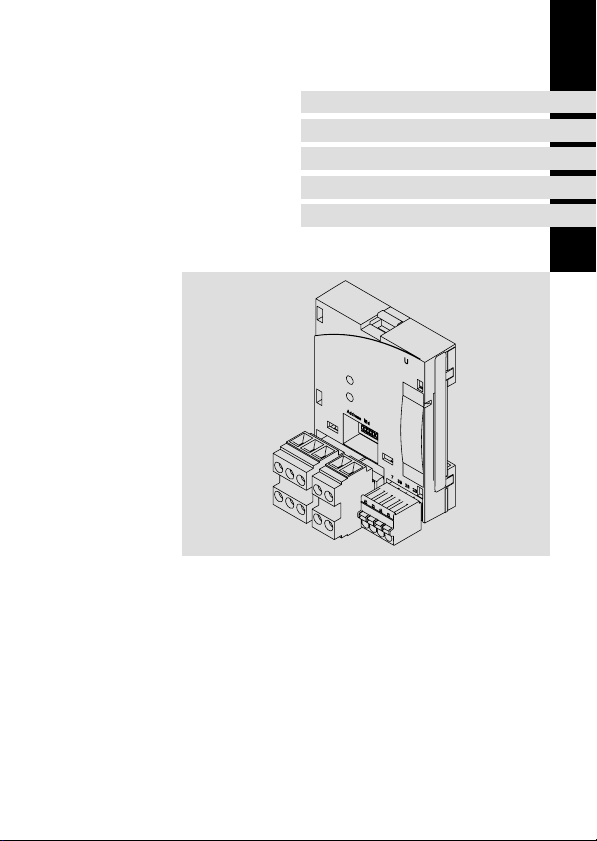
E82ZAFUC010
Funktionsmodul
Function module
Module de fonction
Page 2

Lesen Sie zuerst diese Anleitung und die Dokumentation zum Grundgerät,
bevor Sie mit den Arbeiten beginnen!
Beachten Sie die enthaltenen Sicherheitshinweise.
Please read these instructions and the documentation of the standard
device before you start working!
Observe the safety instructions given therein!
Lire le présent fascicule et la documentation relative à l’appareil de base
avant toute manipulation de l’équipement !
Respecter les consignes de sécurité fournies.
Page 3
E82ZAFUC001C
Page 4

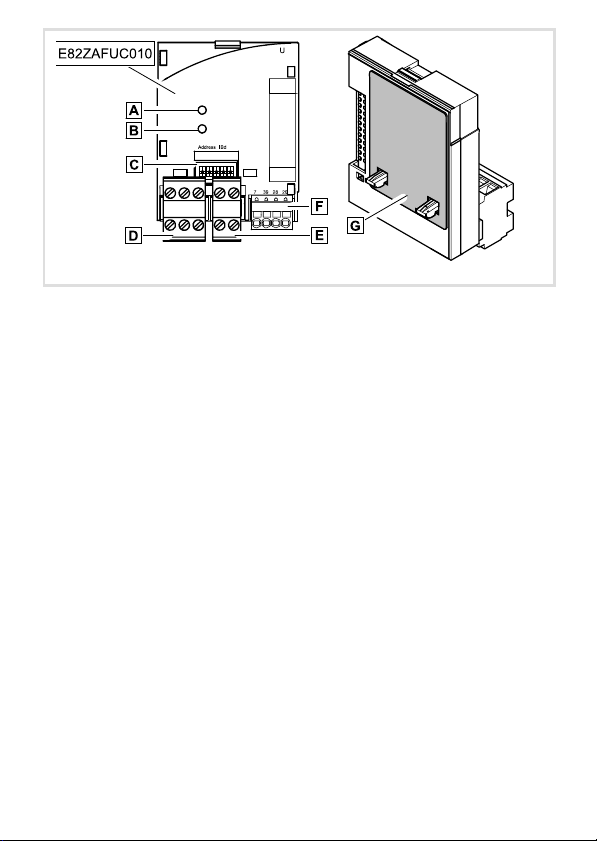
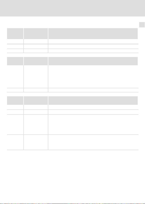
Legende zur Abbildung auf der Ausklappseite
Pos. Beschreibung Ausführliche
Verbindungsstatus zum Grundgerät (zweifarbige LED, grün/rot)
Verbindungsstatus zum Bus (zweifarbige LED, grün/rot)
DIP−Schalter zur Konfiguration
l Knotenadresse ("Address")
l Übertragungsrate ("Bd")
Steckerleiste X3.1, Anschluss für CANopen
Steckerleiste X3.2, Anschluss für externe Spannungsversorgung
Steckerleiste X3.3, Anschluss für
l Reglersperre (CINH)
l interne Versorgung
Typenschild 13
0Abb. 0Tab. 0
Information
38
34
16
4
EDK82ZAFUC010 DE/EN/FR 4.0
Page 5

Inhalt i
1 Über diese Dokumentation 6 . . . . . . . . . . . . . . . . . . . . . . . . . . . . . . . . . . . . . . . . . . . .
Verwendete Konventionen 7 . . . . . . . . . . . . . . . . . . . . . . . . . . . . . . . . . . . . . . . . . . . .
Verwendete Hinweise 8 . . . . . . . . . . . . . . . . . . . . . . . . . . . . . . . . . . . . . . . . . . . . . . . .
2 Sicherheitshinweise 10 . . . . . . . . . . . . . . . . . . . . . . . . . . . . . . . . . . . . . . . . . . . . . . . . . .
3 Produktbeschreibung 11 . . . . . . . . . . . . . . . . . . . . . . . . . . . . . . . . . . . . . . . . . . . . . . . .
Funktion 11 . . . . . . . . . . . . . . . . . . . . . . . . . . . . . . . . . . . . . . . . . . . . . . . . . . . . . . . . . . .
Bestimmungsgemäße Verwendung 11 . . . . . . . . . . . . . . . . . . . . . . . . . . . . . . . . . . . .
Lieferumfang 12 . . . . . . . . . . . . . . . . . . . . . . . . . . . . . . . . . . . . . . . . . . . . . . . . . . . . . . .
Identifikation 13 . . . . . . . . . . . . . . . . . . . . . . . . . . . . . . . . . . . . . . . . . . . . . . . . . . . . . . .
4 Technische Daten 14 . . . . . . . . . . . . . . . . . . . . . . . . . . . . . . . . . . . . . . . . . . . . . . . . . . . .
Allgemeine Daten 14 . . . . . . . . . . . . . . . . . . . . . . . . . . . . . . . . . . . . . . . . . . . . . . . . . . .
Einsatzbedingungen 14 . . . . . . . . . . . . . . . . . . . . . . . . . . . . . . . . . . . . . . . . . . . . . . . . .
Schutzisolierung 15 . . . . . . . . . . . . . . . . . . . . . . . . . . . . . . . . . . . . . . . . . . . . . . . . . . . . .
Daten der Anschlussklemmen 16 . . . . . . . . . . . . . . . . . . . . . . . . . . . . . . . . . . . . . . . . .
Abmessungen 17 . . . . . . . . . . . . . . . . . . . . . . . . . . . . . . . . . . . . . . . . . . . . . . . . . . . . . . .
5 Mechanische Installation 18 . . . . . . . . . . . . . . . . . . . . . . . . . . . . . . . . . . . . . . . . . . . . .
6 Elektrische Installation 19 . . . . . . . . . . . . . . . . . . . . . . . . . . . . . . . . . . . . . . . . . . . . . . .
Umgang mit Steckerleisten 19 . . . . . . . . . . . . . . . . . . . . . . . . . . . . . . . . . . . . . . . . . . . .
EMV−gerechte Verdrahtung 20 . . . . . . . . . . . . . . . . . . . . . . . . . . . . . . . . . . . . . . . . . . .
Verdrahtung mit einem Leitrechner 21 . . . . . . . . . . . . . . . . . . . . . . . . . . . . . . . . . . . .
Busleitungslänge 22 . . . . . . . . . . . . . . . . . . . . . . . . . . . . . . . . . . . . . . . . . . . . . . . . . . . .
Spannungsversorgung 25 . . . . . . . . . . . . . . . . . . . . . . . . . . . . . . . . . . . . . . . . . . . . . . .
Belegung der Anschlussklemmen 27 . . . . . . . . . . . . . . . . . . . . . . . . . . . . . . . . . . . . . .
Leitungsquerschnitte und Schraubenanzugsmomente 28 . . . . . . . . . . . . . . . . . . . . .
7 Inbetriebnahme 29 . . . . . . . . . . . . . . . . . . . . . . . . . . . . . . . . . . . . . . . . . . . . . . . . . . . . .
Vor dem ersten Einschalten 29 . . . . . . . . . . . . . . . . . . . . . . . . . . . . . . . . . . . . . . . . . . .
Inbetriebnahmeschritte 30 . . . . . . . . . . . . . . . . . . . . . . . . . . . . . . . . . . . . . . . . . . . . . .
Leitsystem (Master) konfigurieren 33 . . . . . . . . . . . . . . . . . . . . . . . . . . . . . . . . . . . . .
Knotenadresse und Übertragungsrate einstellen 34 . . . . . . . . . . . . . . . . . . . . . . . . .
Netzspannung zuschalten 37 . . . . . . . . . . . . . . . . . . . . . . . . . . . . . . . . . . . . . . . . . . . .
8 Diagnose 38 . . . . . . . . . . . . . . . . . . . . . . . . . . . . . . . . . . . . . . . . . . . . . . . . . . . . . . . . . . .
LED−Statusanzeigen 38 . . . . . . . . . . . . . . . . . . . . . . . . . . . . . . . . . . . . . . . . . . . . . . . . .
EDK82ZAFUC010 DE/EN/FR 4.0
5
Page 6

1 Über diese Dokumentation
1 Über diese Dokumentation
Inhalt
Diese Dokumentation enthält ...
ƒ Sicherheitshinweise, die Sie unbedingt beachten müssen;
ƒ Angaben über Versionsstände der zu verwendenden Lenze Grundgeräte;
ƒ Informationen zur mechanischen und elektrischen Installation des Funktionsmoduls;
ƒ Informationen zur Inbetriebnahme des Funktionsmoduls;
ƒ Technische Daten.
Informationen zur Gültigkeit
Die Informationen in dieser Dokumentation sind gültig für folgende Geräte:
Funktionsmodul Typenbezeichnung ab Hardwarestand ab Softwarestand
CANopen PT E82ZAFUC010 1x 1x
Zielgruppe
Diese Dokumentation wendet sich an Personen, die das beschriebene Produkt nach Projektvorgabe installieren und in Betrieb nehmen.
Tipp!
Informationen und Hilfsmittel rund um die Lenze−Produkte finden Sie im
Download−Bereich unter
http://www.Lenze.com
6
EDK82ZAFUC010 DE/EN/FR 4.0
Page 7

Über diese Dokumentation
Verwendete Konventionen
Verwendete Konventionen
Diese Dokumentation verwendet folgende Konventionen zur Unterscheidung verschiedener Arten von Information:
Informationsart Auszeichnung Beispiele/Hinweise
Zahlenschreibweise
Dezimaltrennzeichen
Symbole
Seitenverweis
Punkt Es wird generell der Dezimalpunkt
verwendet.
Beispiel: 1234.56
Verweis auf eine andere Seite mit zusätzlichen Informationen
Beispiel: 16 = siehe Seite 16
1
EDK82ZAFUC010 DE/EN/FR 4.0
7
Page 8

1 Über diese Dokumentation
Verwendete Hinweise
Verwendete Hinweise
Um auf Gefahren und wichtige Informationen hinzuweisen, werden in dieser Dokumentation folgende Piktogramme und Signalwörter verwendet:
Sicherheitshinweise
Aufbau der Sicherheitshinweise:
Gefahr!
(kennzeichnet die Art und die Schwere der Gefahr)
Hinweistext
(beschreibt die Gefahr und gibt Hinweise, wie sie vermieden werden kann)
Piktogramm und Signalwort Bedeutung
Gefahr von Personenschäden durch gefährliche elektrische Spannung
Gefahr!
Gefahr!
Stop!
Hinweis auf eine unmittelbar drohende Gefahr, die den
Tod oder schwere Verletzungen zur Folge haben kann,
wenn nicht die entsprechenden Maßnahmen getroffen
werden.
Gefahr von Personenschäden durch eine allgemeine Gefahrenquelle
Hinweis auf eine unmittelbar drohende Gefahr, die den
Tod oder schwere Verletzungen zur Folge haben kann,
wenn nicht die entsprechenden Maßnahmen getroffen
werden.
Gefahr von Sachschäden
Hinweis auf eine mögliche Gefahr, die Sachschäden zur
Folge haben kann, wenn nicht die entsprechenden Maßnahmen getroffen werden.
8
EDK82ZAFUC010 DE/EN/FR 4.0
Page 9

Anwendungshinweise
Piktogramm und Signalwort Bedeutung
Über diese Dokumentation
Verwendete Hinweise
1
Hinweis!
Tipp!
Wichtiger Hinweis für die störungsfreie Funktion
Nützlicher Tipp für die einfache Handhabung
Verweis auf andere Dokumentation
EDK82ZAFUC010 DE/EN/FR 4.0
9
Page 10

2 Sicherheitshinweise
2 Sicherheitshinweise
Gefahr!
Unsachgemäßer Umgang mit dem Funktionsmodul und dem Grundgerät kann
schwere Personenschäden und Sachschäden verursachen.
Beachten Sie die in der Dokumentation zum Grundgerät enthaltenen
Sicherheitshinweise und Restgefahren.
Stop!
Elektrostatische Entladung
Durch elektrostatische Entladung können elektronische Bauteile innerhalb des
Funkionsmoduls beschädigt oder zerstört werden.
Mögliche Folgen:
ƒ Das Funktionsmodul ist defekt.
ƒ Die Feldbus−Kommunikation ist nicht möglich oder fehlerhaft.
Schutzmaßnahmen
ƒ Befreien Sie sich vor dem Berühren des Moduls von elektrostatischen
Aufladungen.
10
EDK82ZAFUC010 DE/EN/FR 4.0
Page 11

Produktbeschreibung
Funktion
3 Produktbeschreibung
Funktion
Das Funktionsmodul koppelt Lenze Frequenzumrichter an das Kommunikationssystem
CANopen.
Bestimmungsgemäße Verwendung
Das Funktionsmodul ...
ƒ ist eine Zubehör−Baugruppe, die mit folgenden Lenze Grundgeräten eingesetzt
werden kann:
Produktreihe Gerätebezeichnung ab Hardwarestand
Frequenzumrichter 8200 vector Vx14
ƒ ist ein Betriebsmittel zum Einsatz in industriellen Starkstromanlagen.
Jede andere Verwendung gilt als sachwidrig!
Tipp!
Weiterführende Informationen zu diesem Funktionsmodul finden Sie im
entsprechenden Kommunikationshandbuch.
Die PDF−Datei finden Sie im Download−Bereich unter:
http://www.Lenze.com
3
EDK82ZAFUC010 DE/EN/FR 4.0
11
Page 12
3 Produktbeschreibung
Lieferumfang
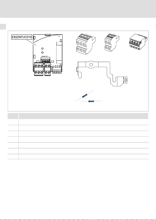
Lieferumfang
Pos. Lieferumfang
Funktionsmodul E82ZAFUC010
Montageanleitung
Steckerleiste mit Doppel−Schraubanschluss, 3−polig
Steckerleiste mit Doppel−Schraubanschluss, 2−polig
Steckerleiste mit Federkraftanschluss, 4−polig
Befestigungsbügel
Zwei Busabschluss−Widerstände (je 120 W)
E82ZAFU001C, E82ZAFX007, 016−019
12
EDK82ZAFUC010 DE/EN/FR 4.0
Page 13
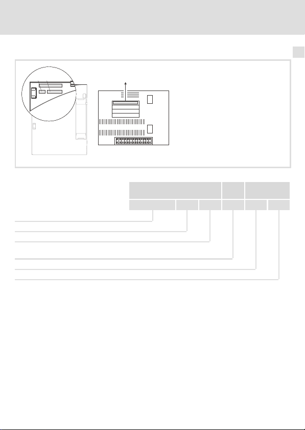
Identifikation
APPLICATION
010 / 3A22
Produktbeschreibung
Identifikation
3
APPLICATION
010/ 3A22
Produktreihe
CANopen
Gerätegeneration
Variante: PT (Plug Terminal) mit Federkraft− und Schraubanschluss
Hardwarestand
Softwarestand
L
Type
Id.-No.
Prod.-No.
Ser.-No.
E82AF000P0B201XX
E82ZAFX005
E82ZAF U C 010 1x 1x
EDK82ZAFUC010 DE/EN/FR 4.0
13
Page 14
4 Technische Daten
Allgemeine Daten
4 Technische Daten
Allgemeine Daten
Bereich Werte
Bestell−Bezeichnung E82ZAFUC010
Kommunikationsprofil CANopen, DS301 V4.02
Kommunikationsmedium DIN ISO 11898
Netzwerk−Topologie
Einstellbare Knotenadresse Maximal 127 (mit Repeater)
Mögliche Teilnehmer je
Segment
CANopen−Teilnehmer Slave
Übertragungsrate [kBit/s] 10, 20, 50, 125, 250, 500, 1000
Prozessdaten−Wörter 1 ... 12 Wörter
Einsatzbedingungen
Umgebungsbedingungen
Klimatisch
Lagerung
Transport IEC/EN 60721−3−2 2K3 (−25 ... +70 °C)
Betrieb Entsprechend der Daten des verwendeten Lenze Grundgerätes (siehe
Verschmutzung EN 61800−5−1 Verschmutzungsgrad 2
Schutzart IP20 (Berührschutz nach NEMA 250 Typ 1)
Beidseitig abgeschlossene Linie mit 120 W Widerstand
l Bei Teilnehmern E82ZAFUC010: 106 (max.)
l Bei unterschiedlichen Teilnehmern:
Siehe Hinweise zum Mischbetrieb 23
IEC/EN 60721−3−1 1K3 (−25 ... +60 °C)
Dokumentation des Grundgerätes).
14
EDK82ZAFUC010 DE/EN/FR 4.0
Page 15

Technische Daten
Schutzisolierung
Schutzisolierung
Isolierung zwischen Bus und ... Art der Isolierung (nach EN 61800−5−1)
l Leistungsteil 8200 vector
l Bezugserde / PE (X3.2/7, X3.3/7)
l externer Versorgung (X3.2/59)
l Versorgung für CINH (X3.3/20)
l Reglersperre, CINH (X3.3/28)
Verstärkte Isolierung
Betriebsisolierung
Betriebsisolierung
Betriebsisolierung
Betriebsisolierung
4
EDK82ZAFUC010 DE/EN/FR 4.0
15
Page 16
4 Technische Daten
Daten der Anschlussklemmen
Daten der Anschlussklemmen
Klemme
X3.1/
CG CAN−GND Bezugspotenzial für CAN
CL CAN−LOW CAN−Datenleitung (LOW)
CH CAN−HIGH CAN−Datenleitung (HIGH)
Bezeichnung Funktion /Pegel
Klemme
X3.2/
59 Externe DC−Spannungsversorgung des Funktionsmoduls
7 GND1 Bezugspotenzial für X3.3/20
Klemme
X3.3/
7 GND1 Bezugspotenzial für X3.3/20
39 GND2 Bezugspotenzial 2 der Reglersperre (CINH) an X3.3/28
28 CINH Reglersperre
20 DC−Spannungsquelle zur externen Versorgung der Reglersperre
16
Bezeichnung Funktion / Pegel
Bezeichnung Funktion / Pegel
l +24VDC±10% (Bezug: GND1)
l Stromaufnahme an 24 V DC: 80 mA
Beim Durchschleifen der Versorgungsspannung zu anderen
Busteilnehmern über die Klemme 59 darf der fließende Strom max.
3A betragen.
l Eingangswiderstand: 3.3 kW
l Start = HIGH (+12 ... +30 V)
l Stop = LOW (0 ... +3 V)
(Bezug: GND2)
(CINH)
l +20 V (Bezug: GND1)
l I
= 10 mA
max
EDK82ZAFUC010 DE/EN/FR 4.0
Page 17
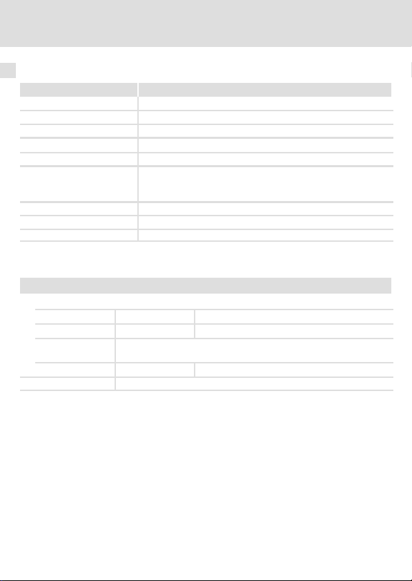
Abmessungen
alle Maße in mm
Technische Daten
Abmessungen
E82ZAFU001A
4
EDK82ZAFUC010 DE/EN/FR 4.0
17
Page 18

5 Mechanische Installation
5 Mechanische Installation
Folgen Sie zur mechanischen Installation des Funktionsmoduls den Hinweisen in der Montageanleitung des Grundgerätes.
Die Montageanleitung des Grundgerätes ...
ƒ ist Teil des Lieferumfangs und liegt jedem Gerät bei.
ƒ gibt Hinweise, um Beschädigungen durch unsachgemäße Behandlung zu vermeiden.
ƒ beschreibt die einzuhaltende Reihenfolge der Installationsschritte.
18
EDK82ZAFUC010 DE/EN/FR 4.0
Page 19
Elektrische Installation
Umgang mit Steckerleisten
6 Elektrische Installation
Umgang mit Steckerleisten
Stop!
Um Steckerleisten und Kontakte nicht zu beschädigen:
ƒ Steckerleisten nur aufstecken / abziehen wenn der Antriebsregler vom
Netz getrennt ist.
ƒ Steckerleisten erst verdrahten, dann aufstecken.
ƒ Nicht belegte Steckerleisten ebenfalls aufstecken.
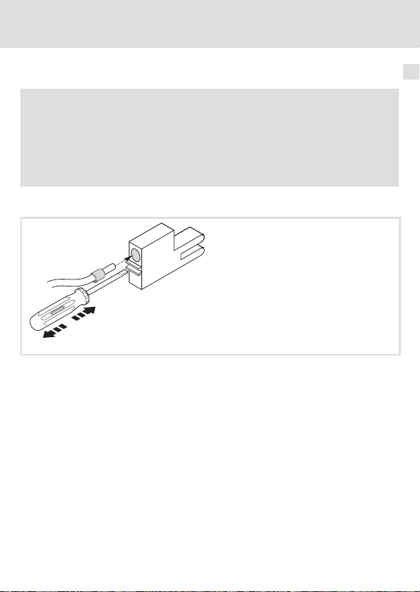
Gebrauch der Steckerleiste mit Federkraftanschluss
6
E82ZAFX013
EDK82ZAFUC010 DE/EN/FR 4.0
19
Page 20

6 Elektrische Installation
EMV−gerechte Verdrahtung
EMV−gerechte Verdrahtung
Für eine EMV−gerechte Verdrahtung beachten Sie folgende Punkte:
Hinweis!
ƒ Steuer−/Datenleitungen getrennt von Motorleitungen verlegen.
ƒ Legen Sie die Schirme der Steuer−/Datenleitungen bei digitalen Signalen
beidseitig auf.
ƒ Zur Vermeidung von Potenzialdifferenzen zwischen den
Kommunikationsteilnehmern eine Ausgleichsleitung mit einem
Querschnitt von mindestens 16mm
ƒ Beachten Sie die weiteren Hinweise zur EMV−gerechten Verdrahtung in der
Dokumentation des Grundgerätes.
Vorgehensweise bei der Verdrahtung
1. Bustopologie einhalten, deshalb keine Stichleitungen verwenden.
2. Hinweise und Verdrahtungsvorschriften in den Unterlagen zum Steuerungssystem
beachten.
3. Nur Kabel verwenden, die den aufgeführten Spezifikationen entsprechen (21).
4. Zulässige Busleitungslänge einhalten (22)
5. Busabschlusswiderstände von je 120 W (Lieferumfang) anschließen:
– nur am physikalisch ersten und letzten Busteilnehmer
– zwischen den Klemmen CAN−LOW und CAN−HIGH
2
einsetzen (Bezug:PE).
.
20
EDK82ZAFUC010 DE/EN/FR 4.0
Page 21
Elektrische Installation
Verdrahtung mit einem Leitrechner
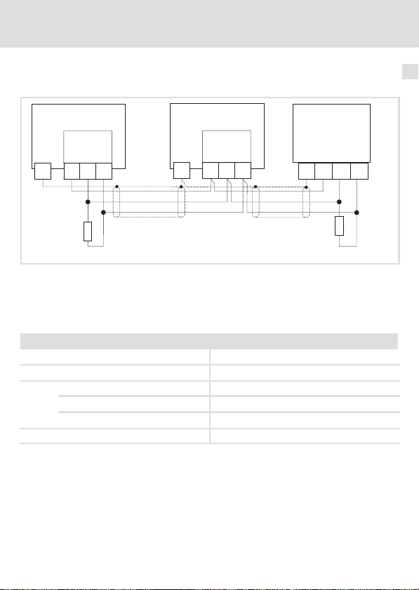
Verdrahtung mit einem Leitrechner
In folgender Abbildung ist die CAN−Leitungsführung am Funktionsmodul dargestellt:
8200 vector
8200 vector
SPS/PC
6
E82ZAFUC010
CG CG
CL CL
+
Frequenzumrichter der Reihe 8200 vector/8200 motec mit aufgesteckten Funktionsmodulen und der CANopen−Master kommunizieren über CANopen.
Spezifikation des Übertragungskabels
Wir empfehlen CAN−Kabel nach ISO 11898−2 zu verwenden:
CAN−Kabel nach ISO 11898−2
Kabeltyp Paarverseilt mit Abschirmung
Impedanz
Leitungswiderstand/−querschnitt
Signallaufzeit
CH CH
120
Kabellänge £ 300 m £ 70 mW/m / 0.25 0.34 mm2 (AWG22)
Kabellänge 301 1000 m
E82ZAFUC010
+
120 W (95 ... 140 W)
£ 40 mW/m / 0.5 mm
£ 5 ns/m
+
2
(AWG20)
GND
120
LOW
HIGH
E82ZAFU015
EDK82ZAFUC010 DE/EN/FR 4.0
21
Page 22
6 Elektrische Installation
Busleitungslänge
Busleitungslänge
Hinweis!
Halten Sie die zulässigen Leitungslängen unbedingt ein!
1. Überprüfen Sie die Einhaltung der Gesamt−Leitungslänge in Tab. 1.
Durch die Übertragungsrate ist die Gesamt−Leitungslänge festgelegt.
Übertragungsrate [kBit/s] Gesamt−Leitungslänge [m]
10 8000
20 3900
50 1500
125 630
250 290
500 120
1000 25
Tab. 1 Gesamt−Leitungslänge
2. Überprüfen Sie die Einhaltung der Segment−Leitungslänge in Tab. 2.
Die Segment−Leitungslänge wird durch den verwendeten Leitungsquerschnitt und die Anzahl Teilnehmer je Segement festgelegt. Ohne Repeater ist die Segment−Leitungslänge
gleich der Gesamt−Leitungslänge.
Maximale Anzahl
Teilnehmer je Segment
2 240 m 430 m 650 m 940 m
5 230 m 420 m 640 m 920 m
10 230 m 410 m 620 m 900 m
20 210 m 390 m 580 m 850 m
32 200 m 360 m 550 m 800 m
63 170 m 310 m 470 m 690 m
100 150 m 270 m 410 m 600 m
Tab. 2 Segment−Leitungslänge
Leitungsquerschnitt
2
0.25 mm
0.5 mm
2
0.75 mm
2
1.0 mm
2
22
EDK82ZAFUC010 DE/EN/FR 4.0
Page 23

Elektrische Installation
Busleitungslänge
3. Vergleichen Sie die beiden ermittelten Werte miteinander.
Wenn der aus Tab. 2 ermittelte Wert kleiner als die zu realiserende Gesamt−Leitungslänge
aus Tab. 1 sein sollte, müssen Repeater eingesetzt werden. Repeater unterteilen die Gesamt−Leitungslänge in Segmente.
Hinweis!
ƒ Beachten Sie die Reduzierung der Gesamt−Leitungslänge aufgrund der
Signalverzögerung des Repeaters (siehe Beispiel 24).
ƒ Mischbetrieb
– Mischbetrieb liegt vor, wenn verschiedene Teilnehmer an einem Netz
betrieben werden.
– Wenn bei gleicher Übertragungsrate die zugehörigen
Gesamt−Leitungslängen der Teilnehmer unterschiedlich sind, muss zur
Bestimmung der max. Leitungslänge der kleinere Wert verwendet
werden.
Beispiel: Auswahlhilfe
Vorgaben
l Leitungsquerschnitt:
l Teilnehmeranzahl:
l Repeater:
Halten Sie unter Berücksichtigung der Vorgaben folgende Leitungslängen / Anzahl Repeater ein:
Übertragungsrate [kBit/s] 10 20 50 125 250 500 1000
Max. Leitungslänge [m] 8000 3900 1500 630 290 120 25
Segment−Leitungslänge [m] 270 270 270 270 290 120 25
Anzahl der Repeater 33 16 6 2 − − −
2
(gemäß Kabel−Spezifikation 21)
0.5 mm
100
Lenze−Repeater, Typ 2176 (Leitungsreduzierung: 30 m)
6
EDK82ZAFUC010 DE/EN/FR 4.0
23
Page 24

6 Elektrische Installation
Busleitungslänge
Repeater−Einsatz prüfen
Vorgaben
l Übertragungsrate:
l Leitungsquerschnitt:
l Teilnehmeranzahl:
l Leitungslänge:
Prüfschritte Leitungslänge siehe
1. Gesamt−Leitungslänge bei 125 kBit/s: 630 m Tab. 1
2. Segment−Leitungslänge für 28 Teilnehmer und einem Leitungsquerschnitt von 0.5 mm
3. Vergleich: Der Wert in Pkt. 2 ist kleiner als die zu realisierende Leitungslänge von 1500 m.
Folgerung
l Ohne Repeater−Einsatz ist die zu realisierende Leitungslänge von 1500 m nicht möglich.
l Es muss ein Repeater nach 360 m (Pkt. 2.) eingesetzt werden.
Ergebnis
l Verwendet wird der Lenze−Repeater, Typ 2176 (Leitungsreduzierung: 30 m)
l Berechnung der max. Leitungslänge für das
– erste Segment: 360 m
– zweite und jedes weitere Segment: 360 m (entsprechend Tab. 1) minus 30 m (Leitungsreduzie-
rung bei Einsatz eines Repeaters)
à Max. erreichbare Leitungslänge mit vier Repeatern: 1680 m.
à Damit ist die vorgegebene Leitungslänge realisierbar.
125 kBit/s
0.5 mm
28
1500 m
2
:
2
360 m Tab. 2
Hinweis!
Die Verwendung eines weiteren Repeaters wird empfohlen als
ƒ Service−Schnittstelle
Vorteil: Störungsfreies Ankoppeln im laufenden Bus−Betrieb möglich.
ƒ Einmess−Schnittstelle
Vorteil: Einmess−/Programmiergerät bleibt galvanisch getrennt.
24
EDK82ZAFUC010 DE/EN/FR 4.0
Page 25
Elektrische Installation
Spannungsversorgung
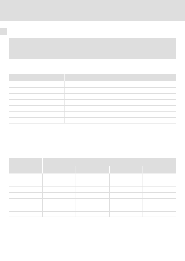
Spannungsversorgung
Versorgung der Reglersperre (CINH) über die interne Spannungsquelle (X3.3/20)
6
GND1
CH 7
CL
CG
X3.1 X3.2 X3.3
CAN-GND
CAN-LOW
CAN-HIGH
Versorgung der Reglersperre (CINH) über die externe Spannungsquelle
CH 7
CL
CG
X3.1 X3.2 X3.3
CAN-GND
CAN-LOW
CAN-HIGH
59
GND1
59
GND2
GND2
_
+
20 V
28397
20
E82ZAFU011
20 V
28397
20
E82ZAFU012
EDK82ZAFUC010 DE/EN/FR 4.0
25
Page 26
6 Elektrische Installation
Spannungsversorgung
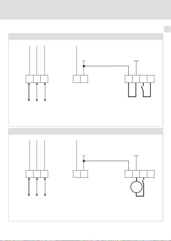
Versorgung des Funktionmoduls und der Reglersperre (CINH) über die externe Spannungsquelle
GND1
CH 7
CL
CG
X3.1 X3.2 X3.3
59
_
+
CAN-GND
CAN-LOW
CAN-HIGH
Für den Betrieb notwendige Mindestverdrahtung
GND2
_
+
20 V
28397
20
E82ZAFU013
26
EDK82ZAFUC010 DE/EN/FR 4.0
Page 27
Belegung der Anschlussklemmen
Belegung der Anschlussklemmen
Klemme
X3.1/
CG CAN−GND Bezugspotenzial für CAN
CL CAN−LOW CAN−Datenleitung (LOW)
CH CAN−HIGH CAN−Datenleitung (HIGH)
Bezeichnung Funktion /Pegel
Elektrische Installation
6
Klemme
X3.2/
59 Externe DC−Spannungsversorgung des Funktionsmoduls
7 GND1 Bezugspotenzial für X3.3/20
Klemme
X3.3/
7 GND1 Bezugspotenzial für X3.3/20
39 GND2 Bezugspotenzial 2 der Reglersperre (CINH) an X3.3/28
28 CINH Reglersperre
20 DC−Spannungsquelle zur externen Versorgung der Reglersperre
EDK82ZAFUC010 DE/EN/FR 4.0
Bezeichnung Funktion / Pegel
l +24VDC±10% (Bezug: GND1)
l Stromaufnahme an 24 V DC: 80 mA
Beim Durchschleifen der Versorgungsspannung zu anderen
Busteilnehmern über die Klemme 59 darf der fließende Strom max.
3A betragen.
Bezeichnung Funktion / Pegel
l Eingangswiderstand: 3.3 kW
l Start = HIGH (+12 ... +30 V)
l Stop = LOW (0 ... +3 V)
(Bezug: GND2)
(CINH)
l +20 V (Bezug: GND1)
l I
= 10 mA
max
27
Page 28
6 Elektrische Installation
Leitungsquerschnitte und Schraubenanzugsmomente
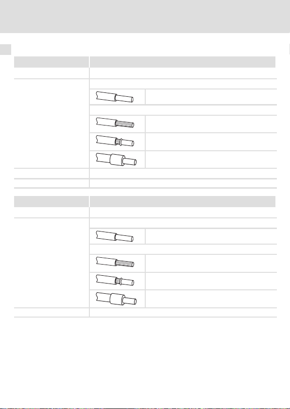
Leitungsquerschnitte und Schraubenanzugsmomente
Bereich Werte
Elektrischer Anschluss Steckerleiste mit Doppel−Schraubanschluss
Anschlussmöglichkeiten
Anzugsmoment 0.5 ... 0.6 Nm (4.4 ... 5.3 lb−in)
Abisolierlänge 10 mm
starr:
flexibel:
2
1.5 mm
(AWG 16)
ohne Aderendhülse
2
(AWG 16)
1.5 mm
mit Aderendhülse, ohne Kunststoffhülse
2
(AWG 16)
1.5 mm
mit Aderendhülse, mit Kunststoffhülse
2
(AWG 16)
1.5 mm
Bereich Werte
Elektrischer Anschluss 2−polige Steckerleiste mit Federkraftanschluss
Anschlussmöglichkeiten
Abisolierlänge 9 mm
starr:
flexibel:
2
1.5 mm
(AWG 16)
ohne Aderendhülse
2
(AWG 16)
1.5 mm
mit Aderendhülse, ohne Kunststoffhülse
2
(AWG 16)
1.5 mm
mit Aderendhülse, mit Kunststoffhülse
2
(AWG 16)
1.5 mm
28
EDK82ZAFUC010 DE/EN/FR 4.0
Page 29

Inbetriebnahme
Vor dem ersten Einschalten
7 Inbetriebnahme
Vor dem ersten Einschalten
Stop!
Bevor Sie das Grundgerät mit dem Funktionsmodul erstmalig einschalten,
überprüfen Sie ...
ƒ die gesamte Verdrahtung auf Vollständigkeit, Kurzschluss und Erdschluss.
ƒ ob das Bussystem beim physikalisch ersten und letzten Busteilnehmer
durch einen Busabschluss−Widerstand abgeschlossen ist.
Hinweis!
Eine allgemeingültige Beschreibung der Inbetriebnahme von
Funktionsmodulen mit CANopen−Kommunikationsprofil, über eines der dazu
zahlreich am Markt erhältlichen Programme, ist Rahmen dieser
Dokumentation nicht möglich.
Ein solches Programm ist nicht Teil des Lenze Lieferumfangs.
7
EDK82ZAFUC010 DE/EN/FR 4.0
29
Page 30

7 Inbetriebnahme
Inbetriebnahmeschritte
Inbetriebnahmeschritte
Hinweis!
Halten Sie unbedingt die Einstellreihenfolge ein.
Schritt Beschreibung Ausführliche
1. Leitsystem (CANopen−Master) für die Kommunikation mit dem Funk-
2. Grundgerät über Klemme 28 (CINH) sperren.
3. Netzspannung zuschalten und, wenn vorhanden, separate Span-
4. Statusanzeige überprüfen.
tionsmodul konfigurieren.
l Klemme 28 auf LOW−Pegel legen.
l Das Grundgerät kann später über den Bus gesperrt und freigege-
ben werden.
nungsversorgung des Funktionsmoduls zuschalten.
l Das Grundgerät ist nach ca. 1 Sekunde betriebsbereit.
l Die Reglersperre (CINH) ist aktiv.
Reaktion
l Die zweifarbige LED "Verbindungsstatus zum Grundgerät" ()
leuchtet konstant grün.
l Die LED "Status der CANopen−Kommunikation" () blinkt.
Voraussetzung: Es müssen bereits andere Teilnehmer am Bus
angeschlossen sein.
l Keypad: (falls aufgesteckt)
Information
33
Dokumentation
des Grundgerätes
37
38
30
EDK82ZAFUC010 DE/EN/FR 4.0
Page 31

Inbetriebnahme
Inbetriebnahmeschritte
7
BeschreibungSchritt
5. A Knotenadresse einstellen über ...
6.
7. Funktionsmodul als Quelle für Steuerbefehle und Sollwerte wählen.
8. Gegebenenfalls Prozess−Ausgangsworte des Masters über C1511 den
9. Gegebenenfalls Prozess−Ausgangsworte des Grundgerätes über
10. Prozess−Ausgangsdaten des Masters mit C1512 = 65535 freigeben.
– C1509 oder
– DIP−Schalter S1 ... S7.
B Übertragungsrate einstellen über ...
– C1516 oder
– DIP−Schalter S8 ... S10.
Gelten die Einstellungen über Codestelle (DIP−Schalter S1 ... S7 = OFF),
so muss nach einem Parametersatz−Transfer die Knotenadresse und
Übertragungsrate neu zugewiesen werden.
C Schalten Sie die Spannungsversorgung des Funktionsmoduls und
des Grundgerätes aus− und wieder ein, um geänderte Einstellungen zu übernehmen.
Die Änderungen von der Knotenadresse und Übertragungsrate über
Keypad werden sofort wirksam.
Sie können jetzt mit dem Grundgerät kommunizieren, d. h. alle Codestellen lesen und alle beschreibbaren Codestellen an Ihre Anwendung
anpassen.
Reaktion
Die LED "Status der CANopen−Kommunikation" (
Bus aktiv ist.
l C0005 = 200 einstellen.
– Eine Vorkonfiguration für den Betrieb mit dem Funktions-
modul wird durchgeführt.
– Steuerworte und Statusworte sind dabei bereits verknüpft.
Prozess−Eingangsworten des Grundgerätes zuweisen.
C1510 den Prozess−Eingangsdaten des Masters zuweisen.
Nur notwendig wenn C1511 verändert wurde.
) blinkt, wenn der
Ausführliche
Information
34
Dokumentation
des Grundgerätes
38
EDK82ZAFUC010 DE/EN/FR 4.0
31
Page 32

7 Inbetriebnahme
Inbetriebnahmeschritte
BeschreibungSchritt
11.
12. Grundgerät über Klemme 28 (CINH) freigeben.
13. Sollwert vorgeben.
14. Der Antrieb läuft jetzt an.
15. Grundgerät sperren.
Das Leitsystem bewirkt den Wechsel in den Zustand "Operational"
beim Funktionsmodul.
Reaktion
l Zweifarbige LED "Verbindungsstatus zum Grundgerät" () leuch-
tet konstant grün.
l Sie können über die PDOs (z. B. Statuswort) lesen oder Sollwerte
(z. B. Frequenzsollwert) schreiben.
l Klemme 28 auf HIGH−Pegel legen.
l Der Master sendet den Sollwert über das gewählte Prozess−Aus-
gangswort.
l über den Bus (z. B. Steuerwort Bit 9) oder
l Klemme 28 (CINH) auf LOW−Pegel legen
Ausführliche
Information
38
32
EDK82ZAFUC010 DE/EN/FR 4.0
Page 33

Leitsystem (Master) konfigurieren
Inbetriebnahme
Leitsystem (Master) konfigurieren
Zur Kommunikation mit dem Funktionsmodul muss zunächst das Leitsystem konfiguriert
werden.
Einstellungen am CANopen−Master
Zur Projektierung des CAN−Busses muss in der Projektierungssoftware des CANopen−
Masters die Gerätebeschreibungsdatei (EDS−Datei) der Kommunikationsbaugruppe eingelesen werden.
Die EDS−Datei kann im Download−Bereich unter http://www.Lenze.com heruntergeladen
werden.
7
EDK82ZAFUC010 DE/EN/FR 4.0
33
Page 34

7 Inbetriebnahme
Knotenadresse und Übertragungsrate einstellen
Knotenadresse und Übertragungsrate einstellen
Hinweis!
Die Knotenadresse und die Übertragungsrate können Sie über DIP−Schalter
oder Codestellen einstellen.
ƒ Für jeden Teilnehmer muss eine eindeutige Knotenadresse von 1 ... 63
eingestellt werden.
ƒ Die Übertragungsrate muss bei allen Antriebsreglern und dem Leitrechner
(Master) identisch eingestellt werden.
ƒ Wenn sich die DIP−Schalter S1 ... S7 in Stellung OFF befinden, sind die
Codestellen−Einstellungen für die Knotenadresse/Übertragungsrate aktiv.
Wird ein DIP−Schalter in Stellung ON gesetzt, wird die Knotenadresse
(C1509)/Übertragungsrate (C1516) mit den entsprechenden Werten der
Schalterstellungen überschrieben.
Einstellungen über Codestellen
ƒ DIP−Schalter S1 ... S7 = OFF (Lenze−Einstellung)
ƒ Die Knotenadresse über C1509 einstellen.
ƒ Die Übertragungsrate über C1516 einstellen.
Einstellungen über frontseitige DIP−Schalter
ƒ Die Knotenadresse über DIP−Schalter S1 ... S7 einstellen.
ƒ Die Übertragungsrate über DIP−Schalter S8 ... S10 einstellen.
Geänderte Einstellungen übernehmen
ƒ Schalten Sie die Spannungsversorgung des Funktionsmoduls und des
Antriebsreglers aus und anschließend wieder ein, um geänderte
Einstellungen zu aktivieren.
34
EDK82ZAFUC010 DE/EN/FR 4.0
Page 35

Knotenadresse einstellen
Knotenadresse und Übertragungsrate einstellen
Inbetriebnahme
7
ON
1627438
Abb. 1 Adressierung über DIP−Schalter
5
910
ON
OFF
Hinweis!
Die Knotenadressen bei mehreren vernetzten Antriebsreglern müssen sich
voneinander unterscheiden.
ƒ Die Knotenadressen bei mehreren vernetzten CAN−Teilnehmern müssen sich
voneinander unterscheiden.
ƒ Alle in Stellung ON befindlichen Schalter (1 ... 7) ergeben in der Summe der
Wertigkeiten die gewünschte Knotenadresse.
Beispiel
Schalter Wertigkeit
164OFF
2 32 OFF
3 16 ON
4 8 OFF
5 4 ON
6 2 ON
7 1 ON
Schaltzustand Knotenadresse
16 + 4 + 2 + 1 = 23
EDK82ZAFUC010 DE/EN/FR 4.0
35
Page 36

7 Inbetriebnahme
Knotenadresse und Übertragungsrate einstellen
Übertragungsrate einstellen
ON
1627438
Abb. 2 Einstellen der Übertragungsrate
5
910
ON
OFF
Hinweis!
Die Übertragungsrate muss bei allen Antriebsreglern und dem Leitrechner
identisch eingestellt werden.
Übertragungsrate [kBit/s] S8 S9 S10
10 ON ON OFF
20 ON OFF ON
50 OFF ON ON
125 OFF ON OFF
250 OFF OFF ON
500 OFF OFF OFF
1000 ON OFF OFF
Automatische Erkennung ON ON ON
Automatische Erkennung der Übertragungsrate
Hinweis!
Die automatische Übertragungsratenerkennung ist nur möglich, wenn schon
andere Teilnehmer über den CAN−Bus fehlerfrei Telegramme senden:
ƒ Nach dem Einschalten oder einem "Reset Node" sucht das Funktionsmodul
die richtige Übertragungsrate, indem es die gesendeten Telegramme der
anderen Teilnehmer auswertet.
ƒ Ist die richtige Übertragungsrate erkannt, wird sie vom Funktionsmodul
übernommen.
36
EDK82ZAFUC010 DE/EN/FR 4.0
Page 37

Inbetriebnahme
Netzspannung zuschalten
Netzspannung zuschalten
Hinweis!
Wenn Sie die externe Spannungsversorgung des Funktionsmoduls benutzen,
schalten Sie diese ebenfalls ein.
ƒ Nach dem Einschalten der Versorgungsspannung ist das Grundgerät nach ca. 1 s
betriebsbereit.
ƒ Die Reglersperre ist aktiv.
ƒ Die grüne LED auf der Frontseite des Funktionsmoduls leuchtet.
Schutz vor unkontrolliertem Wiederanlauf
7
Hinweis!
Aufbau der Kommunikation
Zum Aufbau der Kommunikation ist es beim extern versorgten
Funktionsmodul erforderlich, auch das Grundgerät anfangs einzuschalten.
ƒ Die weitere Kommunikation des extern versorgten Moduls bleibt
anschließend unabhängig vom Einschaltzustand des Grundgerätes.
Schutz vor unkontrolliertem Wiederanlauf
Nach einer Störung (z. B. kurzzeitiger Netzausfall) ist der Wiederanlauf eines
Antriebs in manchen Fällen unerwünscht oder sogar unzulässig.
In C0142 lässt sich das Wiederanlaufverhalten des Antriebsreglers einstellen:
ƒ C0142 = 0 (Lenze−Einstellung)
– Der Antriebsregler bleibt gesperrt (auch wenn die Störung nicht mehr
aktiv ist).
– Der Antrieb läuft kontrolliert an durch explizite Reglerfreigabe:
LOW−HIGH−Flanke an Klemme 28 (CINH)
ƒ C0142 = 1
– Ein unkontrollierter Anlauf des Antriebs ist möglich.
EDK82ZAFUC010 DE/EN/FR 4.0
37
Page 38

8 Diagnose
LED−Statusanzeigen
8 Diagnose
LED−Statusanzeigen
LED
Pos. Farbe Zustand
− aus
grün
blinkt Das Funktionsmodul ist mit Spannung versorgt, hat aber keine
an Das Funktionsmodul ist mit Spannung versorgt und hat eine Ver-
rot
blinkt Fehler im Funktionsmodul:
an Schwerer Fehler im Funktionsmodul:
E82ZAFU001C
Beschreibung
l Das Funktionsmodul wird nicht mit Spannung versorgt.
l Die externe Spannungsversorgung ist ausgeschaltet.
Verbindung zum Grundgerät.
Ursache:
Das Grundgerät ist ...
l abgeschaltet.
l in der Initialisierungsphase.
l nicht vorhanden.
bindung zum Grundgerät.
l Parameter wurde auf Lenze−Einstellung zurückgesetzt.
l CANopen Betrieb ist möglich.
l CANopen Betrieb ist nicht möglich.
38
EDK82ZAFUC010 DE/EN/FR 4.0
Page 39

LED
Pos. Farbe / Zustand
aus
grün
rot
rot
Beschreibung
Verbindung zum Master nicht aufgebaut.
CANopen Zustand ("Z")
CANopen Fehler ("F")
Z: Bus Off
Diagnose
LED−Statusanzeigen
8
blinkt schnell (flackern)
blinkt (grün) im 0.2 s−Takt
blinkt (grün) im 0.2 s−Takt
blinkt (rot) 1 x, 1 s aus
blinkt (grün) im 0.2 s−Takt
blinkt (rot) 2 x, 1 s aus
an (grün)
an (grün)
blinkt (rot) 1 x, 1 s aus
an (grün)
blinkt rot 2 x ,1 s aus
an (grün)
3 x blinkt rot, 1 s aus
blinkt (grün) im 1 s−Takt
blinkt (grün) im 1 s−Takt
blinkt (rot) 1 x, 1 s aus
blinkt (grün) im 1 s−Takt
blinkt rot 2 x, 1 s aus
EDK82ZAFUC010 DE/EN/FR 4.0
Automatische Übertragungsratenerkennung ist aktiv.
Z: Pre−Operational, F: keine
Z: Pre−Operational, F: Warning Limit reached
Z: Pre−Operational, F: Node Guard Event
Z: Operational, F: keine
Z: Operational, F: Warning Limit reached
Z: Operational, F: Node Guard Event
Z: Operational, F: Sync Message Error
Z: Stopped, F: keine
Z: Stopped, F: Warning Limit reached
Z: Stopped, F: Node Guard Event
39
Page 40

Legend for fold−out page
Pos. Description Detailed
Connection status to the standard device (two−coloured LED, green/red)
Connection status to the bus (two−coloured LED, green/red)
DIP switches for configuration
l Node address ("Address")
l Baud rate ("Bd")
Plug connector X3.1, connection forCANopen
Plug connector X3.2, connection for external voltage supply
Plug connector X3.3, connection for
l controller inhibit (CINH)
l internal supply
Nameplate 49
0Fig. 0Tab. 0
information
74
70
52
40
EDK82ZAFUC010 DE/EN/FR 4.0
Page 41

Contents i
1 About this documentation 42 . . . . . . . . . . . . . . . . . . . . . . . . . . . . . . . . . . . . . . . . . . . .
Conventions used 43 . . . . . . . . . . . . . . . . . . . . . . . . . . . . . . . . . . . . . . . . . . . . . . . . . . . .
Notes used 44 . . . . . . . . . . . . . . . . . . . . . . . . . . . . . . . . . . . . . . . . . . . . . . . . . . . . . . . . .
2 Safety instructions 46 . . . . . . . . . . . . . . . . . . . . . . . . . . . . . . . . . . . . . . . . . . . . . . . . . . .
3 Product description 47 . . . . . . . . . . . . . . . . . . . . . . . . . . . . . . . . . . . . . . . . . . . . . . . . . .
Function 47 . . . . . . . . . . . . . . . . . . . . . . . . . . . . . . . . . . . . . . . . . . . . . . . . . . . . . . . . . . .
Application as directed 47 . . . . . . . . . . . . . . . . . . . . . . . . . . . . . . . . . . . . . . . . . . . . . .
Scope of supply 48 . . . . . . . . . . . . . . . . . . . . . . . . . . . . . . . . . . . . . . . . . . . . . . . . . . . . . .
Identification 49 . . . . . . . . . . . . . . . . . . . . . . . . . . . . . . . . . . . . . . . . . . . . . . . . . . . . . . .
4 Technical data 50 . . . . . . . . . . . . . . . . . . . . . . . . . . . . . . . . . . . . . . . . . . . . . . . . . . . . . . .
General data 50 . . . . . . . . . . . . . . . . . . . . . . . . . . . . . . . . . . . . . . . . . . . . . . . . . . . . . . .
Operating conditions 50 . . . . . . . . . . . . . . . . . . . . . . . . . . . . . . . . . . . . . . . . . . . . . . . . .
Protective insulation 51 . . . . . . . . . . . . . . . . . . . . . . . . . . . . . . . . . . . . . . . . . . . . . . . . .
Connection terminals 52 . . . . . . . . . . . . . . . . . . . . . . . . . . . . . . . . . . . . . . . . . . . . . . . .
Dimensions 53 . . . . . . . . . . . . . . . . . . . . . . . . . . . . . . . . . . . . . . . . . . . . . . . . . . . . . . . . .
5 Mechanical installation 54 . . . . . . . . . . . . . . . . . . . . . . . . . . . . . . . . . . . . . . . . . . . . . . .
6 Electrical installation 55 . . . . . . . . . . . . . . . . . . . . . . . . . . . . . . . . . . . . . . . . . . . . . . . . .
Use of plug connectors 55 . . . . . . . . . . . . . . . . . . . . . . . . . . . . . . . . . . . . . . . . . . . . . . .
Wiring according to EMC 56 . . . . . . . . . . . . . . . . . . . . . . . . . . . . . . . . . . . . . . . . . . . . . .
Wiring to a host 57 . . . . . . . . . . . . . . . . . . . . . . . . . . . . . . . . . . . . . . . . . . . . . . . . . . . . .
Bus cable length 58 . . . . . . . . . . . . . . . . . . . . . . . . . . . . . . . . . . . . . . . . . . . . . . . . . . . . .
Voltage supply 61 . . . . . . . . . . . . . . . . . . . . . . . . . . . . . . . . . . . . . . . . . . . . . . . . . . . . .
Assignment of the terminals 63 . . . . . . . . . . . . . . . . . . . . . . . . . . . . . . . . . . . . . . . . . .
Cable cross−sections and screw−tightening torques 64 . . . . . . . . . . . . . . . . . . . . . . . .
7 Commissioning 65 . . . . . . . . . . . . . . . . . . . . . . . . . . . . . . . . . . . . . . . . . . . . . . . . . . . . .
Before switching on 65 . . . . . . . . . . . . . . . . . . . . . . . . . . . . . . . . . . . . . . . . . . . . . . . . .
Commissioning steps 66 . . . . . . . . . . . . . . . . . . . . . . . . . . . . . . . . . . . . . . . . . . . . . . . . .
Configuring the host system (master) 69 . . . . . . . . . . . . . . . . . . . . . . . . . . . . . . . . . .
Setting node address and baud rate 70 . . . . . . . . . . . . . . . . . . . . . . . . . . . . . . . . . . . .
Connecting the mains voltage 73 . . . . . . . . . . . . . . . . . . . . . . . . . . . . . . . . . . . . . . . . .
8 Diagnostics 74 . . . . . . . . . . . . . . . . . . . . . . . . . . . . . . . . . . . . . . . . . . . . . . . . . . . . . . . . .
LED status displays 74 . . . . . . . . . . . . . . . . . . . . . . . . . . . . . . . . . . . . . . . . . . . . . . . . . .
EDK82ZAFUC010 DE/EN/FR 4.0
41
Page 42

1 About this documentation
1 About this documentation
Contents
This documentation includes ...
ƒ Safety instructions which you must observe in any case;
ƒ Data about the versions of Lenze standard devices to be used;
ƒ Information about the mechanical and electrical installation of the function module;
ƒ Information about the commissioning of the function module;
ƒ Technical data.
Validity information
The information given in this documentation is valid for the following devices:
Function module Type designation From hardware version From software version
CANopen PT E82ZAFUC010 1x 1x
Target group
This documentation is intended for persons who install and commission the described
product according to the project requirements.
Tip!
Information and auxiliary devices around the Lenze products can be found in
the download area at
http://www.Lenze.com
42
EDK82ZAFUC010 DE/EN/FR 4.0
Page 43

About this documentation
Conventions used
Conventions used
This documentation uses the following conventions to distinguish between different types
of information:
Type of information Identification Examples/notes
Numbers
Decimal separator
Symbols
Page reference
Point The decimal point is used throughout
this documentation.
Example: 1234.56
Reference to another page with
additional information
Example: 16 = see page 16
1
EDK82ZAFUC010 DE/EN/FR 4.0
43
Page 44

1 About this documentation
Notes used
Notes used
The following pictographs and signal words are used in this documentation to indicate
dangers and important information:
Safety instructions
Structure of safety instructions:
Danger!
(characterises the type and severity of danger)
Note
(describes the danger and gives information about how to prevent dangerous
situations)
Pictograph and signal word Meaning
Danger of personal injury through dangerous electrical
Danger!
Danger!
Stop!
voltage.
Reference to an imminent danger that may result in
death or serious personal injury if the corresponding
measures are not taken.
Danger of personal injury through a general source of
danger.
Reference to an imminent danger that may result in
death or serious personal injury if the corresponding
measures are not taken.
Danger of property damage.
Reference to a possible danger that may result in
property damage if the corresponding measures are not
taken.
44
EDK82ZAFUC010 DE/EN/FR 4.0
Page 45

Application notes
Pictograph and signal word Meaning
About this documentation
Notes used
1
Note!
Tip!
Important note to ensure troublefree operation
Useful tip for simple handling
Reference to another documentation
EDK82ZAFUC010 DE/EN/FR 4.0
45
Page 46

2 Safety instructions
2 Safety instructions
Danger!
Inappropriate handling of the function module and the standard device can
cause serious injuries to persons and damage to material assets.
Observe the safety instructions and residual hazards included in the
documentation of the standard device.
Stop!
Electrostatic discharge
Electronic components within the function module can be damaged or
destroyed by electrostatic discharge.
Possible consequences:
ƒ The function module is defective.
ƒ Fieldbus communication is not possible or faulty.
Protective measures
ƒ Free yourself from any electrostatic charge before you touch the module.
46
EDK82ZAFUC010 DE/EN/FR 4.0
Page 47

Product description
Function
3 Product description
Function
The function module connects Lenze frequency inverters to the CANopen communication
system.
Application as directed
The function module ...
ƒ is an accessory module for use in conjunction with the following Lenze standard
devices:
Product series Device name From hardware version
Frequency inverter 8200 vector Vx14
ƒ is a device intended for use in industrial power systems.
Any other use shall be deemed inappropriate!
Tip!
For more information about the function module, please see the
corresponding communication manual.
The PDF file is available in the download area at:
http://www.Lenze.com
3
EDK82ZAFUC010 DE/EN/FR 4.0
47
Page 48

3 Product description
Scope of supply
Scope of supply
Pos. Scope of supply
E82ZAFUC010function module
Mounting Instructions
Plug connector with double screw connection, 3−pole
Plug connector with double screw connection, 2−pole
Plug connector with spring connection, 4−pole
Mounting clip
Two bus terminating resistors (120 W each)
E82ZAFU001C, E82ZAFX007, 016−019
48
EDK82ZAFUC010 DE/EN/FR 4.0
Page 49

Identification
APPLICATION
010 / 3A22
Product description
Identification
3
APPLICATION
010/ 3A22
Product series
CANopen
Version
Variant: PT (Plug Terminal) with spring
and screw connection
Hardware version
Software version
L
Type
Id.-No.
Prod.-No.
Ser.-No.
E82AF000P0B201XX
E82ZAFX005
E82ZAF U C 010 1x 1x
EDK82ZAFUC010 DE/EN/FR 4.0
49
Page 50

4 Technical data
General data
4 Technical data
General data
Field Values
Order designation E82ZAFUC010
Communication profile CANopen, DS301 V4.02
Communication medium DIN ISO 11898
Network topology
Max. number of nodes Max. 127 (with repeater)
Max. possible number of
nodes per segment
CANopen nodes Slave
Baud rate [kbps] 10, 20, 50, 125, 250, 500, 1000
Process data words 1 ... 12 words
Operating conditions
Ambient conditions
Climate
Storage
Transport IEC/EN 60721−3−2 2K3 (−25 to +70 °C)
Operation Corresponding to the data of the Lenze standard device used (see
Pollution EN 61800−5−1 Degree of pollution 2
Degree of protection IP20 (protection against accidental contact according to NEMA 250 type 1)
Line terminated at both ends with 120 W resistor
l For E82ZAFUC010: 106 (max.)
l In the case of different nodes:
see notes for mixed operation 59
IEC/EN 60721−3−1 1K3 (−25 to +60 °C)
documentation of the standard device).
50
EDK82ZAFUC010 DE/EN/FR 4.0
Page 51

Technical data
Protective insulation
Protective insulation
Insulation between bus and ... Type of insulation (in accordance with EN
l 8200 vector power stage
l Reference earth / PE (X3.2/7, X3.3/7)
l External supply (X3.2/59)
l Supply for CINH (X3.3/20)
l Controller inhibit, CINH (X3.3/28)
61800−5−1)
Reinforced insulation
Functional insulation
Functional insulation
Functional insulation
Functional insulation
4
EDK82ZAFUC010 DE/EN/FR 4.0
51
Page 52

4 Technical data
Connection terminals
Connection terminals
Terminal
X3 1/
CG CAN−GND Reference potential for CAN
CL CAN−LOW CAN data line (LOW)
CH CAN−HIGH CAN data line (HIGH)
Designation Function / level
Terminal
X3 2/
59 External DC voltage supply for the function module
7 GND1 Reference potential for X3.3/20
Terminal
X3 3/
7 GND1 Reference potential for X3.3/20
39 GND2 Reference potential 2 of the controller inhibit (CINH) at X3.3/28
28 CINH Controller inhibit
20 DC voltage source to the external supply of the controller inhibit
52
Designation Function / level
Designation Function / level
l +24VDC±10% (reference: GND1)
l Current consumption at 24 V DC: 80 mA
The current flowing to other bus nodes via terminal 59 when looping
through the supply voltage must not exceed 3 A.
l Input resistance: 3.3 kW
l Start = HIGH (+12 ... +30 V)
l Stop = LOW (0 ... +3 V)
(reference: GND2)
(CINH)
l +20 V (ref: GND1)
l I
= 10 mA
max
EDK82ZAFUC010 DE/EN/FR 4.0
Page 53

Dimensions
All dimensions in mm
Technical data
Dimensions
E82ZAFU001A
4
EDK82ZAFUC010 DE/EN/FR 4.0
53
Page 54

5 Mechanical installation
5 Mechanical installation
Follow the notes given in the Mounting Instructions for the standard device for the
mechanical installation of the function module.
The Mounting Instructions for the standard device ...
ƒ are part of the scope of supply and are enclosed with each device.
ƒ provide tips to avoid damage provide tips to avoid damage through improper
handling.
ƒ describe the obligatory order of installation steps.
54
EDK82ZAFUC010 DE/EN/FR 4.0
Page 55

Electrical installation
6 Electrical installation
Use of plug connectors
Stop!
Observe the following to prevent any damage to plug connectors and
contacts:
ƒ Only pug in / unplug the plug connectors when the controller is
disconnected from the mains.
ƒ Wire the plug connectors before plugging them in.
ƒ Unused plug connectors must also be plugged in.
Use of plug connectors with spring connection
Use of plug connectors
6
E82ZAFX013
EDK82ZAFUC010 DE/EN/FR 4.0
55
Page 56

6 Electrical installation
Wiring according to EMC
Wiring according to EMC
For wiring according to EMC requirements observe the following points:
Note!
ƒ Separate control cables/data lines from motor cables.
ƒ Connect the shields of control cables/data lines at both ends in the case of
digital signals.
ƒ Use an equalizing conductor with a cross−section of at least 16mm
(reference:PE) to avoid potential differences between the bus nodes.
ƒ Observe the other notes concerning EMC−compliant wiring given in the
documentation for the standard device.
Procedure for wiring
1. Observe the bus topology, i.e. do not use stubs.
2. Observe notes and wiring instructions in the documents for the control system.
3. Only use cables corresponding to the listed specifications (57).
4. Observe the permissible bus cable length (58)
5. Connect bus terminating resistors of 120 W each (scope of supply):
– only to the physically first and last node
– between the terminals CAN−LOW and CAN−HIGH
.
2
56
EDK82ZAFUC010 DE/EN/FR 4.0
Page 57

Electrical installation
Wiring to a host
Wiring to a host
The following illustration shows the CAN cable routing on the function module:
8200 vector
8200 vector
SPS/PC
6
E82ZAFUC010
CG CG
CL CL
+
8200 vector/8200 motec frequency inverters with plugged−in function modules
communicate with the CANopen master via CANopen.
Specification of the transmission cable
We recommend the use of CAN cables in accordance with ISO 11898−2:
CAN cable in accordance with ISO 11898−2
Cable type Paired with shielding
Impedance
Cable resistance / cross−section
Signal propagation delay
CH CH
120
Cable length £ 300 m £ 70 mW/m / 0.25 0.34 mm2 (AWG22)
Cable length 301 1000 m
E82ZAFUC010
+
120 W (95 ... 140 W)
£ 40 mW/m / 0.5 mm
£ 5 ns/m
+
2
(AWG20)
GND
120
LOW
HIGH
E82ZAFU015
EDK82ZAFUC010 DE/EN/FR 4.0
57
Page 58

6 Electrical installation
Bus cable length
Bus cable length
Note!
It is absolutely necessary to comply with the permissible cable lengths!
1. Check the compliance with the total cable length in Tab. 1.
The total cable length is defined by the baud rate.
Baud rate [kbps] Total cable length [m]
10 8000
20 3900
50 1500
125 630
250 290
500 120
1000 25
Tab. 1 Total cable length
2. Check the compliance with the segment cable length in Tab. 2.
The segment cable length is defined by the cable cross−section used and by the number of
nodes per segment. Without a repeater the segment cable length corresponds to the total
cable length.
Max. number of
nodes per
segment
2 240 m 430 m 650 m 940 m
5 230 m 420 m 640 m 920 m
10 230 m 410 m 620 m 900 m
20 210 m 390 m 580 m 850 m
32 200 m 360 m 550 m 800 m
63 170 m 310 m 470 m 690 m
100 150 m 270 m 410 m 600 m
Tab. 2 Segment cable length
Cable cross−section
2
0.25 mm
0.5 mm
2
0.75 mm
2
1.0 mm
2
58
EDK82ZAFUC010 DE/EN/FR 4.0
Page 59

Electrical installation
Bus cable length
3. Compare the two values determined.
If the value given in Tab. 2 is smaller than the required total cable length from Tab. 1,
repeaters must be used. Repeaters divide the total cable length into segments.
Note!
ƒ Note the reduction of the total cable length due to the signal delay of the
repeater (see example
ƒ Mixed operation
– There is mixed operation if different nodes are connected to the same
mains.
– If the total cable lengths of the nodes are different at the same baud
rate, the smaller value must be used to determine the max. cable
length.
Example: Selection help
Given:
l Cable cross−section:
l Number of nodes
connected:
l Repeater:
For the above selections the following cable lengths / number of repeaters must be
observed:
Baud rate [kbps] 10 20 50 125 250 500 1000
Max. cable length [m] 8000 3900 1500 630 290 120 25
Segment cable length [m] 270 270 270 270 290 120 25
Number of repeaters 33 16 6 2 − − −
60).
2
(according to cable specification 57)
0.5 mm
100
Lenze repeater, type 2176 (cable reduction: 30 m)
6
EDK82ZAFUC010 DE/EN/FR 4.0
59
Page 60

6 Electrical installation
Bus cable length
Check repeater application
Given:
l Baud rate:
l Cable cross−section:
l Number of nodes
connected:
l Cable length:
Procedure Cable length See
1. Total cable length at 125 kbps: 630 m Tab. 1
2. Segment cable length for 28 nodes and a cable cross−section
3. Comparison: The value under item 2 is smaller than the required cable length of 1500 m.
Conclusion
l It is not possible to use a cable length of 1500 m without applying a repeater.
l After 360 m (item 2.), a repeater must be installed.
Result
l The Lenze repeater, type 2176 (cable reduction: 30 m), is used
l Calculation of the max. cable length for the
à Maximum possible cable length with four repeaters: 1680 m.
à Thus it is possible to use the required cable length.
2
:
of 0.5 mm
– first segment: 360 m
– second and every further segment: 360 m (according to Tab. 1) minus 30 m (cable reduction if
a repeater is used)
125 kbps
0.5 mm
28
1500 m
2
360 m Tab. 2
Note!
The use of a further repeater is recommended as
ƒ Service interface
Advantage: Trouble−free connection during running bus operation is
possible.
ƒ Calibration interface
Advantage: Calibration/programming device remains isolated.
60
EDK82ZAFUC010 DE/EN/FR 4.0
Page 61

Electrical installation
Voltage supply
Supply of the controller inhibit (CINH) via the internal voltage source (X3.3/20)
Voltage supply
6
GND1
CH 7
CL
CG
X3.1 X3.2 X3.3
CAN-GND
CAN-LOW
CAN-HIGH
Supply of the controller inhibit (CINH) via the external voltage source
CH 7
CL
CG
X3.1 X3.2 X3.3
CAN-GND
CAN-LOW
CAN-HIGH
59
GND1
59
GND2
GND2
_
+
20 V
28397
20
E82ZAFU011
20 V
28397
20
E82ZAFU012
EDK82ZAFUC010 DE/EN/FR 4.0
61
Page 62

6 Electrical installation
Voltage supply
Supply of the function module and the controller inhibit (CINH) via external voltage source
GND1
CH 7
CL
CG
X3.1 X3.2 X3.3
59
_
+
CAN-GND
CAN-LOW
CAN-HIGH
Minimum wiring required for operation
GND2
_
+
20 V
28397
20
E82ZAFU013
62
EDK82ZAFUC010 DE/EN/FR 4.0
Page 63

Assignment of the terminals
Terminal
X3 1/
CG CAN−GND Reference potential for CAN
CL CAN−LOW CAN data line (LOW)
CH CAN−HIGH CAN data line (HIGH)
Designation Function / level
Electrical installation
Assignment of the terminals
6
Terminal
X3 2/
59 External DC voltage supply for the function module
7 GND1 Reference potential for X3.3/20
Terminal
X3 3/
7 GND1 Reference potential for X3.3/20
39 GND2 Reference potential 2 of the controller inhibit (CINH) at X3.3/28
28 CINH Controller inhibit
20 DC voltage source to the external supply of the controller inhibit
EDK82ZAFUC010 DE/EN/FR 4.0
Designation Function / level
l +24VDC±10% (reference: GND1)
l Current consumption at 24 V DC: 80 mA
The current flowing to other bus nodes via terminal 59 when looping
through the supply voltage must not exceed 3 A.
Designation Function / level
l Input resistance: 3.3 kW
l Start = HIGH (+12 ... +30 V)
l Stop = LOW (0 ... +3 V)
(reference: GND2)
(CINH)
l +20 V (ref: GND1)
l I
= 10 mA
max
63
Page 64
6 Electrical installation
Cable cross−sections and screw−tightening torques
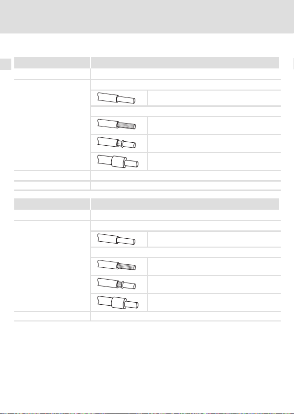
Cable cross−sections and screw−tightening torques
Field Values
Electrical connection Plug connector with double screw connection
Possible connections
Tightening torque 0.5 ... 0.6 Nm (4.4 ... 5.3 lb−in)
Stripping length 10 mm
rigid:
flexible:
2
1.5 mm
(AWG 16)
without wire end ferrule
2
(AWG 16)
1.5 mm
with wire end ferrule, without plastic sleeve
2
(AWG 16)
1.5 mm
with wire end ferrule, with plastic sleeve
2
(AWG 16)
1.5 mm
Field Values
Electrical connection 2−pin plug connector with spring connection
Possible connections
Stripping length 9 mm
rigid:
flexible:
2
1.5 mm
(AWG 16)
without wire end ferrule
2
(AWG 16)
1.5 mm
with wire end ferrule, without plastic sleeve
2
(AWG 16)
1.5 mm
with wire end ferrule, with plastic sleeve
2
(AWG 16)
1.5 mm
64
EDK82ZAFUC010 DE/EN/FR 4.0
Page 65

Commissioning
Before switching on
7 Commissioning
Before switching on
Stop!
Before switching on the standard device with the function module for the first
time, check...
ƒ the entire wiring with regard to completeness, short circuit, and earth
fault.
ƒ whether the bus system is terminated by a bus terminating resistor at the
physically first and last node.
7
Note!
A generally applicable description for commissioning function modules with a
CANopen communication profile using one of the numerous programs
available on the market cannot be provided within the scope of this
documentation.
Such a program is not included in Lenze’s scope of supply.
EDK82ZAFUC010 DE/EN/FR 4.0
65
Page 66

7 Commissioning
Commissioning steps
Commissioning steps
Note!
Do not change the setting sequence.
Step Description Detailed
1. Configure master system (CANopen master) for communication with
2. Inhibit standard device via terminal 28 (CINH).
3. Connect mains voltage and, if available, separate voltage supply of
4. Check status display.
the function module.
l Set terminal 28 to LOW level.
l Later the standard device can be inhibited and enabled via the
bus.
the function module.
l After approx. 1 second the standard device will be ready for
operation.
l Controller inhibit (CINH) is active.
Response
l The two−colored LED "Connection status to the standard device"
(
) is constantly illuminated with a green light .
l The LED "Status of the CANopen communication" () is blinking.
Precondition: Other nodes have to be already connected to the
bus.
l Keypad: (if plugged in)
information
69
Documentation
of the standard
device
73
74
66
EDK82ZAFUC010 DE/EN/FR 4.0
Page 67

Commissioning
Commissioning steps
7
DescriptionStep
5. A Set node address via ...
6.
7. Select function module as source for control commands and
8. Assign the process output words of the master to the process input
9. Assign the process output words of the standard device to the
10. Enable process output data of the master with C1512 = 65535.
– C1509 or
– DIP switches S1 ... S7.
B Set baud rate via ...
– C1516 or
– DIP switches S8 ... S10.
If the settings via code apply (DIP switches S1 ... S7 = OFF), the node
address and baud rate have to be newly assigned after a parameter
set transfer.
C Switch off the voltage supply of the function module and the
standard device and then switch it on again to accept the
changed settings.
The changes with regard to the node address and baud rate via
keypad will be effective immediately.
Communication with the standard device is now possible, i.e. all
codes can be read and all writable codes can be adapted to your
application.
Response
The LED "Status of CANopen communication" (
bus is active.
setpoints.
l Set C0005 = 200.
– A preconfiguration for operation with the function module is
carried out.
– Control words and status words are already linked.
words of the standard device via C1511, if necessary.
process input data of the master via C1510, if necessary.
Only required if C1511 has been altered.
) is blinking if the
Detailed
information
70
Documentation
of the standard
device
74
EDK82ZAFUC010 DE/EN/FR 4.0
67
Page 68

7 Commissioning
Commissioning steps
DescriptionStep
11.
12. Enable standard device via terminal 28 (CINH).
13. Select setpoint.
14. Now the drive starts.
15. Inhibit standard device.
The master system effects the change to the "Operational" state at
the function module.
Response
l The two−colored LED "Connection status to the standard device"
) is constantly illuminated with a green light.
(
l You can read (e.g. status word) or write setpoints (e.g. frequency
setpoint) via the PDOs.
l Set terminal 28 to HIGH level.
l The master sends the setpoint via the process output word
selected.
l Via the bus (e. g. control word bit 9), or
l Set terminal 28 (CINH) to LOW level.
Detailed
information
74
68
EDK82ZAFUC010 DE/EN/FR 4.0
Page 69

Configuring the host system (master)
Commissioning
Configuring the host system (master)
For communication with the function module, first the master system has to be configured.
Settings on the CANopen master
For configuring the CAN bus, the device description file (EDS file) of the communication
module has to be imported in the configuring software of the CANopen master.
The EDS file can be downloaded in the download area at http://www.Lenze.com.
7
EDK82ZAFUC010 DE/EN/FR 4.0
69
Page 70

7 Commissioning
Setting node address and baud rate
Setting node address and baud rate
Note!
Node address and baud rate can be set via DIP switches or codes.
ƒ Select an unambiguous node address between 1 and 63 for each device.
ƒ The baud rate must be set to the same value for all controllers and the
master computer.
ƒ If the DIP switches S1 ... S7 are in OFF position, the code settings for node
address/baud rate are active. If a DIP switch is set to ON, the node address
(C1509)/baud rate (C1516) will be overwritten with the corresponding
values of the switch positions.
Settings via codes
ƒ DIP switches S1 ... S7 = OFF (Lenze setting)
ƒ Set the node address via C1509.
ƒ Set the baud rate via C1516.
Settings via the DIP switches at the front
ƒ Set the node address via DIP switches S1 ... S7.
ƒ Set the baud rate via DIP switches S8 ... S10.
Accepting changed settings
ƒ Switch off the voltage supply of the function module and the controller
and then switch it on again to activate the changed settings.
70
EDK82ZAFUC010 DE/EN/FR 4.0
Page 71

Node address setting
Setting node address and baud rate
Commissioning
7
ON
1627438
Fig. 1 Address assignment via DIP switch
5
910
ON
OFF
Note!
If several controllers are connected to the network, the node addresses must
differ from each other.
ƒ If several devices are connected to the CAN network, the node addresses must differ
from each other.
ƒ The desired node address results from the sum of the values of switches (1 ... 7) in ON
position.
Example
Switch Value
164OFF
2 32 OFF
3 16 ON
4 8 OFF
5 4 ON
6 2 ON
7 1 ON
Switch position Node address
16 + 4 + 2 + 1 = 23
EDK82ZAFUC010 DE/EN/FR 4.0
71
Page 72

7 Commissioning
Setting node address and baud rate
Baud rate setting
ON
1627438
Fig. 2 Baud rate setting
5
910
ON
OFF
Note!
The baud rate must be set to the same value for all controllers and the master
computer.
Baud rate [kbps] S8 S9 S10
10 ON ON OFF
20 ON OFF ON
50 OFF ON ON
125 OFF ON OFF
250 OFF OFF ON
500 OFF OFF OFF
1000 ON OFF OFF
Automatic recognition ON ON ON
Automatic recognition of the baud rate
Note!
The baud rate can only be recognised automatically if other nodes are already
sending telegrams via the CAN bus without errors:
ƒ After switch−on or "Reset Node" the function module searches for the
correct baud rate by analysing the telegrams sent by the other nodes.
ƒ If the correct baud rate is recognised, it is accepted by the function module.
72
EDK82ZAFUC010 DE/EN/FR 4.0
Page 73

Connecting the mains voltage
Connecting the mains voltage
Note!
If the external voltage supply of the function module is used, switch it on as
well.
ƒ The standard device is ready for operation approx. 1 s after switching on the supply
voltage.
ƒ The controller inhibit is active.
ƒ The green LED at the front of the function module is lit.
Protection against uncontrolled start−up
Commissioning
7
Note!
Establishing communication
For establishing communication via an externally supplied function module,
the standard device must be switched on as well.
ƒ After communication has been established, the externally supplied module
is independent of the power on/off state of the standard device.
Protection against uncontrolled start−up
After a fault (e.g. short−term mains failure), a restart of the drive is not always
wanted and − in some cases − even not allowed.
The restart behaviour of the controller can be set in C0142:
ƒ C0142 = 0 (Lenze setting)
– The controller remains inhibited (even if the fault is no longer active).
– The drive starts in a controlled mode by explicitly enabling the
controller: LOW−HIGH edge at terminal 28 (CINH)
ƒ C0142 = 1
– An uncontrolled restart of the drive is possible.
EDK82ZAFUC010 DE/EN/FR 4.0
73
Page 74

8 Diagnostics
LED status displays
8 Diagnostics
LED status displays
LED
Pos. Colour Status
− off
green
red
Description
l The function module is not supplied with voltage.
l The external voltage supply is switched off.
blinking The function module is supplied with voltage but is not
on The function module is supplied with voltage and has a
blinking Error in the function module:
on Fatal error in the function module:
connected to the standard device.
Reason:
The standard device is ...
l switched off.
l in the initialisation phase.
l not available.
connection to the standard device.
l Parameter was reset to Lenze setting.
l CANopen operation is possible.
l CANopen operation is not possible.
E82ZAFU001C
74
EDK82ZAFUC010 DE/EN/FR 4.0
Page 75

LED
Pos. Colour / status
off
green
red
red
Description
Connection to master not established.
CANopen status ("S")
CANopen fault ("F")
S: bus off
Diagnostics
LED status displays
8
blinking fast (jittering)
blinking (green) every 0.2 s
blinking (green) every 0.2 s
blinking (red) 1 x, 1 s off
blinking (green) every 0.2 s
blinking (red) 2 x, 1 s off
on (green)
on (green)
blinking (red) 1 x, 1 s off
on (green)
blinking red 2 x, 1 s off
on (green)
3 x blinking red, 1 s off
blinking (green) once per
second
blinking (green) once per
second
blinking (red) 1 x, 1 s off
blinking (green) once per
second
blinking red 2 x, 1 s off
EDK82ZAFUC010 DE/EN/FR 4.0
Automatic baud rate recognition is active.
S: pre−operational, F: none
S: pre−operational, F: warning limit reached
S: pre−operational, F: node guard event
S: operational, F: none
S: operational, F: warning limit reached
S: operational, F: node guard event
S: operational, F: sync message error
S: stopped, F: none
S: stopped, F: warning limit reached
S: stopped, F: node guard event
75
Page 76

Légende de l’illustration de la page dépliante
Pos. Description Informations
Etat de la communication avec l’appareil de base (LED bicolore verte et rouge)
Etat de la liaison par bus (LED bicolore verte et rouge)
Interrupteurs DIP pour la configuration
l de l’adresse de nœud ("Address") ;
l de la vitesse de transmission ("Bd").
Bornier X3.1, raccordement de CANopen
Bornier X3.2, raccordement de l’alimentation externe
Bornier X3.3, raccordement
l du blocage variateur (CINH) ;
l de l’alimentation interne.
Plaque signalétique 85
0Fig. 0Tab. 0
détaillées
110
106
88
76
EDK82ZAFUC010 DE/EN/FR 4.0
Page 77

Sommaire i
1 Présentation du document 78 . . . . . . . . . . . . . . . . . . . . . . . . . . . . . . . . . . . . . . . . . . . .
Conventions utilisées 79 . . . . . . . . . . . . . . . . . . . . . . . . . . . . . . . . . . . . . . . . . . . . . . . . .
Consignes utilisées 80 . . . . . . . . . . . . . . . . . . . . . . . . . . . . . . . . . . . . . . . . . . . . . . . . . . .
2 Consignes de sécurité 82 . . . . . . . . . . . . . . . . . . . . . . . . . . . . . . . . . . . . . . . . . . . . . . . .
3 Description du produit 83 . . . . . . . . . . . . . . . . . . . . . . . . . . . . . . . . . . . . . . . . . . . . . . . .
Fonction 83 . . . . . . . . . . . . . . . . . . . . . . . . . . . . . . . . . . . . . . . . . . . . . . . . . . . . . . . . . . .
Utilisation conforme à la fonction 83 . . . . . . . . . . . . . . . . . . . . . . . . . . . . . . . . . . . . .
Equipement livré 84 . . . . . . . . . . . . . . . . . . . . . . . . . . . . . . . . . . . . . . . . . . . . . . . . . . . .
Identification 85 . . . . . . . . . . . . . . . . . . . . . . . . . . . . . . . . . . . . . . . . . . . . . . . . . . . . . . .
4 Spécifications techniques 86 . . . . . . . . . . . . . . . . . . . . . . . . . . . . . . . . . . . . . . . . . . . . .
Caractéristiques générales 86 . . . . . . . . . . . . . . . . . . . . . . . . . . . . . . . . . . . . . . . . . . . .
Conditions d’utilisation 86 . . . . . . . . . . . . . . . . . . . . . . . . . . . . . . . . . . . . . . . . . . . . . . .
Isolement de protection 87 . . . . . . . . . . . . . . . . . . . . . . . . . . . . . . . . . . . . . . . . . . . . . .
Spécifications des bornes de raccordement 88 . . . . . . . . . . . . . . . . . . . . . . . . . . . . . .
Encombrements 89 . . . . . . . . . . . . . . . . . . . . . . . . . . . . . . . . . . . . . . . . . . . . . . . . . . . . .
5 Installation mécanique 90 . . . . . . . . . . . . . . . . . . . . . . . . . . . . . . . . . . . . . . . . . . . . . . .
6 Installation électrique 91 . . . . . . . . . . . . . . . . . . . . . . . . . . . . . . . . . . . . . . . . . . . . . . . .
Utilisation de borniers 91 . . . . . . . . . . . . . . . . . . . . . . . . . . . . . . . . . . . . . . . . . . . . . . . .
Câblage conforme CEM 92 . . . . . . . . . . . . . . . . . . . . . . . . . . . . . . . . . . . . . . . . . . . . . . .
Raccordement à un maître 93 . . . . . . . . . . . . . . . . . . . . . . . . . . . . . . . . . . . . . . . . . . . .
Longueur de câble bus 94 . . . . . . . . . . . . . . . . . . . . . . . . . . . . . . . . . . . . . . . . . . . . . . .
Alimentation 97 . . . . . . . . . . . . . . . . . . . . . . . . . . . . . . . . . . . . . . . . . . . . . . . . . . . . . . .
Affectation des bornes de raccordement 99 . . . . . . . . . . . . . . . . . . . . . . . . . . . . . . . . .
Sections des câbles et couples de serrage des vis 100 . . . . . . . . . . . . . . . . . . . . . . . . . .
7 Mise en service 101 . . . . . . . . . . . . . . . . . . . . . . . . . . . . . . . . . . . . . . . . . . . . . . . . . . . . . .
Avant la première mise sous tension 101 . . . . . . . . . . . . . . . . . . . . . . . . . . . . . . . . . . . .
Etapes de mise en service 102 . . . . . . . . . . . . . . . . . . . . . . . . . . . . . . . . . . . . . . . . . . . . .
Configuration du maître 105 . . . . . . . . . . . . . . . . . . . . . . . . . . . . . . . . . . . . . . . . . . . . .
Réglage de l’adresse de noeud et de la vitesse de transmission 106 . . . . . . . . . . . . .
Mise sous tension 109 . . . . . . . . . . . . . . . . . . . . . . . . . . . . . . . . . . . . . . . . . . . . . . . . . . . .
8 Diagnostic 110 . . . . . . . . . . . . . . . . . . . . . . . . . . . . . . . . . . . . . . . . . . . . . . . . . . . . . . . . . .
Affichages d’état par LED 110 . . . . . . . . . . . . . . . . . . . . . . . . . . . . . . . . . . . . . . . . . . . . .
EDK82ZAFUC010 DE/EN/FR 4.0
77
Page 78

1 Présentation du document
1 Présentation du document
Contenu
La présente documentation contient ...
ƒ des consignes de sécurité à respecter impérativement ;
ƒ les valeurs indiquées concernant les versions des appareils de base Lenze à utiliser ;
ƒ des informations sur l’installation mécanique et électrique du module de fonction ;
ƒ des informations sur la mise en service du module de fonction ;
ƒ les spécifications techniques.
Validité
Les informations contenues dans le présent document s’appliquent aux appareils suivants :
Module de fonction Référence de
CANopen PT E82ZAFUC010 1x 1x
Public visé
Ce document est destiné aux personnes chargées d’installer et de mettre en service le
produit décrit selon les exigences du projet.
commande
A partir de la version
matérielle
A partir de la version
logicielle
Conseil !
Toutes les informations relatives aux produits Lenze peuvent être téléchargées
sur notre site à l’adresse suivante :
http://www.Lenze.com
78
EDK82ZAFUC010 DE/EN/FR 4.0
Page 79

Présentation du document
Conventions utilisées
Conventions utilisées
Pour distinguer les différents types d’information, cette documentation utilise les
conventions suivantes :
Type d’information Aperçu Exemples/remarques
Représentation des chiffres
Séparateur décimal
Symboles
Renvoi à une page
Point Le point décimal est généralement
utilisé.
Exemple : 1234.56
Renvoi à une autre page présentant
des informations supplémentaires
Exemple : 16 = voir page 16
1
EDK82ZAFUC010 DE/EN/FR 4.0
79
Page 80

1 Présentation du document
Consignes utilisées
Consignes utilisées
Pour indiquer des risques et des informations importantes, la présente documentation
utilise les mots et symboles suivants :
Consignes de sécurité
Présentation des consignes de sécurité
Danger !
(Le pictogramme indique le type de risque.)
Explication
(L’explication décrit le risque et les moyens de l’éviter.)
Pictogramme et mot associé Explication
Situation dangereuse pour les personnes en raison d’une
tension électrique élevée
Danger !
Danger !
Stop !
Indication d’un danger imminent qui peut avoir pour
conséquences des blessures mortelles ou très graves en
cas de non−respect des consignes de sécurité
correspondantes
Situation dangereuse pour les personnes en raison d’un
danger d’ordre général
Indication d’un danger imminent qui peut avoir pour
conséquences des blessures mortelles ou très graves en
cas de non−respect des consignes de sécurité
correspondantes
Risques de dégâts matériels
Indication d’un risque potentiel qui peut avoir pour
conséquences des dégâts matériels en cas de non−respect
des consignes de sécurité correspondantes
80
EDK82ZAFUC010 DE/EN/FR 4.0
Page 81

Consignes d’utilisation
Pictogramme et mot associé Explication
Présentation du document
Consignes utilisées
1
Remarque
importante !
Conseil !
Remarque importante pour assurer un fonctionnement
correct
Conseil utile pour faciliter la mise en uvre
Renvoi à une autre documentation
EDK82ZAFUC010 DE/EN/FR 4.0
81
Page 82

2 Consignes de sécurité
2 Consignes de sécurité
Danger !
Toute utilisation contre−indiquée du module de fonction et de l’appareil de
base peut entraîner des blessures graves et des dommages matériels.
Tenir compte des consignes de sécurité et des dangers résiduels énoncés dans
la documentation de l’appareil de base.
Stop !
Décharges électrostatiques
Les décharges électrostatiques peuvent endommager ou détruire les
composants électroniques situés à l’intérieur du module de fonction.
Risques encourus :
ƒ Module de fonction en panne
ƒ La communication par bus de terrain est impossible ou erronée.
Mesures de protection :
ƒ Se débarrasser impérativement de toute charge électrostatique avant
toute intervention du le module.
82
EDK82ZAFUC010 DE/EN/FR 4.0
Page 83

Description du produit
Fonction
3 Description du produit
Fonction
Le module de fonction est utilisé pour coupler les convertisseurs de fréquence Lenze avec le
système de communication CANopen.
Utilisation conforme à la fonction
Le module de fonction...
ƒ est un accessoire compatible avec les appareils de base Lenze suivants :
Série d’appareils Référence de commande A partir de la version matérielle
Convertisseurs de fréquence 8200 vector Vx14
ƒ est un équipement de production destiné à être utilisé dans des installations
industrielles haute tension.
Toute autre utilisation est contre−indiquée !
Conseil !
Pour de plus amples renseignements sur ce module de fonction, se reporter au
manuel de communication correspondant.
Celui−ci est disponible au format PDF et peut être téléchargé à l’adresse
suivante (zone de téléchargement) :
http://www.Lenze.com
3
EDK82ZAFUC010 DE/EN/FR 4.0
83
Page 84

3 Description du produit
Equipement livré
Equipement livré
Pos. Equipement livré
Module de fonction E82ZAFUC010
Instructions de montage
Bornier double à raccordement par vis, à 3 bornes
Bornier double à raccordement par vis, à 2 bornes
Bornier à lame ressort, à 4 bornes
Etrier de fixation
Résistances d’extrémité de bus (de 120 W chacune)
E82ZAFU001C, E82ZAFX007, 016−019
84
EDK82ZAFUC010 DE/EN/FR 4.0
Page 85
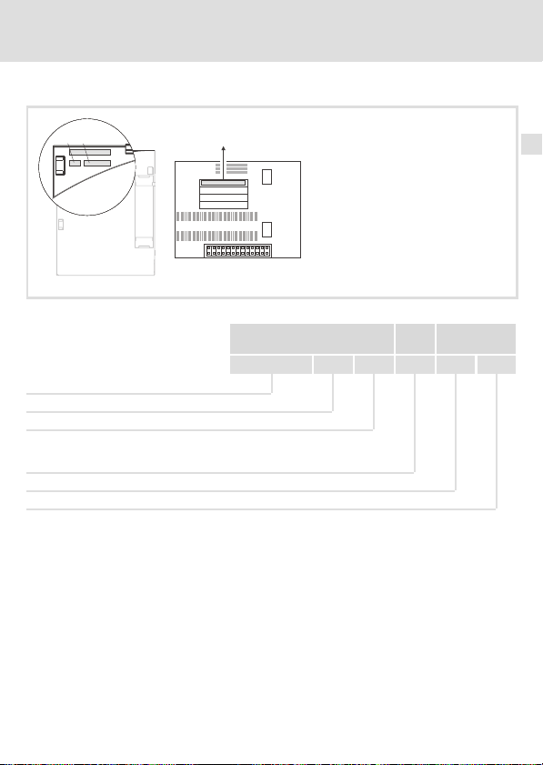
Identification
APPLICATION
010 / 3A22
Description du produit
Identification
3
APPLICATION
010/ 3A22
Série d’appareils
CANopen
Génération d’appareils
Variante : PT (Plug Terminal) avec
raccordement par lame ressort et
fixation par vis
Version matérielle
Version logicielle
L
Type
Id.-No.
Prod.-No.
Ser.-No.
E82AF000P0B201XX
E82ZAFX005
E82ZAF U C 010 1x 1x
EDK82ZAFUC010 DE/EN/FR 4.0
85
Page 86

4 Spécifications techniques
Caractéristiques générales
4 Spécifications techniques
Caractéristiques générales
Domaine Valeurs
Référence de commande E82ZAFUC010
Profil de communication CANopen, DS301 V4.02
Support de communication DIN ISO 11898
Topologie du réseau
Adresses des nœuds réglables 127 maxi (avec répétiteur)
Nombre de participants
possible par segment
Participant au bus CANopen Esclave
Vitesse de transmission
[kbits/s]
Mots de données process 1 à 12 mots
Conditions d’utilisation
Conditions ambiantes
Conditions climatiques
Stockage
Transport CEI/EN 60721−3−2 2K3 (−25 ... +70 °C)
Fonctionnement Conformément aux données de l’appareil de base Lenze utilisé (voir la
Pollution ambiante
admissible
Indice de protection IP20 (protection contre contacts accidentels selon NEMA 250 type 1)
Fermée des deux extrémités par une résistance de 120 W
l Pour les participants E82ZAFUC010 : 106 maxi
l Pour des participants différents :
voir remarques sur le fonctionnement mixte 95
10, 20, 50, 125, 250, 500, 1000
CEI/EN 60721−3−1 1K3 (−25 ... +60 °C)
documentation de l’appareil de base).
EN 61800−5−1 Degré de pollution 2
86
EDK82ZAFUC010 DE/EN/FR 4.0
Page 87

Spécifications techniques
Isolement de protection
Isolement de protection
Isolation entre le bus et ... Type d’isolement (selon EN 61800−5−1)
l la partie puissance 8200 vector
l le point de terre/PE (X3.2/7, X3.3/7)
l l’alimentation externe (X3/2/59)
l l’alimentation pour CINH (X3/3/20)
l la borne de blocage variateur, CINH (X3/3/28)
Isolement renforcé
Isolement fonctionnel
Isolement fonctionnel
Isolement fonctionnel
Isolement fonctionnel
4
EDK82ZAFUC010 DE/EN/FR 4.0
87
Page 88

4 Spécifications techniques
Spécifications des bornes de raccordement
Spécifications des bornes de raccordement
Borne
X3.1/
CG CAN−GND Potentiel de référence pour CAN
CL CAN−LOW Ligne de données CAN (LOW) (BAS)
CH CAN−HIGH Ligne de données CAN (HIGH) (HAUT)
Désignation Fonction/Niveau
Borne
X3.2/
59 Alimentation CC externe du module de fonction
7 GND1 Potentiel de référence pour X3.3/20
Borne
X3.3/
7 GND1 Potentiel de référence pour X3.3/20
39 GND2 Potentiel de référence 2 du blocage variateur (CINH) sur X3.3/28
28 CINH Blocage variateur
20 Source de tension CC pour l’alimentation externe du blocage
88
Désignation Fonction/Niveau
Désignation Fonction/Niveau
l +24VCC±10 % (référence : GND1)
l Courant absorbé de 24 V CC : 80 mA
Courant max. admissible dans la borne 59 lors du bouclage de
l’alimentation des autres participants au bus : 3 A.
l Résistance d’entrée : 3,3 kW
l Marche = HAUT (+12 V à +30 V)
l Arrêt = BAS (0 à +3 V)
(référence : GND2)
variateur (CINH)
l +20 V (référence : GND1)
l I
= 10 mA
max
EDK82ZAFUC010 DE/EN/FR 4.0
Page 89

Encombrements
Toutes les cotes en mm
Spécifications techniques
Encombrements
E82ZAFU001A
4
EDK82ZAFUC010 DE/EN/FR 4.0
89
Page 90

5 Installation mécanique
5 Installation mécanique
Pour l’installation mécanique du module de fonction, suivre les consignes fournies dans les
instructions de montage de l’appareil de base.
Les instructions de montage de l’appareil de base ...
ƒ font partie de la livraison standard et sont comprises dans l’emballage.
ƒ contiennent des consignes pour éviter des dommages dus à un emploi
contre−indiqué.
ƒ décrivent l’ordre à respecter pour les opérations d’installation.
90
EDK82ZAFUC010 DE/EN/FR 4.0
Page 91

Installation électrique
Utilisation de borniers
6 Installation électrique
Utilisation de borniers
Stop !
Pour éviter d’endommager les borniers et les contacts :
ƒ Enficher et retirer les borniers uniquement lorsque le variateur est coupé
du réseau.
ƒ Procéder au câblage des borniers avant de les enficher.
ƒ Enficher également des borniers non affectés.
Utilisation de borniers à lame ressort
6
E82ZAFX013
EDK82ZAFUC010 DE/EN/FR 4.0
91
Page 92

6 Installation électrique
Câblage conforme CEM
Câblage conforme CEM
Pour s’assurer que le câblage est conforme aux exigences à respecter en matière de CEM,
vérifier les points suivants :
Remarque importante !
ƒ Séparer physiquement les câbles de commande/de données des câbles
moteur.
ƒ Pour les signaux numériques, blinder les câbles de commande et de
données aux deux extrémités.
ƒ Pour éviter les différences de potentiel entre les participants au bus, utiliser
une ligne de compensation d’une section minimale de 16mm
PE).
ƒ Respecter les autres consignes relatives à un câblage conforme CEM
fournies dans la documentation de l’appareil de base.
Procédure à suivre pour le câblage
1. Respecter la topologie de bus : ne pas utiliser de câbles de dérivation.
2. Respecter les indications et prescriptions concernant le câblage fournies dans la
documentation du système de commande.
3. Utiliser uniquement des câbles correspondant aux spécifications fournies (93).
4. Respecter la longueur de câble bus max. admissible (94)
5. Connecter des résistances d’extrémité de bus de 120 W chacune (comprises dans la
livraison) :
– uniquement entre le premier et le dernier participant au bus (extrémités
physiques) ;
– entre les bornes CAN−LOW (BAS) et CAN−HIGH (HAUT).
.
2
(référence :
92
EDK82ZAFUC010 DE/EN/FR 4.0
Page 93

Installation électrique
Raccordement à un maître
Raccordement à un maître
Le schéma ci−dessous illustre le placement des câbles CAN jusqu’au module de fonction :
8200 vector
8200 vector
SPS/PC
6
E82ZAFUC010
CG CG
CL CL
+
Les convertisseurs de fréquence de série 8200 vector/8200 motec avec modules de fonction
enfichables communiquent avec le maître CANopen via CANopen.
Spécifications pour câble de transmission
Il est recommandé d’utiliser des câbles CAN conformes à la norme ISO 11898−2 :
Câbles CAN conformes à la norme ISO 11898−2
Type de câble Paire blindée
Impédance
Résistance / section de câble
Temps de parcours du signal
CH CH
120
Longueur de câble £ 300 m £ 70 mW/m / 0.25 0.34 mm2 (AWG22)
Longueur de câble 301 1000 m
E82ZAFUC010
+
120 W (95 ... 140 W)
£ 40 mW/m / 0.5 mm
£ 5 ns/m
+
2
(AWG20)
GND
120
LOW
HIGH
E82ZAFU015
EDK82ZAFUC010 DE/EN/FR 4.0
93
Page 94

6 Installation électrique
Longueur de câble bus
Longueur de câble bus
Remarque importante !
Respecter impérativement les longueurs de câble autorisées !
1. Vérifier la longueur totale de câble admise dans le Tab. 1.
La longueur totale de câble est déterminée par la vitesse de transmission.
Vitesse de transmission
[kbits/s]
10 8000
20 3900
50 1500
125 630
250 290
500 120
1000 25
Tab. 1 Longueur totale de câble
2. Vérifier la longueur totale de câble admise par segment dans le Tab. 2.
La longueur de câble par segment est déterminée par la section de câble utilisée et le
nombre de participants par segment. Sans répétiteur, la longueur de câble par segment
équivaut à la longueur totale de câble.
Nombre de
participants max.
par segment
2 240 m 430 m 650 m 940 m
5 230 m 420 m 640 m 920 m
10 230 m 410 m 620 m 900 m
20 210 m 390 m 580 m 850 m
32 200 m 360 m 550 m 800 m
63 170 m 310 m 470 m 690 m
100 150 m 270 m 410 m 600 m
Tab. 2 Longueur de câble par segment
Section de câble
0,25 mm
Longueur totale de câble [m]
2
0,5 mm
2
0,75 mm
2
1,0 mm
2
94
EDK82ZAFUC010 DE/EN/FR 4.0
Page 95

Installation électrique
Longueur de câble bus
3. Comparer les valeurs déterminées.
Si la valeur établie à partir du Tab. 2 est inférieure à la longueur totale de câble à réaliser
d’après le Tab. 1, il est nécessaire d’avoir recours à des répétiteurs. Les répétiteurs divisent
la longueur totale de câble en segments.
Remarque importante !
ƒ Tenir compte de la réduction de la longueur totale de câble, due à la
temporisation des signaux du répétiteur (voir exemple
ƒ Fonctionnement mixte
– Il y a fonctionnement mixte lorsque des participants différents sont
raccordés à un même réseau.
– Si la longueur totale de câble pour les différents participants varie,
malgré une vitesse de transmission identique, la longueur de câble
maximale doit être déterminée sur la base de la plus petite valeur.
Exemple : aide à la sélection
Caractéristiques
l Section de câble :
l Nombre de
participants :
l Répétiteurs :
Tout en tenant compte de la configuration requise, il convient de respecter les longueurs de
câble/nombre de répétiteurs suivants :
Vitesse de transmission
[kbits/s]
Longueur de câble max. [m] 8000 3900 1500 630 290 120 25
Longueur de câble par
segment [m]
Nombre de répétiteurs 33 16 6 2 − − −
2
(conformément aux spécifications du câble fournies 93)
0,5 mm
100
Répétiteurs Lenze de type 2176 (réduction de la longueur de câble :
30 m)
10 20 50 125 250 500 1000
270 270 270 270 290 120 25
96).
6
EDK82ZAFUC010 DE/EN/FR 4.0
95
Page 96

6 Installation électrique
Longueur de câble bus
Utilisation d’un répétiteur
Caractéristiques
2
125 kbits/s
2
0,5 mm
28
1500 m
câble
360 m Tab. 2
l Vitesse de transmission
l Section de câble :
l Nombre de
participants :
l Longueur de câble :
Etapes de contrôle Longueur de
1. Longueur de câble totale pour 125 kbits/s 630 m Tab. 1
2. Longueur de câble par segment, pour 28 participants et une
section de 0,5 mm
3. Analyse comparative : la valeur indiquée au point 2 est inférieure à la longueur de câble
nécessaire, qui est de 1500 m.
Conclusion
l Sans répétiteur, la longueur de câble nécessaire (1500 m) ne peut être réalisée.
l Au−delà de 360 m (point 2.), il faut utiliser un répétiteur.
Résultat
l Répétiteur utilisé : répétiteur Lenze 2176 (réduction de la longueur de câble : 30 m).
l Calcul de la longueur de câble maxi. pour
– le premier segment : 360 m
– le deuxième segment et les suivants : 360 m (selon Tab. 1) moins 30 m (réduction de la
longueur de câble en cas d’utilisation d’un répétiteur)
à Longueur de câble maxi possible avec quatre répétiteurs : 1680 m.
à La longueur de câble requise peut donc être réalisée.
Voir
Remarque importante !
L’utilisation d’un deuxième répétiteur est recommandée en tant que :
ƒ interface de service
Avantage : couplage possible sans interrompre le fonctionnement par bus.
ƒ interface de mesure
Avantage : l’appareil de mesure/de programmation reste isolé
galvaniquement.
96
EDK82ZAFUC010 DE/EN/FR 4.0
Page 97

Installation électrique
Alimentation
Alimentation
Alimentation de la borne de blocage variateur (CINH) via source de tension interne (X3.3/20)
6
GND1
CH 7
CL
CG
X3.1 X3.2 X3.3
CAN-GND
CAN-LOW
CAN-HIGH
Alimentation de la borne de blocage variateur (CINH) via source de tension externe
CH 7
CL
CG
X3.1 X3.2 X3.3
CAN-GND
CAN-LOW
CAN-HIGH
59
GND1
59
GND2
GND2
_
+
20 V
28397
20
E82ZAFU011
20 V
28397
20
E82ZAFU012
EDK82ZAFUC010 DE/EN/FR 4.0
97
Page 98

6 Installation électrique
Alimentation
Alimentation du module de fonction et de la borne de blocage variateur (CINH) via source de tension
externe
GND1
CH 7
CL
CG
X3.1 X3.2 X3.3
59
_
+
CAN-GND
CAN-LOW
CAN-HIGH
Câblage minimal nécessaire au fonctionnement
GND2
_
+
20 V
20
28397
E82ZAFU013
98
EDK82ZAFUC010 DE/EN/FR 4.0
Page 99

Affectation des bornes de raccordement
Installation électrique
Affectation des bornes de raccordement
Borne
X3.1/
CG CAN−GND Potentiel de référence pour CAN
CL CAN−LOW Ligne de données CAN (LOW) (BAS)
CH CAN−HIGH Ligne de données CAN (HIGH) (HAUT)
Désignation Fonction/Niveau
6
Borne
X3.2/
59 Alimentation CC externe du module de fonction
7 GND1 Potentiel de référence pour X3.3/20
Borne
X3.3/
7 GND1 Potentiel de référence pour X3.3/20
39 GND2 Potentiel de référence 2 du blocage variateur (CINH) sur X3.3/28
28 CINH Blocage variateur
20 Source de tension CC pour l’alimentation externe du blocage
EDK82ZAFUC010 DE/EN/FR 4.0
Désignation Fonction/Niveau
l +24VCC±10 % (référence : GND1)
l Courant absorbé de 24 V CC : 80 mA
Courant max. admissible dans la borne 59 lors du bouclage de
l’alimentation des autres participants au bus : 3 A.
Désignation Fonction/Niveau
l Résistance d’entrée : 3,3 kW
l Marche = HAUT (+12 V à +30 V)
l Arrêt = BAS (0 à +3 V)
(référence : GND2)
variateur (CINH)
l +20 V (référence : GND1)
l I
= 10 mA
max
99
Page 100

6 Installation électrique
Sections des câbles et couples de serrage des vis
Domaine Valeurs
Raccordement électrique Bornier double, à raccordement par vis
Raccordements possibles
Couple de serrage 0.5 ... 0.6 Nm (4.4 ... 5.3 lb−in)
Fil dénudé 10 mm
rigide :
flexible :
2
1.5 mm
(AWG 16)
sans embout
2
(AWG 16)
1.5 mm
avec embout, sans gaine plastifiée
2
(AWG 16)
1.5 mm
avec embout et gaine plastifiée
2
(AWG 16)
1.5 mm
Domaine Valeurs
Raccordement électrique Bornier à lame ressort 2 bornes
Possibilités de
raccordement
Longueur du fil dénudé 9 mm
Fixe :
Souple :
2
1.5 mm
(AWG 16)
sans embout
2
(AWG 16)
1.5 mm
avec embout, sans cosse en plastique
2
(AWG 16)
1.5 mm
avec embout et cosse en plastique
2
(AWG 16)
1.5 mm
100
EDK82ZAFUC010 DE/EN/FR 4.0
 Loading...