

Page 1

EDB9200_E/GB
S
9
00375316
Antriebstechnik
Operating Instructions
ervo controller
200 series
Page 2

These Operating Instructions are valid for the controllers with the nameplate data:
9212 E.5x
9215 E.5x
9217 E.5x
9222 E.5x.5x
9223 E.5x.5x
9224 E.5x.5x
9225 E.5x.5x
9226 E.5x.5x
9227 E.5x.5x
9228 E.5x.5x
Controller type
Enclosure IP20
Hardware version + index
Software version + index
Corresponds to the German edition of 05/18/1995
Edition of: 05/18/1995
Date of print: 05/29/1995
Page 3

How to use these Operating
Instructions...
These Operating Instructions are divided into three parts:
•
Planning and installation
This part comprises the technical data of the supply modules,
the axis modules and of accessories available for the 9200
series (e. g. motors), instructions for installation and wiring and
descriptions of the drive connections.
•
Parameter setting
Describes the basics of parameter setting and informs about
commissioning, important functions and the operation via serial
interface. At the end of this part you will find a comprehensive
code table and a signal flow chart.
•
Service
Explains error messages and gives hints for trouble-shooting.
To locate information on specific topics, simply refer to the table of
contents at the beginning and to the index at the end of the
operating instructions.
A series of different symbols provide quick reference and highlight
important items.
Note
This symbol refers to items of information intended to facilitate
operation.
Caution
Notes which should be observed to avoid possible damage to or
destruction of equipment.
Warning
Notes which should be observed to avoid health risks to the
operating personnel.
Fehler! Es
ist nicht
möglich,
durch die
1
Page 4

Safety information
for electrical equipment used in industrial power installations.
The electrical devices and machines described are equipment to be
used in industrial power installations. This equipment incorporates
hazardous parts that are live, moving or rotating during operation.
Severe personal injury or damage to equipment may occur if e. g.
any required enclosures or covers are inappropriately removed or
the equipment is insufficiently serviced.
The personnel responsible for the safety of the equipment must
therefore ensure that:
•
only qualified personnel are permitted to install, operate and
maintain the devices
•
these Operating Instructions and any other documentation
about the equipment are consequently observed and always
available to the personnel working with the equipment.
•
non-qualified personnel is prohibited from working with the
equipment or in its vicinity.
•
the system is installed in accordance with local regulations.
A qualified person must by training be familiar with all relevant
standards and safety regulations and therefore be authorized to
perform the required work (For further details cf. IEC 364).
These safety instructions do not claim to be exhaustive. Should any
questions or problems occur, please contact your nearest Lenze
representative.
The information given in these Operating Instructions refer to the
specified hardware and software versions of the equipment.
The specifications, processes and ciruitry described in these
Operating Instructions are for guidance only and must be adapted
to your specific application.
Lenze cannot be held responsible for the applicability of the
processes and circuitry indicated.
The specifications in these Operating Instructions describe, not
guarantee the features of the equipment.
Hardware, software and documentation of the equipment have
been carefully checked by Lenze. Faultlessness cannot be
guaranteed.
Subject to technical alterations.
2
Page 5

Content
Planning and Installation
1. Features 5
2. Technical data 6
2.1. General data 6
2.2. Unit-specific data 6
2.2.1. Rated data of supply modules 6
2.2.2. Rated data of axis modules 7
2.3. Dimensions 8
2.4. Extension of delivery 8
2.5. Application as directed 8
2.6. Manufacturer's certification 9
3. Installation 10
3.1. Mechanical installation 10
3.2. Electrical installation 11
3.2.1. Combination of several axis modules with one supply module 12
3.2.2. Screening and earthing 14
3.2.3. Radio interference suppression 16
4. Drive connections 17
4.1. Power connections 17
4.1.1. Mains and motor connection 17
4.1.2. External brake resistor 18
4.2. Control connections of supply module 20
4.2.1. Overheat of internal brake resistor (9210 X1) 20
4.2.2. Mains and DC-bus monitoring (9210 X3) 20
4.2.3. State bus 21
4.3. Control connections axis module 22
4.3.1. Control terminals 22
4.3.2. Analog input and outputs 22
4.3.3. Digital inputs and outputs 23
5. Application examples 26
5.1. Variant with integrated positioning module 2211PP 26
5.2. Wiring with positioning control SX-1 28
5.2.1. Diagram 1: Mains supply 28
5.2.2. Diagram 2: Control circuit 230V 29
5.2.3. Diagram 3: Control circuit 24V 30
5.2.4. Diagram 4: Control connections 9200 - SX1 31
5.2.5. Diagram 5: Control connections SX1 32
6. Accessories 33
6.1. External brake resistors 33
6.2. Mains chokes 33
6.3. RFI filter 34
6.4. External fuses 34
6.5. System cables 34
6.5.1. System cables for control terminal block X5 34
6.5.2. System cables for master frequency selection X2 and incremental encoder output
X4 35
6.5.3. System cables for resolver X3 36
6.5.4. System cables for power supply of servo motors 37
6.5.5. System calbes for supply fo fan and brake 38
6.6. Motors 39
3
Page 6

1. LCD display 40
1.1. Key functions 40
1.2. Plain-text display 40
2. Basics of parameter setting 41
2.1. Change parameters 41
2.2. Save parameters 42
2.3. Load parameter 42
2.4. Examples 43
3. Commissioning 45
3.1. Basic parameter setting 45
3.2. Input of motor nameplate data 47
3.3. Setting of operating parameters 48
4. Additional functions 50
4.1. Mains failure detection with DC-bus control 50
4.1.1. Requirements 50
4.1.1. Wiring 52
4.1.2. Setting 53
4.2. Homing mode 56
4.3. Further additional functions 57
5. Serial interfaces 58
5.1. LECOM1 interface X1 58
5.2. LECOM status messages 59
5.3. Table of attributes 60
6. Code table 63
7. Signal flow chart axis modules 72
1. Monitoring messages 74
1.1. Monitoring without activating pulse inhibit 74
1.2. Monitoring with activating pulse inhibit 74
1.3. Monitoring with TRIP setting 74
2. LED displays 78
2.1. LED supply module 78
2.2. LED axis module 78
3. Checking the power stage 79
3.1. Checking the mains rectifier 79
3.2. Checking the output stage 79
Index
4
83
Page 7

Planning and installation
1. Features
The 9200 controller series comprises 3 supply modules (types
9212, 9215 and 9217) and 7 servo modules (types 9222-9228 with
motor peak currents ranging from 8 to 82 A) for asynchronous
servo motors.
•
Digital control by 16-bit microcontroller and 3 ASICs
•
Field-orientated vector controlled current
•
Four-quadrant operation, any speed and torque direction
•
Inverter with IGBTs
•
Selectable chopper frequency either low noise 8kHz or silent
16kHz
•
Supply and axis modules can be combined for single or multiaxis operation
•
Efficient energy exchange by means of DC-bus for multi-axis
operation
•
Controlled operation even during mains interruption.
•
Supply modules with integrated brake chopper and brake
resistors
•
Short-circuit protected inverter outputs
•
When using the specified mains chokes, the units comply with
the overvoltage class 2 according to VDE 0160
•
I x t monitoring as overload protection for the inverter
•
Parameter setting and diagnosis via keypad and 2-line LCD
display in plain text German, English, and French language
•
Control parameters can be modified ON-LINE
•
Isolated digital inputs and outputs for 24V-PLC level
•
Electronic incremental encoder simulation for use by other
drives
•
Master frequency input for positioning, master/slave operation
or angular synchronization
•
Drift free standstill in the case of master frequency input or
quick stop QSP
•
Serial interface LECOM A/B (RS232 and RS 485) for
parameter setting, control and diagnosis
•
Enclosure IP20
•
Variants with additional modules are available
•
Approvals: UL 508, File no. 132659
VDE 0160, VDE reg. no. 1799
5
Page 8

2. Technical data
2.1. General data
Enclosure
Noise immunity:
Influence of installation height on
rated current:
Ambient temperature
Permissible humidity
Permissible pollution
Steel sheet housing, IP20 to DIN 40050
Severity 4 to IEC 801-4
1000 m: 100% rated current
2000 m: 95% rated current
3000 m: 90% rated current
4000 m: 85% rated current
0 °C...+45 °C during operation
-25 °C...+55 °C during storage
-25 °C...+70 °C during transport
relative humidity 80%, no condensation
Pollution strength 2 to V DE 0110, part 2.
Do not expose units to corrosive or explosive gases .
2.2. Unit-specific data
2.2.1. Rated data of supply modules
Supply module type 9212_E 9215_E 9217_E
Order no. 33.9212_E 33.9215_E 33.9217_E
Mains voltage
DC-bus voltage
(at rated current)
Mains current
Permanent power
(at V
Peak power
(t=5 s)
Permanent brake power (with int.
brake resistor)
Permanent brake power (with
appropriate ext. brake resistor)
Peak brake power
with int. or ext. brake resistor
min. permissible resistance for int.
or ext. brake resistor
Power loss (without brake resistor)
Weight
mains
= 3 x 480 V)
1)
[V] 3 x 480; 50 - 60 Hz
permissible range 3 x 330...528 ± 0%;
[V] 1.35 x V
[A
]
eff
[kW] 4.9 16.5 33
[kW] 12 37 60
[W] 250
[kW] 4.9 16.5 33
[kW] 19.4 51.1 66.1
[Ω]
[W] 110 110 110
[kg] 9.0 10.5 11.0
62040
29 11 8.5
mains
1)
With low mains voltages , the permissible permanent power is reduced to P
zul
6
= P
V
⋅
n
mains
/ 480 V
Page 9
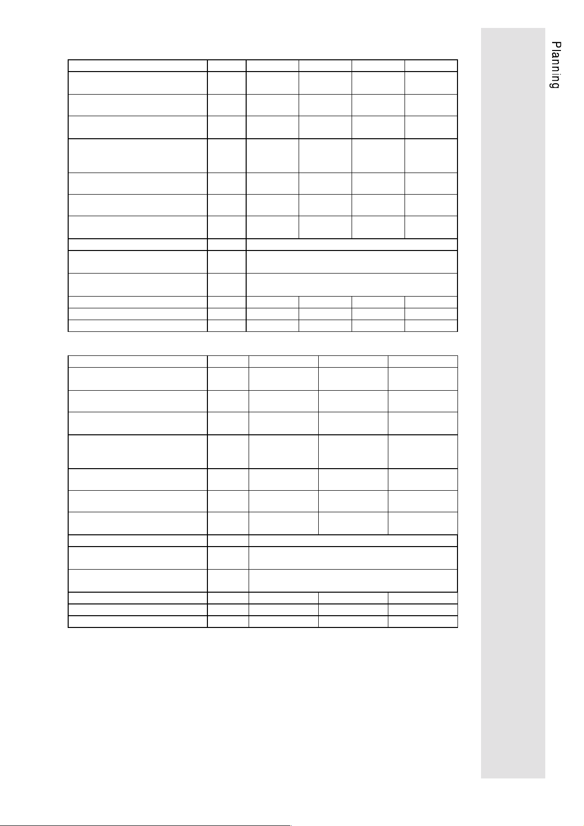
2.2.2. Rated data of axis modules
Axis module type 9222_E 9223_E 9224_E 9225_E
Order no. 33.9222_E 33.9223_E 33.9224_E 33. 9225_E
Output current
(f
= 8 kHz)
ch
Output current
= 16 kHz)
(f
ch
Peak current
(for t = 5 s at f
for t = 2.5 s at f
= 8 kHz;
ch
= 16 kHz)
ch
Permanent power
(V
= 3 x 480 V and f
A
= 8 kHz)
ch
Permanent power
(V
= 3 x 480 V and f
A
= 16 kHz)
ch
Peak power
= 3 x 480 V)
(V
A
Output voltage V
A
Field frequency
Speed
Power loss at permanent power
Power loss at controller inhibit
Weight
] 4.5 5.5 13.5 18
[A
eff
] 2.3 2.9 6.9 9.5
[A
eff
[A
] 8 10 24 33
eff
[kVA] 3.7 4.5 11.2 14.9
[kVA] 1.9 2.4 5.7 7.9
[kVA] 6.6 8.3 19.9 27.4
[V] 3 x 0...V
mains
[Hz] 0... ± 300
-1
] 0... ± 8000
[min
[W] 200 250 340 510
[W]454545125
[kg] 9.2 9.5 9.5 20.5
Type 9226_E 9227_E 9228_E
Order no. 33.9226_E 33.9227_E 33.9228_E
Output current
(f
= 8 kHz)
ch
Output current
= 16 kHz)
(f
ch
Peak current
(for t = 5s at f
for t = 2.5 s at f
= 8kHz;
ch
ch
= 16kHz)
Permanent power
(V
= 3 x 480 V and f
A
= 8 kHz)
ch
Permanent power
(V
= 3 x 480 V and f
A
= 16 kHz)
ch
Peak power
= 3 x 480 V)
(V
A
Output voltage V
A
Field frequency
Speed
Power loss at permanent power
Power loss at controller inhibit
Weight
[A
]25 32 46
eff
] 13 16.5 23.5
[A
eff
[A
]45 57 82
eff
[kVA] 20.2 26.6 38.2
[kVA] 10.8 13.7 19.5
[kVA] 37.4 47.3 68.1
[V] 3 x 0...V
mains
[Hz] 0... ± 300
-1
] 0... ± 8000
[min
[W] 640 800 1000
[W] 125 125 125
[kg] 21 22 22
7
Page 10
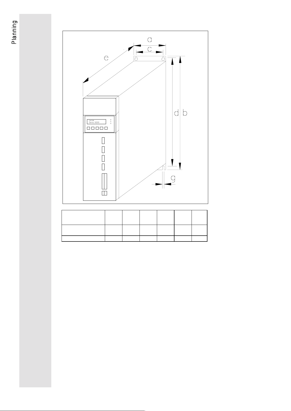
2.3. Dimensions
Type a
[mm]b[mm]c[mm]d[mm]e[mm]g[mm]
9212 - 9217
9222 - 9224
9225 - 9228
125 440 95 425 300 5
290 440 250 425 300 5
2.4. Extension of delivery
Axis module or supply module
•
Accessory kit (busbars, State-bus line, control terminals)
•
Operating Instructions
•
2.5. Application as directed
The units of the 9200 series are electrical units which are designed
for the application in control cabinets in industrial power
installations. They are designed for variable speed operations with
three-phase AC motors.
8
Page 11

2.6. Manufacturer's certification
We hereby certify that the below listed electronic controllers are
control components for variable speed motors intended for the
assembly into machines or together with other components to form
a machine. According to the "Council directive ... relating to
machinery" 89/392/EWG, our controllers are no machines.
The Operating Instructions supplied together with the controllers
give advice and recommendations for the installation and use of the
electronic equipment.
As long as the conformity with the protection and safety
requirements of the "Council directive ... relating to machinery"
89/392/EWG and its amendment 91/368/EWG is not proved,
operation of the machine is prohibited.
The measures required for typically configurated controllers to
comply with the EMC limit values are indicated in the Operating
Instructions. The electromagnetic compatibility of the machine
depends on the method and accuracy of the installation. The user
is responsible for the compliance of the machine with the "Council
directive ... relating to electromagnetic compatibility" 89/336/EWG
and its amendment 92/31/EWG.
Considered standards and regulations:
•
Electronic equipment for use in electrical power installations and
their assembly into electrical power installations: DIN VDE 0160,
5.88 (pr EN 50178)
•
Standards for the erection of power installations:
DIN VDE 0100
•
IP - enclosures: EN 60529, 10.91
•
Base material for printed circuits:
DIN IEC 249 part 1, 10.90; DIN IEC 249 part 2-15, 12.89
•
Printed circuits, printed boards:
DIN IEC 326 part 1, 10.90; EN 60097, 9.93
•
Creepage distances and clearances:
DIN VDE 0110 part 1-2, 1.89; DIN VDE 0110 part 20, 8.90
•
Electrostatic discharge (ESD):
prEN 50082-2, 8.92, IEC 801-2, 9.87 (VDE 0843, part 2)
•
Electrical fast transient interference (Burst):
prEN 50082-2, 8.92, IEC 801-4, 9.87 (VDE 0843, part 4)
•
Surge immunity requirements: IEC 801-5,10.93
•
Radio interference suppression of electrical equipment and
plants:
EN 50081-2, 3.94; EN 55011 (VDE 0875, part 11,7.92)
•
Radio interference suppression of radio frequency equipment
for industrial purposes: VDE 0871, 6.78
9
Page 12

3. Installation
3.1. Mechanical installation
•
The units are designed as housing units with enclosure IP20.
•
Install the units vertically with the power terminals at the top.
•
Ensure a free space of 100 mm at both the bottom and the top.
Caution!
When working with the maximum brake power, the temperature of the output air of
the supply modules can reach up to 120°C.
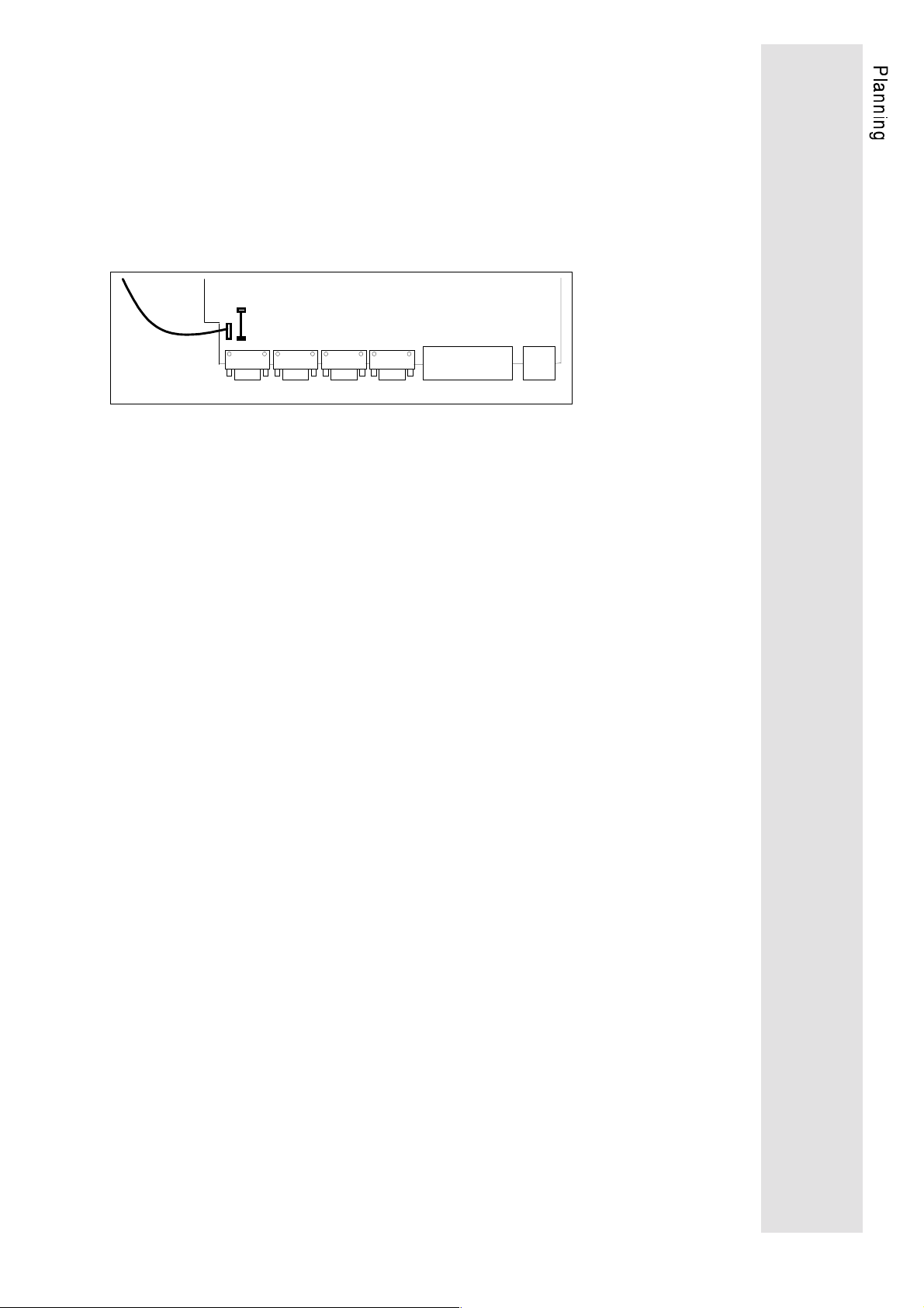
•
The axis modules should be installed at the same height at the righthand side of
the supply module:
−
If the axis modules have different power outputs, the more
powerful axis module must be placed directly next to the
supply module.
•
The interface connectors X1 to X4 and other terminals must be
covered with the supplied dust protectors or unused connectors
when not used.
10
Page 13
3.2. Electrical installation
•
The breakaway torque for the power terminals is 2.3 Nm
(20 lb in). Marking of terminals:
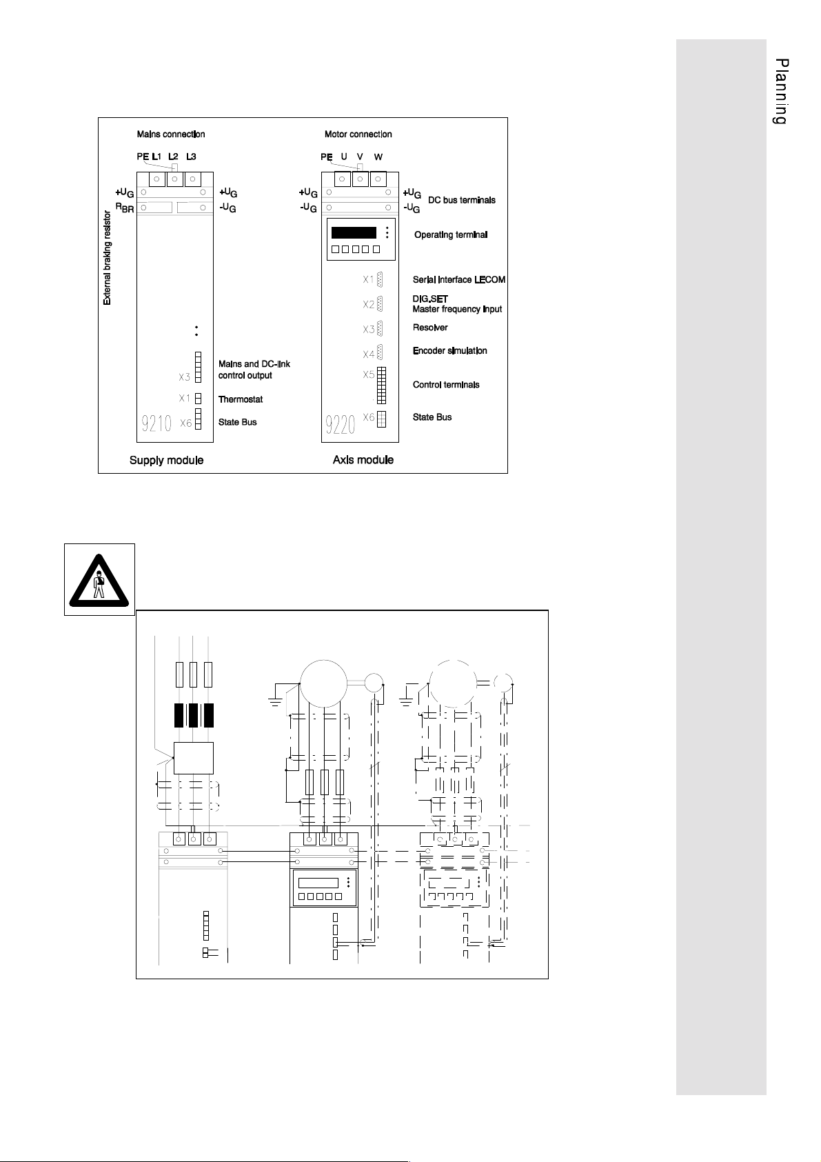
at 921X: +U
at 922X: +U
Supply modules
•
Without additional protective measures (e.g. zeroing) the units
may not be connected to a mains with e.l.c.b. (VDE
0160/05.88). In the event of an earth fault, a DC component in
the fault current can prevent the release of the e.l.c.b.
•
Operate the supply module with assigned mains choke.
•
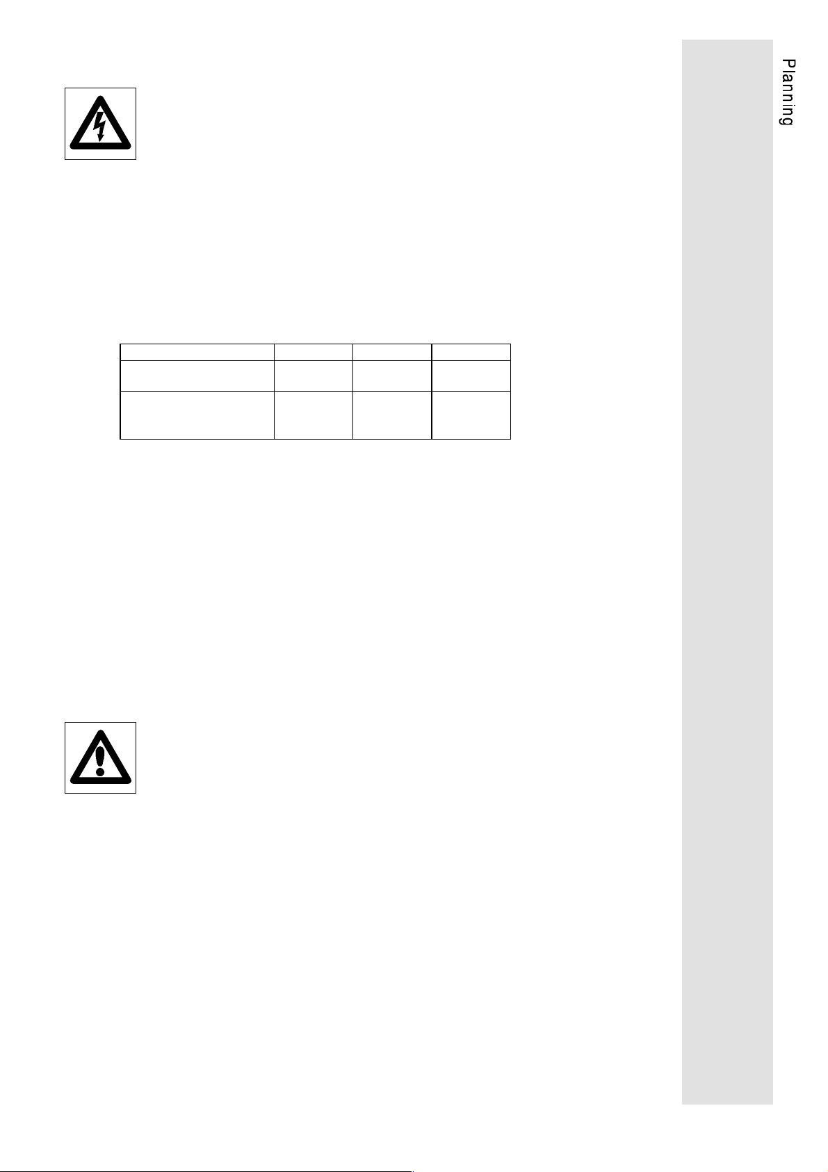
Power input
Recommended cable diameter and number of cores
Supply module 9212 9215 9217
Number of cores
Cable diameter [mm²]
or
AWG
Protect input cables according to their diameter with adapted
cable protection fuses.
•
Protection of the input rectifier:
−
Total protection with external very quick acting fuses in the
mains input (see chapter "Accessories")
−
If total protection is not required:
The normal cable protection fuses or miniature circuit
breakers which are adapted to the cable diameter offer
sufficient protection.
•
The peak power of the supply module must be equal to or
higher than the total peak power of the connected axis modules
and the rated power of the suply module must also be equal to
or higher than the total permanent power of the axis module
(see chap. 3.2.1).
, -UG, RBr, L1, L2, L3
G
, -UG, U, V, W
G
4
(L1,L2,L3,PE)4(L1,L2,L3,PE)4(L1,L2,L3,PE)
1,5 4 10
14/15 10/11 6/7
Note
The supply modules 921x hardware version E.4x onwards described in these
Operating Instructions may only be used in combination with the axis modules of
the hardware version E.4x and higher.
Axis modules
•
Connect only one motor to each axis module.
•
The cable diameter of the motor cables must correspond to the
rated current of the motor.
Protection by means of:
−
cable protection fuses or
−
adapted motor protection relay
•
Ensure motor protection:
−
use motor protection relay and monitor the thermostat of the
motor.
•
The connected motor may not be operated when the controller
is enabled, except for safety shutdown.
11
Page 14
3.2.1. Combination of several axis modules with one supply module
µ
Please note the following conditions when combining several axis
modules with one supply module:
•
The State-bus (X6) can supply max. 10 axis modules.
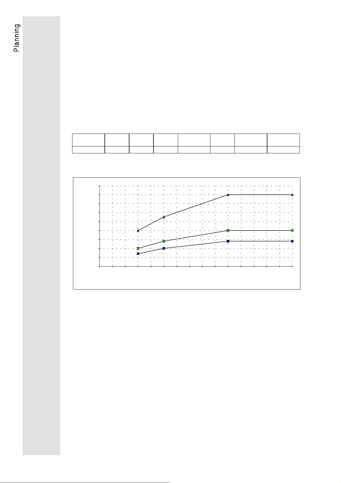
•
The sum of the total capacity of the DC-bus may not exceed a
certain value (see chart):
The permissible total capacity depends on the interval between
two closing operations and the mains voltage. The total capacity
is the sum of the capicities of the supply module and the axis
modules.
−
For intervals between two closing operations longer than
15 min, the max. permissible capacities are applied.
DC-bus capacities of the 9200 series
Type 9212 9215 9217 9222
9223
F]
C
ZK
[
235 705 1175 235 340 1100 2200
9224 9225
9226
Permissible total capacity depending on the interval between two closing
operations and the mains voltage
9000
8000
7000
6000
5000
4000
C (total) / µF
3000
2000
1000
0
0 1 2 3 4 5 6 7 8 9 101112131415
Switch-on distance / min
9215; 9217
V mains=400V-480V
9212
V mains=400V
9212
V mains=480V
9227
9228
12
Page 15

•
When selecting the power of the supply module, proceed as
follows to find out about the required input power.
1. Determine the power profile of all axis modules connected to
the DC-bus by means of the process profile and the load
torques during a system cycle.
2. The power losses are stated in the technical data, for units
the losses are stated during rated power and for motors the
power loss during rated operation. These losses are
assumed to be constant during the whole cycle.
3. Find out the resultant powr by adding the power losses and
the power profiles:
calculate a positive motor power
and a negative generator power.
4. Determin e the effective power during the system cycle:
Do not calculate a negative resultant power (generator
power). These ranges can taken into consideration when
calculating the effective brake power.
5. Select the supply module according to the effective power
during a system cycle:
Please note that the supply module must have enough
capacity to supply the effective peak power and that, in the
event of mains voltage reductions, the permissible power of
the supply module will be reduced according to the reduction
of the mains voltage.
6. If the calculated effective permanent power exceeds the
permissible value of the supply module 9217:
Subdivide the DC-bus sets and install further supply
modules.
13
Page 16

3.2.2. Screening and earthing
In order to avoid radio interference, care must be taken with the design and
connection of digital drives to avoid EMC disturbances during operation.
Digital drives are not more vulnerable to interference than analog drives, but the
effect is generally different. Interference of analog devices becomes obvious as
irregularities in speed. Interference of digital drives may cause
program errors; therefore it is important that the drives are inhibited
immediately when interference occurs. This is done by setting the
TRIP function (CCr).
In order to avoid these problems, care must be taken with ground
(GND), protective earth (PE) connections as well as screening.
•
Screen control cables and motor cables.
•
Ensure effective screening:
−
a non-earthed conductior should be used to maintain screen
integrity where cahbles are interrupted (terminal strips,
relays, fuses).
Caution!
To increase the EMC (electromagnetic compatibility), the reference GND is
connected to the protective earth (PE) inside the drive.
Fehler! Es
ist nicht
möglich,
durch die
To ensure an optimum interference suppression, the screening and the GND-PEconnection is made differently for single drive and multi drive
networks.
Single drive
•
Connect the screen of the control cables to PE of the drive at
one end to avoid earth loops.
•
GND and PE are connected by a jumper inside the drive.
•
In case of firmly installed computer connections, a mains
isolation (e.g. Lenze Converter 2101) is mandantory between
computer and axis module.
•
The screens of the motor cables
−
should be as large as possible.
−
connected to the two sides.
14
Page 17
Multi drive networking
•
When laying the ground cables, care must be taken that there
are no ground loops. To ensure this, the GND-PE connection
must be removed in every drive. For the 9200 drives, turn the
four screws on the cover one haft turn CCW and pull out the
control board. Remove the jumper PE-BR on the board 9220
MP. CAUTION: Ensure that the mains has been disconnected
and the drive has been switched off at least 5 minutes before
removing any parts.
cable
PE
BR-PE
Control board 9220MP
X1 X2 X3 X4
SubD-plugs
•
All ground cables must then be lead to external, insulated
X5
Control terminals
central points, centralized again from there and connected to
PE in the central supply. The PE-GND reference is necessary
as the electronics insulation (SubD plug) does not allow
voltages >50V~ AC at PE.
•
In case of firmly installed computer connections, a mains
isolation (e.g. Lenze Converter 2101) is mandatory between
computer and axis module.
•
The individual cable screens must be connected to external
insulated centreal points, which are then connected to the PE
potential at one point.
•
The screens of the motor cables
−
should be as large as possible.
−
should be connected to the two sides.
X6
15
Page 18

3.2.3. Radio interference suppression
According to § 13 and § 14 of the legislation of the European
Community relating to the electromagnetic compatibility of devices
(EMVG v. 09.11.92) the national standards and regulations are only
interim standards vilid until December 31, 1995. In addition, the
harmonized European standards can be fulfilled following the
recommendations below. Measures against radio interference
suppression depend on the site of the device to be installed:
Previous national standards
The application without radio interference suppression in electrical
systems within connected working areas or industrial premises can
only be allowed if, outside the industrial premises, the limit values
according to VDE 0871/6.78, class B are not exceeded (General
allowance according to the standard on the operation of highfrequency devices of December 14, 1984, official no. 1045/1046).
For operation within residential areas or when exceeding the limit
value class B outside of industrial premises, radio interference
suppression according to VDE 0871, limit value class B is required.
Future hormonized standards
The standard prEN 50081-2 is valid for the radio interference
suppression.
It refers to standard EN 55011 (VDE 0875, part 11, limit value class
A and B).
•
Within industrial premises, which are not connected to the public
low-voltage supply, the limit values to EN 55011, limit value
class A apply.
•
Within residential areas or industrial premises, which are
connected to the plublic low-voltage supply, the limit values to
EN 55011, limit value class B apply.
Radio interference suppression to EN 55011, limit value class
A or B, can be achieved by:
•
Using a suitable mains filter and screening of motor cables,
brake resistor cables and the power cable between mains filter
and inverter (for recommended mains filters see "Accessories").
16
Page 19
4. Drive connections
4.1. Power connections
4.1.1. Mains and motor connection
Caution!
All power terminals carry mains potential up to 5 minutes
after mains disconnection.
The DC-bus terminals +UG -UG and the PE terminals of the supply
and axis module must be connected by means of busbars
(accessory kit).
17
Page 20
4.1.2. External brake resistor
To increase the permanent brake power, an external brake resistor
with a higher permanent power can be installed instead of the
internal resistor. In this case, the internal brake resistor must be
disconnected.
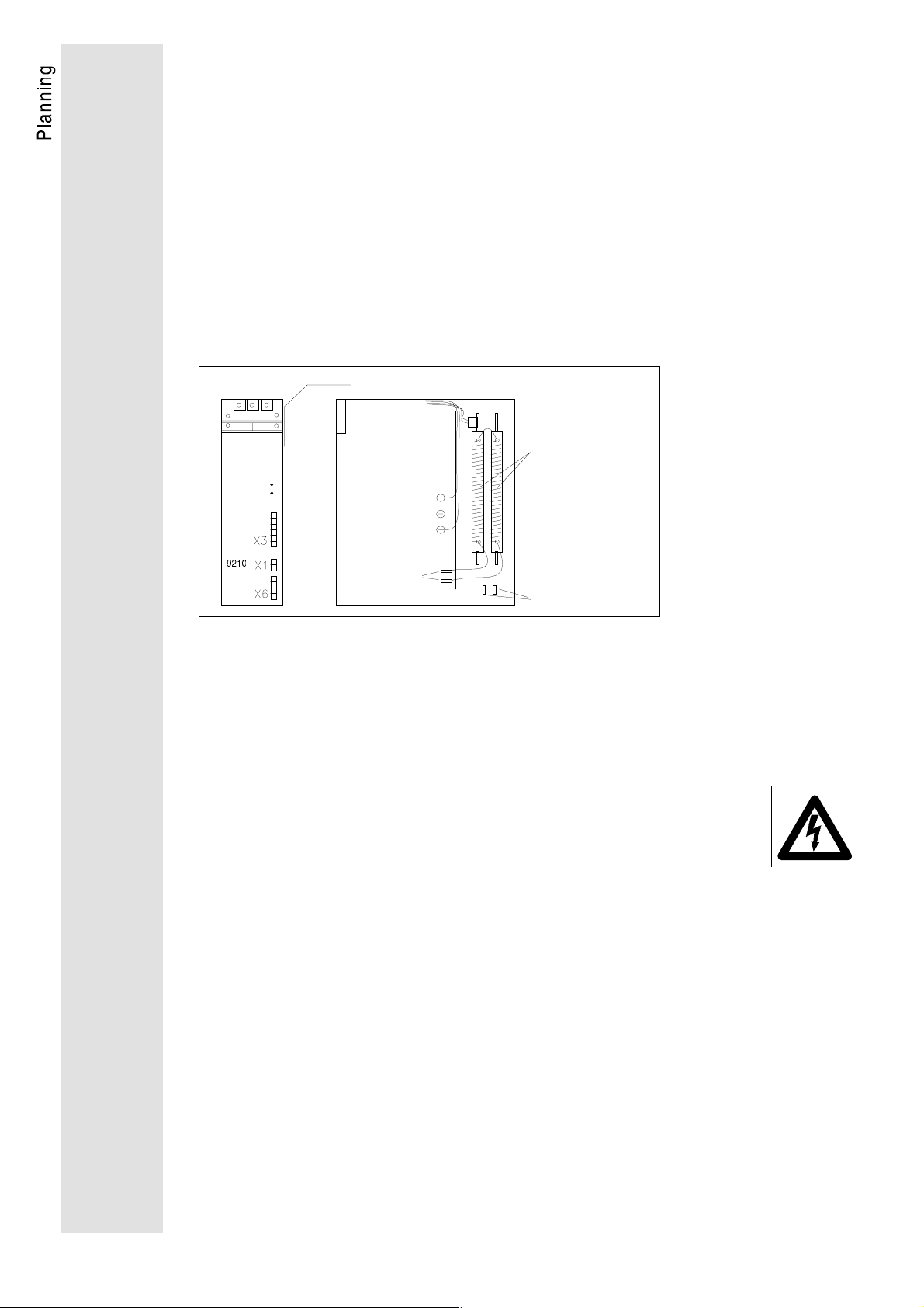
Disconnection of the internal resistor:
1. Remove right side of the supply module housing 9210, when
no voltage is applied.
2. Disconnect spade plug.
3. Connect spade plugs to tabs on the housing.
4. Close housing again.
1.
4.
in t er nal
brake resistor
2.
3.
The external brake resistor must be connected to the power
connections +U
recommended to exclusively use resistors with integrated overload
protection which disconnect the mains supply in case of overload
(for recommended resistors see chapter "Accessories"). The
surface temperature of the resistor may reach 360°C.
Caution!
When using brake resistors without overload protection, the resistors may burn due
to a fault (e.g. mains overvoltages >528V, application specific overload or internal
faults).
and RBR at the supply modules 9210. It is
G
18
Page 21
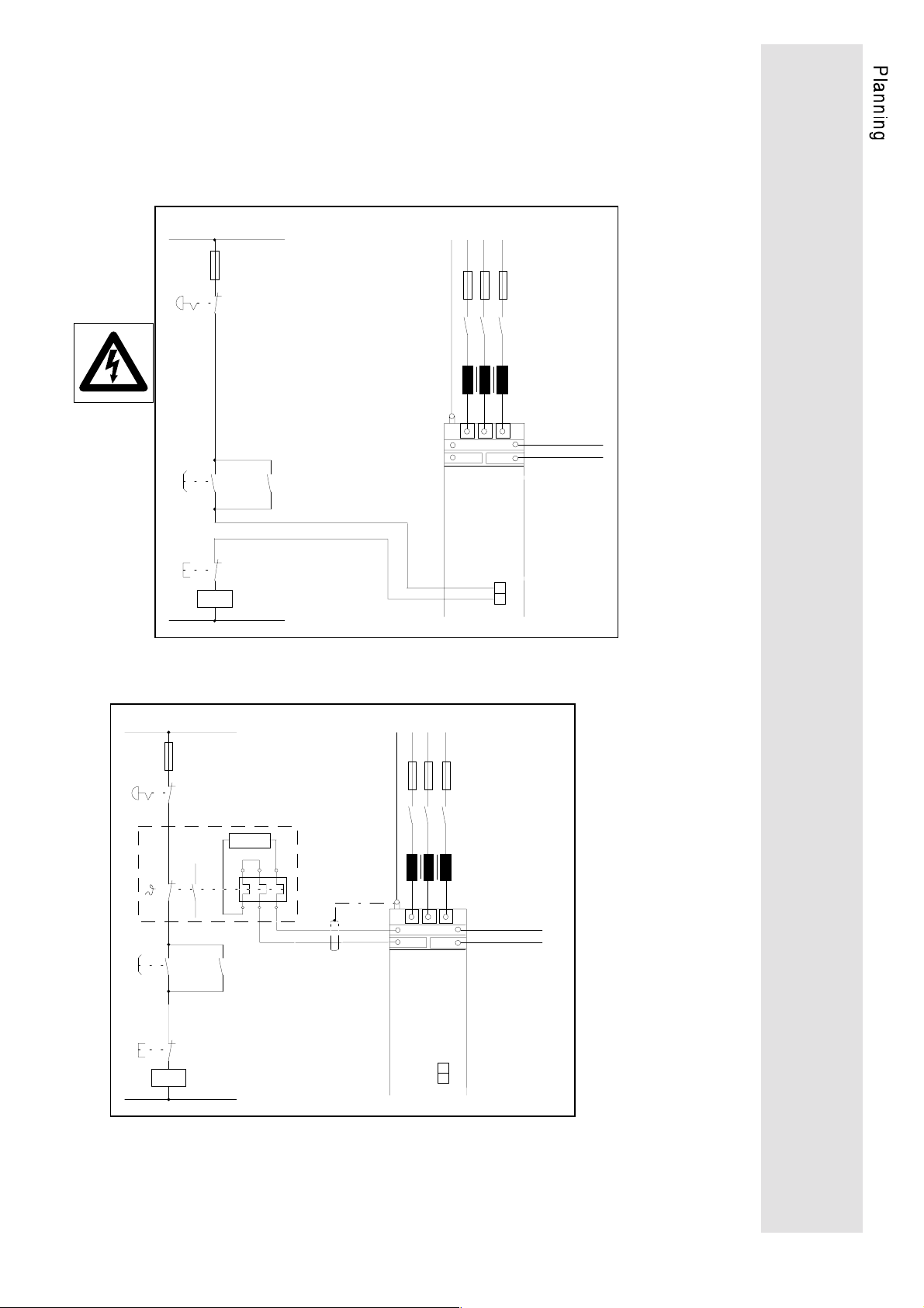
Wiring of brake resistor
Caution
K1 must additionally set controller enable!
Wiring when using the internal brake resistor
Wiring when using the external brake resistor
19
Page 22

4.2. Control connections of supply module
4.2.1. Overheat of internal brake resistor (9210 X1)
The thermal contact (capacity 230V/10A) of the internal brake
resistor can be accessed via the connector X1 of the supply
module. It can be used to switch off the mains in case of overload
of the internal brake resistor (see also: External brake resistor).
Caution!
Unlike previous models of this series, the connector X1 of the supply module does
not have to be bridged any more. This connector cannot be used for the monitoring
of an external thermal contact and the like! To protect the inverter, wiring according
to figure "Wiring using the internal brake resistor" (page 19) is necessary.
4.2.2. Mains and DC-bus monitoring (9210 X3)
At X3 of the power supply module several signals are available,
that give information about the status of the mains. The wiring of
this terminal is not necessary to make the device work. If the
software feature mains failure with DC-bus controlling is required,
the terminals X3,1 and X3,3 must be wired. By using an external 24
V supply there is an optoisolated signal of mains failure at terminal
X3,5.
For further information see: Parameter setting, page 50.
20
Page 23
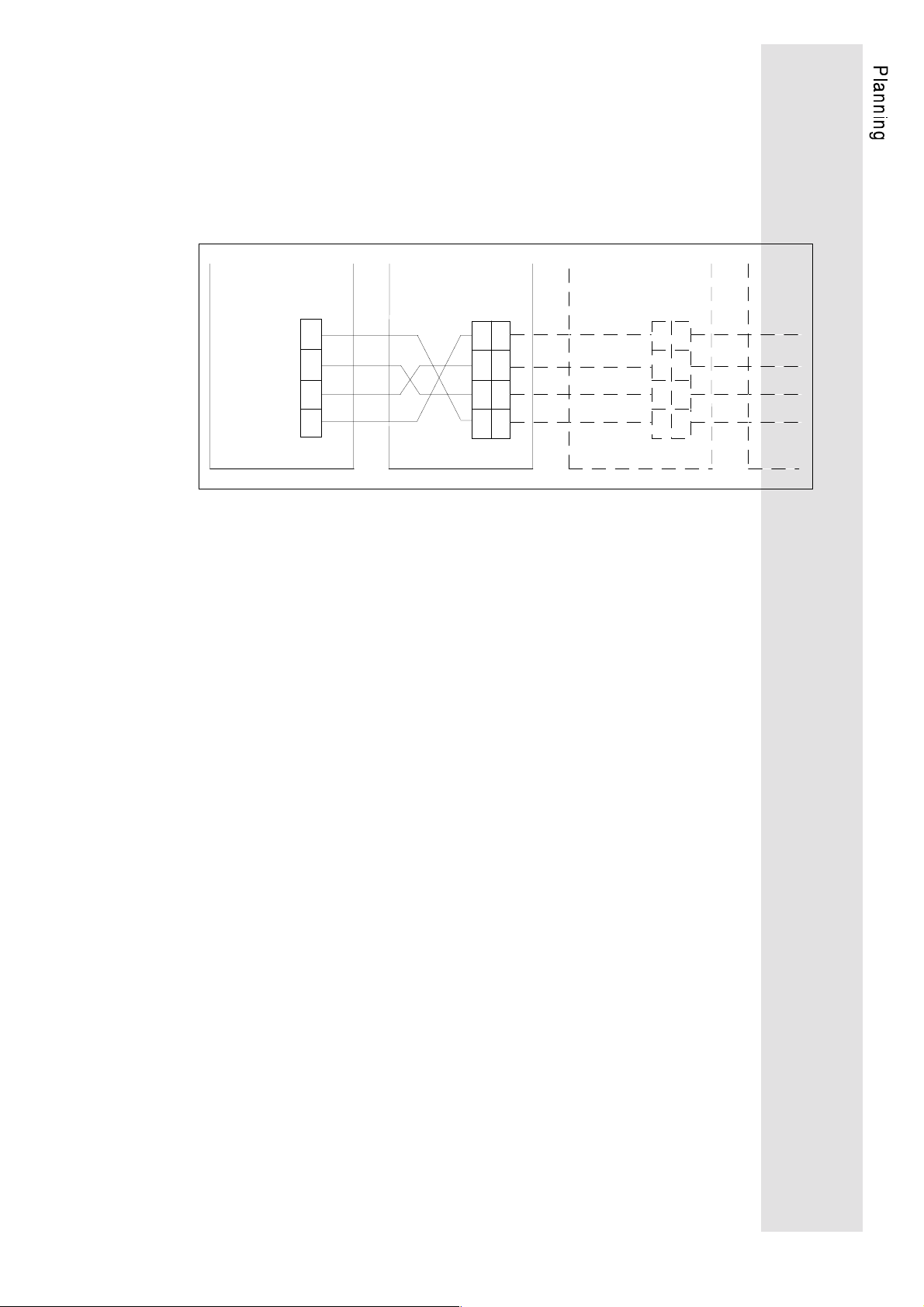
4.2.3. State bus
By means of the state bus X6, the supply module gives status
information like ready, overvoltage, and heat sink or resistor
overtemperature to the connected axis modules. The four state bus
cables must be taken from the supply module to the axis modules.
The terminals in the axis module which are next to each other are
internally bridged.
9210
State Bus
X6 X6 X6
9220 9220
State Bus State Bus
GND
Temp
RDY
Umax
When the modules are ready to operate, the following levels are
applied at the terminal of the state bus:
•
Temp -> GND : approx. 0...2 V
•
RDY -> GND : approx. 0...2 V
•
V
GND : more than 2 V
max
These levels can only be measured when the state bus is
connected between the supply module and the axis modules.
Umax
RDY
Temp
GND
Umax
RDY
Temp
GND
21
Page 24
4.3. Control connections axis module
4.3.1. Control terminals
Pin assignment of the control terminal block X5
4.3.2. Analog input and outputs
Analog set value selection
For analog set value provision, two inputs are available, either as
speed or torque set value provision (for selection see C005
configuration). The bipolar input is a differential input..
a) bipolar set value selection b) unipolar set value selection
82kOhm
68kOhm
100kOhm
12
-
82kOhm
68kOhm
R304
100kOhm
X5 X5
Master voltage
-10...+10V
44kOhm
44kOhm
R306
9
8
7
S
A
-
Set value
potentio-
E
meter
10 kOhm/lin.
Master voltage
0...+10V
Monitor outputs
The terminals 62 and 63 of the control terminals block X5 transform
internal digital control signals into analog output signals. The
resolution is 8 bit. The signals are updated every 2ms. The
maximum monitor output current capacity is 2mA.
22
Output Terminal Signal Range Level
Monitor 1
Monitor 2
X 5 62 Actual s peed v alue adjustable via C153/C154 -10V...+10V
X 5 63 Torque set value -M
max
...+M
max
-10V...+10V
Page 25
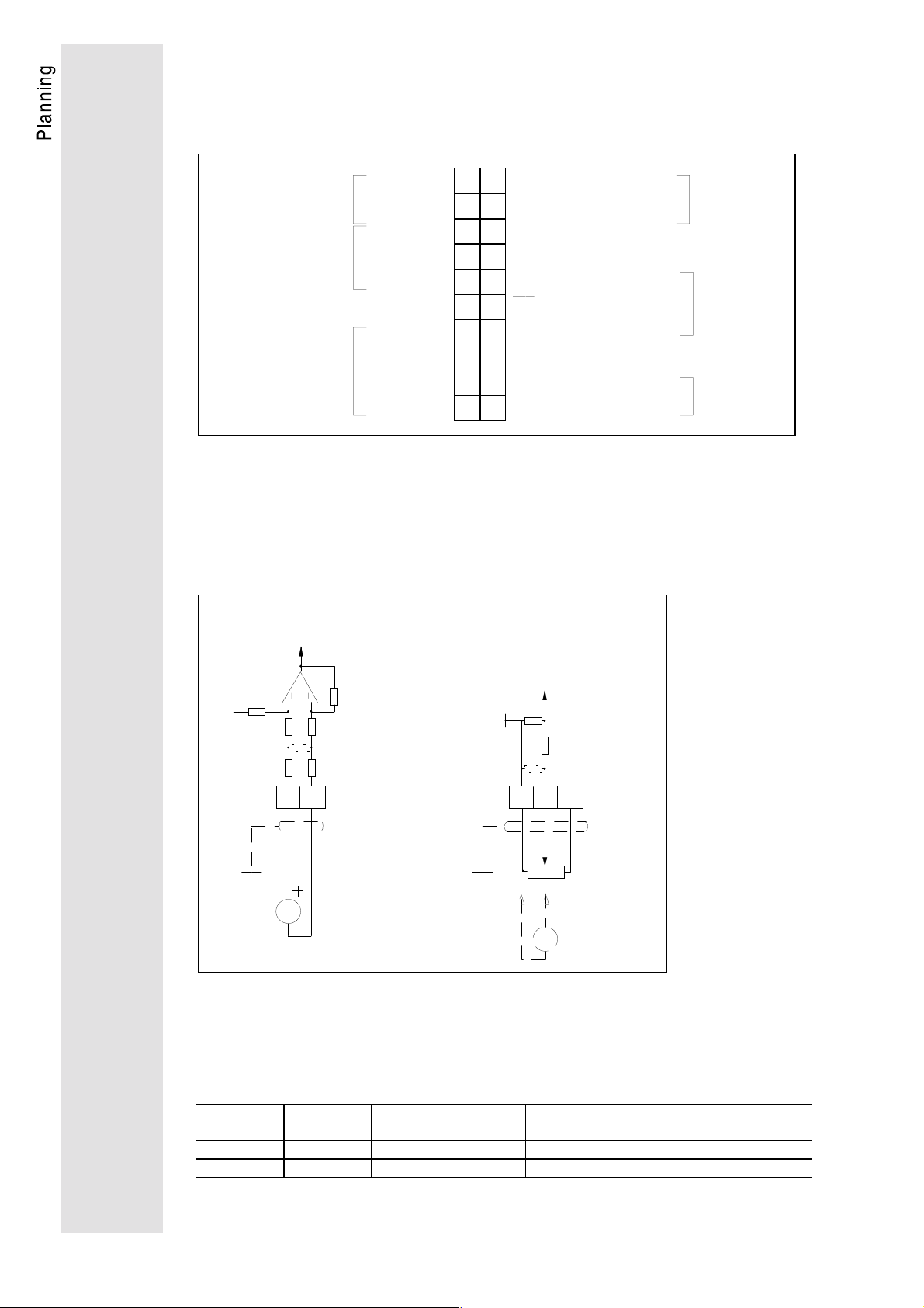
4.3.3. Digital inputs and outputs
External 24 V supply Internal 15 V supply
Caution!
GND is internally connected to PE
via jumper BR-PE.
+Vcc
20 21 22 24 26 27 28 39 40 41 42 44 59
2k2
2k2
R
2k2
2k2
TRIP SET
JOG
L
2k2
2k2
TRIP RESET
RFR
GND
-
56R
56R
TRIP
Qmin
56R
RDY
c
X5
Caution!
Bridge signals X5,39 and X5,40.
+Vcc
2k2
2k2
20 21 22 24 26 27 28 39 40 41 42 44 59
R
2k2
2k2
TRIP SET
JOG
L
2k2
2k2
TRIP RESET
RFR
GND
TRIP
56R
56R
Qmin
56R
X5
RDY
d
QSP
+
Legend
Marking Function at signal = HIGH
Digital outputs
I 7 50mA
Digital inputs
(active at 13 ... 30 V) TRIP RESET Fault reset
I 7 10mA
Relay
RDY Ready
Qmin
Motor speed > value of C017 (fact ory Setting)
The function depends on C117
TRIP
No faults
RFR Controller enable
TRIP SET
No fault switch-off (Motor thermostat)
JOG Internal set value
QSP No quick stop with this switch position
c
d
Relay 24 V, R
Relay 15 V, R
QSP
1 kΩ, e.g. order no. EK00326005
≥
i
600 Ω, e.g. order no. EK00326850
≥
i
23
Page 26
Comment on QSP function
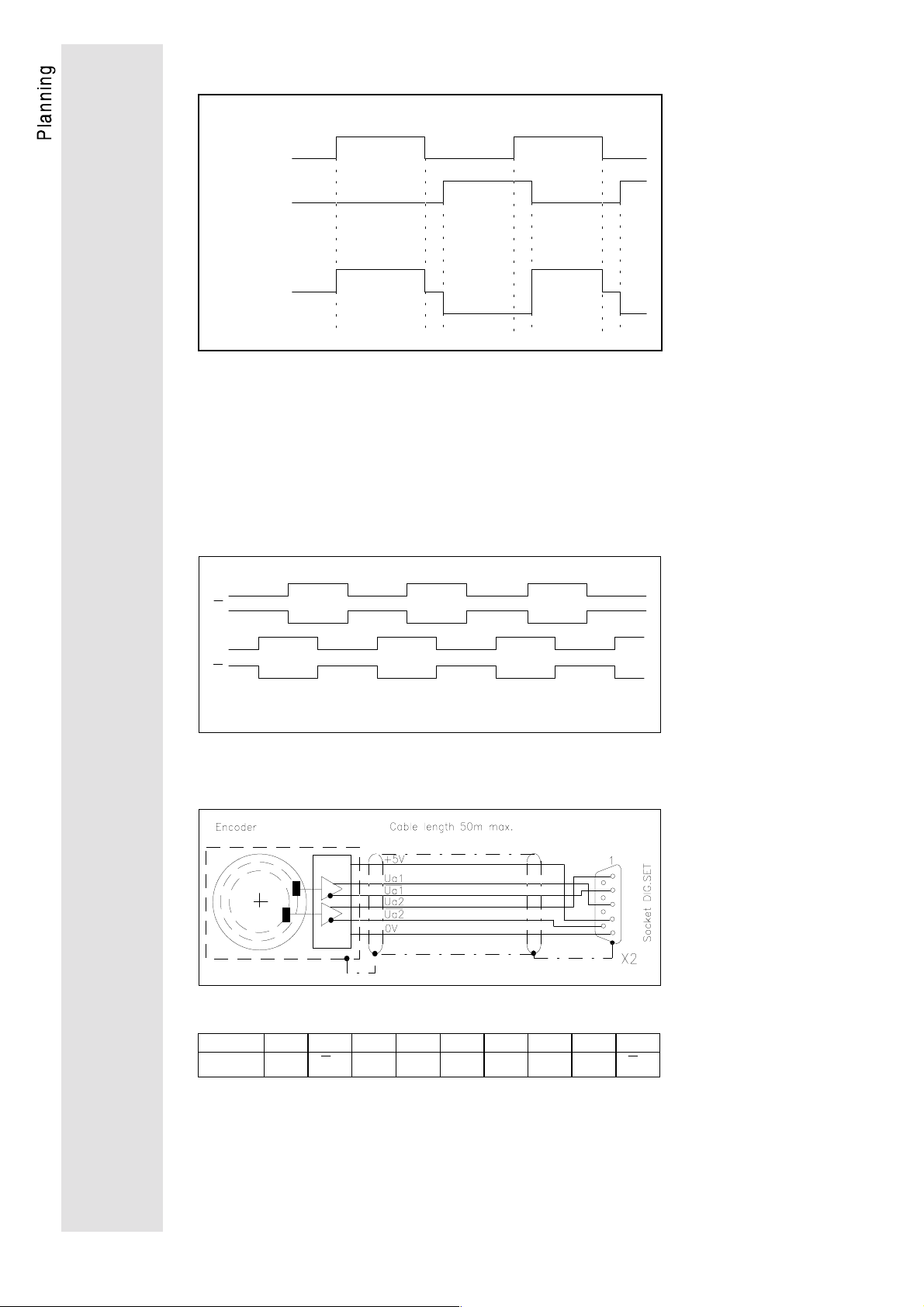
Master frequency selection
For speed set value selection by means of a master frequency, the
9-pole SubD Dig.Set (X2) is used. As master frequency signal
either the simulated encoder signal of the master drive or an
incremental signal source with two TTL complementary signals
shifted by 90° el. can be used. The zero track of the master
endcoder will not be evaluated. The maximum input frequency is
300 kHz. The current consumption per channel is 6 mA.l.
A
A
B
B
T T L /0 ...3 0 0 k Hz
a) Master frequency input by incremental encoder
Pin assignment X2 male plug Dig.Set
24
Pin 123456789
Signal
U
a2
U
U
a1
+ 5V GND -- -- --
a1
U
a2
Page 27
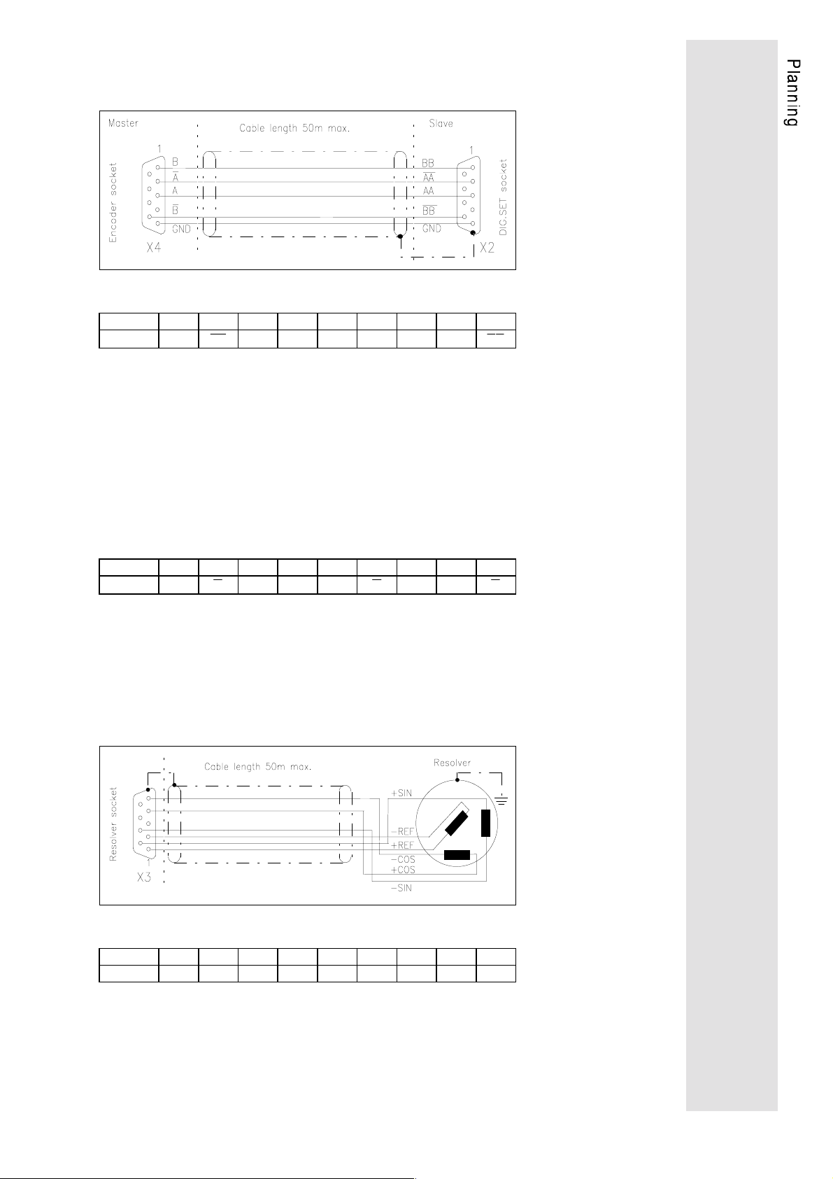
b) Master frequency input by encoder output signal of the
master drive
Pin assignment X2 male Dig.Set
Pin 123456789
Signal
BB
AA + 5V GND -- -- --
AA
BB
Encoder simulation
The encoder socket (X4) is used as an output for the encoder
simulation. Two TTL complementary signals (V
_ 2,5V, V
high
low
_
0,5V at I = 20mA) shifted by 90°C with 256, 512, 1024 or 2048
increments are generated per revolution (adjustable via C030). This
output is used for actual value feedback for closed-loop control
(positioning control) or as a set value for slaves (master/slave
operation). The current capacity is 20 mA per channel.
Pin assignment X4 encoder socket
Pin 123456789
Signal
B
A+ 5VGND
A
Z
ZLC
B
Resolver
2-pole resolvers (V=10V,f=5kHz) are fitted as standard. The Lenze
servo motors are already equiped with the corresponding resolvers.
The resolver is connected by means of a 9-pole socket (X3). The
resolver supply cable and the resolver are monitored for open
circuit (fault indication Sd2).
Pin assignment X3 resolver female plug
Pin 123456789
Signal
+REF -REF GND +COS−COS +SIN−SIN -- --
25
Page 28

5. Application examples
5.1. Variant with integrated positioning module 2211PP
Easy positioning tasks can be solved by applying the positioning
module 2211PP. Thus, you sometimes do not need a PLC or at
least reduce the load of the PLC. The positioning module can be
integrated into the unit and adapted to several applications.
Different designs are available, e.g. the basic module with or
without a terminal extension and alternatively a field bus module as
Interbus-S.
Lenze
Servo 9200
26
Page 29

Features of the positioning module 2211PP:
•
32 freely assignable digital inputs with 8 or 28 via terminals
according to variant
•
32 freely assignable digital outputs with 4 or 16 via terminals
according to variant
•
Absolute or relative measuring system
•
32 program sets, each with the following functions:
point to point positioning
point to point positioning with velocity profile
positioning to an interrup-input
acceleration, deceleration, traversing and final speed adjustable
waiting for input
switching of several outputs
homing according to 6 different modes
adjustable waiting time
adjustable number of pieces for repeat function
program branching depending on inputs
jump to following program set
•
32 adjustable positions
•
32 adjustable speeds
•
32 adjustable acceleration and deceleration values
•
32 adjustable number of pieces
•
32 waiting time
•
Manual and program operation
•
Input and display via the operating unit of the 9200 basic unit
•
Parameter setting and programming via the serial interface
LECOM A/B of the basic unit by means of the PC program
Lemoc2 (via menu)
•
Connection of a BCD switch possible
•
Connection of an absolute encoder possible
•
Control, parameter setting, and programming via Interbus-S or
Profibus possible
•
The function Winding calculator is available as alternative
system software on the same hardware basis as the positioning
module.
Note:
Please additionally note the Operating Instructions of the
positioning system.
27
Page 30

5.2. Wiring with positioning control SX-1
5.2.1. Diagram 1: Mains supply
28
Page 31

5.2.2. Diagram 2: Control circuit 230V
29
Page 32

5.2.3. Diagram 3: Control circuit 24V
30
Page 33

5.2.4. Diagram 4: Control connections 9200 - SX1
Ω
31
Page 34

5.2.5. Diagram 5: Control connections SX1
32
Page 35

6. Accessories
(All listed components must be ordered separately)
6.1. External brake resistors
9212
9215
9217
R
[Ω]Pn[kW]
29 1,1 ERBD029R01k1 120 430 510 92 64
11 1,1 ERBD011R01k1 120 430 510 92 64
8,5 1,1 ERBD009R01k1 120 430 510 95 64
Order no. H
6.2. Mains chokes
[mm]M[mm]O[mm]R[mm]U[mm]
[mH]I[A]
9212
9215
9217
3 x 2,5 3 x 7 ELN3_0250H007 120 61 84 45 130 105 73 6.0 11
3 x 1,2 3 x 25 E LN3_0120H025 150 76 140 61 180 140 95 5.0 10
3 x0,75 3 x 45 ELN3_0075H045 180 91 161 74 225 165 120 6.3 11
L
Part no. a
[mm]b[mm]c[mm]d[mm]e[mm]f[mm]k[mm]m[mm]n[mm]
33
Page 36

6.3. RFI filter
For radio interference suppression according to EN 55011, limit
value class A or B.
Assigned RFI filters for mains voltage of 400 V
Supply module type 9212 9215 9217
Mains current RFI filter
Order no. mains filter
8 A 25 A 50 A
EZF3_008A001 EZF3_025A001 EZF3_050A004
Filter for mains voltages of up to 460 V: please contact
manufacturer
6.4. External fuses
Semiconductor protection
External fast acting fuses in the mains input protect the input
rectifier in the supply module.
Recommended semiconductor protection fuses (at mains side):
Supply module 9212 9215 9217
Mains input with
rectifier protection
Order no.
FF
20A / 700V
14 x 51
EFSFF0200ARH EFSFF0630ARI EFSFF1000ARI
FF
63A / 700V
22 x 58
FF
100A / 700V
22 x 58
Input cables must be protected with standard fuses adapted to the
cross-sectional area of the cables.
6.5. System cables
Note
For best interference immunity results, cut the cables to the required length.
6.5.1. System cables for control terminal block X5
Fehler! Es
ist nicht
möglich,
durch die
34
Design for left X5 terminals right X5 terminals
Order no.
EW00340899 EW00340898
Page 37

6.5.2. System cables for master frequency selection X2 and
incremental encoder output X4
green
black
black
red
black
yellow
black
white
P o s itio n in g c o n t ro lle r A x is m o d u le A x is m o du le m a st e r A x is mod ule s la v e
Design with plugs at both ends with single plug
Order no.
Fehler! Es
ist nicht
möglich,
Note:
The bridge beween pin 4 and pin 8 is necessary for the
operation with the SX1 positioning control.
EW00340900 EW00340906
durch die
35
Page 38
6.5.3. System cables for resolver X3
Various lengths
+REF white
- REF black
- SIN black
+SIN yellow
-COS black
+COS red
Order numbers of resolver cables
Length plugs at both ends plug at motor side plug at unit side
2.5 m
5 m
10 m
15 m
20 m
25 m
30 m
35 m
40 m
45 m
50 m
- - EW00340907
EWREB_______05 EW00345891 EWREB_______10 EW00340909 EWREB_______15 EW00345892 EWREB_______20 EW00345893 EWREB_______25 EW00345894 EWREB_______30 EW00345895 EWREB_______35 EW00345896 EWREB_______40 EW00345897 EWREB_______45 EW00345898 EWREB_______50 EW00345899 -
36
Page 39

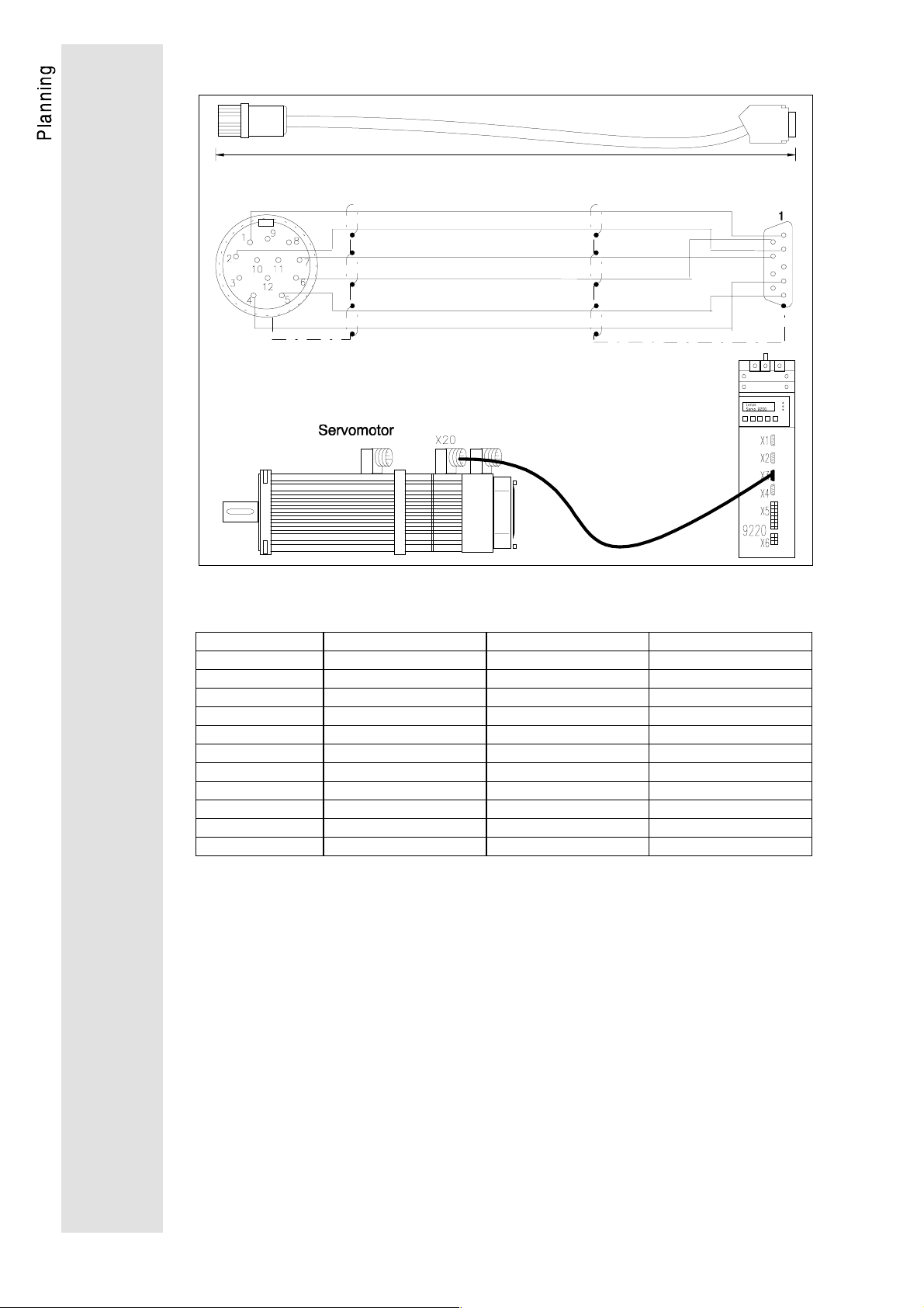
6.5.4. System cables for power supply of servo motors
Various lengths
white
brown
1
5
6
4
2
black 1
black 2
black 3
blank
12 456 PE
X11
U
V
W
0.5 mm
1.5 mm
or
2.5 mm
UVW
M
3
2
2
2
Order numbers of motor cables
Length 4 x 1.5 mm
2 x 0.5 mm
5 m
10 m
15 m
20 m
25 m
30 m
35 m
40 m
45 m
50 m
EWMOL056_01505 EWMOL056_02505 EWMOL100_04005 EWMOL112_10005
EWMOL056_01510 EWMOL056_02510 EWMOL100_04010 EWMOL112_10010
EWMOL056_01515 EWMOL056_02515 EWMOL100_04015 EWMOL112_10015
EWMOL056_01520 EWMOL056_02520 EWMOL100_04020 EWMOL112_10020
EWMOL056_01525 EWMOL056_02525 EWMOL100_04025 EWMOL112_10025
EWMOL056_01530 EWMOL056_02530 EWMOL100_04030 EWMOL112_10030
EWMOL056_01535 EWMOL056_02535 EWMOL100_04035 EWMOL112_10035
EWMOL056_01540 EWMOL056_02540 EWMOL100_04040 EWMOL112_10040
EWMOL056_01545 EWMOL056_02545 EWMOL100_04045 EWMOL112_10045
EWMOL056_01550 EWMOL056_02550 EWMOL100_04050 EWMOL112_10050
2
2
4 x 2.5 mm
2 x 0.5 mm
Cable cross section
2
2
4 x 4.0 mm
2 x 0.5 mm
2
2
4 x 10 mm
2 x 0.5 mm
2
2
37
Page 40

6.5.5. System calbes for supply fo fan and brake
Various length
black 1
black 2
brown
blue
green-yellow
X30X30
Servo motor
Dotted line: m otor with brake but without fan: DSV A BS X X
L1 fan
N fan
Y1 + brake
Y2 - brake
PE
Y1+ Y2- L1 N PE
Order numbers of fan and brake supply cables
Cable cross section
Length 5 x 0.5 mm
5 m
10 m
15 m
20 m
25 m
30 m
35 m
40 m
45 m
50 m
EWBLL_______05
EWBLL_______10
EWBLL_______15
EWBLL_______20
EWBLL_______25
EWBLL_______30
EWBLL_______35
EWBLL_______40
EWBLL_______45
EWBLL_______50
2
0.5 mm
2
38
Page 41

6.6. Motors
Asynchronous servo motors DSV/DFV series
Motor type Technical data of motors Standstill
brake
Vn = 205 V
DSVARS 56
DSVABS 56
DSVARS 71
DSVABS 71
DFVARS 71
DFVABS 71
DSVARS 80
DSVABS 80
DFVARS 80
DFVABS 80
DSVARS 90
DSVABS 90
DFVARS 90
DFVABS 90
DSVARS 100
DSVABS 100
DFVARS 100
DFVABS 100
DSVARS 112
DSVABS 112
DFVARS 112
DFVABS 112
n
M
2.0
2.0
4.0
4.0
6.3
6.3
5.4
5.4
10.8
10.8
9.5
9.5
19.0
19.0
12.0
12.0
36.0
36.0
17.0
17.0
55.0
55.0
n
PnV
0.8
0.8
1.7
1.7
2.2
2.2
2.3
2.3
3.9
3.9
4.1
4.1
6.9
6.9
5.2
5.2
13.2
13.2
7.4
7.4
20.3
20.3
n3~In
390
390
390
390
390
390
390
390
390
390
350
350
390
390
330
330
390
390
320
320
390
390
n
1
-
[min
] [Nm] [kW] [V] [A] [Hz] [kgcm2] [kg] [Nm] [A] [A]
3950
3950
4050
4050
3410
3410
4100
4100
3455
3455
4110
4110
3480
3480
4150
4150
3510
3510
4160
4160
3520
3520
2.4
2.4
4.4
4.4
6.0
6.0
5.8
5.8
9.1
9.1
10.2
10.2
15.8
15.8
14.0
14.0
28.7
28.7
19.8
19.8
42.5
42.5
fncos
140
140
140
140
120
120
140
140
120
120
140
140
120
120
140
140
120
120
140
140
120
120
0.70
0.70
0.76
0.76
0.75
0.75
0.75
0.75
0.80
0.80
0.80
0.80
0.80
0.80
0.78
0.78
0.80
0.80
0.80
0.80
0.80
0.80
ϕ
JmMnI
2.6
3.0
5.8
6.8
5.8
6.8
19.2
23.0
19.2
23.0
36.0
40.0
36.0
40.0
72.0
81.5
72.0
81.5
180.0
212.0
180.0
212.0
6.4
6.9--2.5--0.06----
10.4
11.2
12.0
12.9
15.1
16.9
16.9
18.7
22.9
25.0
25.5
27.1
44.7
47.4
48.2
50.9
60.0
66.5
63.5
70.0
--
11.0
--
11.0
--
12.0
--
12.0
--
22.0
--
22.0
--
40.0
--
40.0
--
80.0
--
80.0
=
0.08
0.08
0.09
0.09
0.09
0.09
0.11
0.11
0.18
0.18
Fan
230V
∼
50/60Hz
I
n
n
--
--
--
--
0.12
0.12
--
--
--
--
0.12
0.12
--
--
--
--
0.25
0.25
--
--
--
--
0.25
0.25
--
--
--
--
0.24
0.24
For further information about servo motors please see the
operating Instuctions "Three-phase servo motors".
39
Page 42

Parameter setting
1. LCD display
Ready (green)
Curr. limit I
max
Impulse inhibit
(ye llow )
(red)
SH
STPPRG
Keys
1.1. Key functions
Key Function
PRG Change between code and parameter level
▲
▲
+ SH
▼
▼
+ SH
SH + PRG Execute change. Reset after fault i ndi cation
STP Inhibit controller (see note below)
SH + STP Enable controller
Note
•
For the execution command SH+PRG and the enable command SH+STP first
press the SH key and hold, than press the PRG or STP key.
•
When inhibiting the controller by pressing the STP key, it must be enabled
again by using the SH+STP command. Only then can it be
enabled via terminal 28 or interface.
Increase displayed value
Rapid increase of displayed v al ue
Reduce displayed value
Rapid reduction of displayed v al ue
Fehler! Es
ist nicht
möglich,
durch die
40
1.2. Plain-text display
The LCD display constists of two lines of 16 characters each. In the
upper line, code no. and parameter are displayed. The arrow >
shows the present level (code or parameter level), which can be
changed when pressing the ▲ or ▼ key. In the lower line, the
codes or parameters are explained.
-Arrow for code level-
Code no.- -Parameter-
↓ -
>C001 - 0Operat i ng mode
-Explanatory text-
Page 43

2. Basics of parameter setting
The drive can be adapted to your specific applications by
parameter setting of the axis modules. The possible settings are
arranged in the form of codes, which are numbered in ascending
order and start with the letter "C". Each code provides several
parameters which can be selected according to the application.
Parameters can be direct values of a physical unit (e.g. 50Hz or
50% related to f
information (e.g. -0- = controller inhibited, -1- = controller enabled).
In cases where the parameters represent values of physical units, it
is possible to vary the increment.
Example: The acceleration and deceleration can be set in
increments of 0.01 s up to 1 s and in increments of 0.1 s from 1 s
upwards.
For codes with more than 5 digit values, the keypad operation is
different: In the parameter level, the cursor can be shifted to enter
large values. This is done by pressing SH+ ▲ and SH+▼ (see
example on page 44).
In some codes, parameters can only be read but not changed.
In the factory setting, only those codes are displayed which are
necessary for the most common applications. For activation of the
extended code set see code table C 000.
) or numerical codes giving certain status
dmax
2.1. Change parameters
Each code has a factory set parameter which can be changed.
There are three different ways of selecting and confirming a new
parameter, depending on the code:
Direct acceptance
The servo axis immediately accepts the new parameter, i.e. while
you change it using the ▲ or ▼-key. This is possible even when the
drive is running. Parameters which are immediately accepted are
marked with
Acceptance with SH + PRG
The axis accepts a new parameter when SH + PRG are pressed.
This is possible even with the drive running. First press SH and
then in addition PRG. The display shows --ok-- for 0.5 seconds.
The axis module now works with the new parameter. The key
combination SH and PRG can be compared to the "return" key on
your computer keyboard. If you have to set a parameter of a code
in this way, the code table shows the symbol
ON-LINE
in the code table.
SH + PRG
.
41
Page 44

Acceptance with SH + PRG with controller inhibit
The axis module accepts the new parameter when it has been
inhibited prior to pressing SH + PRG. Inhibit the controller e.g. by
pressing STP. First press SH and then in addition PRG. The
display shows --ok-- for 0.5 seconds. The axis module works with
the new parameter when the controller is released again. If you
have to set a parameter of a code in this way, the symbol
appears in the code table.
2.2. Save parameters
•
When commissioning for the first time, the parameter set 1 is
factory-set. After the acceptance, new parameters are saved in
the RAM, i.e. they are saved until the controller is disconnected
from the mains.
If you do not want to lose your setting when connecting the
controller to the mains, save them permanently:
1. Select code C003.
2. Select parameter set 1 by entering -1- .
3. Press SH first, and then additionally PRG. --ok-- will be
displayed.
4. Now you can disconnect the servo controller from the mains.
Your settings are permanently saved under "parameter set
1".
•
Password
The input of a password prevents unauthorized changes of
parameters or code levels.
2.3. Load parameter
If you only need one parameter set, you can permanently save
your changes under parameter set 1. After every mains connection,
parameter set 1 is loaded automatically.
42
Page 45

2.4. Examples
Change of the operating mode
1. enter Code C001 using ▲ or ▼ keys
-Arrow for code level ↓ -Code no.- -parameter-
>C001 - 0Operat i ng mode
-Explanatory text-
2. change from code level to parameter level using the PRG key
-Arrow for parameter level-
↓
C001> - 0-
Termi nal / keypad
-explanatory text for the selected parameter-
3. set parameter to -1- using the ▲ key
C001> - 1-
keypad
4. acknowledge with the keys SH + PRG and return to code level
C001> - 1-
Operat i ng mode
43
Page 46

Change of the ratio denominator.
For codes with more than 5 digit values, the keypad operation is
different: In the parameter level, the cursor can be shifted to enter
large values. This is done by pressing SH+▲ and SH+▼.
1. enter code C033 using ▼ or ▲ keys
-Arrow for code level ↓ -Code no.- -value- -exponent-
>C033 1. 000E- 01
Rat i o denomi nat .
-Explanatory text-
2. change from code level to parameter level using the PRG key
-Arrow for parameter level-
↓
C033>
0. 1000
-10-digit value-
3. position the cursor using the keys ▲ + SH
↑
-Cursor-
C033>
0. 1000
4. enter value using the key▼ or
▲
C033>
0. 3000
5. acknowledge with SH + PRG and return to the code level
>C033 3. 000E- 01
Rat i o denomi nat .
44
Page 47

3. Commissioning
The following notes on the commissioning do not explain all
possibilities of parameter settings. The code table at the end of the
chapter lists and describes all codes in detail.
Caution!
Before commissioning, check the wiring of the controller.
Typical faults are:
•
incorrect screening of the cables
•
earth or ground current loops
and if Lenze system cables are not used:
•
incorrect connection of the motor phases
•
incorrect connection of the resolver terminals
The axis modules are factory-set for terminal control and parameter
setting via keypad for speed control with asynchronous motor,
resolver feedback and analog set value provision at terminal 8
(C005 = 11). For this standard application, the basic parameters
are already programmed. Start entering the motor nameplate data
(see page 47) for commissioning.
For all other applications, the basic parameters must be selected.
3.1. Basic parameter setting
Before setting the parameters of the axis module, the controller
must be inhibited, i.e. terminal 28 open, RFR ENABLE switch open,
or STP key pressed.
•
C000 code set
All codes in the inverter are arranged in different code sets. With
factory setting, the standard code set is activated. It contains all
codes which are required for the most common applications.
By selecting the extended code set under code C000, the
keypad also shows those codes which are suitable for special
applications. There is also a service code set which is not
accessible in general.
If you want to protect your parameter settings from nonauthorized access you can enter a password in the form of a
three-digit number. By defining a password, the parameters of
the standard code set can only be read, but not changed when
the password is not entered. The parameters of the extended
code set can neither be read nor changed.
First enter the password under C094 and then set code C000 to
"standard code set read only". After this, the setting of code
C000 can only be changed when the programmed password is
entered.
45
Page 48

•
C001 Operating mode
Selection between keypad control or control via LECOM-A/B
interface or parameter setting via LECOM interface. For control
or parameter setting via LECOM interface, the drive must, in
addition, be given an address in code C009 (code set -2-).
To change the operating mode, open RFR switch (X5 terminal
28 open). The functions RFR ENABLE, QSP, Trip set and Trip
reset are not affected and can be controlled via terminals.
After selecting the control via Lecom (C001 = 3, 5, 6, 7) the
controller must be enabled via the selected interface. If
Lecom1 control (C001 = 3) has been selected, although the
interface is not connected, the controller can be enabled again
by selecting C001 = 1, and then C040 = 1. If LECOM 2 control
has been selected (C001 = 5, 6, 7) if the interface is not
connected, the controller remains inhibited even after changing
C001. To enable the controller again, select under C001 a
parameter other than 5, 6, 7 save the parameter and
disconnect the controller from the mains. After reconnection,
the controller can be enabled again.
•
C005 Configuration
Other control modes (e.g. torque control) or alternative methods
of producing the reference signal are available. The
configuration can only be changed whilst in code set -2-.
Caution!
When changing the configuration, control structure, motor and encoder and
terminal assignment are changed.
•
C025 Encoder
The set value and the actual value encoder can be selected
under C025 (PPR). Encoder constants are set under C026.
The master/slave ratio is set under C027.
•
Master frequency Dig.Set
The master frequency provision is set under C025 -3- via input
Dig.Set (X2); then the increments per revolution are set in code
C026. It is also possible to set the speed ratio between the
master and slave, this adjustment is made under code C027.
Under
Under
Another possibility to set the angular synchronization is given by
the gearbox factor. The gearbox factor is given as a fraction.
The numerator of the fraction in entered under
denominator of the fraction is entered under
C028,
a second ratio can be entered.
C140
, the required speed ratio is activated.
C032
C033.
, and the
46
Page 49

Beispiel:
given: f
required: encoder constant C026
100 kHz = 100.000 increments/s
3000 rpm = 50rps
C 026 =
Selectable are 512, 1024, 2048, 4096 inc rem ents/revolution
C026 = 2048
C027 = 2048/2000 = 1,024
C027 = 1,024
DIG.SET
100.000 increments / s
is chosen
is to adjust.
= 100 kHz
max
n
= 3000 rpm
max
encoder setting C027
50 / s
= 2000 increments/revolution
3.2. Input of motor nameplate data
To calculate the excitation and torque generating components of
the current vector, it is necessary to enter the motor nameplate
data correctly.
This is only possible if the controller is inhibited, i.e. RFR ENABLE
open, or the STP key pressed.
•
C081 Rated motor power
This parameter is only required for automation module
applications to calculate the absolute reference for the torque.
The rated motor power of the Lenze servo motor, which is best
adapted to the axis module, is factory-set.
•
C087 Rated motor speed
•
C088 Rated motor current
For M << M
CI
088
=⋅
rated
•
C089 Rated motor frequency
•
C091 cos ϕ motor
M
required
M
rated
ratedrequired
47
Page 50

3.3. Setting of operating parameters
T
The operating parameters must be adjusted according to the
specific application requirements. Operating parameters can be
modified ON-LINE during operation. However, a preadjustment of
the operating parameters before start-up of the motor is
recommended.
•
C022 Maximum current I
Factory set to the maximum controller current. An adjustment
of the maximum current limitation is only necessary if the maximum current must be smaller than the controller peak current.
•
C011 Maximum speed n
In the case of analog set value provision, the maximum motor
speed determines the motor speed at maximum set value. In
the case of digital set value provision, n
speed. If n
set
> n
max
directions, CW and CCW).
•
C012 Acceleration time T
The acceleration and deceleration times refer to a speed
change from 0 to n
max
adjusted as follows:
max
max
limits the motor
max
the speed is limited to n
, C013 deceleration time T
ir
(valid for both
max.
. The timesTir and Tif to be set can be
if
ir
⋅⋅
t n
ir max
=
n - n
22
1
T =
if
t n
if max
n - n
1
When moving large inertias with short deceleration times, it is
possible that the brake energy would not be dissipated by the
internal brake resistor. The axis module trips and the fault OUE
"overvoltage" or OH1 "overtemperature supply module" is
displayed. In this case it is necessary to increase the
deceleration time or to connect an external brake resistor.
•
C105 Quick stop deceleration time TQSP
The quick stop deceleration time is activated by the function
QSP quick stop.
•
C039 JOG speed
An internally stored speed set value can be activated via X5
terminal 24 or via C045. The JOG speed is set under C039.
48
Page 51

Speed controller setting
Set a low speed set value. Enable the controller release (close
RFR switch or apply a voltage of 13...30 V to X5 terminal 28). The
speed controller can now be set. In case of uncontrolled motor
running (oscillation etc.), the drive can be immediately stopped by
pressing the STP key. After reducing the gain adjustment V
pn
C070, release the controller again using SH+STP.
•
C070 Gain adjustment Vpn
I
ncrease V
LED I
max
drive operates smoothly. Read the V
until the drive becomes unstable (motor noise and
pn
illuminated), then reduce Vpn amplification until the
value and adjust to one
pn
third of the value.
Increase the speed set value. If the motor speed does not follow
the higher speed set value, but stays at 50...300 rpm, the drive
must be disconnected from the mains and after a period of 5
min, the motor connections U and V must be interchanged.
Switch on the mains and readjust the gain.
•
C071 Integral action time of the speed controller
Factory setting optimized to the torque loop. It may be
necessary to adjust higher values if the field weakening range
is completely used or if non-adapted motors are employed. For
higher time constants in the speed control loop (e.g. for chain
drives), it may also be necessary to readjust the integral action
time. To change the integral action time, select the extended
code set -2- under code C000. Increase T
stable. Read T
•
C072 Amplification of the difference component of the
and adjust to approx. double the value.
n
until the drive is
n
speed controller.
This adjustment is only necessary if the time has been set to a
larger time constant. The difference component of the the speed
controller is used for compensation of the time behaviour of the
torque control circuit. The adjustment of the difference
component is only possible in the extended code set -2-.
Change K
until achieving optimum control behaviour.
d
49
Page 52

4. Additional functions
4.1. Mains failure detection with DC-bus control
Purpose:
In the event of mains failure, this function prevents an uncontrolled
coasting of the drives as long as possible for the system.
Within this period of time the drives, a speed-controlled,
synchronous brake is possible.
Advantages:
•
Material cracks can be avoided.
•
External UPSs may not be necessary
4.1.1. Requirements
•
The axis module 922x and the supply module 921x must be
wired according to the charts on page 52.
Pin assignment of the plug X3 at the supply module
X3 Function Condition Level
1GND
2VG*
3
NA&U
424V
5
NA
6GND
Reference potential for analog
signals U
Monitor signal of the DC-bus
voltage V
*
Combined signal from X3,2 and
G
X3,5.
External supply for t he
ext
potential-free output X3,5
Potential-free output signal for
mains failure.
Reference point for terminal
ext
X3,4 and X3,5.
* and
G
.
Z
NA&U
*
G
≤ 900 V 0.01 ⋅ V
0 V ≤ V
Z
X3,5 = HIGH and V
X3,5 = LOW or V
> 320 V ± 3.5 % and
V
mains
V
> 440 V ± 3 %
Z
≤
V
320 V ± 3,5 % or
mains
≤
440 V ± 3 %
V
Z
> 440 V ± 3 %
Z
≤ 440 V ± 3 %
Z
Z
10 V
0.01 ⋅ V
Z
+ 24 V (13 ... 30 V)
HIGH (13 ... 30 V)
LOW (0 V)
0 V of the external
supply
•
Configuration C005
Setting
C005
-11-, -21- Terminals X5,1 and X5,2
-12-, -13-, -30- Terminals X5,7 and X5,8
-20-, -33- Mains failu re det ection with DC-bus control im possible
Input of the combined signals
NA&UG* at the axis module
Note:
For drive control via LECOM interface, terminals X5,7 and X5,8 are automatically
the control terminals evaluating the combined signal, no matter which configuarion
had been selected under C005.
50
Page 53

•
Parameter setting of the mains failure detection:
The following codes affect the drive properties in case of mains
failure:
C079
Proportional gain of the DC-bus vol t age controller (V
signal flow chart p.55)
C080
Integral-action component of the Vz-controller
C228
Acceleration integrator for the set value of the DC-bus voltage
C229
Activation of mains failure detection
C229 = -1- : Mains failure detect i on activated
C236
C237
(Vz-controller).
V
setl
Ater the detection of a mai ns fialure and the activati on of the DC-bus
control, the value of C237 is the set value of the Vz-controller
This code indirectly det erm i nes the possible speed decrease during a
controller cycle.
•
In drive configuration with several controllers and DC-bus
-controller) (see
z
connection (one master drive and one or several slave
drives), the mains failure detection with DC-bus control may
only be activated for the master drive.
51
Page 54
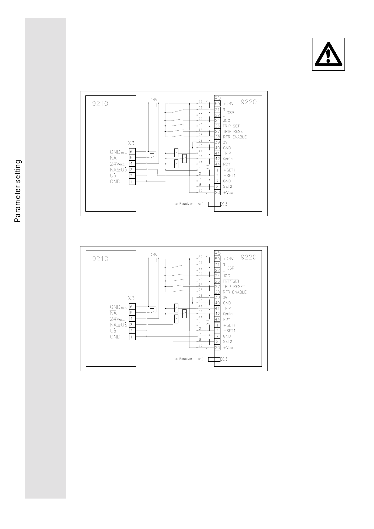
4.1.1. Wiring
Note
•
For radio interference suppression, all relays have to be equipped with freewheeling diodes!
•
all relays: R
a) Wiring for C005 = 11 und 21
< 1K
i
Ω
b) Wiring for C005 = 12, 13, 30 and for interface control
52
Page 55

4.1.2. Setting
These setting instructions are meant as guideline and must not
always decelerate the machine to standstill before reaching the
undervoltage threshold. The parameter setting of the codes, which
influences the DC-bus control during mains failure detection (C079,
C080, C228, C236, C237), depend on the size of the drive
configurations and the mechanical features of the system.
There are minimum speeds at which the energy of the mechanical
system is not high enough to compensate the losses which occur
during the controlled deceleration (switched-mode power supplies,
inverter, machines).
Aim:
•
The aim is to have a controlled speed deceleration that allows a
DC-bus voltage value which remains higher than the
undervoltage threshold for as long as possible.
As soon as the value falls below this threshold, pulse inhibit will
be set and the drive will coast to standstill.
•
The brake chopper should not be activated during the controlled
deceleration of the speed.
Therefore, the parameter setting of the DC-bus control should
be "softly". It is not very important whether the DC-bus can be
loaded to the voltage set under C236.
Required measuring units:
•
Oscilloscope,
at least 2 channels, if possible with memory.
Test set-up:
•
Connect channel 1 of the oscilloscope with X5,62 of the axis
module (speed monitor).
•
Connect channel 2 of the oscilloscope with X3,2 of the supply
module (DC-bus monitor).
•
If available, connect channel 3 of the oscilloscope with X5,44 of
the axis module (RDY-output).
Presettings:
1. Set the speed controller of the axis module drive configuration
as usual.
2. Activate the mains failure detection of the master drive (C229 =
-1-).
If the function is activated, the RDY-output changes from the
HIGH level to the LOW level. As soon as the speed is
decelerated to 0, the RDY-output re-changes to HIGH.
3. The relevant codes must be set as follows:
Code Presetting
C079
C080
C228
C229
C236
C237
-1150 s
1/10...1/20 of the natural slow-down time of the machine at
maximum operating speed
-1680 V
1000 rpm or more
53
Page 56

Setting course:
1. Select a medium speed as set value according to the occuring
speed range of the system.
2. Switch-off the mains.
The oscillogramme shows the reaching of the undervoltage
threshold on channel 2, the DC-bus voltage decreases slowly
(see fig. 1)
t1 = Start of the DC-bus control
= Undervoltage t hreshold
c
U
V
Br
C236
*
G
c
Vmin
t
1
fig. 1: Start of the setting
DC-bus voltage during DC-bus control
3. Increase C079 to reach the undervoltage threshold at a speed
as low as possible. For very small final speed values, you may
reduce C228.
4. Repeat steps 1.) to 3.) at maximum and minimum system
speed.
5. Reduce C080 at maximum system speed until the DC-bus
voltage does no longer overshoot the brake-chopper threshold
(see fig. 2).
You may also reduce C237 to limit the speed decrease during
deceleration.
reached
U
V
Br
C236
*
G
t1 = Start of DC-bus control
= Undervoltage t hreshold
c
c
Vmin
t
1
fig. 2: Real sett i ng
DC-bus voltage during DC-bus control
6. The increase of the Vz acceleration integrator C228 prolongs the
deceleration period.
7. Save the setting under C003.
reached
54
Page 57

Signal fow chart DC-bus control
55
Page 58

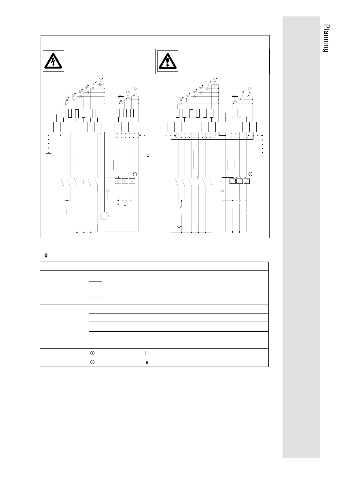
4.2. Homing mode
•
C250 Homing mode
In the homing mode (C250 = -0-) the increments of the master
frequency at the DIG.SET input are processed as a relative
change of angle. By activating the homing mode (C250 = -1-) it
is possible to refer to an absolute angle position of the motor
shaft. The homing mode can only be activated if the controller is
inhibitied. It is initiated by means of JOG function.
Functional sequence:
Start the homing mode by means of the JOG function enable.
The RDY signal indicates "not ready". The drive runs at the
selected JOG speed. After blocking the JOG signal (e.g. by
means of a proximity switch), the drive continues to run to the
home position and stops. The RDY signal indicates "ready".
If controller inhibit or QSP are activated during homing, the RDY
signal remains "not ready" until the homing process is finished.
Input signal JOG
Motor speed
Motor shaft
position
Output signal RDY
•
C252 Angle offset
JOG speed
0
o
360
Home position
any position
o
0
The shift range of the home position is one revolution of the
motor shaft. 360° is resolved into 2048 steps. The adjustment
can be made ON-LINE when the motor is running. The zero
pulse of the encoder emulation X4 is also resolved in 256 steps.
•
C254 Amplification of the angle controller
The angular controller is active when using a master frequency
DIG.SET input or if the homing mode is active. By selecting
Vpw=0, the angular controller is deactivated. In this case, the
master frequeny is processed as speed set value and not as set
angle increments. Before adjusting the amplification of the
angular controller, the speed controller must be optimized.
•
C159 Homing OK
C159 displays whether the homing was successful or not:
C159 = -1- homing successfully completed
C159 = -0- homing not completed
C159 may also be used for simulating a homing mode:
Set C159 = -1- and manually activate the angle offset under
C252.
t
56
Page 59

4.3. Further additional functions
•
C004 Switch-on display
Entering a code number under C004 determines which
parameter is to be displayed after switching-on.
•
C018 Chopper frequency
The chopper frequency determines the noise level. The chopper
frequency can either be 8 or 16 kHz. Changing the chopper
frequency changes the admissible permanent load of the axis
module.
•
C255 Following error limit
If an following error exceeds the value entered under C255
during master frequency operation (C005 = -13- or -21-) and an
amplification of the angle controller of C254 > 0, an internal
signal will be generated for the error status >>Following error
limit exceeded<< . If this signal is applied to the terminal Q
(X5,42) via C117, the Q
HIGH to LOW as soon as the set limit value is exceeded.
For following errors of more than 3188 increments, also the
RDY message will be set to LOW and >>following error<< will
be displayed.
(see page 74)
terminal will change its level from
min
min
57
Page 60

5. Serial interfaces
The 9200 servo axis modules can communicate via the serial
interfaces LECOM1 and LECOM2 with superimposed hosts (PLC
or PC) as well as Lenze operating units.
The LECOM1 interface (connector X1) is used to process the
LECOM A/B protocol. The LECOM1 interface can also be used to
connect devices to the RS 232C standard (LECOM-A) or to the RS
485 standard (LECOM-B). The interface is suitable for parameter
setting, monitoring, diagnosis and process control.
For more demanding applications, a field bus connecting module
can be used. For the parameter setting, this interface is generally
called LECOM2.
The following bus systems are available:
•
Interbus-S interface module 2110
•
Profibus interface module 2130
5.1. LECOM1 interface X1
The standard serial interface X1 fulfills the standard RS 232 C as
well as the standard RS 485.
Using the common RS 232 C interface, simple point-to-point
connection with a maximum cable length of 15 m can be achieved.
Almost every personal computer (PC) or other master system is
equiped with this interface. For several drives and larger distances,
the RS 485 interface must be used. Only two wires are used to
enable the communication of up to 31 controllers via a maximum
distance 1200 m.
The LECOM A/B protocol is based on the 1745 ISO standard and
supports up to 90 controllers. It recognizes faults and therefore
avoids the transmission of faulty data.
Pin assignment X1:
Pin Name Input/Output Explanation
1
+VCC15 Output Suppl y voltage +15V/50mA
2
RxD Input Data receiving line RS232C
3
TxD Output Data transmitting line RS232C
4
DTR Output Transmission control RS232C
5
GND -- Controller reference potential RS232C
6
DSR Input (unused)
7
T/R (A) Output /Input RS485
8
T/R (B) Output /Input RS485
9
+VCC5 Output Supply voltage +5V
58
Baud rate:
Protocol:
1200/2400/4800/9600 Bd (to be changed via C125).
LECOM-A/B V2.0
Page 61

5.2. LECOM status messages
•
C068 Operating state
Bit no. Signal
0, 1, 2, 3
4, 5, 6, 7
8
9
10
11
12
13
14
•
C069 Controller state
Bit no. Signal
0
1
2
3
4
5
6
7
15
Operating fault
Communication fault
RFR enable
Q
min
running
IMP
QSP
I
max
N
= N
act
set
BALARM
CALARM
PCHG
REMOT
AUTO
RESET
XXX
RFR
TRIP
•
C067 Fault numbers of the operating faults (see "Service")
--- OC1 OC2 OC5 OUE OH1 OH2 U15 CCr Pr Sd2 EEr UEr
0 111215225152707172829192
Further information on the serial communication LECOM1
(LECOM-A/B) can be obtained from the Operating Instructions
LECOM-A/B.
For extensions, the following modules are available:
2101 Interface with mains isolation for RS422/RS485
•
2122/2123 Interface for optical fibres (LECOM-LI)
•
59
Page 62

5.3. Table of attributes
If you want to programme the parameter setting or superimposed
drive and control functions yourself, the following table will inform
you about serial communication via LECOM1 (LECOM A/B) or
LECOM2.
Legend
Code Meaning
Code
DS
P/S
DT
DL
LCM-R/W
LCM1Form.
AIF-PZD
LCM2Index
Lenze code number
Data structure
E = Si ngl e variable (only one parameter element)
A = Array variable (several parameter element s can be selected by
the code for the preselecti on or by LECOM sub code.)
I = Image v ari abl e (several parameter elements can only be
selected by the code for preselection).
Parameter setting/c ont rol (corresponding to C001)
P = Parameter setting
S = Control
Data type
B8 = 1 byte bit coded
B16 = 2 byte bit coded
VS = ASCII string
FIX32 = 32-bit-value with sign;
decimal with four decimal pl aces
Examples:
1.2 = 12000
-10.45 = -104500
N16 = 16-bit value with sign; 0 = 0; 100% = 2
100% = 16384
-50% = -8192
Data length in byte
Access authorization for LECOM
Ra = Reading always perm i tted
W = Writing perm i tted under certain conditions
Wa = Writ i ng i s always permitted
LECOM A/B-format
(see technical description LECOM A/B)
Process data in the automation interface.
Mapping on LECOM2 process data channel i s possible.
PD = Process data
Number (index) under which the parameter is addressed when using
LECOM 2.
FIX32-dez
FIX32-dez
N16-dez
N16-dez
(e.g. operating mode, controll er i nhi bi t )
FFFE67CC
4000
E000
00002EEO
FIX32-hex
N16-hex
FIX32-hex
14
N16-hex
60
Page 63
Code P/S DS DT DE D/L LCM-R/W LCM
Form.
C000
C001
C002
C003
C004
C005
C009
C011
C012
C013
C017
C018
C022
C025
C026
C027
C028
C030
C031
C032
C033
C039
C040
C041
C042
C043
C045
C046
C047
C050
C051
C054
C056
C059
C060
C061
C067
C068
C069
C070
C071
C072
C079
C080
C081
C087
C088
C089
C091
C093
C094
C098
C099
C105
C117
C125
P E FIX32 1 4 Ra VD -- 24575
P E FIX32 1 4 Ra/Wa VD -- 24574
P E FIX32 1 4 Ra/W VD -- 24573
P E FIX32 1 4 Ra/W VD -- 24572
P E FIX32 1 4 -- VD -- 24571
P E FIX32 1 4 Ra/W VD -- 24570
P E FIX32 1 4 -- VD -- 24566
P E FIX32 1 4 Ra/W VD -- 24564
P E FIX32 1 4 Ra/W VD -- 24563
P E FIX32 1 4 Ra/W VD -- 24562
P E FIX32 1 4 Ra/W VD -- 24558
P E FIX32 1 4 Ra/W VD -- 24557
P E FIX32 1 4 Ra/W VD -- 24553
P E FIX32 1 4 Ra/W VD -- 24550
P I FIX32 1 4 Ra/W VD -- 24549
P I FIX32 1 4 Ra/W VD -- 24548
P I FIX32 1 4 Ra/W VD -- 24547
P E FIX32 1 4 Ra/W VD -- 24545
P E FIX32 1 4 Ra/W VD -- 24544
P E FIX32 1 4 Ra/W VD -- 24543
P E FIX32 1 4 Ra/W VD -- 24542
P E FIX32 1 4 Ra/W VD -- 24536
P E FIX32 1 4 Ra/W VD -- 24535
S E FIX32 1 4 Ra/W VD -- 24534
S E FIX32 1 4 Ra/W VD -- 24533
P E FIX32 1 4 Ra/W VD -- 24532
S E FIX32 1 4 Ra/W VD -- 24530
S E FIX32 1 4 Ra/W VD -- 24529
S E FIX32 1 4 Ra/W VD -- 24528
S E FIX32 1 4 Ra VD -- 24525
S E FIX32 1 4 Ra VD -- 24524
S E FIX32 1 4 Ra VD -- 24521
S E FIX32 1 4 Ra VD -- 24519
P E FIX32 1 4 Ra VD -- 24516
S E FIX32 1 4 Ra VD -- 24515
S E FIX32 1 4 Ra VD -- 24514
P E FIX32 1 4 Ra VD -- 24508
S E B16 1 2 Ra VH -- 24507
S E B8 1 1 Ra VH -- 24506
P E FIX32 1 4 Ra/W VD -- 24505
P E FIX32 1 4 Ra/W VD -- 24504
P E FIX32 1 4 Ra/W VD -- 24503
P E FIX32 1 4 Ra/W VD -- 24496
P E FIX32 1 4 Ra/W VD -- 24495
P E FIX32 1 4 Ra/W VD -- 24494
P E FIX32 1 4 Ra/W VD -- 24488
P E FIX32 1 4 Ra/W VD -- 24487
P E FIX32 1 4 Ra/W VD -- 24486
P E FIX32 1 4 Ra/W VD -- 24484
S E FIX32 1 4 Ra VD -- 24482
P E FIX32 1 4 Ra/W VD -- 24481
P E FIX32 1 4 Ra/W VD -- 24477
P E VS 1 6 Ra VS -- 24476
P E FIX32 1 4 Ra/W VD -- 24470
P E FIX32 1 4 Ra/W VD -- 24458
P E FIX32 1 4 Ra/W VD -- 24450
AIF-PZD LCM2
Index
61
Page 64

Code P/S DS DT DE D/L LCM-R/W LCM
Form.
C140
C153
C154
C158
C159
C161
C162
C163
C164
C165
C166
C167
C168
C180
C183
C184
C185
C186
C187
C200
C205
C228
C229
C236
C237
C249
C250
C252
C253
C254
C255
C300
C350
C351
C352
C353
C354
C355
C356
C357
C358
C359
C370
C380
C381
C382
C387
C388
C391
C400
C401
C402
C403
C404
C405
P E FIX32 1 4 Ra/W VD -- 24435
P E FIX32 1 4 Ra/W VD -- 24422
P E FIX32 1 4 Ra/W VD -- 24421
S E FIX32 1 4 Ra VD -- 24417
P E FIX32 1 4 Ra/W VD -- 24416
P E FIX32 1 4 Ra VD -- 24414
P E FIX32 1 4 Ra VD -- 24413
P E FIX32 1 4 Ra VD -- 24412
P E FIX32 1 4 Ra VD -- 24411
P E FIX32 1 4 Ra VD -- 24410
P E FIX32 1 4 Ra VD -- 24409
P E FIX32 1 4 Ra VD -- 24408
P E FIX32 1 4 Ra VD -- 24407
P E FIX32 1 4 Ra/W VD -- 24395
P E FIX32 1 4 Ra/W VD -- 24392
P E FIX32 1 4 Ra/W VD -- 24391
P E FIX32 1 4 Ra/W VD -- 24390
P E FIX32 1 4 Ra/W VD -- 24389
P E FIX32 1 4 Ra/W VD -- 24388
P E VS 1 14 Ra VS -- 24375
P E OS 1 0 Ra VO -- 24370
P E FIX32 1 4 Ra/W VD -- 24347
P E FIX32 1 4 Ra/W VD -- 24346
P E FIX32 1 4 Ra/W VD -- 24339
P E FIX32 1 4 Ra/W VD -- 24338
P E FIX32 1 4 Ra/W VD -- 24326
P E FIX32 1 4 Ra/W VD -- 24325
P E FIX32 1 4 Ra/W VD -- 24323
P E FIX32 1 4 Ra/W VD -- 24322
P E FIX32 1 4 Ra/W VD -- 24321
P E FIX32 1 4 Ra/W VD -- 24320
S E FIX32 1 4 Ra VD -- 24275
P E FIX32 1 4 Ra VD -- 24225
P E FIX32 1 4 Ra VD -- 24224
P E FIX32 1 4 Ra/W VD -- 24223
P A FIX32 8 4 Ra VD -- 24222
P A FIX32 8 4 Ra VD -- 24221
P A FIX32 8 4 Ra VD -- 24220
P A FIX32 8 4 Ra VD -- 24219
P E FIX32 1 4 Ra/W VD -- 24218
P A FIX32 3 4 Ra VD -- 24217
P E FIX32 1 4 Ra VD -- 24216
P E FIX32 1 4 Ra/W VD -- 24205
S E I16 1 2 Ra/W VH PZD 24195
S E I16 1 2 Ra VH PZD 24194
S E I16 1 2 Ra VH PZD 24193
S E I16 1 2 Ra VH PZD 24188
S E I16 1 2 Ra/W VH PZD 24187
S E U16 1 2 Ra VH PZD 24184
P E FIX32 1 4 -- VD -- 24175
P E FIX32 1 4 -- VD -- 24174
P E FIX32 1 4 -- VD -- 24173
P E FIX32 1 4 -- VD -- 24172
P E FIX32 1 4 -- VD -- 24171
P E FIX32 1 4 -- VD -- 24170
AIF-PZD LCM2
Index
62
Page 65

6. Code table
The following table shows which settings can be performed with
which codes. Detailed explanation about the codes and the
functions which can be achieved, are described in special chapters.
For the acceptance of parameters see page 41.
How to read the code table:
Column Short form Meaning
Code C000
C017*
C043 (L)
Parameter
Acceptance ON-LINE
-0-
SH + PRG
Code digit of the standard code set
Code digit of the extended code set
Code digit can only be reached via the LECOM interface; code
is not displayed
The factory setting is printed in bold.
Unit immediately accepts new parameter
Unit accepts new parameter after pressing SH+PRG
Unit accepts parameter only if the controller is inhibited when
pressing SH+PRG.
Code Name Parameter Accept-
ance
C000
C001
C002
C003
C004
Code set -0-
-1-
-2-
-9-
-11-
-P-
xxx
Operating
mode
Load parameter
set
Store
parameter set
Switch-on
display
-0-
-1-
-2-
-3-
-4-
-5-
-6-
-7-
-0- Factory setting
-1- Parameter set 1
51
Standard code set read only
Standard code set
Extended code set
Service code set (service password
neccessary)
Code set for
automation module
Password request
Enter password
Control: Parameter setting:
Terminals Keypad
Keypad Keypad
Terminals LECOM1
LECOM1 LECOM1
Terminals LECOM2
LECOM2 LECOM2
LECOM2 Keypad
LECOM2 LECOM1
Code no. for parameter displayed
after first switch-on
SH+PRG
password
SH+PRG
SH+PRG
SH+PRG 57
see
page
45
45
63
Page 66

Code Name Parameter Accept-
ance
C005*
Configuration
-11-
-12-
-13-
-20-
Speed control
n
: analog, X5, terminals 7, 8
set
Speed control
: analog, X5, terminals 1, 2
n
set
Speed control
n
: Dig. Set X2
set
Speed control with corresponding
variable torque limitation
n
: analog X5, terminals 1, 2
set
M
: analog X5, terminals 7, 8
set
-21-
Speed control with corresponding
variable torque limitation
n
: Dig. Set X2
set
M
: analog, X5, terminals 7, 8
set
-30-
-33-
Torque control
M
: analog X5, terminals 1,2
set
Torque control with corresponding
variable speed limitation
n
: analog X5, terminals 7, 8
set
M
: analog X5, terminals 1,2
set
C009*
Controller
address
1
Bus participant number LECOM-A/B
Setting range: 1 - 99
SH+PRG
10, 20, 99 reserved for broadcast
C011
C012
n
(maximum
max
speed)
T
(acceleration
ir
time)
3000
0.01
Setting range: 100...8000 rpm
Step: 1 rpm
Setting range: 0.00...990 s
Step: 0.01s from 0.00...1s
ON-LINE
ON-LINE 48
0.1s.from 1...10s
1s from 10...100s
10s from 100...990s
C013
T
(deceleration
if
time)
0.01
Setting range: 0.00...990 s
Step: 0.01s from 0.00...1s
ON-LINE 48
0.1s.from 1...10s
1s from 10...100s
10s from 100...990s
C017*
Q
min
-treshold
10
Setting range: 0...8000 rpm
ON-LINE
Step: 1 rpm
When the motor speed is lower than
the Q
-treshold, output Q
min
min
is set
to 0 V.
-0-
-1-
f
chop
f
chop
= 8 kHz
= 16 kHz
C018*
C022
f
(Chopper
chop
frequency)
I
(maximum
max
xxx Step: 0.1 A ON-LINE 48
current)
see
page
46
57
64
Page 67

Code Name Parameter Accept-
ance
C025*
C026*
C027*
C028*
C030*
C031*
C032*
C033*
C039
C040
Encoder -0-
-1-
-3-
-5-
-13Encoder
constant
Encoder setting -0-
Encoder setting2-0-
Encoder
simulation
n
offset
Ratio
numerator
Ratio
denominator
JOG speed
RFR (controller
enable)
-0-
-1-
-2-
-3-
-4-
1.000
1.000
-1-
-2-
-3-
-40
0.1
0.1
20
-0-
-1-
noe encoder selected for setting
bipolar set value X5, terminals 1, 2
Dig. Set master frequency X2
unipolar set value X5, terminals 7, 8
act. resolver value X3
no encoder constant
512 increments/revolution
1024 increments/revolution
2048 increments/revolution
4096 increments/revolution
no setting required
Setting range: -5...0...+5
LECOM: -5000...0...+5000
Step: 0.001
Adjustable speed ratio between slave
and master drive n
using the Dig. Set input.
no setting required
Setting range: -5...0...+5
LECOM: -5000...0...+5000
Step: 0.001
Second adjustable speed ratio for the
Dig. Set input. The controller is
enabled (changing the parameter
form C027 to C028) via code C 140.
256 increments/revolution
512 increments/revolution
1024 increments/revolution
2048 increments/revolution
Setting range: -1000...+1000
Step: 10 mV
Offset adjustment of the selected
analog speed set value input
Setting range: -3.2767...+3.2767
Step: 0.0001
Numerator of the gearbox factor for
the Dig. Set input. The total ratio can
be obtained from the follow. formula:
⋅⋅
C027 C032
=
C033
Due to an internal limitation, only
values from V= -5.000...+5.000 can
be realized.
Setting range: +0.0001...+3.2767
Step: 0.0001
Denominator of the gearbox factor for
the Dig.Set input (formula: see C032)
Setting range: -n
Step: 1 rpm
Controller inhibited
Controller enabled
set/nmaster
or V =
...+n
max
when
C028 C032
C033
max
SH+PRG 46
SH+PRG 46
ON-LINE 46
ON-LINE 46
SH+PRG
ON-LINE
ON-LINE 46
ON-LINE 46
ON-LINE
SH+PRG
see
page
65
Page 68

Code Name Parameter Accept-
ance
C041
C042
CW/CCW -0-
-1QSP (Quick
stop)
-0-
-1-
Set value not inverted
Set value inverted
Quick stop inactive
Qick stop active (The speed set value
SH+PRG
SH+PRG
goes to digital 0 with the quick stop
deceleration time under C105)
C043
(L)
C045
C046
Trip Reset -0-
-1JOG enable -0-
-1n
set
1
xxxx Setting range: -n
(speed set
value 1)
no act. fault/ reset fault
actual fault
JOG set value inhibited
JOG set value enabled
...+n
max
max
Step: 1 rpm
Display of the externally adjusted
ON-LINE
SH+PRG
ON-LINE
speed set value. For keypad and
LECOM control: on-line set value
selection
C047
M
max
(torque limit)
xxx Setting range: 0...100.0% or
-100.0...+100.0% for torque control
ON-LINE
Step: 0.1%
The maximum torque which can be
obtained, depends on the type of
servo motor and the axis module
employed
C050
n
2 (speed
set
set value 2)
_xxxx Setting range: -n
Step: 1 rpm
max
...+n
max
read only
Effective speed set value at speed
controller input
C051
C054
n
(motor
act
shaft speed)
I
mot
(motor current)
_xxxx Setting range: -9765...9765 rpm
Step: 1 rpm
xxx Setting range: 0.0...maximum
current
read only
read only
Step: 0.1 A
The displayed value is calculated
from the sinus oscillations of the
current. the difference to the actual
effective motor current is approx.
10%. In the field weakening range, a
larger difference may be possible.
C056
M
set
(effective
torque set
value)
xxx Setting range: -100.0...+100.0%
Step: 0.1%
The maximum torque which can be
obtained (100%) depends on the type
read only
of servo motor and the axis module
employed
C059*
Pole pair
xx read only
number
C060*
Rotor position xxxx Setting range: 0...2047 increments
read only
Step: 1 increment
see
page
66
Page 69

Code Name Parameter Accept-
ance
C061
Utilization I x t xxxx Setting range: 0.0...+100.0%
read only
Step: 0.1%
The indicated value is determined by
the current-time integral I x t of the
controller current. When reaching
100% the I x t monitoring sets
overload trip
C067
C068
Fault diagnosis xxx see under "Service" 74
Operating state see under "Service" read only 59
(L)
C069
Controller state see under "Service" read only 59
(L)
C070
V
(gain of
pn
speed
30
Setting range: 0...500
Step: 1
ON-LINE 49
controller)
C071*
T
n
(Integral action
time of speed
10
9999
Setting range: 2.5...100 ms
Step: 0.5 ms
Deactivate integral component
ON-LINE 49
controller)
C072*
k
d
(differential
0
Setting range: 0...5
Step: 0.1
ON-LINE 49
amplification of
speed
controller)
C079*
C080*
V
p
(Vz-controller)
T
n
1000
1.0 s
Setting range: 0...9000
ON-LINE 53
Step: 1
Setting range: 0.01...150 ON-LINE 53
(Vz-controller)
C081*
C087
C088
Rated motor
power
Rated motor
speed
Rated motor
current
xxx.x Setting range: 0.1...650 kW
Step: 0.1 kW
xxxx Setting range: 300...6000 rpm
Step: 1 rpm
xxx Setting range: 0.1A...max. controller
current
Step: 0.01 A
C089
C091
Rated motor
frequency
cos ϕ Motor
xxx.x Setting range: 10.0...300.0 Hz
Step: 0.1 Hz
x.xx Setting range: 0.50...0.99
Step: 0.01
C093*
Controller
xx read only
identification
C094*
Pass word
0
enter any password (0...999)
SH+PRG 42
no password defined
C098
Language -0-
-1-
-2-
German
English
French
Note:
The setting will not be overwritten
when loading the factory setting!
C099*
C105
Software
version
Quick stop
deceleration
time T
QSP
92_5.x Number to identify the software
version
0.01
Setting range: 0.00...990 s
Step: 0.01 s from 0.00...1 s
0.1 s from 1...10 s
read only
ON-LINE 48
1 s from 10...100 s
10 s from 100...990 s
see
page
47
67
Page 70

Code Name Parameter Accept-
ance
C117*
C125*
C140*
C153*
C154*
C158*
C159*
Assignment of
Qmin terminal
Baud rate
Enable encoder
setting
Minimum limit
monitor 1
Maximum limit
monitor 1
Actual following
error
Homing OK
-0-
-1-
-2-
3000
xxxx Display range: -3188...3188
Terminal X5,42 has the function:
Qmin
Terminals X5,42 has the function:
following error limit reached
If code C117 is set to -1-, the terminal
X5,42 changes from HIGH to LOW
level as soon as reaching the
following error limit C255.
Terminal X5,42 has the function:
controller enable.
If code C117 is set to -2- the High
level of terminal X5,42 displays an
pulse enable of the rectifier.
Note:
If the function pulse enable is
assigned to terminal X5,42 to control
a mechanical brake please note that
you set Code117 to -2controlling the brake. The loading of
the factory setting deactivates this
function.
-0-
9600 baud
-1-
4800 baud
-2-
2400 baud
-3-
1200 baud
-0-
C027 active
-1-
C028 active
0
Setting range: 0 rpm...C154
Step: 1 rpm
Setting of the minimum limit to give
the speed to monitor output 1.
Speeds, the absolute number of
which is smaller than the minimum
limit, generate 0 V on the monitor
output 1 of terminal 62.
Setting range: C153...9000 rpm
Step: 1 rpm
Corresponds to an output voltage of
10 V at terminal 62. Speeds > C154
generate a 10 V level on the monitor
output.
increments
Step: 1 increment
-0-
Homing not finished
-1-
Homing successfully finished
The status -1- can also be set.
Therefore it is possible after mains
connection to start without homing, in
the homing mode (C250 = 1) with
Dig.-Set operation. The angular offset
C252 is then set to 0.
before
SH+PRG
SH+PRG 46
ON-LINE
ON-LINE
read only
SH+PRG
see
page
68
Page 71

C161
...
C168
(L)
C200
(L)
Saved fault
messages
Software
version
Display of the last eight fault
messages saved under C068,
readable only via LECOM. The last
fault reset is in C161.
Display of the software version,
readable only via LECOM
read only
read only
69
Page 72

Code Name Parameter Accept-
ance
C228*
Acceleration
time (V
-
z
controller)
0.01
Setting range: 0.00...990 s
Step: 0.01 s from 0.00...1 s
0.1 s from 1...10 s
ON-LINE 53
1 s from 10...100 s
10 s from 100...990
C229*
Activation
V
-controller
z
-0-
Mains failure detection with V
not activated
Mains failure detection with V
-1-
-control
z
-control
z
activated
C236*
C237*
C249
(L)
C250*
C252*
V
set
(Vz-controller)
Influence of
V
-control
z
LECOM1-code
bank
Homing mode
Angle offset
600
1000
-0-
-1-
-2-
-3-
-4-
-5-
-6-
-7-
-0-
-1-
0
Setting range: 300...900 V
Step: 1 V
Setting range: 1...8000 rpm
Step: 1 rpm
C000 to C255
C250 to C505
C500 to C755
C750 to C1005
C1000 to C1255
C1250 to C1505
C1500 to C1755
C1750 to C2000
not active
active
Setting range: 0...2047
ON-LINE 53
ON-LINE 53
SH+PRG
ON-LINE 56
Step: 1
C253*
Speedproportional
angle offset
8.5
Setting range: -819.1...+819.1 incre-
ments (at 4000 rpm)
Step: 1
ON-LINE
Possibility to correct an angular
offset, which is proportional to the
speed and depending on the cycle
time. The setting refers to an
incremental deviation of 4000 rpm.
C254*
V
pw
14
Setting range: 0...16
ON-LINE 56
Step: 1
C255*
Following error
limit
10
Setting range: 10...3071 increments
Step: 1 increment
ON-LINE 57
see
page
53
56
70
Page 73

Code Name Parameter Accept-
ance
C370*
C380
(L)
C381
(L)
C382
(L)
C387
(L)
C388
(L)
C391
(L)
Automation
interface
RP-set speed
(corresponds to
C046)
RP-n
set2
(corresponds to
C050)
RP-actual
speed
(corresponds to
C051)
RP-set torque
(corresponds to
C056)
RP-M
limit
(corresponds to
C047)
RP-act. angle
(corresponds to
C060)
_xxxxx Display range: -26844...+26844
_xxxxx Display range: -26844...+26844
_xxxxx Display range: -32767...+32767
_xxxxx Display range: -32767...+32767
_xxxxx Display range: -32767...+32767
xxxxx Display range: 0...65535
Automation interface active
-0Automation interface inactive
-1-
The automation communication must
be activated when using an automation module or a field bus connection LECOM2. If the communication is
enabled, without communicating to
the other side, the controller remains
inhibited. The communication via the
automation interface can be activated
independently of the operatíng mode
C001 when the controller is inhibited
(C040 = 0).
Caution!
To ensure a faultless initialization, the
LECOM interface may only be
accessed after one sec.
Note:
The setting will not be overwritten
when loading factory setting!
(8000 rpm = 26844)
Step: 1
(8000 rpm = 26844)
Step: 1
(9765 rpm = 32767)
Step: 1
Note:
Quick display without time message!
(100% = 32767)
Step: 1
Step: 1
(360° = 16384)
Step: 1
ON-LINE
read only
read only
read only
ON-LINE
read only
see
page
71
Page 74

72
+SET1
-SET 1
SET2
DIG.SET
Monitor1
Q
min
Encoder
simulation
X5
1
2
X5
8
7
Constant
C026
X2
Homing mode
C250
C252
Home position shift
C255
X5
62
X5
42
X4
C027
Follo win g
error
C117
D if fe r e nt ia l a m p lif ier
unipolar
Setting
C028
1
0
C140
w
f
1
Q
min
0
2
Pulse enable
8 bit
A
f
C032
C033
Target window
n
D
Setting
dw
dt
10 bit
A
10 bit
A
Angle
set
thre s h o ld
C154
C153
C017
C030
C046
n
JOG-enable
24 21 22
C045
1
n
set
T
n
C071
n-controller
k
d
C072
nn
offset max
dw
w
dt
C254
w
11,12,20,21
C380
V
30,33
n
C051
+
pw
act
+
13,21
+
Angle
controlle r
n
act
11,12,20,3 3
30
D
D
C031
12,20
11,33
+
+
Lim it
JOG value
C060
C056
M
C011
C039
Configuration
v
C070
Angle
set
C005
pn
act
CW CC W
CW/
CCW
C041
± 1
11,12,13
20,21
30,33
QSP
CW/CCW
Set value
inte grato r
100 %
Resolver evaluation
QSP QSP
C042
C012 C013
T
ir
n
C050
C388
set
D
C105
T
if
2
R
Factory setting
Set value influence,
when using
module 2211
verwendet w ird
T
M
max
C047
lim it
X3
7. Signal flow chart axis modules
Set value conditioning
Speed control
R
Page 75

Torque and current control
ASM
Monitoring
Current transformer
Resolver wire breakage
f
C018
RDY
U
V
W
3
IGB Ts
Power stage
chop
PWM
i-con t rolle r
i
mot
C054
I
Controller identification
Heat sink temperature
Pulse inhibit
act
i
LED IMP
max
-1
LED I
44
C093
IM P
LED RDY
On-delay
TRIP
41
i=0
Short circuit
Sd2
OH2
Fault memory
RDY
LU
C067
EEr
OH1
OC5
OUE
C061
Ixt utiliz a tio n
Earth fault
OC1
UEr
OC2
Pr
CCr
U15
+15V
Supply voltage
Current vector
calculation
C022
C087
max
I
Rated speed
Motor nameplate
C088
Rated current
C059
C091
C089
cos phi
Rated frequ ency
8 bit
Pole pa ir nu m ber
63
X5
Monitor2
RFR
C040
STP-key
28
X5
RFR
Status
supply module
X6
State bus
X5
26
27
X5
Trip Set
Trip Reset
73
Page 76

Service
1. Monitoring messages
The servo drives of the 9200 series have numerous monitoring
functions, to protect against non-permissible operating conditions.
When such a protective function is activated, it either causes a
corresponding message on the controller display and pulse inhibit
(IMP) or, in addition (TRIP) setting. The type of fault is immediately
displayed. After having removed the fault, the pulse inhibit is
released automatically. Faults, however, causing a TRIP setting
must be reset und C067 by pressing SH+PRG or by a high signal
on input X5, terminal 27, TRIP reset.
1.1. Monitoring without activating pulse inhibit
•
Following error
The increments of the master frequency set value (Dig.Set) are
interpreted as angle increments (condition: V
cannot follow the set increments the message "Following error"
will be displayed as soon as a following error exceeds 3188
increments (2048 increments ∉ 360° at the motor shaft). The
error message disappears when the motor reaches the set
angle. A following error >3188 increments cannot be corrected.
>0). If the drive
pw
1.2. Monitoring with activating pulse inhibit
•
LU Undervoltage
The mains voltage of the supply module is monitored by
measuring the DC bus voltage. If the DC bus voltage decreases
below 330V ± 4%, the servo controllers cannot continue to
operate. The axis modules are inhibited via the State Bus. If the
mains voltage increases above 430V ± 3% again, the axis
modules are released again.
1.3. Monitoring with TRIP setting
•
OC1 Short circuit
OC1 is displayed if the current controller of the axis modules is
not able to limit the output current of the controller to the peak
current. Check if there is a short circuit in the motor or the motor
supply cable.
•
OC2 Earth fault
An earth fault current is detected if the total of the phase output
current is not 0. Check if there is an earth fault in the motor or
the motor supply cable.
Caution
Before switching on the mains again, it must be ensured that the
earth fault has been removed. The inverter free wheeling diodes
may be destroyed by earth faults.
:
74
Page 77
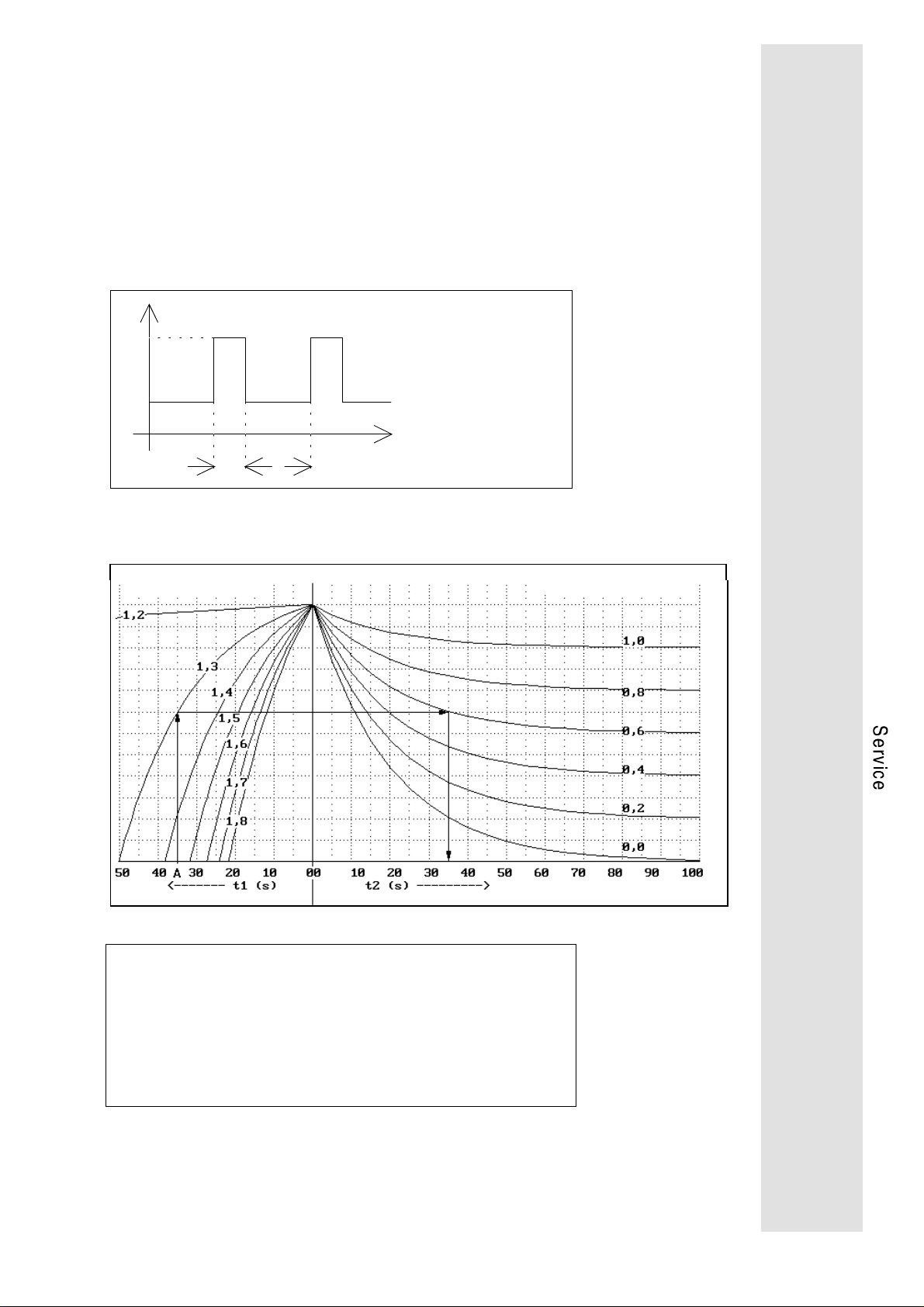
•
OC5 Overload axis module (I · t)
The servo controllers can be overloaded up to their peak current
for a certain period of time. The possible duration of overload
without Trip setting depends on its intensity. When exceeding
the time limit, the fault OC5 "overload" is displayed. The
current/time ratios that do not lead to Trip setting are shown in
the overload diagrams below. These overload diagrammes
show permissible overcurrents, necessary recovery times and
load cycles. Take into consideration that the rated currents of
the axis modules depend on the chopper frequency set under
C018 (see Technical data, page 6).
1
I
I
2
I1 > I
: overload current
nom
I2 < I
: base load current
nom
t1: duration of the overload
t2: duration of the base load
1
t
Overload chart for f
Parameter I1/Irated Parameter I2/Irated
chop
2
t
= 8 kHz
Example A
given: f
= 8kHz
chop
overload I1 = 1,3 . I
base load I2 = 0,6 . I
rated
rated
,t1 = 35s
required: minimum duration of the base load t
result: t2 = 35s
2
75
Page 78
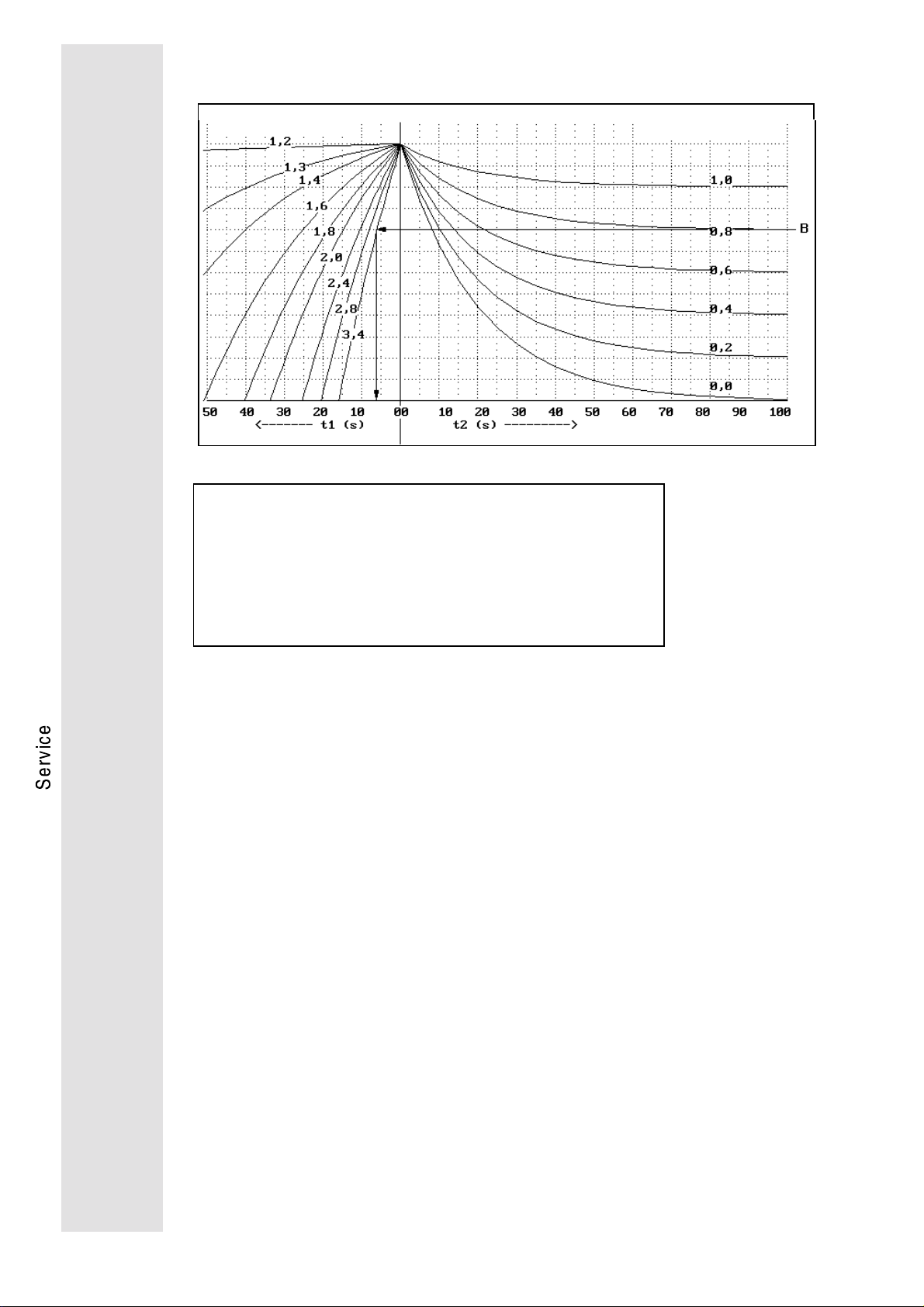
Overload chart for f
Parameter I1/Irated Parameter I2/Irated
Example B
given: f
chop
overload I2 = 0,8 . I
overload I
= 16kHz
chop
= 16kHz
1
= 3,4 . I
rated
rated
required: maximum duration of the overoad t
1
result: t1 = 7s
OUE Overvoltage
If the DC bus voltage exceeds 750 V due to :
excessive mains voltage or
•
excessive brake energy,
•
the fault OUE "overvoltage" is displayed. In the case of excessive
brake energy, the deceleration times T
and (or) T
if
QSP
must be
increased. If necessary, install an external brake resistor.
OH1 Overtemperature supply module
The temperature monitoring on the supply module detects
overtemperatures of the heat sink, the mains input bridge, the
brake chopper and the internal brake resistors. Possible reasons
are:
overload of the supply module (supply module power < total
•
axis module power).
blower defective or insufficient
•
ambient temperature > 45°C.
•
76
OH2 Overtemperature heat sink axis module
The heat sink is monitored by a thermal contact. If the fault OH2 is
displayed, either the ventilation is not sufficient or defective, or the
ambient temperature is > 45°C. Fault reset is only possible after the
heat sink temperature has been reduced below 45°C.
Page 79

EEr External TRIP
The voltage at the TRIP-SET input X5 terminal 26 must be < 5V.
Otherwise, the external TRIP will be set.
SD2 Wire breakage resolver or resolver cable
The electrical resistance of the resolver cables is monitored. If the
line resistance is too high due to a line breakage or an interruption
in the resolver, fault SD2 "wire breakage" is displayed.
U15 Supply voltage interrupted
Check the Vcc-15V connection X5 terminal 20 for external short
circuit.
CCr System fault
Programme sequence error in the micro processor. A system fault
occurs with interference in the electronics caused by incorrect
screening or non-screened cables or due to ground or earth loops
in the wiring. The fault may also occur after short mains
interruptions (t < 1 min) if the controller was switched off while there
was another non-acknowledged fault.
Pr Parameter loss
Program sequence error in the microprocessor which is caused by
interference in the electronics due to incorrect screening or nonscreened cables or ground or earth current loops in the wiring. The
interference resulted the loss of the stored parameters. After TRIP
reset and before enabling the controller again, a new parameter
setting is required.
CEO
Communication error with the automation module. The error occurs
when the automation module is activated by C370-1, but the
communication is interrupted.
UEr Unknown fault
This fault occurs in the fault memory if the hardware monitoring
sets TRIP, however, the software cannot identify the fault (e.g. in
case of interrupted supply voltage.
77
Page 80

2. LED displays
The LED displays clearly indicate the momentary operating state of
the controller even from greater distances. The axis modules are
provided with 3 LEDs in the operating terminal, the supply has 2
LEDs at the front side.
2.1. LED supply module
RDY Ready to operate
The LED is illuminated after the ON-delay has passed and no fault
was detected. RDY is not illuminated if a fault was detected.
BR
Brake chopper active
on
The LED is illuminated if the DC bus voltage is increased above a
threshold by absorbing regenerated energy and then dissipated
through the brake resistor.
2.2. LED axis module
RDY Ready to operate
The LED is illuminated if the ON-delay has passed and no fault was
detected. RDY is not illuminated if a fault was detected or homing is
not finished or the DC bus control is active or a following error is
active.
I
max
The LED is illuminated when reaching the maximum controller
current or the set torque limit.
IMP
Pulse inhibit. The LED is illuminated if the inverter is inhibited. The
inverter is inhibited if the terminal 28 is low the STOP key is
pressed, inhibit avtivated by communication or if a fault is detected.
RDY I
on off off Controller is ready to operate, the controller is enabled
max
IMP
on off on Controller is ready to operate, however, i t is not enabled
on on off Speed controller is limited:
the controller supplies t he
First commissioning
If the motor speed remains at 50...300 rpm even at high
set value and low load, the mot or connection cables U and
V must be exchanged.
off off on Controller is not ready to operate. In case of fault, the t ype
of fault is display ed.
off off off Maximum following error, homi ng not finished, active DC -
bus control (see above)
off on off The maximum following error occured at master frequency
coupling and the controller reaches the set current limit.
maximum current
set
:
78
Page 81

3. Checking the power stage
The measurements described below are to be carried out only by
skilled specialists. Use a digital voltmeter. The measuring values
indicate the nominal value. If they are different from your measurements, there is a defect.
3.1. Checking the mains rectifier
•
Disconnect the controller from the mains.
Caution!
Wait 5 minutes until the DC-bus is discharged no load!
•
Measure directly at the power terminals.
Measurement Measuring point Measuring value
≈
Diodes in forward
direction
Diodes in reverse
direction
L1 → +UG
L2 → +UG
L3 → +UG
-UG → L1
-UG → L2
-UG → L3
+UG → L1
+UG → L2
+UG → L3
L1 → -UG
L2 → -UG
L3 → -UG
0.4V
≈
0.4V
≈
0.4V
≈
0.4V
≈
0.4V
≈
0.4V
high resistance (OL)
high resistance (OL)
high resistance (OL)
high resistance (OL)
high resistance (OL)
high resistance (OL)
3.2. Checking the output stage
•
Disconnect the controller from the mains.
Caution!
Wait 5 minutes until the DC-bus is discharged!
•
Measure directly at the power terminals.
Measurement Measuring point Measuring value
≈
Inverter diode in forward
direction
Inverter diode in reverse
direction
Inverter diode in forward
direction
Inverter diode in reverse
direction
U → +UG
V → +UG
W → +UG
UG → U
UG → V
UG → W
-UG → U
-UG → V
-UG → W
U → -UG
V → -UG
W → -UG
0.4V
≈
0.4V
≈
0.4V
high resistance
high resistance
high resistance
≈
0.4V
≈
0.4V
≈
0.4V
high resistance
high resistance
high resistance
79
Page 82

Index
A
Acceleration time
cceptance
A
direct
41
On-line
with SH + PRG
with SH + PRG with controller
inhibit
Ambient temperature 6
Amplification of the angle controller
56
Amplification of the difference
component of the speed controller
Analog set value selection
Angle offset
Automation interface 71
Axis module 7
41
42
48
41
22
56
B
Basic parameter setting 45
Baud rate
Brake chopper active
Brake resistor
external 33
Brake resistor
external 18
internal 20
58
78
49
C
CEO
77
Change parameters 41
Checking the mains rectifier 79
Checking the output stage 79
Code table 63
Commissioning 45
cos ϕ motor
47
D
DC-bus control 50
Deceleration time
Diagnosis 58
48
E
Earth fault
Electromagnetic combatibility 14
Electromagnetic compatibility 14
EMC 14
Enclosure 6
Encoder simulation
Extended code set 41
External Trip
74
25
77
F
Following error
Fuses 34
74
G
Gain adjustment
Gearbox factor 46
H
Homing mode
56
I
Installation
electrical 11
mechanical 10
49
80
Page 83

Integral action time of the speed
controller
Interference immunity 34
49
K
Keypad control 45
L
LCD display 40
LECOM1 58
LECOM2 58
LECOM-LI 59
LED
Axis module 78
Supply module 78
Mains isolation 14, 15, 59
Mains status 20
Mains voltage 6
Master frequency
Master frequency provision 46
Master frequency selection
Maximum current
Maximum speed
Monitoring 58
Monitoring messages 74
Motor connection 17
Motor nameplate data 47
Motors 39
46
48
48
N
Noise immunity 6
24
M
Mains and DC-bus monitoring 20
Mains connection 17
Mains failure detection 50
activation 51
O
ON-LINE
Optical fibres 59
Overload axis module
Overtemperature heat sink
Overtemperature supply module
Overvoltage
41
75
76
76
P
Parameter setting 40, 41, 58
Password 45
Peak power 6
Permanent brake power 18
Planning 5
Pollution strength 6
Power connections 17
Power stage 79
Q
Quick stop deceleration time
48
R
Rated motor current
Rated motor frequency
Rated motor speed
Ready to operate
relative humidity 6
Resolver
RFI filter 34
RS 232 C 58
RS 485 58
25
47
47
47
78
76
S
Save parameters 42
Screening 14
serial communication 60
Setting of speed controller 49
Short circuit
Standard code set 45
State bus 21
74
81
Page 84

Supply modules 6
Supply voltage interrupted
Switch-on display
System cables 34
for control terminal block 34
for power supply 37
for resolver 36
supply of fan and brake 38
System fault
Systemcables
for master frequency selection 35
57
77
77
T
Table of attributes 60
Terminal control 45
TRIP setting 74
U
Undervoltage
Unknown fault
74
77
W
Wire breakage resolver
77
82
 Loading...