

Page 1

Owner Handbook
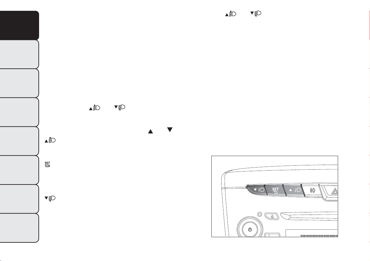
Page 2

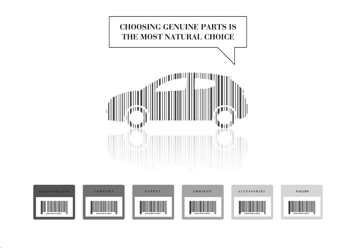
WHY CHOOSING
GENUINE PARTS
We really know your car because we invented, designed and built it: we really know every single detail.
At Lancia Service authorised workshops you can find technicians directly trained by us, offering quality
and professionalism for all service operations.
Lancia workshops are always close to you for the regular servicing operations, season checks
and practical recommendations by our experts.
With Lancia Genuine Parts you keep the reliability, comfort and performance features
of your new car unchanged in time: that's why you bought it for.
Always ask for Genuine Parts for the components used on our cars; we recommend them because
they come from our steady commitment in research and development of highly innovative technologies.
For all these reasons: rely on Genuine Parts, because they are the only ones designed
by Lancia for your car.
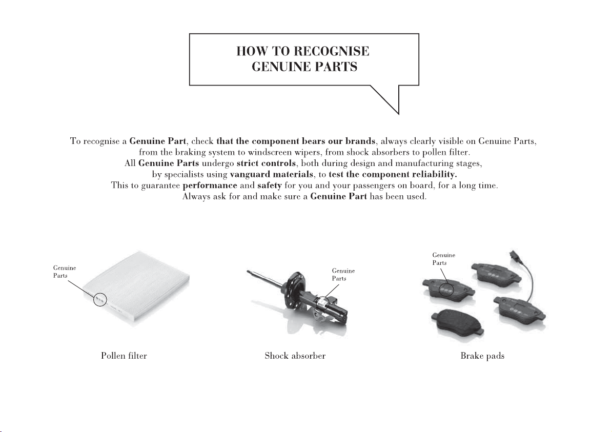
SAFETY:
BRAKING SYSTEM
ENVIRONMENT: PARTICULATE FILTERS,
CLIMATE CONTROL MAINTENANCE
COMFORT: SUSPENSION
AND WINDSCREEN WIPERS
PERFORMANCE: SPARK PLUGS,
INJECTORS AND BATTERIES
LINEACCESSORI
ROOF RACK BARS, WHEEL RIMS
Page 3
Page 4
Page 5

Dear Customer,
We would like to congratulate and thank you for choosing LANCIA.
We have written this handbook to help you get to know all the features of your car and use it in the best possible
way.
You are recommended to read it right through before taking to the road for the first time.
It contains important information, advice and instructions for the use of the car which will help you get the very
best out of your LANCIA. This booklet also provides a description of special features, essential information for the
correct care and maintenance of your LANCIA as well as safe driving tips.
Carefully read the warnings and indications marked with the following symbols:
personal safety;
car safety;
environmental protection.
The enclosed Warranty Booklet lists the services that LANCIA offers to its Customers:
❒ the Warranty Certificate with terms and conditions for maintaining its validity;
❒ the range of additional services available to LANCIA Customers.
We are sure that these will help you get in touch with your new car and further appreciate it and the care provided
by the people at LANCIA.
Enjoy reading. Happy motoring!
This Owner Handbook describes all the versions of the LANCIA Ypsilon. As a
consequence, you should only consider the information which is related to the trim
level, engine and version that you have purchased. All data contained in this
publication are purely indicative. Fiat Group Automobiles can modify the
specifications of the vehicle model described in this publication at any time, for
technical or marketing purposes. For further information, contact a Lancia
Dealership.
Page 6

VERY IMPORTANT
REFUELLING
Petrol engines: only refuel with unleaded
petrol with octane rating (RON) not less than
95 in compliance with the European Standard
EN228.
The use of petrol that does not conform to the
above-mentioned specification will cause the
EOBD warning light to come on and the
irregular operation of the engine.
Diesel engines: refuel only with diesel fuel
conforming to the European specification
EN590. The use of other products or mixtures
may damage the engine beyond repair and
consequently invalidate the warranty.
STARTING THE ENGINE
Make sure that the handbrake is engaged;
place the gear lever in neutral. Fully depress
the clutch pedal, without pressing the
accelerator, then turn the ignition key to the
MAR position and wait for the and
warning lights to switch off (diesel
versions); turn the ignition key to the AVV
position and release it as soon as the engine
starts.
PARKING ON FLAMMABLE MATERIAL
The catalytic converter develops high
temperatures during operation. Do not park
the car on grass, dry leaves, pine needles
or other flammable material: fire hazard.
RESPECTING THE ENVIRONMENT
The car is fitted with a system that allows
continuous diagnosis of the components
related to emissions to ensure increased respect
for the environment.
ELECTRICAL ACCESSORIES
If, after buying the car, you decide to add
electrical accessories (with the risk of
gradually draining the battery), contact a
Lancia Dealership. They can calculate the
overall electrical requirement and check that
the car's electric system can support the
required load.
SCHEDULED SERVICING
Correct maintenance of the car is essential for
ensuring that it maintains its performance
and its safety features, its environmental
friendliness and low running costs for a long
time to come.
THE OWNER MANUAL CONTAINS…
... important information, advice and warnings
for correct use, driving safety and maintenance
of your car over time. Special attention must
be paid to the symbols provided (safety
of persons) (environmental protection)
(car integrity).
Page 7
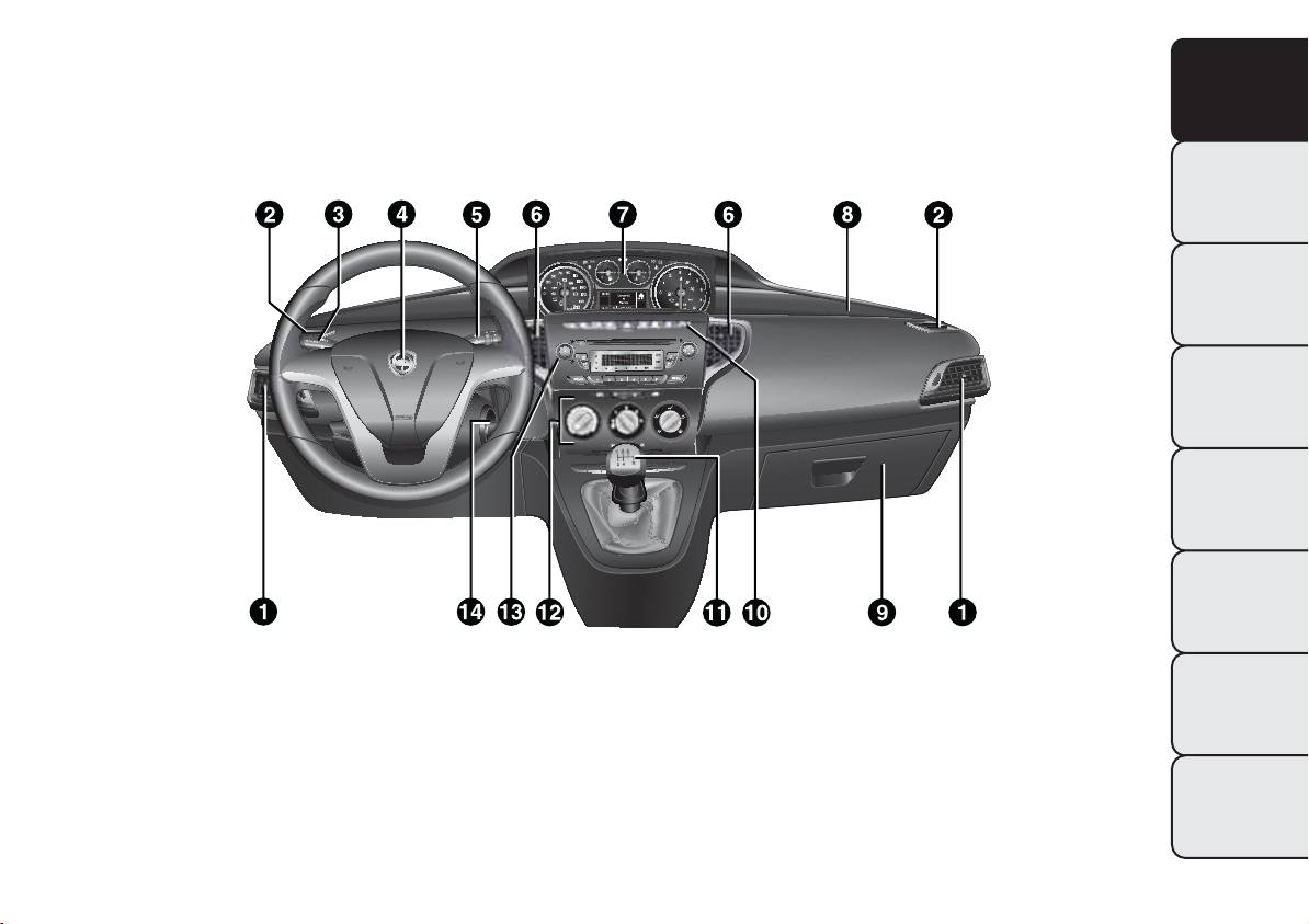
GETTING TO KNOW YOUR CAR
DASHBOARD
The presence and position of the controls, instruments and indicators may vary according to the
different versions.
fig. 1
1. Adjustable air diffusers 2. Fixed diffusers for directing air to the side windows 3. Exterior light control lever
4. Driver's front air bag 5. Windscreen wiper/rear window wiper/trip computer control lever 6. Adjustable centre
air diffusers 7. Instrument panel 8. Passenger's front air bag 9. Glove compartment 10. Control buttons 11. Gear
lever 12. Heating/ventilation/climate control system controls 13. Sound system (for versions/markets, where
provided) 14. Ignition device
L0F0092
GETTING TO
KNOW YOUR CAR
SAFETY
STARTING AND
DRIVING
WARNING LIGHTS
AND MESSAGES
IN AN EMERGENCY
SERVICING AND
MAINTENANCE
TECHNICAL
SPECIFICATIONS
INDEX
3
Page 8

GETTING TO
KNOW YOUR CAR
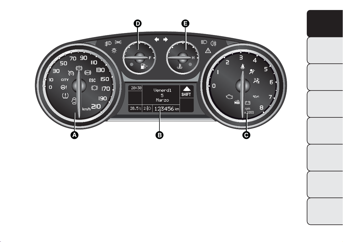
CONTROL PANEL AND
INSTRUMENTS
Instrument background colour and type may vary according to the version.
The warning lights
SAFETY
scale for the rev counter is 6000 rpm
VERSIONS WITH MULTIFUNCTION DISPLAY
STARTING AND
DRIVING
WARNING LIGHTS
AND MESSAGES
IN AN EMERGENCY
SERVICING AND
MAINTENANCE
TECHNICAL
SPECIFICATIONS
fig. 2
A. Speedometer (speed indicator) B. Multifunction display C. Rev counter D. Fuel level gauge with reserve warning
light E. Engine coolant temperature gauge with overheating warning light
INDEX
, and are only present on Diesel versions. On diesel versions, the end of
L0F0002
4
Page 9
VERSIONS WITH RECONFIGURABLE MULTIFUNCTIONAL DISPLAY
GETTING TO
KNOW YOUR CAR
SAFETY
STARTING AND
DRIVING
WARNING LIGHTS
AND MESSAGES
IN AN EMERGENCY
fig. 3
A. Speedometer (speed indicator) B. Reconfigurable multifunction display C. Rev counter D. Fuel level gauge with
reserve warning light E. Engine coolant temperature gauge with overheating warning light
L0F0001
SERVICING AND
MAINTENANCE
TECHNICAL
SPECIFICATIONS
INDEX
5
Page 10
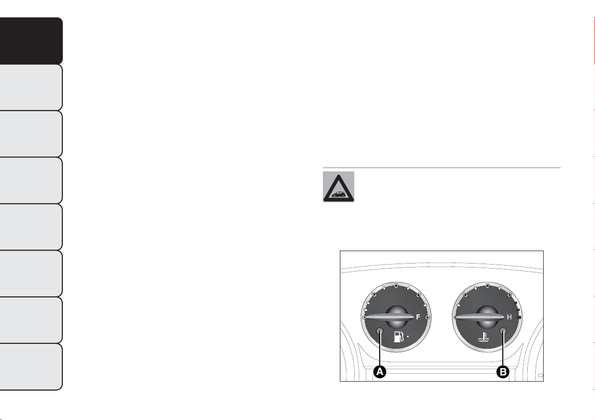
SPEEDOMETER (SPEED INDICATOR)
GETTING TO
Shows the car speed (speedometer).
KNOW YOUR CAR
REV COUNTER
This indicates the engine rpm.
SAFETY
FUEL LEVEL GAUGE
This shows the amount of fuel left in the fuel tank.
STARTING AND
DRIVING
E - tank empty
F - tank full
The warning light A fig. 4 (on certain versions
WARNING LIGHTS
AND MESSAGES
together with the message on the display) switches
on to indicate that approximately 5 to 7 litres of
fuel are left in the tank; in this event refuel at the
earliest opportunity.
IN AN EMERGENCY
Do not travel with the fuel tank almost empty: the
gaps in fuel delivery could damage the catalyst.
IMPORTANT The needle will point to E and
SERVICING AND
MAINTENANCE
warning light A will flash to indicate a fault in the
system. Go to a Lancia Dealership to have the
system checked.
ENGINE COOLANT TEMPERATURE
INDICATOR
This gauge indicates the temperature of the engine
coolant.
C - Low engine coolant temperature.
H - High engine coolant temperature.
The warning light B fig. 4 may switch on (with a
message on the display for some versions) to
indicate that the coolant temperature is too high;
in this case, stop the engine and contact a Lancia
Dealership.
If the needle reaches the red area, stop
the engine immediately and contact a
Lancia Dealership.
TECHNICAL
SPECIFICATIONS
INDEX
6
fig. 4
L0F0026
Page 11
DISPLAY
The car may be provided with a multifunction/
reconfigurable multifunction display that shows
useful information, according to the previous
settings, when driving.
With the ignition key removed, the display
activates and shows the time and total milometer
reading (in km or miles) for a few seconds when
a door is opened/closed.
NOTE With a low outside temperature (below
0°C) it may take longer than normal for
information to appear on the display.
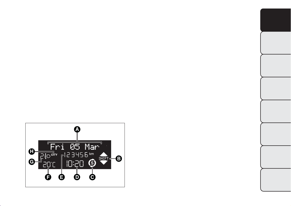
MULTIFUNCTION DISPLAY "STANDARD"
SCREEN
The following information is shown on the display
fig. 5 :
Date
A
Gear Shift Indicator (for versions/markets,
B
where provided)
Start&Stop function indication (for versions/
C
markets, where provided)
Time (always displayed, even with key removed
D
and doors closed)
Milometer (display of distance travelled in
E
kilometres/miles)
Outside temperature (for versions/markets
F
where provided)
Headlamp alignment position (only with dipped
G
headlights on)
Activation of Dualdrive electric power steering
H
(CITY indication) or of ECO driving mode
(ECO indication)
GETTING TO
KNOW YOUR CAR
SAFETY
STARTING AND
DRIVING
WARNING LIGHTS
AND MESSAGES
IN AN EMERGENCY
SERVICING AND
MAINTENANCE
fig. 5
TECHNICAL
SPECIFICATIONS
INDEX
L0F1008
7
Page 12
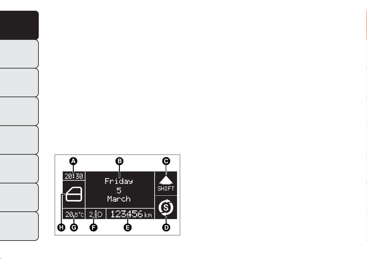
RECONFIGURABLE MULTIFUNCTION
GETTING TO
KNOW YOUR CAR
DISPLAY "STANDARD" SCREEN
The following information is shown on the display
fig. 6 :
Time
A
SAFETY
Date or trip distance display in kilometres (or
B
miles)
Gear Shift Indicator (for versions/markets,
C
STARTING AND
DRIVING
where provided)
Start&Stop function indication (for versions/
D
markets, where provided)
Milometer (display of distance travelled in
E
WARNING LIGHTS
kilometres/miles)
AND MESSAGES
IN AN EMERGENCY
SERVICING AND
MAINTENANCE
Headlamp alignment position (only with dipped
F
headlights on)
Outside temperature (for versions/markets
G
where provided)
Car status indications (e.g. doors open, possible
H
ice on road, etc.)
On some versions the display shows the turbine
pressure.
TECHNICAL
SPECIFICATIONS
INDEX
8
fig. 6
L0F1007
Page 13
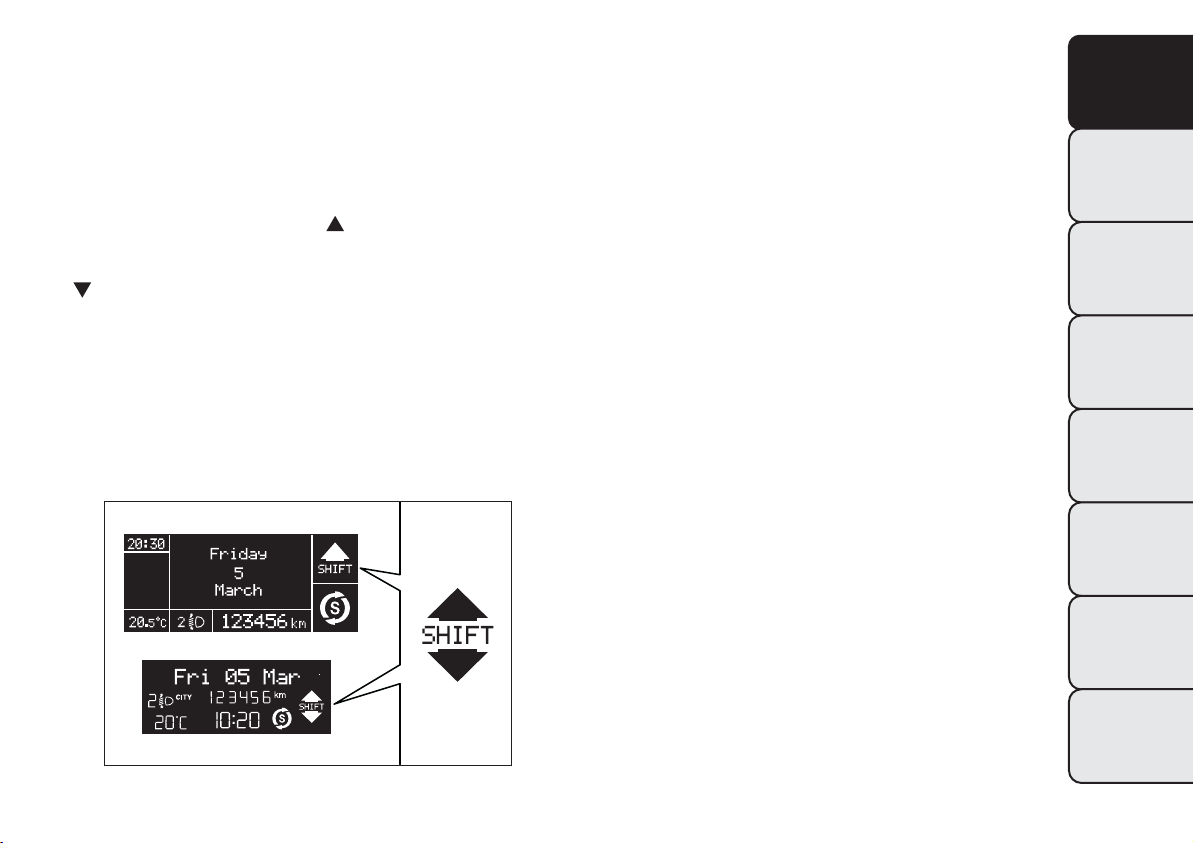
GEAR SHIFT INDICATOR
The GSI (Gear Shift Indicator) system advises the
driver to change gear through a specific indication
on the control panel fig. 7.
Through the GSI, the driver is notified that
changing gear will allow a reduction in fuel
consumption.
When the SHIFT UP icon (
SHIFT) is shown on
the display, the GSI is advising the driver to
engage a higher gear, while the SHIFT DOWN
(
SHIFT) icon advises the driver to engage a
lower gear.
The indication in the instrument panel remains on
until the driver changes gear or the driving
conditions return to a situation where changing
gear is not required to improve consumption.
WELCOME MOVEMENT
On some versions, when the key is turned to MAR,
the following occurs:
❒ quick movement (up and down) of the
speedometer and rpm gauge
❒ lighting of graphic symbols/display
❒ display of the Lancia logo.
Gauge movement
If the key is removed from the ignition switch
whilst the gauges are moving, they immediately
return to their initial position.
Once they have reached the full scale values, the
gauges rest on the value indicated by the car.
The movement of the gauges stops when the
engine is started.
GETTING TO
KNOW YOUR CAR
SAFETY
STARTING AND
DRIVING
WARNING LIGHTS
AND MESSAGES
IN AN EMERGENCY
SERVICING AND
MAINTENANCE
fig. 7
TECHNICAL
SPECIFICATIONS
INDEX
L0F1010
9
Page 14
Lighting of graphic symbols/display
GETTING TO
KNOW YOUR CAR
A few seconds after the key is inserted, the gauges,
graphic symbols and display light up in sequence.
Lancia logo display
SAFETY
When the key is removed from the ignition switch
(with the doors closed), the display remains lit
and shows the Lancia logo. The display lighting is
STARTING AND
DRIVING
then dimmed gradually until it switches off
completely.
CONTROL BUTTONS
WARNING LIGHTS
AND MESSAGES
NOTA Buttons
the following pages.
On versions equipped with gas discharge
headlights (Xenon) the buttons are
IN AN EMERGENCY
To scroll up through the screen and the related
options or to increase the displayed value.
and fig. 8 are described in
and .
Buttons
and activate different functions
according to the following situations:
❒ within the menu, they allow you to scroll up and
down;
❒ during setting operations, they increase or
decrease values.
SERVICING AND
MAINTENANCE
Press briefly to access the menu and/or go to next
screen or confirm the desired menu selection.
Hold down to go back to the standard screen.
TECHNICAL
SPECIFICATIONS
To scroll down through the displayed menu and
the related options or to decrease the displayed
value.
INDEX
10
fig. 8
L0F0042
Page 15

SETUP MENU
The menu comprises a series of options which can
be selected using buttons
the different selection and setting operations
(Setup) indicated below. Some options have a
submenu.
The menu can be activated by briefly pressing the
button.
The menu comprises the following options:
❒ MENU
❒ LIGHTING
❒ SPEED BEEP
❒ LIGHT SENSOR (for versions/markets, where
provided)
❒ RAIN SENSOR (for versions/markets, where
provided)
❒ TRIP B ACTIVATION/DATA
❒ SET TIME
❒ SET DATE
❒ FIRST PAGE (for versions/markets, where
provided)
❒ AUTOCLOSE
❒ MEASUREMENT UNIT
❒ LANGUAGE
❒ BUZZER VOLUME
❒ BUTTON VOLUME
❒ BELT BUZZER
and to access
❒ SERVICE
❒ AIRBAG/PASSENGER BAG (for versions/
markets, where provided)
❒ EXIT MENU
Selecting an option from the main menu without a
submenu:
❒ briefly press the
menu option to be set;
❒ press buttons
select the new setting;
❒ briefly press the
setting and to go back to the main menu option
selected previously.
Selecting an option from the main menu with a
submenu:
❒ a short press on the
first submenu option;
❒ press buttons
scroll through all the submenu options;
❒ briefly press the
submenu option and to open the relevant set-up
menu;
❒ press buttons
select the new setting for this submenu option;
❒ Briefly press button
and at the same time go back to the previously
selected menu option.
button to select the main
or (with single presses) to
button to store the new
button will display the
or (with single presses) to
button to select the displayed
or (with single presses) to
to store the new setting
GETTING TO
KNOW YOUR CAR
SAFETY
STARTING AND
DRIVING
WARNING LIGHTS
AND MESSAGES
IN AN EMERGENCY
SERVICING AND
MAINTENANCE
TECHNICAL
SPECIFICATIONS
INDEX
11
Page 16

MENU ITEMS
GETTING TO
KNOW YOUR CAR
SAFETY
STARTING AND
DRIVING
WARNING LIGHTS
AND MESSAGES
IN AN EMERGENCY
SERVICING AND
MAINTENANCE
TECHNICAL
SPECIFICATIONS
Menu
This item allows you to access the Setup Menu.
Press the
Menu items. Hold down the
the standard screen.
Lighting (Interior light adjustment) (with side
lights on only)
With the side lights on, this function is used to set
the brightness of the instrument panel, radio
controls and automatic climate control system
controls (for versions/markets where provided) to
8 levels.
Proceed as follows to adjust the brightness:
briefly press button
flash on the display;
press button
level;
briefly press button
or hold the button down to return to the standard
screen without saving.
or button to select the various
button to return to
, the previously set level will
or to adjust the brightness
to return to the menu screen
Speed Beep (Speed limit)
This function is used to set the car speed limit
(km/h or mph); the driver is immediately alerted
when this limit is exceeded.
To set the desired speed limit, proceed as follows:
❒ briefly press button
wording "Speed Beep";
❒ press button
activation (On) or deactivation (Off);
❒ if the function is on, press
the required speed limit and then press
confirm.
Note Setting is possible between 30 and 200
km/h, or 20 and 125 mph, according to the
previously set unit. See the "Measurement unit
adjustment (Measurement unit)" paragraph
described below. The setting will increase/decrease
by five units each time button
pressed. Hold down the
automatically increase/decrease the setting
rapidly. Complete the setting by briefly pressing
the button when you approach the required value.
❒ press the
screen or hold the button down to return to the
standard screen without storing.
button briefly to return to the menu
: the display will show the
or to select speed limit
or to select
to
/ is
/ button to
INDEX
12
Page 17

To cancel the setting, proceed as follows:
❒ briefly press the
the display;
❒ press button
display;
❒ press the
screen or give the button a long press to return
to the standard screen without storing.
Headlight sensor (automatic headlights/dusk
sensor sensitivity adjustment) (for versions/
markets, where provided)
This function is used to turn the headlights on or
off according to external light conditions.
The dusk sensor sensitivity can be adjusted
according to 3 levels (level 1 = minimum
sensitivity, level 2 = average sensitivity, level 3 =
maximum sensitivity); the greater the sensitivity
set, the less the external light variation needed
to turn on the lights (e.g. with a setting on level 3
at sunset the headlights switch on earlier in
relation to levels 1 and 2).
Proceed as follows to set:
❒ press the
level will flash on the display;
❒ press the
adjustment;
❒ press the
screen or give the button a long press to return
to the standard screen without storing.
button briefly to return to the menu
button briefly; the previously set
button briefly to return to the menu
button: "On" will flash on
: "Off" will flash on the
or button to make the
Rain sensor (Rain sensor sensitivity
adjustment)(for versions/markets, where
provided)
This function allows you to adjust the rain sensor
sensitivity to 4 levels.
To set the required sensitivity level, proceed as
follows:
❒ briefly press the
sensitivity “level” flashes on the display;
❒ press the
adjustment;
❒ press the
screen or give the button a long press to return
to the standard screen without storing.
button briefly to return to the menu
button: the previously set
or button to make the
GETTING TO
KNOW YOUR CAR
SAFETY
STARTING AND
DRIVING
WARNING LIGHTS
AND MESSAGES
IN AN EMERGENCY
SERVICING AND
MAINTENANCE
TECHNICAL
SPECIFICATIONS
INDEX
13
Page 18

Activation/Trip B data (Activating Trip B)
GETTING TO
KNOW YOUR CAR
SAFETY
STARTING AND
DRIVING
WARNING LIGHTS
AND MESSAGES
IN AN EMERGENCY
SERVICING AND
MAINTENANCE
TECHNICAL
SPECIFICATIONS
With this function it is possible to activate ("On")
or deactivate ("Off") the Trip B display (trip
meter). For more information see the "Trip
computer" paragraph.
For activation/deactivation, proceed as follows:
❒ press the
flash On or Off according to the previous
setting;
❒ press the
adjustment;
❒ press the
screen or give the button a long press to return
to the standard screen without storing.
Time adjustment (Clock adjustment)
This function enables the clock to be set through
two submenus: “Time” and “Format”.
To carry out the adjustment, proceed as follows:
❒ briefly press the button
the two submenus "Time" and "Format";
❒ press the button
the two submenus;
❒ once you have selected the submenu to be
changed, press the button
❒ when you select “Time”, pressing
makes the "hours" flash on the display; press
the
INDEX
button briefly to make the display
or button to make the
button briefly to return to the menu
: the display will show
or to switch between
briefly;
briefly
or button to make the adjustment;
❒ briefly press the
display flash the "minutes"; press the
button to make the adjustment;
❒ if you select the "Format" submenu, pressing
the
button briefly makes the display mode
flash on the display. Press the
to select "12h" or "24h" mode. When you
have carried out the required settings, briefly
press the
screen or hold the button down to go back
to the main menu screen without storing the
new settings.
Hold down the
standard screen or to the main menu according to
where you are in the menu.
IMPORTANT The setting will increase or decrease
by one unit each time the button
pressed. Keeping the button pressed causes an
automatic rapid speed increase/decrease.
Complete the setting by briefly pressing the button
when you approach the required value.
button to go back to the submenu
button, which makes the
or
or button
button again to return to the
or is
14
Page 19

Set date (Setting the date)
Using this function it is possible to update the date
(year - month - day).
To carry out the adjustment, proceed as follows:
❒ briefly press the
the display;
❒ press the
adjustment;
❒ briefly press
display;
❒ press the
adjustment;
❒ briefly press the
the display;
❒ press the
adjustment;
❒ press the
screen or give the button a long press to return
to the standard screen without storing.
IMPORTANT The setting will increase or decrease
by one unit each time the button
pressed. Keeping the button pressed causes an
automatic rapid speed increase/decrease.
Complete the setting by briefly pressing the button
when you approach the required value.
button briefly to return to the menu
button: the year will flash on
or button to make the
: the “month” will flash on the
or button to make the
button: the day will flash on
or button to make the
or is
First page (display of information on the main
screen)(for versions/markets, where provided)
This function allows you to choose the information
you would like to display on the main screen.
You can view the date or the trip distance.
To carry out the adjustment, proceed as follows:
❒ briefly press the
appear on the display;
❒ press the
"Date" and "Trip distance" options;
❒ briefly press
display;
❒ press
wish to see on the main page of the display;
❒ press the
screen or give the button a long press to return
to the standard screen without storing.
When the key is turned to MAR and the initial
check stage is over, the display will show the
information selected via the "First page" menu
function.
button again briefly to display the
or to select the information you
button briefly to return to the menu
button: "First page" will
: the "Month" will flash on the
GETTING TO
KNOW YOUR CAR
SAFETY
STARTING AND
DRIVING
WARNING LIGHTS
AND MESSAGES
IN AN EMERGENCY
SERVICING AND
MAINTENANCE
TECHNICAL
SPECIFICATIONS
INDEX
15
Page 20

Autoclose (automatic central locking with the
GETTING TO
KNOW YOUR CAR
SAFETY
STARTING AND
DRIVING
WARNING LIGHTS
AND MESSAGES
IN AN EMERGENCY
SERVICING AND
MAINTENANCE
car in motion)
When activated (On), this function locks the doors
automatically when the vehicle speed exceeds 20
km/h.
Proceed as follows to activate or deactivate this
function:
❒ press the
flash On or Off according to what was
previously set;
❒ press
❒ press the
submenu screen or hold the button down to
return to the main menu screen without saving;
❒ hold the
the standard screen or to the main menu
according to where you are in the menu.
button briefly to make the display
or to make your choice;
button briefly to return to the
button down again to return to
Unit of measurement (Setting the unit of
measurement)
With this function it is possible to set the units
through three submenus: "Distances",
"Consumption" and "Temperature".
To set the desired measurement unit, proceed as
follows:
❒ briefly press
❒ press button
three submenus;
❒ once you have selected the submenu to be
changed, press the button
❒ when you select “Distances”, briefly pressing
the button
or "mi" depending on the previous setting;
❒ press
❒ when you select “Consumption”, pressing
button
"mpg" appear on the display depending on
the previous setting;
to display the three submenus;
or to navigate through the
briefly;
makes the display show "km"
or to select;
briefly makes "km/l", "l/100km" or
TECHNICAL
SPECIFICATIONS
INDEX
16
Page 21

If the set distance unit is "km", the fuel
consumption unit will be displayed in km/l or
l/100 km. If the distance unit of measurement
stored is "mi," the display shows the amount of
fuel consumed in "mpg".
❒ press
❒ when you select “Temperature”, pressing the
button
on the display depending on the previous
setting;
❒ press
Once the required settings are made, briefly press
button
hold the button down to return to the main menu
screen without storing.
Hold down the
standard screen or to the main menu according to
where you are in the menu.
or to make your choice;
briefly makes "°C" or "°F" appear
or to make your choice;
to go back to the submenu screen or
button again to return to the
Language (Language selection)
Display messages can be shown in the following
languages: Italian, English, German, Portuguese,
Spanish, French, Dutch, Polish. Turkish and
Brazilian.
To set the desired language, proceed as follows:
❒ briefly press the button
language starts flashing on the display;
❒ press
❒ press the
screen or give the button a long press to return
to the standard screen without storing.
or to make your choice;
button briefly to return to the menu
: the previously set
GETTING TO
KNOW YOUR CAR
SAFETY
STARTING AND
DRIVING
WARNING LIGHTS
AND MESSAGES
IN AN EMERGENCY
SERVICING AND
MAINTENANCE
TECHNICAL
SPECIFICATIONS
INDEX
17
Page 22

Warnings volume (Adjusting the alert/warning
GETTING TO
KNOW YOUR CAR
SAFETY
STARTING AND
DRIVING
WARNING LIGHTS
AND MESSAGES
IN AN EMERGENCY
SERVICING AND
MAINTENANCE
acoustic signal volume)
With this function the volume of the buzzer which
accompanies the display of any failure/warning
can be adjusted according to 8 levels.
To set the desired volume, proceed as follows:
❒ press the
flash the previously set volume level;
❒ press
❒ press the
screen or give the button a long press to return
to the standard screen without storing.
button briefly, making the display
or to make your choice;
button briefly to return to the menu
Button volume (Adjusting the button volume)
With this function it is possible to adjust (to eight
levels) the volume of the acoustic signal emitted
when the
and return to the standard menu
To set the desired volume, proceed as follows:
❒ press the
flash the previously set volume level;
❒ press the button
volume; an acoustic signal equal to the volume
level being selected is emitted during this
adjustment;
❒ press the
screen or give the button a long press to return
to the standard screen without storing.
On versions with reconfigurable multifunction
display, the volume level is represented by bars.
button is held down to exit a submenu
button briefly, making the display
or to adjust the
button briefly to return to the menu
TECHNICAL
SPECIFICATIONS
INDEX
18
Page 23

Belt buzzer (Buzzer activation for SBR
indication) (for versions/markets, where
provided)
This function can only be displayed after a Lancia
Dealership has deactivated the SBR system (see
"SBR system" in the "Safety" chapter).
Service (Scheduled servicing)
Using this function you can display information
about the mileage or daily intervals for car
servicing. With the Service function it is also
possible to view the interval (in kilometres or
miles) before the next engine oil change is due.
To consult this display, proceed as follows:
❒ briefly press the
display show the service interval in kilometres
(km) or miles (mi) according to the previous
setting (see "Distance units of measurement"
paragraph);
❒ briefly press button
screen or hold it down to return to the standard
screen.
button, which makes the
to return to the menu
Note The "Scheduled Servicing Plan" requires the
car to be serviced every 30,000 km (or 18,000
miles). This is automatically displayed, when the
ignition key is turned to MAR, from 2,000 km
(or the equivalent in miles) and reappears every
200 km (or the equivalent in miles). Below 200
km servicing indications are more frequent. The
display will be in kilometres or miles depending
on the measurement unit settings. When the next
scheduled service is approaching, the message
"Service" will appear on the display, followed by
the number of kilometres or miles left, when
the key is turned to MAR. Contact a Lancia
Dealership where the operations of the "Scheduled
Servicing Plan" will be performed and the
message will be reset.
GETTING TO
KNOW YOUR CAR
SAFETY
STARTING AND
DRIVING
WARNING LIGHTS
AND MESSAGES
IN AN EMERGENCY
SERVICING AND
MAINTENANCE
TECHNICAL
SPECIFICATIONS
INDEX
19
Page 24

Airbag/Passenger bag
GETTING TO
KNOW YOUR CAR
SAFETY
STARTING AND
DRIVING
WARNING LIGHTS
AND MESSAGES
IN AN EMERGENCY
SERVICING AND
MAINTENANCE
(Activation/deactivation of passenger side
front airbag and side bag for chest/pelvis
protection - for versions/markets, where
provided)
This function allows the passenger airbag to be
activated / deactivated.
Proceed as follows:
❒ press the
pass: Off" (to deactivate) or "Bag pass: On" (to
activate) is displayed by pressing buttons
❒ a confirmation request message will appear on
the display;
❒ by pressing the
(to confirm activation/deactivation) or "No"
(to cancel);
❒ press the
the selection is displayed and you return to the
menu screen; Hold down the button to return to
the standard screen without storing.
button and, after the message "Bag
and , press the button again;
or buttons select "Yes"
button briefly; a message confirming
Exit Menu
This function closes the cycle of settings listed in
the menu screen. Pressing the
return the display to the standard screen without
storing. Press button
menu item (Speed Beep).
to return to the first
button briefly will
TECHNICAL
SPECIFICATIONS
INDEX
20
Page 25

TRIP COMPUTER
General information
The Trip computer is used to display information
on car operation when the key is turned to
MAR-ON. This function allows you to define two
separate trips, called “Trip A” and “Trip B”,
for monitoring the car's "complete mission"
(journey) in a reciprocally independent manner.
Both functions are resettable (reset - start of a new
journey).
“Trip A” is used to display the figures relating to:
❒ Outside temperature (for LPG/Natural Power
versions equipped with multifunction display)
❒ Range
❒ Distance travelled
❒ Average consumption
❒ Instantaneous consumption
❒ Average speed
❒ Trip time (driving time).
“Trip B” may be used to display the figures
relating to:
❒ Distance travelled B
❒ Average consumption B
❒ Average speed B
❒ Trip time B (driving time).
Note “Trip B” may be disabled (see “Activating
Trip B”). “Range” and “Instantaneous fuel
consumption" parameters cannot be reset.
GETTING TO
KNOW YOUR CAR
SAFETY
STARTING AND
DRIVING
WARNING LIGHTS
AND MESSAGES
IN AN EMERGENCY
SERVICING AND
MAINTENANCE
TECHNICAL
SPECIFICATIONS
INDEX
21
Page 26

Values displayed
GETTING TO
KNOW YOUR CAR
SAFETY
STARTING AND
DRIVING
WARNING LIGHTS
AND MESSAGES
IN AN EMERGENCY
SERVICING AND
MAINTENANCE
Range
This indicates the approximate distance which can
be travelled with the amount of fuel present in
the tank. “----”will appear on the display in the
following cases:
❒ range value lower than 50 km (or 30 mi)
❒ car parked with engine running for a long
period.
IMPORTANT The range value variation can be
affected by several factors: driving style, type
of route (motorway, towns and cities, mountain
roads, etc.), conditions of use (load, tyre pressures,
etc.). Trip planning must therefore take the above
into account.
Distance travelled
Shows the distance covered since the start of the
new journey.
Average consumption
Shows the approximate average fuel consumption
since the start of the new journey.
Instantaneous consumption
This value shows the fuel consumption. The value
is constantly updated. The display will show “- -
- -” if the car is parked with the engine running.
Average speed
This shows the car average speed as a function of
the overall time elapsed since the start of the
new mission.
Trip time
Shows the time elapsed since the start of a new
journey.
TECHNICAL
SPECIFICATIONS
INDEX
22
Page 27

Indications on display
Each time a value is displayed, the following
information is shown fig. 9:
❒ A - animated icon in the upper part;
❒ B - name, value and unit of measure of the
selected parameter (e.g. "Range 150 km");
❒ C - the word "Trip" (or "Trip A" or "Trip B").
After a few seconds the name and value of the
selected parameter are replaced by an icon fig. 10.
The icons relating to the various parameters are
the following:
❒
❒
"Range";
"Average consumption A” (if Trip A is
active, or “B” if Trip B is active);
❒
"Distance" (if Trip A is active, or
“B” if Trip B is active);
❒
❒
"Instantaneous consumption";
"Average speed A” (if Trip A is active, or
“B” if Trip B is active);
❒
"Trip time" (if Trip A is active, or “B” if
Trip B is active);
GETTING TO
KNOW YOUR CAR
SAFETY
STARTING AND
DRIVING
WARNING LIGHTS
AND MESSAGES
IN AN EMERGENCY
SERVICING AND
MAINTENANCE
fig. 9
L0F1009
fig. 10
TECHNICAL
SPECIFICATIONS
INDEX
L0F0032
23
Page 28

TRIP BUTTON
GETTING TO
KNOW YOUR CAR
This is located on the right-hand stalk fig. 11.
With the ignition key turned to MAR, this button
allows you to view the previously described
parameters and also reset them to begin a new
SAFETY
mission:
❒ short press: display various readings;
❒ long press: reset readings and start a new
STARTING AND
mission.
DRIVING
WARNING LIGHTS
AND MESSAGES
IN AN EMERGENCY
SERVICING AND
MAINTENANCE
New mission
This begins after a reset:
❒ “manual” resetting by the user, by pressing the
relevant button;
❒ "automatic" resetting, when the "Trip distance"
reaches 99999.9 km or when the "Travel time"
reaches 999:59 (999 hours and 59 minutes);
❒ after disconnection/reconnection of the battery.
IMPORTANT The reset operation when “Trip
A” or “Trip B” details are being displayed resets
the information associated with the function
displayed.
Start of journey procedure
With ignition key at MAR, press and hold the
TRIP button for more than 2 seconds to reset.
TECHNICAL
SPECIFICATIONS
INDEX
24
fig. 11
L0F0079
Page 29

Exit Trip
You can automatically exit the TRIP function once
all the values have been displayed or by holding
the button
down for more than 1 second.
SYMBOLS
Some car components have coloured labels whose
symbols indicate precautions to be observed
when using this component. Under the bonnet
there is also a label that summarises all the
symbols.
GETTING TO
KNOW YOUR CAR
SAFETY
STARTING AND
DRIVING
WARNING LIGHTS
AND MESSAGES
IN AN EMERGENCY
SERVICING AND
MAINTENANCE
TECHNICAL
SPECIFICATIONS
INDEX
25
Page 30

THE LANCIA CODE SYSTEM
GETTING TO
KNOW YOUR CAR
SAFETY
STARTING AND
DRIVING
WARNING LIGHTS
AND MESSAGES
IN AN EMERGENCY
SERVICING AND
MAINTENANCE
To further protect your car from theft, it has been
fitted with an engine immobilising system. It is
automatically activated when the ignition key
is removed.
Each key contains an electronic device which
modulates the signal emitted during ignition by an
antenna built into the ignition device. The signal
is the "password", different every time the car
is started, through which the control unit
recognises the key and enables starting.
OPERATION
Each time the car is started by turning the ignition
key to MAR, the Lancia CODE system control
unit sends an acknowledgement code to the engine
control unit to deactivate the immobilizer. The
code is sent only if the control unit of the Lancia
CODE system has acknowledged the code received
from the key.
Each time the ignition key is turned to STOP, the
Lancia CODE system deactivates the functions
of the engine management control unit. If, during
starting, the code is not correctly recognised, the
warning light switches on in the instrument
panel. In this case, turn the key to STOP and then
to MAR; if it is still locked, try again with the
other keys that come with the vehicle. Contact a
Lancia Dealership if you still cannot start the
engine.
Warning light
If the
that the system is running a self-diagnosis (for
example for a voltage drop). If the problem
persists, contact a Lancia Dealership.
warning light switches on, this means
switching on while driving
TECHNICAL
SPECIFICATIONS
INDEX
26
Page 31

THE KEYS
KEY WITHOUT REMOTE CONTROL
The metal insert A fig. 12 enables:
❒ the ignition switch;
❒ the door locks;
❒ the fuel cap lock/release (for versions/markets,
where provided).
To request duplicates of the key, go to a Lancia
Dealership, taking an ID document and the car
ownership documents.
KEY WITH REMOTE CONTROL
(for versions/markets, where provided)
The metal insert A of the key fig. 13 operates:
❒ the ignition switch;
❒ the door locks;
❒ the fuel cap lock/release (for versions/markets,
where provided).
Press button B to open/close the metal insert.
GETTING TO
KNOW YOUR CAR
SAFETY
STARTING AND
DRIVING
WARNING LIGHTS
AND MESSAGES
IN AN EMERGENCY
SERVICING AND
MAINTENANCE
fig. 12
L0F0077
fig. 13
TECHNICAL
SPECIFICATIONS
INDEX
L0F0075
27
Page 32

Unlocking the doors and the tailgate
GETTING TO
KNOW YOUR CAR
SAFETY
STARTING AND
DRIVING
WARNING LIGHTS
AND MESSAGES
IN AN EMERGENCY
SERVICING AND
MAINTENANCE
TECHNICAL
SPECIFICATIONS
Briefly press button
luggage compartment, timed switching-on of
internal roof lights and double flashing of
direction indicators (for versions/markets, where
provided).
The doors are unlocked automatically if the fuel
cut-off system intervenes.
Once the doors are locked, if one or more doors or
the boot are not closed correctly, the LED and
direction indicators start flashing quickly.
Locking the doors and the tailgate
Briefly press button
luggage compartment, with switching-off of roof
light and single flashing of direction indicators
(for versions/markets, where provided).
If one or more doors are open, the doors will not
be locked. This is indicated by a rapid flashing of
the direction indicators (for versions/markets,
where provided). The doors are locked if the
luggage compartment is open
When a speed of over 20 km/h is reached, the
doors are automatically locked if this specific
function has been set (only on versions with
multi-function reconfigurable display).
: for unlocking of doors and
: for locking of doors and
When the doors are locked from outside the car
(using the remote control), A LED above the
button will switch on for a few seconds and
then start flashing (deterrent function).
When the doors are locked from inside the car (by
pressing the
constantly.
Opening the luggage compartment
Press the
compartment using the remote control.
The direction indicators will flash twice to indicate
that the luggage compartment has been opened.
The electronic components inside the
key may be damaged if the key is
subjected to strong shocks. In order to
ensure complete efficiency of the electronic
devices inside the key, it should never be
exposed to direct sunlight.
button) the LED will remain on
button to open the luggage
INDEX
28
Page 33

REQUEST FOR ADDITIONAL REMOTE
CONTROLS
The system can recognise up to 8 remote controls.
Should a new remote control be necessary, go to
a Lancia Dealership, taking an ID document
and the car ownership documents.
REPLACING THE BATTERY IN THE KEY
WITH REMOTE CONTROL
To replace the battery, proceed as follows:
❒ press button A fig. 14 and open the metal insert
B;
❒ turn the screw C to
using a fine bit
screwdriver;
❒ take out the battery case D and replace the
battery E making sure that polarities are
correct;
❒ refit the battery case D inside the key and lock
it turning the screw C to
.
Used batteries should be disposed of,
as specified by law, in special
containers, otherwise take them to a
Lancia Dealership, which will deal with their
disposal.
GETTING TO
KNOW YOUR CAR
SAFETY
STARTING AND
DRIVING
WARNING LIGHTS
AND MESSAGES
IN AN EMERGENCY
SERVICING AND
MAINTENANCE
fig. 14
TECHNICAL
SPECIFICATIONS
INDEX
L0F0189
29
Page 34

SAFE LOCK DEVICE
GETTING TO
KNOW YOUR CAR
(for versions/markets, where provided)
This safety device inhibits the operation of the
interior door handles and the door locking/
unlocking button. We recommend that you
SAFETY
activate this device each time you park your car.
Activating the device
STARTING AND
DRIVING
The device is enabled on all the doors by quickly
double-pressing the
The direction indicators flash 3 times and the
LED above the
WARNING LIGHTS
AND MESSAGES
indicate that the device has been activated. The
device does not come on if one or more doors
is not properly shut.
IN AN EMERGENCY
SERVICING AND
MAINTENANCE
button on the key.
fig. 15 button flashes to
Deactivating the device
The device deactivates automatically:
❒ by pressing the
button on the remote control;
❒ by turning the ignition key to the MAR position.
WARNING
Once the safe lock system is engaged,
it is impossible to open the doors
from inside the car. Therefore, before getting
out of the car check that there is no-one
left on board.
TECHNICAL
SPECIFICATIONS
INDEX
30
fig. 15
L0F0081
Page 35

IGNITION DEVICE
The key can be turned to 3 different
positionsfig. 16:
❒ STOP: engine off, key can be removed, steering
column locked. Some electrical devices (e.g.
sound system, central door locking system, etc.)
can operate;
❒ MAR: driving position. All electrical devices are
enabled;
❒ AVV: engine start-up.
The ignition switch is fitted with a safety system
that requires the ignition key to be turned back to
STOP if the engine does not start, before the
starting operation can be repeated.
WARNING
If the ignition device has been
tampered with (e.g. an attempted
theft), have it checked over by a Lancia
Dealership before driving again.
WARNING
Always remove the key when you
leave your car to prevent someone
from accidentally operating the controls.
Remember to engage the handbrake. Engage
st
1
gear if the car is parked uphill or reverse
if the car is parked downhill. Never leave
children unattended in the car.
GETTING TO
KNOW YOUR CAR
SAFETY
STARTING AND
DRIVING
WARNING LIGHTS
AND MESSAGES
fig. 16
L0F0102
STEERING LOCK
Engagement: when the key is in position STOP,
remove the key and turn the steering wheel until it
is locked.
Disengagement: move the steering wheel slightly
as you turn the ignition key to MAR.
IN AN EMERGENCY
SERVICING AND
MAINTENANCE
TECHNICAL
SPECIFICATIONS
INDEX
31
Page 36

GETTING TO
KNOW YOUR CAR
steering system or steering column
modifications (e.g.: installation of anti-theft
SAFETY
device) that could badly affect performance
and safety, invalidate the warranty and
also result in non-compliance of the car
with type-approval requirements.
STARTING AND
DRIVING
WARNING LIGHTS
AND MESSAGES
as soon as it is turned. This holds true for
cars being towed as well.
IN AN EMERGENCY
SERVICING AND
MAINTENANCE
WARNING
It is absolutely forbidden to carry out
any after-market operation involving
WARNING
Never remove the key while the car is
moving. The steering wheel will lock
SEATS
WARNING
All adjustments must be made with
the car stationary.
FRONT SEATS
Lengthwise adjustment
Lift the lever A fig. 17 and push the seat forwards
or backwards: in driving position your arms
should rest on the rim of the steering wheel.
TECHNICAL
SPECIFICATIONS
INDEX
32
fig. 17
L0F0062
Page 37

WARNING
Once you have released the
adjustment lever, always check that
the seat is locked on the guides by trying to
move it back and forth. If the seat is not
locked into place, it may unexpectedly slide
and cause the driver to lose control of the
car.
Height adjustment
(for versions/markets, where provided)
Move lever B fig. 18 upwards or downwards to
achieve the required height.
IMPORTANT Carry out the adjustment while
sitting on the seat involved (driver side or
passenger side).
Backrest angle adjustment
Adjust knob C fig. 19 to obtain the required
position.
GETTING TO
KNOW YOUR CAR
SAFETY
STARTING AND
DRIVING
WARNING LIGHTS
AND MESSAGES
IN AN EMERGENCY
SERVICING AND
MAINTENANCE
fig. 18
L0F0063
fig. 19
TECHNICAL
SPECIFICATIONS
INDEX
L0F0064
33
Page 38

Lumbar adjustment
GETTING TO
KNOW YOUR CAR
(for versions/markets, where provided)
The position of the back against the seat backrest
can be adjusted by turning knob D fig. 20.
SAFETY
STARTING AND
DRIVING
WARNING LIGHTS
AND MESSAGES
IN AN EMERGENCY
SERVICING AND
MAINTENANCE
Electric seat heating
(for versions/markets, where provided)
With the ignition key turned to MAR, press
buttons E fig. 21 to switch the function on/off.
When the function is activated, the LED on the
buttons will light up.
IMPORTANT If this function is activated with
engine off the battery will run down.
TECHNICAL
SPECIFICATIONS
INDEX
34
fig. 20
L0F0273
fig. 21
L0F0247
Page 39

HEAD RESTRAINTS
FRONT
They are height-adjustable: to adjust them,
operate as follows.
Upwards adjustment: raise the head restraint
until it clicks into place.
Downwards adjustment: press button A fig. 22
and lower the head restraint.
"Anti-Whiplash" Device
The head restraints are equipped with an
“Anti-Whiplash” device, which reduces the
distance between head and head restraint in the
event of a rear impact, thus mitigating the
"whiplash" effect.
The head restraint may move when the backrest is
pressed by the occupant's torso or hand: this
behaviour is caused by the system and should not
be considered a malfunction.
WARNING
All adjustments must be made with
the car stationary. Head restraints
must be adjusted so that the head, rather
than the neck, rests on them. Only when they
are adjusted in this manner can they serve
their intended purpose.
WARNING
To make the best use of the head
restraint's protective action, adjust
the backrest so that you are sitting upright
and keep your head as close as possible
to the head restraint.
REAR
(for versions/markets, where provided)
Two height-adjustable head restraints are
provided for the rear seats. On some versions a
head restraint is also provided for the central seat.
Upwards adjustment: raise the head restraint
until it clicks into place.
GETTING TO
KNOW YOUR CAR
SAFETY
STARTING AND
DRIVING
WARNING LIGHTS
AND MESSAGES
IN AN EMERGENCY
SERVICING AND
MAINTENANCE
TECHNICAL
SPECIFICATIONS
INDEX
fig. 22
L0F0061
35
Page 40

Downwards adjustment: press button A fig. 23
GETTING TO
KNOW YOUR CAR
and lower the head restraint.
Proceed as follows to remove the head restraints:
❒ raise the head restraints to their maximum
height;
SAFETY
❒ press buttons A and B fig. 23 at the side of the
two supports, then remove the head restraints
by pulling them upwards.
STARTING AND
DRIVING
IMPORTANT If the rear seats are used, always set
the head restraints in the "completely raised"
position.
WARNING LIGHTS
AND MESSAGES
IN AN EMERGENCY
SERVICING AND
MAINTENANCE
STEERING WHEEL
The steering wheel can be adjusted vertically.
To adjust, move lever A fig. 24 downwards to
position 1, then adjust the steering wheel to the
most suitable position and lock it in position
by moving lever A to position 2.
WARNING
All adjustments must be carried out
only with the car stationary and
engine off.
TECHNICAL
SPECIFICATIONS
INDEX
36
A
fig. 23
B
L0F0201
fig. 24
L0F0078
Page 41

WARNING
It is absolutely forbidden to carry out
any after-market operation involving
steering system or steering column
modifications (e.g. installation of anti-theft
device) that could badly affect performance
and safety, invalidate the warranty and
also result in the car not meeting typeapproval requirements.
REAR VIEW MIRRORS
INTERIOR MIRROR
The mirror is fitted with a safety device that
causes its release in the event of a violent impact
with the passenger.
Operate lever A fig. 25 to adjust the mirror into
two different positions: normal or anti-glare.
GETTING TO
KNOW YOUR CAR
SAFETY
STARTING AND
DRIVING
WARNING LIGHTS
AND MESSAGES
IN AN EMERGENCY
SERVICING AND
MAINTENANCE
fig. 25
TECHNICAL
SPECIFICATIONS
INDEX
L0F0054
37
Page 42

DOOR MIRRORS
GETTING TO
KNOW YOUR CAR
Manual adjustment
From the inside of the car, operate lever A fig. 26
to adjust the mirror.
SAFETY
STARTING AND
DRIVING
WARNING LIGHTS
AND MESSAGES
IN AN EMERGENCY
SERVICING AND
MAINTENANCE
Electrical adjustment
(for versions/markets, where provided)
The mirrors can be adjusted only if the ignition
key is in MAR position.
To adjust proceed as follows:
❒ use switch A fig. 27 to select the mirror (left or
right) to be adjusted;
❒ to adjust the mirror move the switch B in the
four directions.
TECHNICAL
SPECIFICATIONS
INDEX
38
fig. 26
L0F0053
fig. 27
B
A
L0F0190
Page 43

Manual folding
If necessary, fold the mirrors by moving them
from position 1 (open) to position 2 (closed)
fig. 28.
IMPORTANT When driving the mirrors should
always be in position 1 (open).
CLIMATE CONTROL
SIDE AIR DIFFUSERS
A fig. 29 - Adjustable and directable side air
diffusers:
❒ use device B to adjust the vent to the required
position;
❒ turn wheel C to adjust the air flow.
D - Fixed side air diffuser.
GETTING TO
KNOW YOUR CAR
SAFETY
STARTING AND
DRIVING
WARNING LIGHTS
AND MESSAGES
IN AN EMERGENCY
SERVICING AND
MAINTENANCE
fig. 28
L0F0220
fig. 29
TECHNICAL
SPECIFICATIONS
INDEX
L0F0103
39
Page 44

CENTRAL AIR DIFFUSERS
GETTING TO
KNOW YOUR CAR
A fig. 30 - Adjustable and directable central air
diffusers:
❒ use device B to adjust the vent to the required
position;
SAFETY
❒ turn wheel C to adjust the air flow.
STARTING AND
DRIVING
WARNING LIGHTS
AND MESSAGES
IN AN EMERGENCY
SERVICING AND
MAINTENANCE
TECHNICAL
SPECIFICATIONS
INDEX
40
fig. 30
L0F0104
Page 45

CLIMATIC COMFORT
DIFFUSERS
GETTING TO
KNOW YOUR CAR
SAFETY
STARTING AND
DRIVING
WARNING LIGHTS
AND MESSAGES
IN AN EMERGENCY
SERVICING AND
MAINTENANCE
fig. 31
1. Upper fixed diffusers – 2. Adjustable side diffusers – 3. Fixed diffusers for side windows – 4. Adjustable centre air
diffusers – 5. Passenger compartment front foot area diffusers
L0F0230
TECHNICAL
SPECIFICATIONS
INDEX
41
Page 46

MANUAL CLIMATE CONTROL
GETTING TO
KNOW YOUR CAR
SAFETY
STARTING AND
DRIVING
WARNING LIGHTS
AND MESSAGES
IN AN EMERGENCY
SERVICING AND
MAINTENANCE
TECHNICAL
SPECIFICATIONS
(for versions/markets, where provided)
CONTROLS
A Air temperature knob (red = hot/blue = cold)
B Air recirculation knob
INDEX
fig. 32
internal air recirculation
air intake from outside
L0F0101
IMPORTANT It is advisable to switch the air
recirculation on whilst queueing or in tunnels to
prevent the introduction of polluted air. However,
it is better not to use the function for long periods,
particularly if there are many people on board,
to prevent the windows from misting.
42
Page 47

C Air distribution knob
toward the body and the side windows
toward the body, the side windows and the
feet
toward the feet only
toward the feet and the windscreen
toward the windscreen only
D Heated rear window activation/deactivation
button.
When the function is active, the LED on the
button is lit up.
In order to maintain battery efficiency, the
function is automatically deactivated after about
20 minutes.
E Fan speed adjustment knob.
Note To stop the air flow from the vents turn the
knob to 0.
F climate control compressor on/off button. Press
the button to activate the climate control
system; the LED on the button switches on
contemporarily (this enables rapid cooling of
the passenger compartment).
GETTING TO
KNOW YOUR CAR
SAFETY
STARTING AND
DRIVING
WARNING LIGHTS
AND MESSAGES
IN AN EMERGENCY
SERVICING AND
MAINTENANCE
TECHNICAL
SPECIFICATIONS
INDEX
43
Page 48

Fast windscreen and front side window
GETTING TO
KNOW YOUR CAR
demisting/defrosting (MAX-DEF)
Proceed as follows:
❒ turn knob A to the red section;
❒ move slider B to
SAFETY
❒ turn knob C to
❒ turn knob E to 4 (maximum fan speed).
STARTING AND
DRIVING
IMPORTANT The climate control system is very
useful for speeding up demisting since it
dehumidifies the air. Adjust the controls as
described above and press button
WARNING LIGHTS
AND MESSAGES
climate control system (the LED on the button
will light up).
IN AN EMERGENCY
SERVICING AND
MAINTENANCE
ADDITIONAL HEATER
(for versions/markets, where provided)
This device speeds up passenger compartment
warming when it is very cold. The additional
;
;
heater turns off automatically after reaching the
required comfort conditions.
The heater activates automatically when knob A is
turned to the last red section and the fan is
activated (knob E turned to at least 1
st
speed).
The heater only works if the outside temperature
and engine coolant temperature are low. The
to activate the
heater will not activate if the battery voltage is too
low.
SYSTEM MAINTENANCE
In winter, the climate control system must be
turned on at least once a month for about
10 minutes. Have the system inspected at a
Lancia Dealership before the summer.
TECHNICAL
SPECIFICATIONS
INDEX
44
Page 49

AUTOMATIC CLIMATE CONTROL
(for versions/markets, where provided)
CONTROLS
fig. 33
Buttons A - Manual air distribution selection
By pressing the buttons, one of the five possible
air flow distribution modes can be selected:
to the windscreen and front side window
diffusers to demist or defrost them.
L0F0129
to the central and side dashboard vents to
ventilate the chest and the face during the hot
season.
GETTING TO
KNOW YOUR CAR
SAFETY
STARTING AND
DRIVING
WARNING LIGHTS
AND MESSAGES
IN AN EMERGENCY
SERVICING AND
MAINTENANCE
TECHNICAL
SPECIFICATIONS
INDEX
45
Page 50

GETTING TO
KNOW YOUR CAR
SAFETY
STARTING AND
DRIVING
WARNING LIGHTS
AND MESSAGES
IN AN EMERGENCY
SERVICING AND
MAINTENANCE
TECHNICAL
SPECIFICATIONS
Button B MAX
activation
When the MAX button
activates all the functions required for fast
demisting/defrosting, that is:
❒ compressor on (if the weather conditions are
suitable)
❒ air recirculation off
❒ maximum air temperature setting (HI)
❒ fan speed determined according to the coolant
temperature
❒ air flow conveyed to the windscreen and front
side windows
towards the front seat feet area diffusers. Due
to the natural tendency of heat to rise, this
type of distribution warms the passenger
compartment up as quickly as possible,
providing an immediate feeling of warmth.
distribution between feet area diffusers
+
(warmest air) and dashboard vents
(coolest air).
distribution between feet area diffusers
+
and windscreen/front side window
diffusers. This type of distribution
achieves effective heating of the
passenger compartment and prevents
the windows from misting up.
- MAX-DEF function
is pressed, the system
❒ Button C
activation/deactivation
When the
button C to switch off the compressor.
When the compressor is deactivated:
❒ the system will deactivate air recirculation to
prevent the windows from misting up;
❒ it is not possible to convey air to the passenger
compartment with a temperature below the
outside temperature (the temperature indicated
on the display will flash when the system cannot
guarantee the required comfort conditions);
❒ the fan speed can be manually reset (with
compressor enabled, ventilation cannot go
below a bar shown on the display).
- Climate control compressor
symbol is lit on the display, press
INDEX
46
Page 51

Button D - Internal air recirculation
on/off
It is advisable to switch the internal air
recirculation on whilst queuing or in tunnels to
prevent the introduction of polluted air.
At low temperatures or if the compressor is off,
the recirculation is forced to off to prevent
misting.
IMPORTANT It is inadvisable to use air
recirculation when the outside temperature is low,
since the windows could mist rapidly.
Button E (AUTO) - AUTO function activation
(automatic climate control operation)
When the AUTO button is pressed and the
required temperature is set, the system adjusts air
temperature, quantity and distribution into the
passenger compartment and manages the
activation of the compressor.
Button F
deactivation
When button
switches on.
- Heated rear window activation/
is pressed, the LED on the button
Buttons G
Button H (OFF) - Climate control activation/
deactivation
When the OFF button is pressed, the system is
deactivated.
With the system off, the climate control system
conditions are as follows:
❒ all LEDs are off;
❒ set temperature display is off;
❒ air recirculation is off;
❒ compressor is off;
❒ fan is off.
Button I - Air temperature increase
When the button is pressed, the passenger
compartment air temperature increases.
Button L - Air temperature decrease
When the button is pressed, the passenger
compartment air temperature decreases.
- Fan speed adjustment
GETTING TO
KNOW YOUR CAR
SAFETY
STARTING AND
DRIVING
WARNING LIGHTS
AND MESSAGES
IN AN EMERGENCY
SERVICING AND
MAINTENANCE
TECHNICAL
SPECIFICATIONS
INDEX
47
Page 52

DESCRIPTION
GETTING TO
KNOW YOUR CAR
SAFETY
STARTING AND
DRIVING
WARNING LIGHTS
AND MESSAGES
IN AN EMERGENCY
SERVICING AND
MAINTENANCE
TECHNICAL
SPECIFICATIONS
The automatically controlled parameters and
functions are:
❒ air temperature at the vents;
❒ air distribution at the vents;
❒ fan speed (continuous variation of the air flow)
❒ compressor activation (for cooling/
dehumidifying the air)
❒ air recirculation.
All functions may be changed manually. In other
words, you may select one or more functions
and change the parameters as required. Automatic
control of the manually changed functions will
be suspended: the system will only override your
settings for safety-related reasons (e.g. risk of
misting).
Manual selections always have higher priority over
automatic settings and are stored until the user
switches the system back to automatic control
expect for cases in which the system intervenes for
particular safety-related reasons. You can adjust
one function manually without affecting the
automatic control of the others.
The amount of air introduced into the passenger
compartment is not affected by car speed; it is
regulated by the fan, which is controlled
electronically.
The temperature of the air introduced is always
controlled automatically, according to the
temperature set in the display for the driver and
the front passenger (except when the system is off
or in certain conditions when the compressor is
deactivated).
The system allows the following to be set or
adjusted manually:
❒ air temperature;
❒ fan speed (continuous variation)
❒ air distribution with 5 positions;
❒ compressor activation
❒ single zone/dual zone distribution priority
❒ rapid defrosting/demisting function
❒ air recirculation
❒ heated rear window
❒ system deactivation.
INDEX
48
Page 53

SWITCHING ON THE CLIMATE CONTROL
SYSTEM
The system can be switched on in various ways; it
is however advisable to press the AUTO button
and set the desired temperature on the display.
The climate control system allows you to
customise the temperatures requested.
The climate control system compressor works only
with the engine running and with an outside
temperature of above 0°C.
AUTOMATIC CLIMATE CONTROL SYSTEM
OPERATION
Press the AUTO button; the system will
automatically adjust:
❒ the amount of air introduced into the passenger
compartment;
❒ the distribution of the air in the passenger
compartment;
cancelling all previous manual adjustments.
During climate control system automatic
operation, the word AUTO appears on the display.
During automatic operation it is still possible to
adjust the temperatures set and carry out the
following operations manually:
❒ fan speed adjustment
❒ air distribution selection
❒ internal air recirculation on/off button;
❒ climate control compressor activation.
WARNING
It is advisable not to use the internal
air recirculation function when the
outside temperature is low, because the
windows could mist rapidly.
ADJUSTING THE FAN SPEED
Press button
The possible speeds are indicated by bars lighting
up on the display:
❒ maximum fan speed = all bars lit
❒ minimum fan speed = one bar lit.
The fan can be disabled (no bars lit) only if the
climate control compressor has been switched off
by pressing button
To restore automatic fan speed control after a
manual adjustment, press the AUTO button.
to increase/decrease the fan speed.
.
GETTING TO
KNOW YOUR CAR
SAFETY
STARTING AND
DRIVING
WARNING LIGHTS
AND MESSAGES
IN AN EMERGENCY
SERVICING AND
MAINTENANCE
TECHNICAL
SPECIFICATIONS
INDEX
49
Page 54

RAPID FRONT WINDOW DEMISTING/
GETTING TO
KNOW YOUR CAR
SAFETY
STARTING AND
DRIVING
WARNING LIGHTS
AND MESSAGES
IN AN EMERGENCY
SERVICING AND
MAINTENANCE
TECHNICAL
SPECIFICATIONS
DEFROSTING (MAX-DEF function)
Press button MAX
the timed operation of all the functions required to
rapidly demist/defrost the windscreen and front
side windows.
The functions are:
❒ climate control compressor activation (with an
outside temperature of above 0°C);
❒ deactivation, if previously activated, of the
internal air recirculation
❒ activation of heated rear window (LED on
button MAX
coils
❒ setting maximum air temperature
❒ activation of air flow.
DEMISTING/DEFROSTING OF HEATED
REAR WINDOW AND DOOR MIRRORS
Press button
activated, the button LED switches on.
This function is timed and will deactivate
automatically after 20 minutes. Press button
again to switch the function off in advance.
IMPORTANT Do not apply stickers on the inside
of the rear window over the heating filaments
to avoid damage.
INDEX
IMPORTANT To draw in air from outside, press
button
to automatically activate
on) and door mirror heater
to activate: when this function is
.
INTERNAL AIR RECIRCULATION
ACTIVATION
Press button
Air recirculation is carried out according to two
possible operating modes:
❒ forced deactivation (air recirculation always
deactivated, air taken from the outside)
❒ forced activation (internal air circulation always
activated).
When the OFF button is pressed, the climate
control system automatically activates internal air
recirculation. External air recirculation can always
be activated by pressing button
versa.
Automatic recirculation operation is requested by
pressing the AUTO button.
.
and vice
50
Page 55

IMPORTANT Internal air recirculation makes it
possible to reach the required heating or cooling
conditions more quickly depending on the mode
selected. It is not advisable to switch the air
recirculation on when it is rainy/cold to prevent
the windows from misting, especially if the climate
control system has not been activated. It is
advisable to switch the internal air recirculation
on whilst queuing or in tunnels to prevent the
introduction of polluted air. Do not use the
function for a long time, particularly if there are
several passengers on board, to prevent the
windows from misting.
CLIMATE CONTROL COMPRESSOR
ACTIVATION/DEACTIVATION
Press button
compressor.
Compressor activation:
display.
Compressor deactivation
symbol on display disappears;
❒
❒ internal air recirculation excluded;
With the climate control compressor switched off,
air cannot be introduced into the passenger
compartment that has a lower temperature than
the outside air; in this case the
display will flash.
The deactivation of the climate control compressor
is memorised even after the engine has stopped.
To reactivate the climate control compressor, press
button
the other manual settings will be cancelled.
to switch on the climate control
symbol appears on
symbol in the
or AUTO again: if you press AUTO,
AIR DISTRIBUTION SELECTION
Press one or more of buttons A to manually select
one of the possible air distribution settings for
the passenger compartment:
Air flow to the windscreen and front side
window diffusers to demist/defrost them.
Air flow to the footwell diffusers. This air
distribution allows the passenger
compartment to be warmed up quickly.
Air flow distribution to centre/side dashboard
diffusers (passenger's body).
Air flow distributed between footwell
+
diffusers and windscreen and front side
window defrosting/demisting diffusers.
This distribution setting allows the
passenger compartment to be warmed
effectively and prevents the windows
from misting.
Air flow distribution between footwell
+
diffusers (hotter air) and centre/side
dashboard diffusers (cooler air).
IMPORTANT For the climate control system to
function, at least one of the buttons A must be
operated. The system does not allow the
deactivation of all the buttons A.
IMPORTANT Push the OFF button to turn the
climate control system back on: in this way, all
operating conditions memorised before switching
off are restored.
To restore automatic control of the air distribution
after a manual selection, press the AUTO button.
GETTING TO
KNOW YOUR CAR
SAFETY
STARTING AND
DRIVING
WARNING LIGHTS
AND MESSAGES
IN AN EMERGENCY
SERVICING AND
MAINTENANCE
TECHNICAL
SPECIFICATIONS
INDEX
51
Page 56

SWITCHING OFF THE CLIMATE CONTROL
GETTING TO
KNOW YOUR CAR
SAFETY
STARTING AND
DRIVING
WARNING LIGHTS
AND MESSAGES
SYSTEM
Press the OFF button.
The following information is shown on the
display:
❒ OFF
❒ internal air recirculation active indication.
SYSTEM MAINTENANCE
In winter, the climate control system must be
turned on at least once a month for about
10 minutes.
Before summer, have the system checked at a
Lancia Dealership.
ADDITIONAL HEATER
(for versions/markets, where provided)
This allows the passenger compartment to be
heated more quickly in cold weather conditions.
The heater switches on automatically according to
the environmental conditions and with engine
started when the temperature of the engine
coolant is low.
The heater switches off automatically when the
required comfort conditions are achieved.
The heater only operates if the outside
temperature and engine coolant temperature are
low. The heater will not activate if the battery
voltage is too low.
IN AN EMERGENCY
SERVICING AND
MAINTENANCE
TECHNICAL
SPECIFICATIONS
leakage. Never use R12 fluid, which is not
compatible with the system components.
INDEX
52
The system uses R134a refrigerant
fluid which does not pollute the
environment in the event of accidental
Page 57

START&STOP
Automatic Climate Control
The automatic climate control manages the
Start&Stop function (engine off when the car
speed is zero) to guarantee adequate comfort
inside the passenger compartment.
In particular, when the weather is extremely hot,
the Start&Stop function is deactivated until
adequate passenger compartment comfort is
ensured. During these transitory stages the engine
is not stopped, even if the car speed is zero.
When the Start&Stop function is active (engine off
at zero car speed), the climate control system will
request the reactivation of the engine if the inside
temperature conditions rapidly deteriorate (or if
the user requests maximum cooling – LO – or
quick demisting – MAX DEF).
With Start&Stop function active (engine off at
zero car speed), the air flow rate (if managed
automatically) is reduced in order to maintain the
passenger compartment comfort conditions for
as long as possible.
The climate control system control unit attempts
to manage the decreased comfort caused by
stopping the engine as far as possible (switching
off the compressor and engine coolant pump) but
the operation of the climate control system can
be favoured by deactivating the Start&Stop
function using the dedicated button on the
dashboard.
NOTE In particularly severe climate conditions it
is recommended to limit the use of the Start&Stop
function to prevent the compressor from
continuously switching on and off, with
consequent rapid misting of the windows and
accumulation of humidity with unpleasant smells
in the passenger compartment.
GETTING TO
KNOW YOUR CAR
SAFETY
STARTING AND
DRIVING
WARNING LIGHTS
AND MESSAGES
IN AN EMERGENCY
SERVICING AND
MAINTENANCE
TECHNICAL
SPECIFICATIONS
INDEX
53
Page 58

GETTING TO
KNOW YOUR CAR
SAFETY
EXTERNAL LIGHTS
The left-hand stalk operates most of the external
lights.
The ignition key has to be in the MAR position for
the exterior lights to come on.
The instrument panel and the various dashboard
controls will come on with the external lights.
WARNING
The daytime running lights are an
alternative to the dipped beam
headlights for driving during the daytime in
countries where it is compulsory to have
lights on during the day, and they are also
permitted in those countries where this not
obligatory.
STARTING AND
DRIVING
DAY LIGHTS (DRL)
"Daytime Running Lights"
(for versions/markets, where provided)
WARNING LIGHTS
AND MESSAGES
With the ignition key turned to MAR-ON and ring
nut A fig. 34 turned to position O the daytime
running lights are automatically activated; the
other lights and interior lighting remain off.
IN AN EMERGENCY
SERVICING AND
MAINTENANCE
TECHNICAL
SPECIFICATIONS
INDEX
54
fig. 34
WARNING
Daytime running lights cannot
replace dipped headlights when
driving at night or through tunnels. The use
of daytime running lights is governed by
the highway code of the country in which
you are driving. Comply with legal
requirements.
L0F0127
Page 59

SIDE LIGHTS AND DIPPED BEAM
HEADLIGHTS
With the ignition key turned to MAR, turn the ring
nut A fig. 34 to
activated, the daytime running lights go out and
the side lights and dipped headlights come on.
The
instrument panel.
When the ignition key is turned to STOP or
removed and the ring nut A is turned from O to
come on. The
instrument panel.
PARKING LIGHTS
These lights can only be switched on with ignition
key at STOP or removed, by moving ring nut A
first to position O and then to position
The warning light
instrument panel. When the direction indicator
stalk is activated the side for the lights (left or
right) can be selected.
warning light will come on in the
, all the side lights and number plate lights
. If dipped beams are
warning light switches on in the
.
switches on on the
AUTOMATIC LIGHTING CONTROL
(AUTOLIGHT) (Dusk sensor)
where provided)
This infrared LED sensor, combined with the rain
sensor and located on the windscreen, detects
the variations in outside brightness depending on
the light sensitivity set with the Setup Menu:
the greater the sensitivity, the less external light is
required to activate the exterior lights.
Activation
The dusk sensor activates when ring nut A fig. 34
is turned to
dipped headlights are activated automatically
according to the external light level.
When the lights are turned on by the sensor, the
fog lights (for versions/markets, where provided)
and the rear fog lights may be turned on. When
the lights are automatically switched off, the front
and rear fog lights (if activated) are also switched
off. The next time the lights are switched on
automatically, the fog lights must be reactivated
manually (if required).
With the sensor active, it is possible to flash the
headlights but the main beam headlights cannot
be switched on. To activate these lights, turn
the ring nut A to
beam headlights.
. In this way the side lights and
and activate the fixed dipped
(for versions/markets,
GETTING TO
KNOW YOUR CAR
SAFETY
STARTING AND
DRIVING
WARNING LIGHTS
AND MESSAGES
IN AN EMERGENCY
SERVICING AND
MAINTENANCE
TECHNICAL
SPECIFICATIONS
INDEX
55
Page 60

When the lights have been activated automatically
GETTING TO
KNOW YOUR CAR
SAFETY
STARTING AND
DRIVING
WARNING LIGHTS
AND MESSAGES
IN AN EMERGENCY
SERVICING AND
MAINTENANCE
TECHNICAL
SPECIFICATIONS
and are then switched off by the sensor, the
dipped beam headlights are switched off first,
followed by the side lights a few seconds later. If
the sensor is activated but is malfunctioning,
the side lights and dipped beam headlights are
switched on irrespective of the outside light level
and the sensor failure is indicated on the
instrument panel display. It is also possible to
deactivate the sensor and switch on the side lights
and dipped beam headlights.
IMPORTANT The sensor is unable to detect the
presence of fog. Under these circumstances, these
lights are therefore turned on manually.
MAIN BEAM HEADLIGHTS
To activate the main beam headlights, with ring
nut at
wheel. The warning light
instrument panel.
When the stalk is pulled towards the steering
wheel again, the lights deactivate, the dipped
headlights reactivate and the
switches off.
It is not possible to switch on the main beam
headlights in fixed mode if the automatic lighting
control system is active.
, pull the stalk towards the steering
switches on in the
warning light
FLASHING
You can flash the headlights by pulling the stalk
towards the wheel (unstable position). The
warning light will come on in the instrument
panel.
DIRECTION INDICATORS
Bring the stalk to the (stable) position:
upwards: right-hand direction indicator
activation;
downwards: left-hand direction indicator
activation.
Warning light
instrument panel. The indicators switch off
automatically when the steering wheel is
straightened.
Lane change function
If you wish to signal a lane change, put the left
stalk in the unstable position for less than half a
second.
The direction indicator on the side selected will be
activated for 5 flashes and then go out
automatically.
or should flash in the
INDEX
56
Page 61

“FOLLOW ME HOME” DEVICE
This allows the space in front of the car to be lit
up for a certain period of time.
Activation: with the ignition key on STOP or
removed, pull the stalk towards the steering wheel
within 2 minutes from when the engine is turned
off.
At each single movement of the stalk, the lights
will remain on for an extra 30 seconds up to a
maximum of 210 seconds; then the lights are
switched off automatically.
Each time the stalk is operated, the
light on the instrument panel switches on and the
display also shows a message and how long the
function will remain active.
warning
The
is first moved and stays on until the function is
automatically deactivated. Each movement of the
stalk only increases the amount of time the lights
stay on.
Deactivation: keep the stalk pulled towards the
steering wheel for more than two seconds.
warning light switches on when the stalk
GETTING TO
KNOW YOUR CAR
SAFETY
STARTING AND
DRIVING
WARNING LIGHTS
AND MESSAGES
IN AN EMERGENCY
SERVICING AND
MAINTENANCE
TECHNICAL
SPECIFICATIONS
INDEX
57
Page 62

WINDOW CLEANING
GETTING TO
KNOW YOUR CAR
SAFETY
STARTING AND
DRIVING
WARNING LIGHTS
AND MESSAGES
IN AN EMERGENCY
SERVICING AND
MAINTENANCE
TECHNICAL
SPECIFICATIONS
The right stalk controls windscreen wiper/washer
and heated rear window wiper/washer operation.
WINDSCREEN WASHER/WIPER
They can be operated only with the ignition key
turned to MAR.
The ring nut A fig. 35 can be moved to four
different positions:
windscreen wiper off.
intermittent operation.
continuous slow operation.
continuous fast operation.
Move the stalk upwards (unstable position) to
limit operation to the time for which the stalk is
held in this position. When released, the stalk will
return to its default position and the wiper will
be automatically stopped.
With the ring nut A fig. 35 in position
, the
windscreen wiper will automatically adapt
operating speed to the speed of the car.
With the windscreen wipers operational, if reverse
gear is engaged, the rear window wiper is
automatically activated.
Never use the windscreen wipers to
remove layers of snow or ice from the
windscreen. In such conditions, the
windscreen wipers may be subjected to
excessive stress and the motor protection,
which prevents operation for a few seconds,
may intervene. If operation is not restored
(even after using the key to restart the engine),
contact a Lancia Dealership.
Do not operate the windscreen wiper
with the blades lifted from the
windscreen.
INDEX
58
fig. 35
L0F0126
Page 63

"Smart washing" function
Pull the lever towards the steering wheel (unstable
position) to activate the windscreen washer.
Keeping the stalk pulled for more than half a
second, with just one movement it is possible to
operate the washer jet and the wiper at the same
time.
The wiper stops working three strokes after the
stalk is released.
A further stroke after approximately six seconds
completes the wiping cycle.
RAIN SENSOR
(for versions/markets, where provided)
This is located behind the interior rear view
mirror, in contact with the windscreen fig. 36 and
can detect the presence of rain and, consequently,
manage the cleaning of the windscreen in
accordance with the amount of water on the
screen.
The sensor has an adjustment range that varies
progressively from wiper still (no stroke) when the
windscreen is dry, to wiper at 2
nd
continuous
speed (fast continuous operation) with intense
rain.
Activation
The sensor is activated when the ring nut A fig. 35
is turned to
position: the windscreen wiper
stroke frequency is thus adjusted in accordance
with the amount of water on the windscreen.
The activation of the sensor is signalled by a
"stroke" to show that the command has been
acquired.
The sensitivity of the rain sensor can be adjusted
through the Setup menu (see paragraph "Menu
Items" in this section).
The increasing of the rain sensor sensitivity is also
signalled by a stroke of the wipers.
IMPORTANT Keep the glass in the sensor area
clean.
If the windscreen washer is used with the rain
sensor activated, the normal washing cycle is
performed, after which the rain sensor resumes its
normal automatic operation.
fig. 36
L0F0188
GETTING TO
KNOW YOUR CAR
SAFETY
STARTING AND
DRIVING
WARNING LIGHTS
AND MESSAGES
IN AN EMERGENCY
SERVICING AND
MAINTENANCE
TECHNICAL
SPECIFICATIONS
INDEX
59
Page 64

Deactivation
GETTING TO
Move the stalk ring nut away from the position
KNOW YOUR CAR
If the ignition key is turned to the STOP position
leaving the ring nut A in position
SAFETY
cycle is performed at the next startup (ignition key
to the MAR position) even if rain is present. This
prevents unwanted activation of the rain sensor
when the engine is started (i.e. when the
STARTING AND
DRIVING
windscreen is being washed by hand or the wipers
are stuck to the windscreen by ice).
To restore automatic operation of the rain sensor,
turn ring nut A from
WARNING LIGHTS
and then turn the ring nut back to the
AND MESSAGES
When the rain sensor is reactivated using any of
the manoeuvres described above, reactivation
IN AN EMERGENCY
is indicated by a single stroke of the windscreen
wipers, regardless of the condition of the
windscreen.
SERVICING AND
MAINTENANCE
or turn the ignition key to STOP.
position to position
position.
, no wiping
If the sensitivity is changed whilst the rain sensor
is operating, a windscreen wiper stroke is carried
out to confirm the change even if the windscreen
is dry.
In the event of malfunction of the rain sensor
whilst it is active, the windscreen wiper operates
intermittently at a speed consistent with the
sensitivity setting of the rain sensor, regardless of
whether there is rain on the glass (on some
versions sensor failure is indicated on the display).
The sensor continues to operate and it is possible
to set the windscreen wiper to continuous mode
st
(1
or 2ndspeed). The failure indication remains
for as long as the sensor is active.
TECHNICAL
SPECIFICATIONS
INDEX
60
Page 65

The rain sensor is able to recognise, and
automatically adjust itself in the presence of the
following conditions:
❒ presence of dirt on the controlled surface (salt,
dirt, etc.);
❒ presence of streaks of water caused by the worn
window wiper blades;
❒ difference between day and night.
Do not activate the rain sensor when
washing the car in an automatic car
wash.
Make sure the device is switched off if
there is ice on the windscreen.
WARNING
Make sure the device is switched off
whenever the windscreen must be
cleaned.
REAR WINDOW WASHER/ WIPER
It can be operated only with the ignition key
turned to MAR.
Activation
Turn the ring nut B fig. 35 from
the rear window wiper as follows:
❒ in intermittent mode when the windscreen wiper
is not operating;
❒ in synchronous mode (at half the speed of the
windscreen wiper) when the windscreen wiper
is operating;
❒ in continuous mode with reverse gear engaged
and the control active.
With the windscreen wiper on and reverse gear
engaged, rear window wiping will be continuous.
Pushing the stalk towards the dashboard
(unstable position) the rear window washer jet
will activate. Keep the stalk pushed for more than
half a second to activate the rear window wiper
as well. Releasing the stalk will activate the smart
washing function, as described for the windscreen
wiper.
to to operate
GETTING TO
KNOW YOUR CAR
SAFETY
STARTING AND
DRIVING
WARNING LIGHTS
AND MESSAGES
IN AN EMERGENCY
SERVICING AND
MAINTENANCE
TECHNICAL
SPECIFICATIONS
INDEX
61
Page 66

GETTING TO
KNOW YOUR CAR
SAFETY
STARTING AND
DRIVING
Deactivation
The function stops when the stalk is released.
Do not use the rear window wiper to
remove layers of snow or ice. In these
conditions, the windscreen wipers may
be submitted to excessive effort resulting in
the motor protection cutting in and wiper
operation being inhibited for a few seconds. If
operation is not restored, contact a Lancia
Dealership.
CRUISE CONTROL
(for versions/markets, where provided)
This is an electronically controlled driving
assistance device which allows the car to be driven
at a chosen speed above 30 km/h on long
stretches of dry, straight roads with few variations
(e.g. motorways), without having to depress the
accelerator pedal.
The use of this device on extra-urban roads with
traffic is not therefore recommended. Do not
use the device in town.
WARNING LIGHTS
AND MESSAGES
IN AN EMERGENCY
SERVICING AND
MAINTENANCE
TECHNICAL
SPECIFICATIONS
INDEX
62
Activating the device
Turn ring nut A fig. 37 to ON. Activation is
indicated by the
warning light switching on
and, on some versions, by a message on the
display.
fig. 37
L0F0202
Page 67

The speed adjustment function cannot be
activated in 1
activate the function in 4
st
or reverse gear; it is advisable to
th
or higher gears.
When travelling downhill with the device active,
the car speed may slightly exceed the stored one.
Storing car speed
Proceed as follows:
❒ turn ring nut A fig. 37 to ON and press the
accelerator pedal so that the car reaches the
desired speed;
❒ move the stalk upwards (+) for at least one
second, then release it: the speed is memorised
and you can therefore release the accelerator
pedal.
If needed (when overtaking for instance), you can
accelerate simply by depressing the accelerator
pedal: when you release the pedal, the car goes
back to the speed stored previously.
Restoring the stored speed
If the device has been deactivated, for example by
depressing the brake or clutch pedal, the stored
speed can be restored as follows:
❒ accelerate progressively until a speed close to
that stored is reached;
❒ engage the gear selected at the time that the
speed was stored;
❒ press the RES button.
Increasing the stored speed
This can be carried out in two ways:
❒ by pressing the accelerator and storing the new
speed reached
or
❒ by moving the stalk upwards (+).
Each movement of the stalk corresponds to an
increase in speed of about 1 km/h, while keeping
the stalk held upwards will continuously increase
the speed.
GETTING TO
KNOW YOUR CAR
SAFETY
STARTING AND
DRIVING
WARNING LIGHTS
AND MESSAGES
IN AN EMERGENCY
SERVICING AND
MAINTENANCE
TECHNICAL
SPECIFICATIONS
INDEX
63
Page 68

Decreasing the stored speed
GETTING TO
KNOW YOUR CAR
SAFETY
STARTING AND
DRIVING
WARNING LIGHTS
AND MESSAGES
IN AN EMERGENCY
SERVICING AND
MAINTENANCE
TECHNICAL
SPECIFICATIONS
This can be carried out in two ways:
❒ by deactivating the device and then storing the
new speed;
or
❒ by moving the stalk downwards (-) until the
new speed, which will be stored automatically, is
reached.
Each movement of the lever corresponds to a
reduction in speed of about 1 km/h, while keeping
the stalk held downwards will decrease the speed
continuously.
Deactivating the device
The device can be deactivated by the driver in the
following ways:
❒ by turning ring nut A to the OFF position
❒ by stopping the engine
❒ by pressing the brake pedal, the clutch or the
accelerator; in this last case the system is not
effectively deactivated but gives priority to the
acceleration request. The device still remains
active, without the need to press the RES button
to return to the previous condition once
acceleration is concluded.
Automatic deactivation
The device deactivates automatically in the
following cases:
❒ if the ABS or ESC systems intervene
❒ with the car speed below the set limit
❒ in the event of system failure.
WARNING
When travelling with the device
active, never move the gear lever to
neutral.
WARNING
In the event of device faults or
failures, turn knob A to OFF and
contact a Lancia Dealership.
INDEX
64
Page 69

ROOF LIGHTS
FRONT ROOF LIGHT
Switch A fig. 38 switches the roof lights on/off.
A switch positions:
❒ central position (position 1): lights C and D
switch on/off when the doors are opened/closed;
❒ pressed to the left (position 0): lights C and
D are always switched off;
❒ pressed to the right (position 2): lights C and D
are always switched on.
The lights switch on/off gradually.
B switch positions fig. 38:
❒ central position (position 1): lights C and D are
always switched off;
❒ pressed to the left (position 0): light C switches
on;
❒ pressed to the right (position 2): light D
switches on.
IMPORTANT Before getting out of the car, make
sure that both switches are in the central position:
when the doors are closed the lights will switch
off to avoid draining the battery. In any case,
if the switch is left in the on position, the courtesy
light switches off automatically about 15 minutes
after the engine has been switched off.
GETTING TO
KNOW YOUR CAR
SAFETY
STARTING AND
DRIVING
WARNING LIGHTS
AND MESSAGES
fig. 38
L0F0051
Diffused light on dashboard
The diffused light on the dashboard switches on in
the same way as the front roof light.
IN AN EMERGENCY
SERVICING AND
MAINTENANCE
TECHNICAL
SPECIFICATIONS
INDEX
65
Page 70

ROOF LIGHT TIMING
GETTING TO
KNOW YOUR CAR
SAFETY
STARTING AND
DRIVING
WARNING LIGHTS
AND MESSAGES
IN AN EMERGENCY
SERVICING AND
MAINTENANCE
TECHNICAL
SPECIFICATIONS
On certain versions, to facilitate getting into/out of
the car, especially at night or in poorly-lit areas,
two timed modes have been provided.
Timing when getting into the car
The roof lights switch on according to the
following modes:
❒ for about 10 seconds when the doors are
unlocked;
❒ for about 3 minutes when one of the doors is
opened;
❒ for about 10 seconds when the doors are closed.
The timed period is interrupted when the ignition
key is turned to MAR-ON.
The lights switch off in three ways:
❒ when all doors are closed, the 3-minute timer
will stop and a 10-second one will start. This
timer will stop when the key is turned to
MAR-ON;
❒ when doors are locked (either with remote
control or with key on driver side door), the roof
light switches off.
❒ the courtesy lights are switched off in any case
after 15 minutes to preserve battery charge
Timing when getting out of the car
After removing the key from the ignition switch,
the roof lights switch on as follows:
❒ if the ignition key is removed within 3 minutes
from the engine stopping, the roof lights switch
on for 10 seconds;
❒ for about 3 minutes when one of the doors is
opened;
❒ for about 10 seconds when one of the doors is
closed.
The timing stops automatically when the doors are
locked.
INDEX
66
Page 71

REAR ROOF LIGHT
Versions without sun roof
Press the cover A fig. 39 to switch the light on/off.
The light will stay on for a few seconds after the
doors are closed and will then switch off
automatically. The light switches off in any case
when the ignition key is turned to MAR-ON.
The light switches off automatically after a few
minutes if a door is left open. To switch it on
again, open another door or close and reopen the
same door.
Versions with sun roof
In these versions, there are two roof lights A
fig. 40 at the sides (above the rear doors).
Press the point indicated by the arrow to switch
the lights on/off (+ sign on the roof light lens
cover).
The rear roof light(s) also switch on in the same
circumstances that cause the front roof light to
switch on.
GETTING TO
KNOW YOUR CAR
SAFETY
STARTING AND
DRIVING
WARNING LIGHTS
AND MESSAGES
IN AN EMERGENCY
SERVICING AND
MAINTENANCE
fig. 39
L0F0236
fig. 40
TECHNICAL
SPECIFICATIONS
A
INDEX
L0F0227
67
Page 72

LUGGAGE COMPARTMENT ROOF LIGHT
GETTING TO
KNOW YOUR CAR
The roof light A fig. 41 is located on the left side
of the luggage compartment. This switches on
automatically when the luggage compartment is
opened and switches off when it is closed. The
SAFETY
light switches on/off regardless of the ignition key
position.
STARTING AND
DRIVING
WARNING LIGHTS
AND MESSAGES
IN AN EMERGENCY
SERVICING AND
MAINTENANCE
GLOVE COMPARTMENT LIGHT
The roof light A fig. 42 switches on automatically
when the glove compartment is opened and
switches off when it is closed. The light switches
on/off regardless of the ignition key position.
TECHNICAL
SPECIFICATIONS
INDEX
68
fig. 41
L0F0218
fig. 42
L0F0217
Page 73

CONTROLS
HAZARD WARNING LIGHTS
Press button fig. 43 to switch the lights on/off.
When the lights are switched on, the button
flashes and warning lights
instrument panel.
IMPORTANT The use of hazard warning lights is
governed by the highway code of the country
you are driving in: comply with legal
requirements.
and are lit on the
Emergency braking
In the event of emergency braking the hazard
warning lights switch on automatically as well as
warning lights
and in the instrument panel.
The lights switch off automatically when
emergency braking ceases.
GETTING TO
KNOW YOUR CAR
SAFETY
STARTING AND
DRIVING
WARNING LIGHTS
AND MESSAGES
IN AN EMERGENCY
SERVICING AND
MAINTENANCE
fig. 43
TECHNICAL
SPECIFICATIONS
INDEX
L0F0191
69
Page 74

FOG LIGHTS
GETTING TO
KNOW YOUR CAR
(for versions/markets, where provided)
Press button
Press the button again to switch the lights off.
With lights on, the
SAFETY
instrument panel will switch on.
STARTING AND
DRIVING
WARNING LIGHTS
AND MESSAGES
IN AN EMERGENCY
SERVICING AND
MAINTENANCE
fig. 44 to switch the lights on/off.
warning light on the
REAR FOG LIGHT
Press the
fig. 44 button to switch the light
on/off.
The rear fog light switches on only when the
dipped headlights or fog lights are switched on.
Press the button again to switch the light off,
or switch off the dipped headlights or the front fog
lights (for versions/markets, where provided).
With the light on, the
warning light in the
instrument panel switches on.
TECHNICAL
SPECIFICATIONS
INDEX
70
fig. 44
L0F0192
Page 75

CENTRAL LOCKING
Press button
fig. 45 to lock all the doors
simultaneously (the LED on the button will light
up when the doors are locked). Locking takes
place irrespective of the position of the ignition
key.
DUALDRIVE ELECTRIC POWER STEERING
(for versions/markets, where provided)
Press the CITY button fig. 46 to activate the
function. When this function is active, the word
CITY on the instrument panel will light up.
To deactivate the function, press the button again.
For more details, see the "Dualdrive electric
power steering" paragraph in this section.
GETTING TO
KNOW YOUR CAR
SAFETY
STARTING AND
DRIVING
WARNING LIGHTS
AND MESSAGES
IN AN EMERGENCY
SERVICING AND
MAINTENANCE
fig. 45
L0F0081
fig. 46
TECHNICAL
SPECIFICATIONS
INDEX
L0F0043
71
Page 76

ECO FUNCTION
GETTING TO
KNOW YOUR CAR
(for versions/markets, where provided)
Press the ECO button fig. 47 for at least 5 seconds
to activate the function.
When the ECO function is activated, the car is set
SAFETY
for city driving, characterised by less effort on
the steering wheel (Dualdrive system on) and
reduced fuel consumption.
STARTING AND
DRIVING
When this function is activated, the word ECO on
the display will light up on some versions.
This function stays in the memory, so when the
vehicle is started again, the system keeps the
WARNING LIGHTS
AND MESSAGES
setting it had before the engine was stopped. Press
the ECO button again to deactivate the function
and restore the normal driving setting.
IN AN EMERGENCY
SERVICING AND
MAINTENANCE
FUEL CUT-OFF SYSTEM
This intervenes in the event of an impact causing:
❒ the interruption of the fuel supply with the
engine consequently cutting out
❒ the automatic unlocking of the doors
❒ the automatic switching on of the interior lights
❒ the switching on of the hazard warning lights.
On some versions, the intervention of the system is
indicated by a message shown on the display.
IMPORTANT Carefully check the car for fuel
leaks, for instance in the engine compartment,
under the car or near the tank area. After a
collision, turn the ignition key to STOP to prevent
the battery from running down.
TECHNICAL
SPECIFICATIONS
INDEX
72
fig. 47
L0F0039
Page 77

To restore the correct operation of the car, proceed
as follows:
❒ turn the ignition key to the MAR position;
❒ activate the right direction indicator;
❒ deactivate the right direction indicator;
❒ activate the left direction indicator;
❒ deactivate the left direction indicator;
❒ activate the right direction indicator;
❒ deactivate the right direction indicator;
❒ activate the left direction indicator;
❒ deactivate the left direction indicator;
❒ turn the ignition key to the STOP position.
WARNING
If, after an impact, you smell fuel or
notice leaks from the fuel system,
do not reactivate the system to avoid the risk
of fire.
INTERIOR FITTINGS
PASSENGER SIDE GLOVE COMPARTMENT
Operate handle A fig. 48 to open the
compartment. When the compartment is opened a
courtesy light switches on.
WARNING
Never travel with the glove
compartment open: it could injure
the passenger in the event of a crash.
GETTING TO
KNOW YOUR CAR
SAFETY
STARTING AND
DRIVING
WARNING LIGHTS
AND MESSAGES
IN AN EMERGENCY
SERVICING AND
MAINTENANCE
fig. 48
TECHNICAL
SPECIFICATIONS
INDEX
L0F0057
73
Page 78

GETTING TO
KNOW YOUR CAR
SAFETY
POWER SOCKET
It is located on the centralfig. 49 near the
handbrake lever. It only operates with the ignition
key at MAR.
IMPORTANT Do not connect devices with power
higher than 180 W to the socket. Do not damage
the socket by using unsuitable adaptors.
CIGAR LIGHTER
(for versions/markets, where provided)
It is located on the central console next to the
handbrake. Press button A fig. 50 to activate the
cigar lighter.
After a few seconds the button automatically
returns to its initial position, and the cigarette
lighter is ready for use.
STARTING AND
DRIVING
WARNING LIGHTS
AND MESSAGES
IN AN EMERGENCY
SERVICING AND
MAINTENANCE
TECHNICAL
SPECIFICATIONS
INDEX
74
fig. 49
L0F0076
IMPORTANT Always check that the cigar lighter
is switched off.
fig. 50
L0F0258
Page 79

IMPORTANT Do not connect devices with power
higher than 180 W to the socket. Do not damage
the socket by using unsuitable adaptors.
IMPORTANT Do not use the ashtray as a waste
paper basket: it may catch fire in contact with
cigarette stubs.
GETTING TO
KNOW YOUR CAR
WARNING
The cigar lighter gets very hot.
Handle it carefully and make sure
that children don’t use it: risk of fire and/or
burns.
ASHTRAY
(for versions/markets, where provided)
The ashtray is a removable spring-loaded plastic
container that must be fitted into the right
cup/can holder on the central tunnel fig. 51.
SUN VISORS
These are located at the sides of the rear-view
mirror. They can be adjusted forwards and
sideways.
The back of the driver's and passenger side visors
houses two courtesy mirrors. To use the driver's
side mirror, open the sliding cover A fig. 52.
SAFETY
STARTING AND
DRIVING
WARNING LIGHTS
AND MESSAGES
IN AN EMERGENCY
SERVICING AND
MAINTENANCE
TECHNICAL
SPECIFICATIONS
fig. 51
L0F0056
fig. 52
INDEX
L0F0055
75
Page 80

EXTINGUISHER
GETTING TO
KNOW YOUR CAR
SAFETY
STARTING AND
DRIVING
WARNING LIGHTS
AND MESSAGES
IN AN EMERGENCY
SERVICING AND
MAINTENANCE
(for versions/markets, where provided)
It is located under the passenger side front seat or,
in some versions, at the right side of the luggage
compartment, inside a dedicated container.
SUN ROOF
(for versions/markets, where provided)
The large electric sun roof comprises two glass
panels; the front one is mobile and the rear one
fixed. These are equipped with two sun blinds
(front and rear) that can be moved manually.
With the sun roof closed, the blinds can be placed
in any position.
To open the blinds, grip handle A fig. 53,
following the direction indicated by the arrow
until the desired position is reached. To close
them, carry out the procedure in reverse.
The sun roof can be operated only with the
ignition key turned to MAR.
Controls B and C fig. 53 on the front roof light
trim control sun roof opening/closing.
TECHNICAL
SPECIFICATIONS
INDEX
76
Page 81

Opening
Press and hold down button C. The front glass
panel will move to the spoiler position.
Press the button again, holding it down for more
than half a second to automatically move the
sun roof to an intermediate position (“Comfort”
position).
After opening in spoiler position, press button B
once again for more than half a second to bring
the roof automatically to fully open position.
Closing
Press button B from the fully open position. If the
button is pressed for more than half a second,
the roof will automatically move to spoiler
position.
After opening in spoiler position, press button B
again for more than half a second to bring the roof
automatically to fully closed position.
GETTING TO
KNOW YOUR CAR
SAFETY
STARTING AND
DRIVING
WARNING LIGHTS
AND MESSAGES
IN AN EMERGENCY
fig. 53
L0F0152
Use the sunroof only at “spoiler”
position if a transverse roof rack is
fitted. Do not open the sunroof if there
is snow or ice on it: you may damage it.
SERVICING AND
MAINTENANCE
TECHNICAL
SPECIFICATIONS
INDEX
77
Page 82

GETTING TO
KNOW YOUR CAR
avoid the risk of injury to those still inside
the car due to accidental operation of the
SAFETY
sunroof. Improper use of the roof can be
dangerous. Before and during operation,
always check that no-one is exposed to the
risk of being injured by the moving sunroof
STARTING AND
or by objects getting caught or hit by it.
DRIVING
ANTI-PINCH SAFETY DEVICE
WARNING LIGHTS
AND MESSAGES
The sun roof has an anti-pinch safety system
capable of detecting the presence of an obstacle
whilst the roof is closing: if this happens, the
system intervenes and the movement of the glass
IN AN EMERGENCY
is immediately reversed.
SERVICING AND
MAINTENANCE
WARNING
When leaving the vehicle, always
remove the key from the ignition to
EMERGENCY OPERATION
If the control buttons fail to operate, the sun roof
can be moved manually proceeding as described
below:
❒ remove the protective cap located on the
internal lining, between the two sun blinds
fig. 54;
❒ take the Allen key provided and located in the
tool box in the luggage compartment or,
depending on the version, inside the glove
compartment;
❒ introduce the key provided into housing A
fig. 54 and turn it clockwise to open the roof or
anticlockwise to close the roof.
TECHNICAL
SPECIFICATIONS
INDEX
78
fig. 54
L0F0299
Page 83

INITIALISATION PROCEDURE
Following an automatic motion malfunction while
opening/closing or an emergency manoeuvre
(see description in the previous paragraph), the
automatic operation of the sun roof must be
initialised again.
Proceed as follows:
❒ Press button B in closed position;
❒ hold down button B: after approximately 10
seconds the roof moves jerkily to closing
position. Once the operation has ended (roof
closed) release button B;
❒ turn the ignition key to STOP and keep it there
for 10 seconds;
❒ turn the ignition key to MAR position;
❒ Press button B in closed position;
❒ hold down button B until the roof is completely
closed: the initialisation procedure has ended;
❒ press button B again within 3 seconds from the
conclusion of the initialisation procedure;
❒ hold down button B: the roof will perform an
automatic opening and closing cycle: should
this not occur, repeat the operation from the
beginning;
❒ keeping button B held down, wait until the roof
is completely closed.
DOORS
DOOR CENTRAL LOCKING/UNLOCKING
Locking the doors from outside
With the doors closed press button
remote control or turn the metal insert (located
inside the key) in the driver's side door lock. The
LED above the
that the doors have been locked.
The door locking function is operated:
❒ with all the doors closed;
❒ with all the doors closed and the luggage
compartment open.
Unlocking the doors from outside
Press button
metal insert (located inside the key) in the driver's
side door lock.
button switches on to indicate
on the remote control or turn the
on the
GETTING TO
KNOW YOUR CAR
SAFETY
STARTING AND
DRIVING
WARNING LIGHTS
AND MESSAGES
IN AN EMERGENCY
SERVICING AND
MAINTENANCE
TECHNICAL
SPECIFICATIONS
INDEX
79
Page 84

Locking/unlocking the doors from inside
GETTING TO
KNOW YOUR CAR
SAFETY
STARTING AND
DRIVING
WARNING LIGHTS
AND MESSAGES
Press button
indicates whether the doors are locked or
unlocked.
LED on: doors locked. Press button
to centrally unlock all doors. The LED will switch
off.
LED off: doors unlocked. Press the button
be locked only if all the doors are properly shut.
Once the doors have been locked via the remote
control or the key pawl, it will no longer be
possible to unlock them by pressing button
In the absence of electrical power supply (blown
fuse, battery disconnected, etc.) it is still possible
to lock the doors manually.
. The button has an LED that
once again
again to centrally lock all doors. The doors will
.
IMPORTANT The rear doors cannot be opened
from the inside when the child-lock system is
engaged (see the description in the following
paragraph).
IN AN EMERGENCY
SERVICING AND
MAINTENANCE
TECHNICAL
SPECIFICATIONS
IMPORTANT With central locking active, pulling
the internal opening lever of the passenger side
door unlocks the door (the LED stays on). Pulling
the internal opening lever of the driver side door
activates central unlocking.
INDEX
80
Page 85

CHILD-LOCKS
This system prevents the rear doors from being
opened from the inside.
This device A fig. 55 can only be engaged with the
doors open:
❒ position 1 - device engaged (door locked);
❒ position 2 - device not engaged (door may be
opened from the inside).
The device remains on even if the doors are
unlocked electrically.
IMPORTANT The rear doors cannot be opened
from the inside when the child-lock system is
engaged.
WARNING
Always use this device when carrying
children. After engaging the child
lock on both rear doors, check for effective
engagement by trying to open a door with
the internal handle.
GETTING TO
KNOW YOUR CAR
SAFETY
STARTING AND
DRIVING
WARNING LIGHTS
AND MESSAGES
IN AN EMERGENCY
SERVICING AND
MAINTENANCE
fig. 55
TECHNICAL
SPECIFICATIONS
INDEX
L0F0080
81
Page 86

PASSENGER SIDE FRONT DOOR AND REAR
GETTING TO
KNOW YOUR CAR
DOOR EMERGENCY LOCKING DEVICE
The passenger side front door and the rear doors
have a device to lock them when there is no power.
In this case proceed as follows:
SAFETY
❒ engage the metal insert of the ignition key in
position Afig. 56 (passenger side front door)
or B fig. 55 (rear doors);
STARTING AND
DRIVING
❒ turn the key clockwise and then remove it from
housing Afig. 56 or B fig. 55.
WARNING LIGHTS
AND MESSAGES
IN AN EMERGENCY
SERVICING AND
MAINTENANCE
The door lock knob can be realigned (only when
the battery charge has been restored) as follows:
❒ press the
❒ press button
button on the remote control;
for locking/unlocking the doors;
❒ open a front door by inserting the key into the
key pawl;
❒ operate the internal door handle.
If the child lock was engaged and the
previously described locking
procedure carried out, operating the
internal handle will not open the door but will
only realign the door lock knobs. To open the
door, the outside handle must be used. The
door central locking/unlocking button
is
not disabled by the engagement of the
emergency lock.
TECHNICAL
SPECIFICATIONS
INDEX
82
fig. 56
L0F0215
Page 87

IMPORTANT If the battery is disconnected or the
protection fuse blows, the door opening/closing
mechanism must be reinitialised as follows:
❒ close all the doors;
❒ press button
for locking/unlocking the doors on the
instrument panel;
❒ press button
for locking/unlocking the doors on the
instrument panel.
on the remote control or button
on the remote control or button
ELECTRIC WINDOWS
These operate when the ignition key is turned to
MAR and for about three minutes after turning
the key to STOP or removing it if one of the front
doors is open.
The control buttons are located in the door panels
(for versions/markets, where provided) (the driver
side door panel can be used to operate all the
windows).
An anti-crush device operates when the front and
rear windows are raised (for versions/markets,
where provided).
WARNING
Improper use of the electric windows
can be dangerous. Before and during
operation, always check that passengers are
not exposed to the risk of being injured
either directly by the moving windows or
through objects getting caught or struck by
them. When leaving the car, always remove
the ignition key to avoid the risk of injury
of people still on board due to accidental
operation of the electric windows.
GETTING TO
KNOW YOUR CAR
SAFETY
STARTING AND
DRIVING
WARNING LIGHTS
AND MESSAGES
IN AN EMERGENCY
SERVICING AND
MAINTENANCE
TECHNICAL
SPECIFICATIONS
INDEX
83
Page 88

CONTROLS
GETTING TO
KNOW YOUR CAR
Driver side front door
A fig. 57: opening/closing front left window;
"continuous automatic" operation during window
opening/closing stage;
SAFETY
B: opening/closing front right window;
"continuous automatic" operation during window
opening/closing stage (for versions/markets,
STARTING AND
DRIVING
where provided);
C: enabling/disabling of rear door electric window
controls
D: opening/closing rear left window (for
WARNING LIGHTS
AND MESSAGES
versions/markets, where provided); "continuous
automatic" operation during window opening/
closing stage
IN AN EMERGENCY
SERVICING AND
MAINTENANCE
E: opening/closing rear right window (for
versions/markets, where provided); "continuous
automatic" operation during window opening/
closing stage.
Push the buttons to open/close the desired
window. When one of the two buttons is pressed
briefly, the window moves in stages; if the button
is held down, "continuous automatic" operation
is activated both for closing and opening.
If the control button is pressed again, the window
will stop in the desired position. If the button is
held down for several seconds, the window raises
or lowers automatically (only with ignition key
in MAR position).
TECHNICAL
SPECIFICATIONS
INDEX
84
fig. 57
L0F0162
Page 89

Front and rear passenger doors
(for versions/markets, where provided)
On the passenger side front door control panel,
and on some versions also on the rear doors,
buttons are provided to control the associated
windows.
Anti-crush safety device
The car is equipped with an anti-crush function
for the raising of the front and rear windows. This
safety system detects the presence of an obstacle
during the window closing travel and intervenes
by stopping and reversing the window travel,
depending on its position.
This device is also useful if the windows are
activated accidentally by children on board the
car.
The anti-crush safety function is active both
during the manual and the automatic operation of
the window. When the anti-crush system is
activated the window travel is immediately
interrupted and then reversed. The window
cannot be operated in any way during this
operation.
IMPORTANT If the anti-crush protection
intervenes 3 consecutive times within 1 minute or
is faulty, the automatic closing operation of the
window is inhibited, only allowing it in steps
of half a second; the button is released for the
subsequent manoeuvre. In order to restore the
correct operation of the system, the relevant
window must be lowered.
IMPORTANT With ignition key at STOP or
removed, the electric windows remain active for
about 3 minutes and are deactivated when a door
is opened.
IMPORTANT Where the anti-crush function is
present, pressing button
for more than 2 seconds opens the windows for as
long as the button is pressed. Pressing the
button for more than 2 seconds closes the
windows.
The system conforms to the 2000/4/EC
standard concerning the safety of
passengers leaning out of the passenger
compartment.
on the remote control
GETTING TO
KNOW YOUR CAR
SAFETY
STARTING AND
DRIVING
WARNING LIGHTS
AND MESSAGES
IN AN EMERGENCY
SERVICING AND
MAINTENANCE
TECHNICAL
SPECIFICATIONS
INDEX
85
Page 90

Electric window system initialisation
GETTING TO
KNOW YOUR CAR
The initialisation procedure must be carried out
with the doors closed and for each door, as
described below:
❒ fully close the window to initialise manually;
SAFETY
❒ after the window has reached the upper end of
travel, hold down the closing control for at
least 1 second.
STARTING AND
DRIVING
WARNING LIGHTS
AND MESSAGES
IN AN EMERGENCY
SERVICING AND
MAINTENANCE
LUGGAGE COMPARTMENT
The luggage compartment unlocking is electrically
operated and is deactivated when the car is in
motion.
OPENING
When unlocked, the luggage compartment can be
opened from outside the car using the power
handle A fig. 58 located under the tailgate edge
until the unlocking click is heard or pressing
the
The direction indicators will blink twice and an
internal light will switch on when the luggage
compartment is opened: the light switches off
automatically when the luggage compartment is
closed. The light switches off automatically after a
few minutes if the tailgate is left open.
button on the remote control.
TECHNICAL
SPECIFICATIONS
INDEX
86
fig. 58
L0F0031
Page 91

Emergency opening from inside
Proceed as follows:
❒ remove the rear head restraints and completely
fold back the seats (see the paragraph
“Expanding the luggage compartment”);
❒ adjust lever A fig. 59.
WARNING
Be careful not to hit object on the
storage shelf when you open the
luggage compartment tailgate.
CLOSURE
Pull the tab A fig. 60 and lower the tailgate by
pressing next to the lock until it clicks.
The direction indicators will blink twice and an
internal light will switch on when the luggage
compartment is opened: the light switches off
automatically when the luggage compartment is
closed. The light switches off automatically after a
few minutes if the tailgate is left open.
IMPORTANT Before closing the luggage
compartment make sure that you have the keys.
The luggage compartment is locked automatically.
GETTING TO
KNOW YOUR CAR
SAFETY
STARTING AND
DRIVING
WARNING LIGHTS
AND MESSAGES
IN AN EMERGENCY
SERVICING AND
MAINTENANCE
fig. 59
L0F0041
fig. 60
TECHNICAL
SPECIFICATIONS
INDEX
L0F0193
87
Page 92

LUGGAGE COMPARTMENT INITIALISATION
GETTING TO
KNOW YOUR CAR
IMPORTANT If the battery is disconnected or the
protection fuse blows, the luggage compartment
opening/closing mechanism must be reinitialised
as follows:
SAFETY
❒ close all the doors and the luggage
compartment;
❒ Press the
STARTING AND
❒ press the
DRIVING
WARNING LIGHTS
AND MESSAGES
IN AN EMERGENCY
SERVICING AND
MAINTENANCE
button on the remote control;
button on the remote control.
EXTENDING THE LUGGAGE
COMPARTMENT
See the descriptions in “Removing the parcel
shelf” and “Folding back the seats” paragraphs
for how to expand the luggage compartment.
Removing the parcel shelf
Proceed as follows:
❒ free the ends of the two parcel shelf mounting
links A fig. 61 by removing the eyelets B from
the mounting pins;
❒ free the pins C fig. 62 outside the shelf then
remove the parcel shelf D by sliding it outwards;
❒ after removal, the parcel shelf can be loaded
sideways into the luggage compartment or
placed between the front seat backrests and the
folded-back rear seat cushions (with the luggage
compartment completely expanded).
TECHNICAL
SPECIFICATIONS
INDEX
88
fig. 61
L0F0194
Page 93

Folding back the seats
Proceed as follows:
❒ raise the head restraints to the maximum
height, press both buttons A fig. 63 and B to the
side of the two supports, then remove the head
restraints by sliding them upwards;
D
C
fig. 62
L0F0195
❒ move the seat belts to the side, making sure that
they are correctly extended and not twisted;
❒ press release button A fig. 64 to fold the left or
the right backrest section then lay the backrest
on the cushion.
Repositioning the rear seat
Move the seat belts to the side, making sure that
they are correctly extended and not twisted. Lift
up the backrest folded previously until a click
is heard for the engagement mechanism.
SECURING YOUR LOAD
The luggage compartment contains two
attachments for the cables that secure the load
transported and another two attachments are
located on the rear crossmember.
IMPORTANT Every attachment has a maximum
load capacity of 100 kg.
GETTING TO
KNOW YOUR CAR
SAFETY
STARTING AND
DRIVING
WARNING LIGHTS
AND MESSAGES
IN AN EMERGENCY
SERVICING AND
MAINTENANCE
A
fig. 63
TECHNICAL
SPECIFICATIONS
B
INDEX
L0F0201
fig. 64
L0F0088
89
Page 94

GETTING TO
KNOW YOUR CAR
the event of an accident.
SAFETY
STARTING AND
DRIVING
refueling and you wish to bring petrol with
you in a petrol can, you must do so in
compliance with current regulations and
WARNING LIGHTS
AND MESSAGES
using an approved can, appropriately
secured to the load securing attachments.
However, by doing so, you increase the risk
of fire in case of an accident with your
IN AN EMERGENCY
vehicle.
SERVICING AND
MAINTENANCE
WARNING
A heavy load that has not been
secured may cause serious injuries in
WARNING
If you are travelling in an area with
limited opportunities for vehicle
BONNET
OPENING
Proceed as follows:
❒ pull lever A fig. 65 in the direction indicated by
the arrow;
❒ move lever B fig. 66 to the left as shown in the
figure;
❒ lift the bonnet and, at the same time, release the
supporting rod C fig. 67 from its catch D, then
insert the end of the rod into housing E in
the bonnet (large hole) and push to safety
position (small hole), as shown in the figure.
WARNING
The bonnet may drop suddenly if the
supporting rod is not positioned
correctly.
TECHNICAL
SPECIFICATIONS
INDEX
90
fig. 65
L0F0096
Page 95

Use both hands to lift the bonnet.
Before lifting, check that the
windscreen wiper arms are not raised
from the windscreen, that the car is stationary
and that the handbrake is engaged.
GETTING TO
KNOW YOUR CAR
SAFETY
STARTING AND
DRIVING
WARNING LIGHTS
AND MESSAGES
IN AN EMERGENCY
SERVICING AND
MAINTENANCE
TECHNICAL
SPECIFICATIONS
fig. 66
L0F0097
fig. 67
INDEX
L0F0095
91
Page 96

CLOSING
GETTING TO
KNOW YOUR CAR
Proceed as follows:
❒ keep the bonnet raised with one hand and
SAFETY
❒ lower the bonnet to approximately 20
STARTING AND
DRIVING
WARNING LIGHTS
AND MESSAGES
IMPORTANT Always check that the bonnet is
closed correctly to avoid it opening while the car is
travelling.
remove rod C fig. 67 from housing D with the
other, inverting the opening motion, then fit
it back into its catch;
centimetres from the engine compartment and
let it drop. Make sure that the bonnet is
completely closed and not only fastened by the
safety catch by trying to open it. If it is not
perfectly closed, do not try to press the bonnet
lid down but open it and repeat the procedure.
ROOF RACK/SKI RACK
The attachments A fig. 68are located in the areas
illustrated in the figure and can only be accessed
with the doors open. The Lineaccessori Lancia
includes a dedicated roof rack/ski rack for this
car.
WARNING
After travelling for a short distance,
check that the fixing screws for the
attachments are correctly tightened.
IN AN EMERGENCY
SERVICING AND
MAINTENANCE
TECHNICAL
SPECIFICATIONS
INDEX
92
WARNING
Perform these operations only when
the car is stationary.
fig. 68
L0F0098
Page 97

WARNING
Never exceed the maximum permitted
loads (see chapter "Technical
specifications").
WARNING
Evenly distribute the load and take
into account, when driving, the
increased effect of side wind on the car.
Fully comply with the regulations in
force concerning maximum clearance.
HEADLIGHTS
LIGHT BEAM DIRECTION
The correct alignment of the headlights is
important for the comfort and safety of not only
the driver but all other road users. This is also
covered by a specific rule of the highway code.
The headlights must be correctly aimed to
guarantee the best visibility conditions for all
drivers while travelling with headlights on.
Contact a Lancia Dealership to have the
headlights properly adjusted.
Check beam alignment every time the load or its
distribution changes.
IMPORTANT When the gas discharge (Xenon)
headlamps (for versions/markets, where provided)
are switched on, normally parabolas and light
beam move vertically for about 2 seconds until
headlamp alignment has stabilised.
GETTING TO
KNOW YOUR CAR
SAFETY
STARTING AND
DRIVING
WARNING LIGHTS
AND MESSAGES
IN AN EMERGENCY
SERVICING AND
MAINTENANCE
TECHNICAL
SPECIFICATIONS
INDEX
93
Page 98

HEADLAMP ALIGNMENT CORRECTOR
GETTING TO
KNOW YOUR CAR
This device works with the ignition key in the
MAR position and the dipped headlights on.
Headlight alignment adjustment
Press the
SAFETY
instrument panel display shows the position in
relation to the adjustment set.
Position 0 - one or two persons on the front seats
STARTING AND
DRIVING
Position1-4persons
Position2-4persons + load in the luggage
compartment
WARNING LIGHTS
AND MESSAGES
Position 3 - driver + maximum admissible load all
stored in the luggage compartment.
IMPORTANT Check alignment every time the
load carried changes.
IN AN EMERGENCY
SERVICING AND
MAINTENANCE
or buttons to adjust fig. 69. The
IMPORTANT If the car is equipped with (Xenon)
gas discharge headlights, the headlight alignment
is controlled electronically, as a consequence the
and buttons are not present.
FOG LIGHT ALIGNMENT
(for versions/markets, where provided)
Contact a Lancia Dealership to have the
headlights properly adjusted.
ADJUSTING THE HEADLIGHTS WHEN
ABROAD
Dipped headlights are adjusted to drive in the
country where the vehicle was originally
purchased. When travelling in countries with
opposite driving direction, to avoid dazzling the
drivers on the other side of the road, you need
to cover areas of the headlight according to the
Highway code of the country you are travelling in.
TECHNICAL
SPECIFICATIONS
INDEX
94
fig. 69
L0F0224
Page 99

ABS SYSTEM
ABS is an integral part of the braking system
which prevents, whatever the road conditions and
force applied to the brake pedal, the wheels from
locking and consequently sliding under braking,
thus ensuring that the car remains under control
even during emergency braking.
The EBD system (Electronic Braking Force
Distribution) completes the system allowing the
brake force to be distributed between the front
and rear wheels.
IMPORTANT To obtain the maximum efficiency
of the braking system, a bedding-in period of
about 500 km is needed: during this period it is
better to avoid sharp, repeated and prolonged
braking.
WARNING
The ABS gets the most from the
available grip, but it cannot improve
it; you should therefore take every care when
driving on slippery surfaces and not take
unnecessary risks.
SYSTEM INTERVENTION
The driver can feel that the ABS system has come
into action because the brake pedal pulsates
slightly and the system gets noisier: it means that
the car speed should be altered to suit the type
of road surface.
WARNING
When the ABS cuts in and you feel
the brake pedal pulsating, do not
remove your foot, but keep the pedal pushed
down; in doing so you, will stop in the
shortest distance possible under the road
conditions at the time.
WARNING
If the ABS system is activated, this
indicates that the traction of the tires
on the road is nearing its limit. You must
slow down to a speed compatible with the
available wheel traction.
GETTING TO
KNOW YOUR CAR
SAFETY
STARTING AND
DRIVING
WARNING LIGHTS
AND MESSAGES
IN AN EMERGENCY
SERVICING AND
MAINTENANCE
TECHNICAL
SPECIFICATIONS
INDEX
95
Page 100

MECHANICAL BRAKE ASSIST (emergency
GETTING TO
KNOW YOUR CAR
SAFETY
STARTING AND
DRIVING
WARNING LIGHTS
AND MESSAGES
IN AN EMERGENCY
SERVICING AND
MAINTENANCE
braking assistance)
(for versions/markets, where provided)
This system, which cannot be deactivated,
recognises emergency braking conditions
(according to the brake pedal operation speed)
and provides an additional hydraulic braking
pressure to support that provided by the driver.
This allows faster and more powerful operation of
the braking system.
the system. This is normal. Anyway, while
braking keep the brake pedal depressed.
WARNING
When the Mechanical Brake Assist is
activated, noises may be heard from
ESC SYSTEM (Electronic Stability
Control)
This is an electronic system that controls car
stability in the event of tyre grip loss, helping
maintain directional control. The system is
capable of recognising potentially dangerous
situations in terms of the stability and intervenes
automatically on the brakes in a differentiated
manner for the four wheels in order to provide a
stabilizing torque.
The ESC system also includes the following
subsystems:
❒ Hill Holder
❒ ASR
❒ Brake Assist
❒ MSR
❒ HBA
TECHNICAL
SPECIFICATIONS
INDEX
96
 Loading...