

Page 1
Page 2
Page 3
Page 4

Congratulations and thank you for choosing LANCIA.
We have written this handbook to help you appreciate all the fine qualities of your car.
You should read it right through before taking to the road for the first time.
You will find information, tips and important warnings regarding the driving of the car to help you
derive the maximum from your LANCIA’s technological features. You will also discover all its special
features and find very valuable information for your car's care, maintenance, driving safety and running which will help you keep your car in tip-top condition for a long time to come.
The enclosed LANCIA Warranty Booklet lists the services you have acquired and contains details on
the following:
• the Warranty Certificate with the terms and conditions for maintaining it
• the range of additional services available to LANCIA Owners.
We are sure that these instruments will help you easily attune to and appreciate both your new car
and the LANCIA team that will be on hand to provide you with any assistance you may require.
Best regards and have a good trip.
This Owner Handbook describes all the Lancia Y versions. As a consequence, you should consider only the information
which is related to the engine and bodywork version of the car you purchased.
Page 5

TRAVELLING SAFELY AND PROTECTING THE ENVIRONMENT
Safety and respect for the environment are the guidelines that inspired the Lancia Y’s design from the
drawing board onwards.
This concept has meant that the Lancia Y has been able to face and pass the strictest safety tests.
So much so that, from this point of view, the car is the best in its class and has already incorporated
features that will become compulsory in the years to come.
Ongoing research into new and effective features to help safeguard the environment makes the
Lancia Y a car to imitate for this reason as well.
All versions are in fact equipped with environmental protection devices that reduce harmful exhaust
fumes in compliance with the limits provided for by current legislation.
What’s more, it is totally recyclable. It has been designed to ensure a correct ecological treatment and
recycling of all its component materials at the end of its life. When the time comes for your Lancia Y
to be scrapped your LANCIA Dealership is committed to helping you to ensure that it is totally recycled. Nature benefits in two ways: nothing is wasted or thrown away and there is a correspondingly
smaller need for new raw materials.
Page 6

SAFEGUARDING THE ENVIRONMENT
The design and production of the Lancia Y has eliminated the use of a whole series of polluting materials and led to the perfection of devices that can reduce or considerably curtail harmful influences on
the environment. The Lancia Y is consequently ready to travel well ahead of the most stringent international pollution control standards.
USE OF MATERIALS THAT DO NOT HARM THE ENVIRONMENT
None of the car’s components contain asbestos. Padding and the air conditioning system do not contain CFC’s (Chlorofluorocarbides), gases considered responsible for the destruction of the ozone layer.
None of the colourings and anti-corrosion coatings of the nuts and bolts contain air- or water-table-polluting cadmium or chromates, but environmentally-friendly substances.
Page 7

DEVICES FOR REDUCING ENGINE EMISSIONS
Three-way catalytic converter (catalytic exhaust pipe)
Carbon monoxide, nitrogen oxides and unburnt hydrocarbons are the main harmful components in
exhaust gases.
The catalytic exhaust pipe and the devices connected to it are a “miniature laboratory” where a very
high percentage of these components are converted into harmless substances.
This conversion is aided by minute particles of precious metals on the ceramic core enclosed in the
stainless-steel container.
Lambda sensors
All are fitted with these devices. They ensure that air and fuel are constantly mixed in the correct proportion. This is a fundamental condition for proper engine and catalytic converter operation.
Evaporation control systems
As it is impossible to stop the build-up of petrol fumes even when the engine is not running, the system traps them in a special container holding active carbon. They are sucked in from here and burnt
while the engine is running.
Page 8

THE SIGNS TO HELP YOU DRIVE CORRECTLY
The signs you see on this page are very important. They highlight those parts of the handbook where,
more than elsewhere, you should stop for a minute and read carefully.
As you can see, each sign has a different symbol to make it immediately clear and easy to identify the
subjects in the different areas:
Personal safety.
Important. Total or partial failure to
follow these instructions can place
driver, passengers or others in serious
danger.
Environmental protection.
This shows you the correct procedures
to follow to ensure the car will not
harm the environment.
The car’s well-being.
Important. Total or partial failure to
follow these instructions will result in
the risk of serious damage to the car
and sometimes invalidates the warranty as well.
Page 9

SYMBOLS
DANGER SYMBOLS
Special coloured labels have been attached near or actually on some of the
components of your Lancia Y. These
labels bear symbols that remind you
of the precautions to be taken as regards that particular component.
A list of the symbols to be found on
your Lancia Y is given below with the
name of the component to which it relates at the side of it.
These symbols are divided into the
following four categories: danger, prohibition, warning and obligation.
Battery
Corrosive fluid.
Battery
Explosion.
Fan
May cut in automatically
when the engine is off.
Expansion tank
Do not remove the cap
when the engine is hot.
Coil
High voltage.
Page 10

PROHIBITION SYMBOLS
Belts and pulleys
Moving parts; keep limbs
and clothing away.
Climate control tubing
Do not disconnect - Air
conditioning tubing - Gas
under pressure.
Battery
Keep away from naked
flames.
Battery
Keep children away.
Heat shields
Do not touch.
Passenger’s airbag
Do not install child safety
seats on the front passenger
seat.
Jack
Do not use for carrying
out repairs.
Page 11

WARNING SYMBOLS OBLIGATION SYMBOLS
Power steering
Do not exceed the maxi-
mum fluid level in the
reservoir. Use only the fluid specified
in the section “Capacities”.
Brake circuit
Do not exceed the maxi-
mum fluid level in the
reservoir. Use only the fluid specified
in the section “Capacities”.
Engine
Use only the lubricant
specified in the section “Capacities”.
ties”.
MAX 700 kg.
Windscreen wiper
Use only the fluid speci-
fied in the section “Capaci-
Jack
Maximum lifting
load.
Battery
Protect your eyes.
Battery
See the Owner Handbook.
Page 12

CONTENTS
GETTING TO KNOW YOUR CAR
DRIVING YOUR CAR
IN AN EMERGENCY
CAR MAINTENANCE
TECHNICAL SPECIFICATIONS
ACCESSORY INSTALLATION
INDEX
Page 13

GETTING TO KNOW YOUR CAR
You are recommended to read this chapter sit-
ting comfortably in your new Lancia Y. In this
way you will be able to identify the parts described immediate and see for yourself what you
have just read.
In short, you will increase your knowledge of your
Lancia Y with its controls and other devices. Later,
when you start the engine and join the traffic you
will make a host of other pleasant discoveries.
DASHBOARD ................................................. 11
THE LANCIA CODE SYSTEM ....................... 13
IGNITION SWITCH ........................................ 16
INDIVIDUAL SETTINGS ............................... 17
SEAT BELTS .................................................. 21
TRANSPORTING CHILDREN SAFELY .......... 26
INSTRUMENT PANEL ................................... 29
INSTRUMENTS ............................................. 31
WARNING LIGHTS ........................................ 34
HEATING AND VENTILATION ..................... 37
CLIMATE CONTROL SYSTEM....................... 40
STEERING COLUMN STALKS ...................... 41
CONTROLS .................................................... 43
INTERIOR EQUIPMENT ................................ 45
SUNROOF ...................................................... 48
DOORS ........................................................... 49
BOOT ............................................................. 51
BONNET ........................................................ 53
SKI AND ROOF RACKS ................................. 55
HEADLIGHTS ............................................... 55
ABS ................................................................ 56
FRONT AND SIDE AIRBAGS .......................... 58
EOBD SYSTEM ............................................... 63
SOUND SYSTEM ........................................... 64
RADIO-NAVIGATION SYSTEM ..................... 65
CELLULAR PHONE SETUP........................... 66
FUEL TANK CAP............................................ 67
10
Page 14

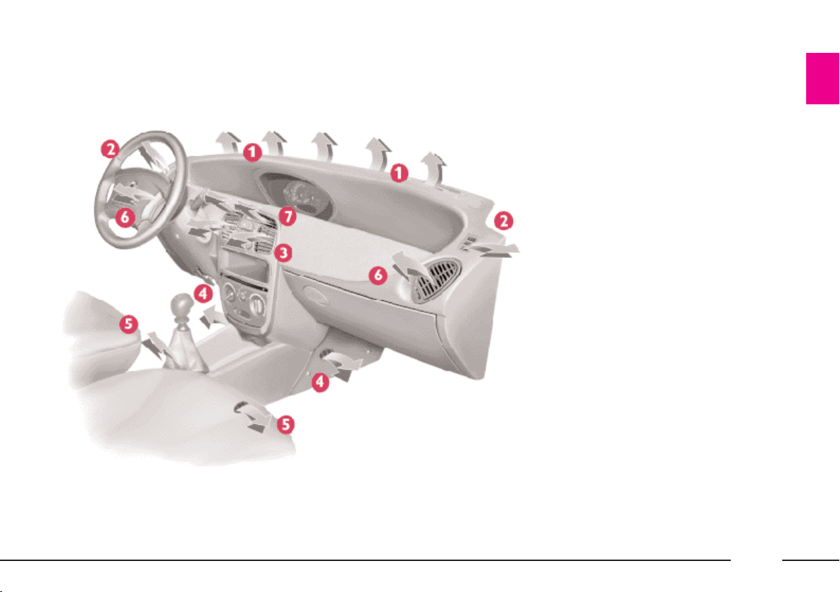
DASHBOARD
The presence and position of instruments and warning lights may vary according to the version of the car.
P4C00364
1. Fixed air vents for side windows - 2. Left-hand stalk (direction indicators/headlamps) - 3. Airbag - 4. Right-hand stalk (windscreen wiper/rear window wiper) - 5. Instrument panel - 6. Button panel with climate control button - 7. Radio-navigator or
sound system - 8. Front window demisting - 9. Passenger side airbag - 10. Speaker housing (tweeter) - 11. Side air vent - 12. Glove
compartment - 13. Air distribution knob - 14. Air recirculation slider - 15. Fan knob - 16. Air temperature adjustment knob -
17. Ignition switch - 18. Steering wheel adjustment lever - 19. Bonnet release lever - 20. Horn - 21. Object tray/Fusebox.
11
Page 15

The presence and position of instruments and warning lights may vary according to the version of the car.
P4C00365
1. Fixed air vents for side windows - 2. Left-hand stalk (direction indicators/headlamps) - 3. Airbag - 4. Right-hand stalk
(windscreen wiper/rear window wiper) - 5. Instrument panel - 6. Button panel - 7. Sound system housing - 8. Front window
demisting - 9. Speaker housing (tweeter) - 10. Side air vent - 11. Glove compartment - 12. Air distribution knob - 13. Air
recirculation slider - 14. Fan knob - 15. Air temperature adjustment knob - 16. Ignition switch - 17. Steering wheel adjustment lever - 18. Bonnet release lever - 19. Horn - 20. Object tray/Fusebox.
12
Page 16

THE LANCIA
CODE SYSTEM
To further protect your car from attempted theft, it has been fitted with
an electronic engine immobiliser system called “Lancia CODE”, which is
currently considered the most effective way of protecting your car against
theft. This system is automatically
activated each time the engine is
switched off. Each ignition key, in
fact, contains an electronic device
which modulates a radio-frequency
signal emitted by a special aerial during ignition. The modulated signal is
a “password” with which the control
unit recognises the key. Engine ignition is enabled only if the key is recognised by the system.
THE KEYS
Three types of key (fig. 1) are sup-
plied with the car.
The car is always supplied with a
single A key and B or C keys depending on the version:
– version without remote control,
two B keys;
– versions with door lock/unlock remote control, one B key and one C key;
Key A, with a burgundy grip, is the
“master” key. Only one of these keys
is provided, and it is used to store the
codes of new keys replacing ones that
have been lost or damaged, or when
storing duplicate key codes. Given its
importance, it should be kept in a safe
place (not in the car) and only be
used when absolutely necessary.
No repairs can be carried out on
the Lancia CODE system or the en-
P4C00056
gine control unit if this key is lost.
Key B, with a black grip, is the key
that is to be used normally. It will:
– start the engine
– unlock/lock the doors
– unlock/lock the boot
– unlock/lock the fuel tank cap.
– deactivate the passenger airbag.
Key C, (which may be supplied as
an alternative to the B key), has the
same functions as key B, plus the remote control function for the door
lock/unlock system.
The key is supplied together with the
CODE card (fig. 2) which bears:
D - the electronic code to be used for
emergency starting (see “In an emergency”);
P4C00057
fig. 1
fig. 2
13
Page 17

E - the mechanical key code to be
given to the LANCIA Dealership
when ordering duplicate keys;
F - the spaces for stickers bearing
the code of any remote controls provided.
The code numbers on the CODE
card and the key with the burgundy
grip must be kept in a safe place.
You should keep the electronic code
written on the CODE card with you
at all times in case it is necessary to
start the car using the emergency procedure.
OPERATION
Each time the ignition key is turned
to STOP or PARK, the protection
system will immobilise the engine.
When the key is turned to MAR at
engine startup:
1) If the code is recognised, the
warning lamp ¢ on the instrument
panel will flash briefly; this means
that the protection system has recognised the key code and disabled the
engine immobiliser; turn the key to
AVV to start.
2) If the code is not recognised, the
warning lamp ¢ and the warning
lamp will remain lit. Should this
happen, turn the key back
to STOP and then to MAR; if the engine remains immobilised, try using
the other keys supplied with the car.
If you are still unable to start the engine, use the emergency starting procedure (see “In an emergency”), and
take your car immediately to the
nearest LANCIA Dealership.
When travelling with the ignition
key on MAR:
1) If the warning lamp ¢ lights up
while the car is moving, it means that
the system is running a self-diagnosis
(e.g. due to a voltage drop).
The first time you stop you can test
the system: turn the ignition key to
STOP to switch off the engine then to
MAR again. Warning lamp ¢ will
switch on and should switch off again
after about 1 second.
If the warning light remains on, repeat the previous operations again
leaving the key at STOP for more
than 30 seconds. If the fault persists,
contact a LANCIA Dealership.
2) If the warning lamp ¢ flashes it
means that the car is not protected by
the immobiliser. Contact your LAN-
CIA Dealership immediately and get
them to store the codes of all the keys
in the memory.
IMPORTANT The electronic components inside the key may be damaged if the key is subjected to sharp
knocks.
IMPORTANT Each key given with
the car has its own code, different
from all the others, which must be
stored in the memory of the system’s
control unit.
14
Page 18

DUPLICATE KEYS
If you ask for extra keys, remember
that all the keys, both the new ones
and those you already possess, must
be stored in the memory (up to a
maximum of 7). Go directly to your
nearest LANCIA Dealership, taking
with you the burgundy “master” key,
all the keys in your possession and the
CODE card. The LANCIA Dealer-
ship may ask you to demonstrate that
you own the car.
The codes of any keys that are not
available when the new storage procedure is carried out will be deleted
from the memory to prevent any lost
keys being used to start the car.
The burgundy key, plus
all the other keys, and the
CODE card must be
handed over to the new owner
when selling the car.
DOOR LOCK/UNLOCK
REMOTE CONTROL (fig. 3)
The remote control is built into the
ignition key. It consists of a button C
and a LED D. The button operates
the control and the LED flashes while
the transmitter is sending the code to
the receiver.
This a radio-frequency remote control and must be used close to the car.
Ministerial homologation
With respect to the legislation in
force in each country on the use of radio frequencies:
– the market specific homologation
codes are given in the chapter “Accessory installation”;
– the homologation code is printed
on the ignition key-remote control for
the markets which require it.
P4C00058
fig. 3
15
Page 19

CHANGING THE BATTERIES
(fig. 4)
Change the remote control batteries
when the LED on the remote control
flashes once only when pressed.
Change the batterie with a similar
type as follows: open the plastic covers; insert the new batterie respecting
the polarity shown; close the plastic
covers.
Used batteries are an environmental hazard. Dispose of them in appropri-
ate containers as prescribed by the
law. Alternatively, take the batteries to a LANCIA Dealership who
will dispose of them correctly.
IGNITION SWITCH
The key can turn through four posi-
tions (fig. 5):
– STOP: engine off, key can be re-
moved and the steering column is
locked. Some electrical devices can be
used (e.g. sound system, central door
lock, etc.).
– MAR: drive position. All electrical
devices can be used.
– AVV: to start the engine.
P4C20003
– PARK: engine off, parking lights
lit, key can be removed, steering column locked. Press button A to turn
the key to PARK.
If the ignition switch has
been tampered with (e.g.
someone has tried to steal
your car), get a LANCIA Dealership to make sure it is still functioning properly before you start
driving again.
Always remove the key
when leaving the car so
that the controls cannot be
accidentally activated. Engage the
handbrake, and if the car is facing
uphill engage the first gear too.
With the car facing downhill en-
P4C00324
gage the reverse gear. Never leave
children alone in the car.
fig. 4
16
fig. 5
Page 20

STEERING COLUMN LOCK
To set: remove the ignition key from
the STOP or PARK position, and
turn the steering wheel until it locks.
To release: move the steering wheel
slightly as you turn the ignition key to
MAR.
Never remove the ignition
key while the car is moving. The steering wheel
would automatically lock as soon
as you tried to turn it. This also
applies when the car is being
towed.
INDIVIDUAL
SETTINGS
Adjustments must be
made only when the car is
stationary.
FRONT SEATS
Moving the seat backwards
or forwards
Lift the lever A (fig. 6) and push the
seat forwards or backwards. You are
in the correct position for driving
when your hands are resting on the
steering wheel rim and your arms are
slightly bent.
Once you have released
the lever, check that the
seat is firmly locked in the
runners by trying to move it back
and forth. Failure to lock the seat
in place could result in the seat
moving suddenly and dangerously.
Height adjustment
Pull out telescopic lever B (fig. 6);
raise or lower it as required.
IMPORTANT The adjustment must
only be made with someone sitting in
the seat.
Adjusting the reclining seat back
Turn knob C (fig. 6).
P4C00017
fig. 6
17
Page 21

Lumbar support adjustment
This adjustment gives better back
support.
To adjust, turn knob D (fig. 7).
HEAD RESTRAINTS (fig. 8) The rear head restraints (fig. 9) can
be removed to fold the seat back:
Remember: head restraints should be adjusted
to support the back of your
head and not your neck. Only if
they are in this position will they
– press tabs A and remove the head
restraint.
To refit, fit it in the holes until you
hear a click.
be able to provide effective protection in the event of a rear-end
shunt.
The height of the front head restraints can be adjusted to ensure that
the person’s head rests on it correctly.
fig. 7
18
P4C00159
fig. 8
P4C00390
P4C00391
fig. 9
Page 22

ACCESS TO THE BACK SEATS
(fig. 10)
You can easily get into the back
seats from either side.
Pull handle A up to fold the seat
back down and slide the seat forwards
(only for the passenger seat).
A recovery device with memory
makes it possible to automatically return the passenger seat to the position
it was in previously. Always ensure
the seat is locked properly in its runners by trying to move it back and
forth.
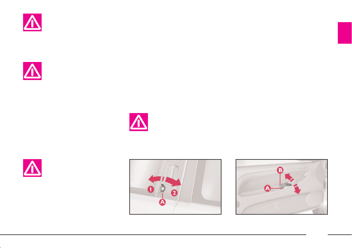
STEERING WHEEL (fig. 11)
The wheel must only be
adjusted while the car is
stationary.
To adjust the height of the steering
wheel:
1) Move lever A to position 1.
2) Adjust the steering wheel.
3) Return the lever to position 2 to
lock the wheel in place again.
Do not push on the power
steering limit switch for
more than 15 seconds with
the engine running. This causes
noise and could damage the system.
DRIVING MIRROR (fig. 12)
This mirror is adjustable. Move lever
A to shift the mirror to the following
positions:
1) normal position;
2) anti-dazzle position.
The mirror is also fitted with a safety
device that releases the mirror in the
event of impact.
fig. 10
P4C00396
fig. 11
P4C00392
P4C00062
fig. 12
19
Page 23

DOOR MIRRORS
Hand-adjustable (fig. 13)
Turn knob A inside the car.
Electrically-adjustable (fig. 14)
The mirrors can only be adjusted
electrically when the ignition key is at
MAR.
All you need to do is press any of the
four directions on switch A to perform
this operation.
Use switch B to select the mirror
(right or left) you want to adjust.
Electrically folding mirrors have an
electrical device for demisting the
mirrors that comes on automatically
when you turn on the rear window
heater.
If the mirror makes it difficult to get through narrow gaps, fold it from po-
sition 1 to position 2 (fig. 15).
When driving the mirrors
should always be in extended position 1.
The external curved rear
view mirrors slightly alter
the perception of distance.
fig. 13
20
P4C00063
fig. 14
P4C00023
P4C00317
fig. 15
Page 24

SEAT BELTS
HOW TO USE THE SEAT BELTS
(for the front and back side seats)
(fig. 16)
Pull the seat belt out gently; if the
belt jams, let it rewind for a short
stretch, then pull it out again without
jerking.
To fasten the seat belts, take the
tongue of fastener A and push it into
buckle B until you hear it click.
The lower part of the front seat belts
slides on a bar to make it easier for
you to get hold of the belt when
putting it on.
Press button C to unfasten the belts.
Guide the belt with your hand as it
rewinds to prevent it twisting.
The belt unwinds from the reel and
automatically adjusts to fit the passenger’s body, allowing him or her to
move in complete freedom. When the
car is parked on a slope the reel may
lock. This is quite normal.
The reel mechanism also prevents
the webbing coming out when it is
jerked or if the car brakes sharply, is
in a collision or when taking bends at
high speed.
For maximum safety,
P4C00397
and make sure the seat belt fits
closely across your chest and hips.
keep the back of your seat
upright, lean back into it
ADJUSTING THE FRONT SEAT
BELT HEIGHT (fig. 17)
Make the height adjustment when the car is stationary.
Always adjust the height of the seat
belt to fit the person wearing it. This
could greatly reduce the risk of injury
in the case of collision.
P4C00050
fig. 16
fig. 17
21
Page 25

The belt is adjusted properly when
the webbing passes approximately
halfway between the edge of the
shoulder and the neck.
The seat belt can be adjusted to one
of four different heights.
To lift the belt
Lift loop B (fig. 17) to the required
position.
To lower the belt
Press knob A (fig. 17) and move
loop B down to the position required.
After you have made the
adjustment, always make
sure the slider the loop is
attached to catches firmly in one of
the fixed positions and cannot
move. To check this, release the
knob and push again so that it can
catch into place if it is not properly
latched in position.
PRETENSIONERS
The Lancia Y is fitted with pretensioners to enable the seat belts to offer even more effective protection.
These devices “feel” that a violent collision is in progress, via a sensor, and
call in a few inches of webbing. The
pretensioner, therefore, ensures the
belt is adhering perfectly to the body
before it begins to stop the wearer
moving forward.
When the seat belt locks, it indicates
the pretensioner has been activated.
The belt will not wind back even if
accompanied manually.
A small amount of smoke may be
noticed: this is not harmful and does
not indicate the beginning of a fire.
The pretensioner needs no maintenance or lubrication. Any modification to its original features will nullify
the pretensioner’s effectiveness. If water or mud accidentally get into the
pretensioner as a result of floods or
storms, the device must be replaced.
For maximum pretensioner protection, make sure your seat belt fits
snugly to your chest and hips.
Never dismantle or tamper with pretensioner
components. Any interven-
tion must be performed by skilled
and qualified personnel. Always
have interventions performed at a
LANCIA Dealership.
22
Page 26

The pretensioners can
only be used once. After
they have been activated,
have them replaced at a LANCIA
Dealership.
The device was made to last 10
years from the manufacturing date
shown in the specific adhesive label. The pretensioners must be
changed before expiry.
Work involving knocks,
vibrations or localised
heating (maximum 6 hours
at over 100° C) near the pretensioner unit can cause damage or
even trigger the device. Vibrations
caused by uneven roads or accidentally driving over small bumps
(e.g. curbs), etc., do not fall into
this category. See a LANCIA Dealership if work is required on the
device.
USE OF THE REAR SEAT BELTS
(fig. 18)
The belts for the back seats must be
worn as shown.
To ensure the correct buckle is used,
the tongues of the side seat belts will
not fit into the buckle of the middle
seat belt.
You should put the belt on when you
are sitting upright and leaning back
in your seat.
IMPORTANT The seat belt has
been adjusted correctly when it fits
snugly across the wearer’s hips.
Remember, in the case of
a violent collision, back
seat passengers not wear-
ing seat belts also represent a serious danger to the passengers in
the front.
P4C00066
fig. 18
23
Page 27

USING THE REAR CENTRAL
SEAT BELT (fig. 19)
To fasten the seat belt: push the
tongue of fastener A into slot B of the
buckle until you hear it click.
To unfasten the seat belt: press
button C.
To adjust the seat belt: slide the
webbing through adjuster D, pulling
end E to shorten it and length F to
lengthen it.
IMPORTANT The belt is adjusted
properly when it fits closely across the
hips.
GENERAL INSTRUCTIONS
FOR THE USE OF THE SEAT
BELTS
The driver is responsible for respecting and making sure the passengers respect the local rules on the use
of seat belts.
Make sure all seat belts
(both front and back) are
fastened at all times! You
increase the risk of serious injury
or death in a collision if you travel
with the belts unfastened even if
your car is fitted with the airbag
system.
The webbing must not be
twisted. The upper section
must pass across the
shoulder and chest diagonally. The
lower part must fit closely across
the passengers’ hips and not the
abdomen, to prevent them sliding
forward (fig. 20). Do not use clips,
fasteners, etc. to prevent the belt
adhering to the passenger’s body.
fig. 19
24
P4C00067
P4C00068
fig. 20
Page 28

Never travel with a child
sitting on a passenger’s lap
with a single seat belt to
protect them both (fig. 21).
If the belt has undergone
serious strain, for example
following an accident, re-
place the belt with its anchorages,
the anchorage screws and the pretensioner. Even if there is no visible damage, the resistance properties may have deteriorated.
SEVERE DANGER:
if the car has a pas-
senger airbag, do
not place the child seat on the
front seat.
Seat belts must also be worn by expectant mothers: the risk of injury in
the case of accident is much greater
for them, too, if they do not have a
seat belt on.
Of course, expectant mothers must
position the lower part of the belt very
low down so that it passes under the
stomach, (fig. 22).
HOW TO MAINTAIN
THE SEAT BELTS
IN GOOD WORKING ORDER
1) When wearing the seat belts, al-
ways ensure they are not twisted but
lie flat across the chest and hips and
ensure that they run easily and freely.
2) Following a serious accident, replace the belt being worn at the time,
even if it does not seem damaged.
3) When cleaning the belts, wash
them by hand with water and neutral
soap, rinse them and let them dry in
the shade. Do not use strong detergents, bleach, colouring or any other
chemical substance that could weaken
the fibres.
4) Do not allow the reels to get wet:
they are only guaranteed to work
properly if they remain dry.
fig. 21
P4C00173
P4C00069
fig. 22
25
Page 29

TRANSPORTING
CHILDREN SAFELY
For the best protection in the event
of a crash, all passengers must be
seated and wearing adequate restraint
systems.
This is especially relevant for children.
A child’s head, in respect to that of
an adult, is larger and heavier in relation to the body. Moreover the muscular and bone structure is not fully
developed. For these reasons, children
require specific restraint systems, different to those required by adult passengers.
The results of research on the best
child restraint systems are contained
in the European Standard ECE-R44.
This Standard enforces the use of restraint systems classified in four
groups, (fig. 23):
Group 0 weight 0 - 10 kg
Group 1 weight 9 - 18 kg
Group 2 weight 15 - 25 kg
Group 3 weight 22 - 36 kg.
The groups partially overlap. This is
because there are systems which cover
more than one weight group.
All restraint systems must show homologation data and control marks on
a tag securely fastened to the system
and that cannot be removed.
Children weighing more than 36 kg
and taller than 1.5 m are, with reference to restraint systems, considered
adults and can wear normal seat belts.
We recommend using Lineaccessori
LANCIA child restraint systems for
each weight group as they have been
specifically designed for LANCIA vehicles.
P4C00312
fig. 23
26
Page 30

We recommend sitting
children on the rear seat.
This is the most protected
position in the event of a crash.
Never fit child restraint systems in
the front passenger seat in vehicles
with a passenger airbag. The inflated airbag could cause even fatal injury, regardless of the severity of the crash which triggered it
off.
Children can sit in the front passenger seat in cars with passenger
side airbag only if the system has
been deactivated. In this case, always make sure that the amber instrument panel warning light is on
to confirm that the airbag has been
deactivated.
fig. 24
GROUP 0
Babies up to 10 kg are to be seated
in a cot type seat facing backwards
and supporting the child’s head. This
ensures there is no stress on the child’s
neck in sudden deceleration
The cot is secured with the seat belts
as shown in (fig. 24). The child must
be strapped to the carrier.
The figure is only an example for the installation.
Follow the instructions
provided with the restraint system
you are using.
P4C00310
fig. 25
GROUP 1
Children from 9 kg are to be seated
facing forward in child seats with
front cushions, (fig. 25). The vehicle
seat belt secures both seat and child.
The figure is only an example for the installation.
Follow the instructions
provided with the restraint system
you are using.
There are child restraints
for Groups 0 and 1 which
are fastened with the vehi-
cle seat belts by means of an attachment on the seat back. The
child is then secured to the seat
with specific straps. Due to their
P4C00311
weight, child seats can be dangerous if they are not fitted correctly
(e.g. by placing a cushion between
the seat and the belts). Always follow carefully the installation instructions provided with the child
restraint system you are using.
27
Page 31

GROUP 2
Children from 15 kg can be secured
directly with the vehicle seat belts.
The child seat has the purpose of positioning the child correctly with respect to the seat belt so that the diagonal section crosses the child’s chest
(never the child’s throat) and the horizontal section fits snugly on the
child’s hips (and not on the child’s
abdomen) (fig. 26).
The figure is only an example for the installation.
Follow the instructions
provided with the restraint system
you are using.
GROUP 3
Children from 22 kg up only require
a cushion to lift them (fig. 27). The
size of the child’s chest no longer requires a support to space the child’s
back from the seat back.
Children taller than 1.5 m can wear
seat belts like adults.
To sum up the safety precautions
to follow when transporting children:
1) Child restraint systems should be
installed on the rear seat as this is the
most protected area in the car in the
event of a crash.
2) Children must never be seated in
the front passenger seat in cars with
passenger seat airbag.
P4C00313
3) Always check that the amber instrument panel warning light comes
on after deactivating the passenger
front airbag (in model/versions where
fitted).
4) Follow the instructions for fastening the specific child restraint system you are using. These must be
provided by the manufacturer. Keep
the child restraint system installation
instructions with the vehicle documents and this handbook. Never use
a second-hand child restraint system
without installation instructions.
5) Always check the seat belt is well
fastened by pulling the webbing.
6) The child restraint system is designed for one child only. Never carry
two children in one restraint system.
7) Always check the seat belts do not
fit around the child’s neck.
8) While travelling do not let the
child sit incorrectly or release the belts.
P4C00314
9) Passengers should never carry
children on their laps. No-one, however strong they may be, can hold a
child in the event of a crash.
10) Replace the child restraint system after an accident.
fig. 26
28
fig. 27
Page 32
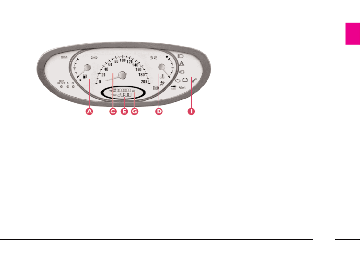
INSTRUMENT PANEL
fig. 28
P4C00366
1.2 16V MN blue VERSION
A - Fuel gauge with reserve warning
light.
C - Speedometer.
D - Engine coolant temperature
gauge with high temperature warning
light.
E - Clock.
G - Odometer and trip meter.
I - Indicators and warning lights.
29
Page 33
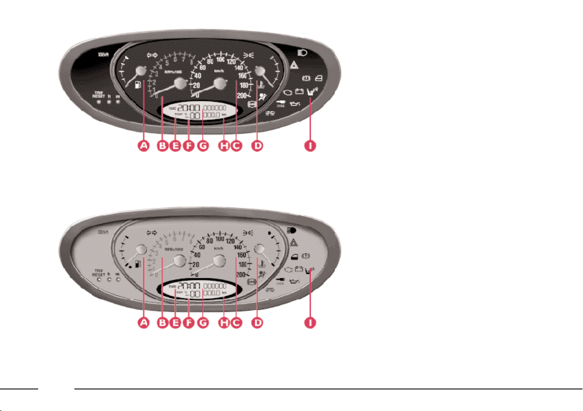
fig. 29
fig. 30
P4C00367
P4C00368
LS-LX VERSIONS
A - Fuel gauge with reserve warning
light.
B - Rev counter.
C - Speedometer.
D - Engine coolant temperature gauge
with high temperature warning light.
E - Clock.
F - Outside temperature gauge.
G - Odometer.
H - Trip meter.
I - Indicators and warning lights.
1.2 16V MN red VERSION
A - Fuel gauge with reserve warning
light.
B - Rev counter.
C - Speedometer.
D - Engine coolant temperature gauge
with high temperature warning light.
E - Clock.
F - Outside temperature gauge.
G - Odometer.
H - Trip meter.
I - Indicators and warning lights.
30
Page 34
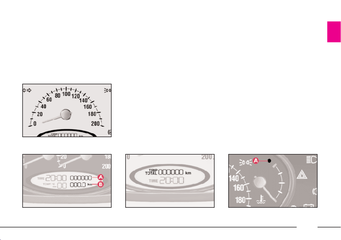
INSTRUMENTS
SPEEDOMETER (fig. 31)
fig. 31
ODOMETER AND TRIP
METER
For LS-LX - 1.2 16V MMN red ver-
sions (fig. 32)
A - Odometer.
B - Trip meter.
Press “Reset” button C (fig. 36) to
reset.
For the 1.2
16V MN blue version (fig.
33), only the odometer is displayed;
P4C00369
to display the trip meter, press button
C (fig. 36) slightly and release.
Press button C (fig. 36) for more
than 3 seconds to reset the trip
odometer.
Press button C (fig. 36) again to return to the odometer display.
COOLANT TEMPERATURE
GAUGE (fig. 34)
If warning lamp A lights up, it
means that the engine coolant is too
hot.
Under normal conditions, the needle
of the temperature gauge should between 1/4 and 3/4 of the scale. If it
approaches the red section it means
the engine is being overtaxed and you
should reduce your demands on it.
IMPORTANT The gauge will point
to low temperature and the excessive
temperature warning light A will
come on to indicate a fault in the system. Contact a LANCIA Dealership
to have the system checked.
fig. 32
P4C00370
fig. 33
P4C00371
P4C00372
fig. 34
31
Page 35
Even travelling too slowly when the
outside temperature is very hot can
cause the needle to approach the red
sector. In this case it is better to stop
and turn off the engine. After a few
moments you can start the engine
again and accelerate slightly.
If the situation persists
even after the measures
you have taken, turn off
the engine and have the car seen to
at a LANCIA Dealership.
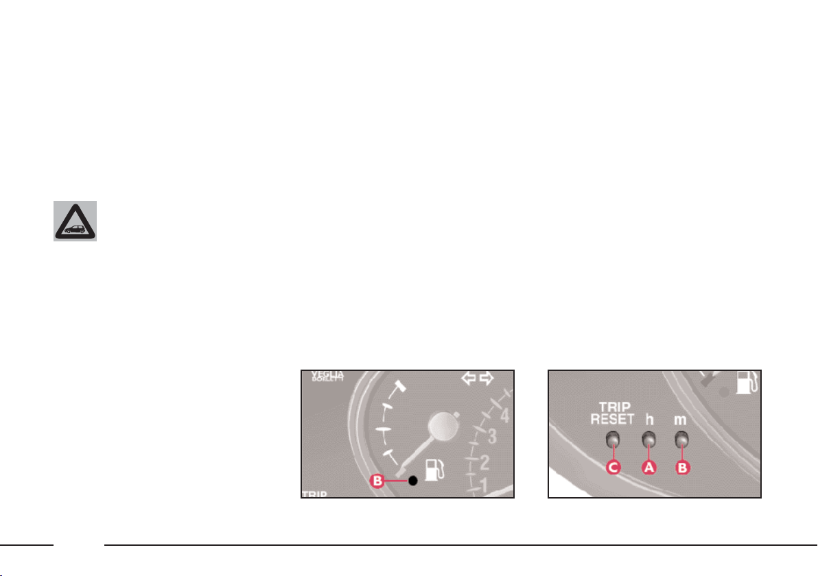
FUEL GAUGE (fig. 35)
If reserve warning light B comes on
it means there are between 5 and 8
litres of fuel left in the tank.
Do not drive when the tank is nearly
empty: possible changes in fuel delivery could damage the catalyser.
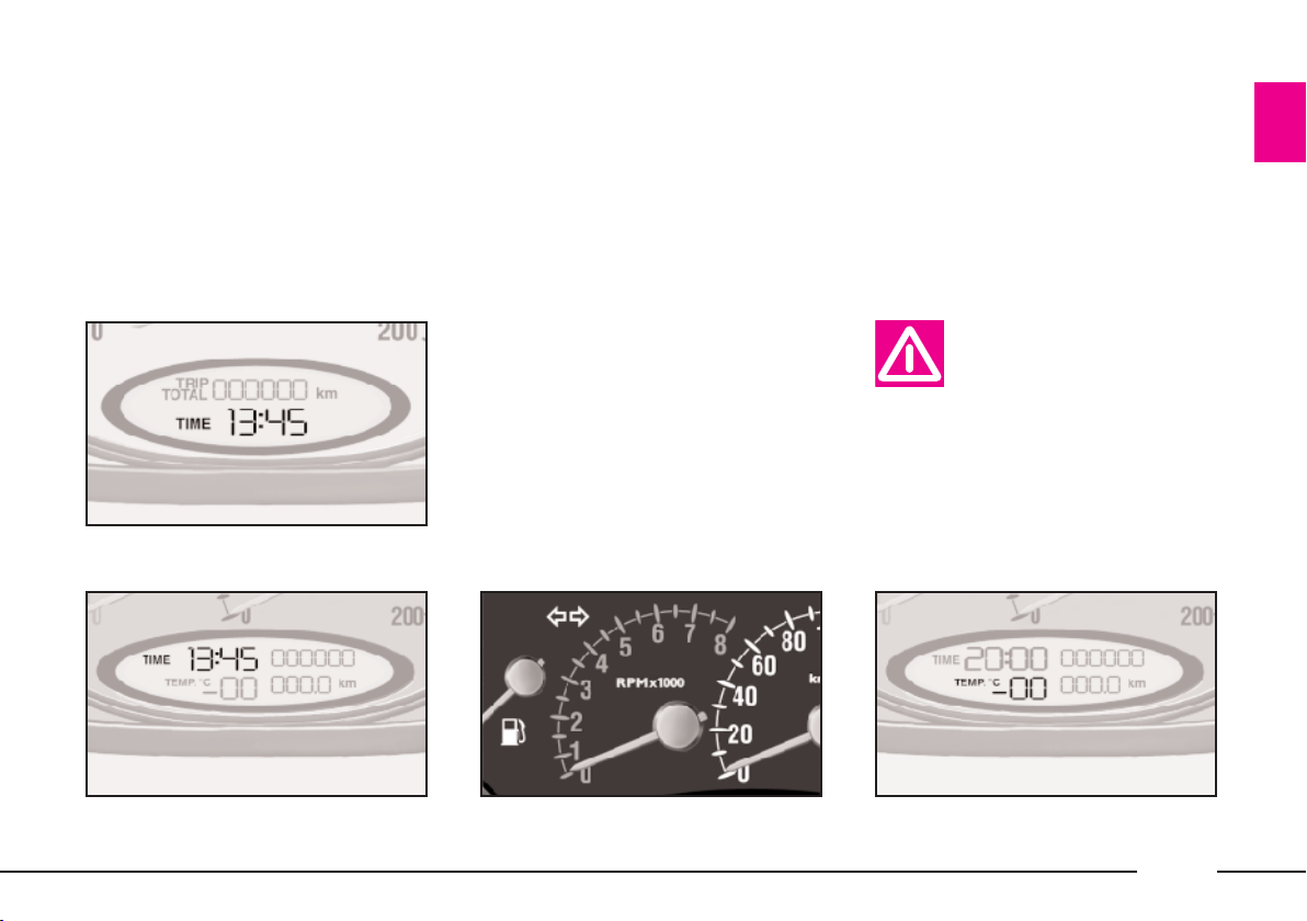
CLOCK
Press control A (fig. 36) to adjust the
hour.
Press control B to adjust the minutes.
Each time one of the control buttons
is pressed, the hours (A) or the minutes (B) will move forwards one unit.
32
fig. 35
P4C00373
P4C00374
fig. 36
Page 36
– (fig. 37) - 1.2 16V MMN blue version.
– (fig. 38) - LS - LX - 1.2 16V MMN
red
versions.
fig. 37
REV COUNTER (fig. 39)
If the needle is in the red zone it
shows your car’s engine is overrevving. This is only acceptable for a
few moments.
IMPORTANT The electronic injection control system progressively
blocks the flow of fuel when the
pointer goes into the red zone leading
to a progressive loss of engine power.
P4C00375
OUTSIDE TEMPERATURE
GAUGE (fig. 40)
The correct temperature reading is
given when the car is travelling.
When the temperature
displayed is near zero,
take great care as there is
the risk of ice on the road.
fig. 38
P4C00376
fig. 39
P4C00377
P4C00378
fig. 40
33
Page 37

WARNING LIGHTS
The warning lights will come on in
the following cases:
LOW ENGINE
v
engine oil falls below the normal level.
When the key is turned to MAR, the
light comes on but should go out the
moment the engine is started.
A delay in the light going out is only
acceptable if the engine is idling.
If the engine has been taxed heavily,
the light might flash when idling but
should go out on accelerating slightly.
off and get in touch with a LANCIA
Dealership.
OIL PRESSURE (red)
When the pressure of the
If the warning lamp v
lights up while the car is
moving, switch the engine
BATTERY NOT
w
When there is a fault in the current
generating system.
Contact a LANCIA Dealership as
soon as possible to prevent draining
the battery.
The warning lamp will light up when
the ignition key is turned to MAR, but
should go out as soon as the engine
has started.
x
In three cases:
1. When the handbrake is engaged.
2. When the brake fluid level falls be-
low the minimum.
3. With the > warning light to indicate an EBD electronic brake force
corrector failure.
RECHARGED
PROPERLY (red)
HANDBRAKE ON/
LOW BRAKE FLUID
LEVEL (red)
If the x warning light
comes on when travelling,
check whether the hand-
brake is engaged. If the warning
light stays on and the handbrake
is not engaged, stop immediately
and contact a LANCIA Dealership.
AIRBAG MALFUNCTION
û
cient.
turned to MAR and go out after approximately four seconds. Immediately contact a LANCIA Dealership if the warning light either
does not come on or stays on when
travelling.
´
closed.
(red)
When the system is ineffi-
The instrument panel
warning light should come
on when the ignition key is
DOORS NOT CLOSED
PROPERLY (red)
When a door is not fully
34
Page 38
HAZARD LIGHTS
r
switched on.
¢
key at MAR):
1. A single flash - indicates that the
key code has been recognised. The engine can be started.
2. A constant light - indicates that the
key code has not been recognised. To
start the engine, follow the emergency
startup procedure described in the “In
an emergency” section.
3. A flashing light - indicates that the
car is not protected by the immobiliser system. The engine can be
started however.
(red) (flashing)
When the hazard lights are
LANCIA CODE
(amber)
In three ways (with ignition
ABS (ANTI-LOCKING
>
When the ABS system is inefficient.
The normal braking system continues
to work but you should have the car
seen to at a LANCIA Dealership as
soon as you can.
The warning lamp will light up when
you turn the key to MAR, but it
should go out as soon as the engine
starts.
> and x light up simultaneously
when the engine is running, this
indicates an EBD fault. This
means that violent braking could
cause early locking of the rear
wheels causing the car to skid.
Drive very carefully to the nearest
LANCIA Dealership to have the
system checked.
SYSTEM) FAILURE
(amber)
The car is fitted with an
electronic brake distributor (EBD). If warning lights
If only warning light >
switches on when the en-
gine is running, this usually indicates an ABS fault. In such
cases the braking system is still efficient, although the anti-locking
device does not function. The EBD
system may also be less efficient.
Go to a LANCIA Dealership immediately, taking care not to brake
suddenly, and have the system
checked.
EOBD SELFDIAGNOSTIC SYSTEM
(amber)
In normal conditions, the warning
light will come on when the ignition
key is turned to MAR and should go
out as soon as the engine is started.
The initial lighting up shows that the
warning light is working properly.
If the warning light either stays on or
comes on while travelling:
1. Fixed light - warning of a fuel
feed/ignition system failure which
35
Page 39
may increase emissions in exhaust or
cause possible drops in performance,
poor handling and high consumption.
In such conditions, you can continue
driving but you should not tax the engine and you should moderate the
speed. Prolonged use with the warning light on can cause damage. Contact a LANCIA Dealership as soon
as possible.
The warning light will go out when
the failure disappears. In any case, the
system will store the error.
2. Flashing light - warning that the
catalyser can be damaged (see
“EOBD system” in this chapter).
If the warning light starts flashing, release the accelerator pedal and slow
the engine until the warning light
stops flashing. Continue driving at
moderate speed, preventing the warning light from coming on again. Contact a LANCIA Dealership as soon
as possible.
Contact a Lancia Dealership as soon as possible if
the warning light ei-
ther does not come on when the
key is turned to MAR or comes on,
with fixed or flashing light, when
travelling.
BRAKE LIGHTS
T
bulbs fails to work. A fault in the
third brake light is not indicated.
When the passenger airbag has been
deactivated by means of the specific
key switch.
FAULTY (amber)
When one of the brake light
PASSENGER AIRBAG
DEACTIVATED
(amber)
The warning light should
come on for approximately
four seconds and flash for
other four seconds only when the
key is turned to MAR and the passenger’s front airbag switch is
turned to ON. If the warning light
either does not come on or comes
on when travelling, stop immediately and contact a LANCIA Dealership.
DIRECTION
y
When the direction indicator control
stalk is pushed up or down.
3
turned on.
1
lights are lit.
INDICATORS
(green) (flashing)
EXTERIOR
LIGHTING (green)
When the side-/taillights are
MAIN-BEAM
HEADLIGHTS (blue)
When the main-beam head-
36
Page 40
HEATING AND VENTILATION
Key to (fig. 41)
1 - Windscreen defrosting/demist-
ing vent.
2 - Front side windows defrost-
ing/demisting vent.
3 - Central adjustable vents for
sending air to front-seat passengers.
4 - Side vents for sending air to feet
of front-seat passengers.
5 - Side vents for sending air to feet
of back-seat passengers.
6 - Side adjustable vent for sending
air to front-seat passengers.
7 - Vent for sending air above the
heads of those in the front seats.
fig. 41
P4C00398
37
Page 41
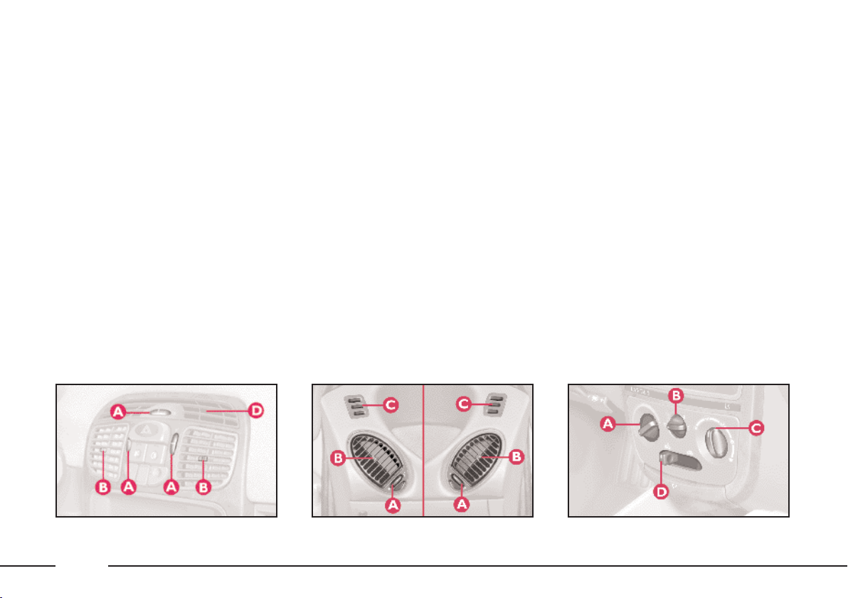
AIR VENTS (fig. 42 and 43)
The vents can be rotated upwards or
downwards.
A - Control for directing the air flow:
rotated towards ¥orà= vent open;
rotated towards ç= vent closed.
B - Control for regulating air flow.
C - Fixed vent for side windows
(fig. 43).
D - Fixed vent for front-seat pas-
senger (fig. 42).
CONTROLS (fig. 44)
A - Air temperature knob (mixture
of hot/cold air).
B - Fan knob, which may have 3 or
4 speeds according to the version.
C - Air distribution knob.
D - Air recirculation slider. This pre-
vents air from being taken in from
outside.
HEATING
1) Air temperature knob: pointer in
the red sector.
2) Fan knob: pointer set at the speed
required.
3) Air distribution knob: pointer set
at:
to warm the feet and demist the
≤
windscreen at the same time;
to generally warm the passenger
≥
compartment;
to warm the feet and direct cooler
μ
our towards the face (“bi-level” function).
4) Recirculation slider: to speed up
heating, move the air recirculation
slider to position T, which means
only inside air is recirculated.
fig. 42
38
P4C00325
fig. 43
P4C00081
P4C00212
fig. 44
Page 42

DEMISTING AND/OR
DEFROSTING OF
THE WINDSCREEN
AND FRONT SIDE WINDOWS
1) Air temperature knob: pointer in
the red sector -.
2) Fan knob: pointer at the maxi-
mum speed -.
3) Air distribution knob: pointer at
-.
4) Air recirculation slider at H,
means that air is taken in from the
outside.
When the windscreen and windows
have been demisted, adjust the controls to keep the windows as clear as
possible.
IMPORTANT If fitted, the climate
control is very useful for speeding up
demisting because it dries the air.
Simply adjust the controls for the
demisting function and turn on the
climate control by pressing button √.
DEMISTING AND/OR
DEFROSTING OF THE REAR
WINDOW
Press button (. The electric mirror
demisting device also comes on.
As soon as the rear window is clear,
you should release the button.
VENTILATION
1) Centre and side vents: fully open.
2) Air temperature knob: pointer in
the blue zone.
3) Air recirculation slider: pointer at
, which means that air is taken in
H
from outside.
4) Fan knob: pointer at the speed re-
quired.
5) Air distribution knob: pointer
at ¥.
AIR RECIRCULATION
When the slider is in position T
only the inside air is circulated.
IMPORTANT This function is particularly useful when the outside air
is heavily polluted (in a traffic jam,
tunnel, etc.). You are advised against
using this function for long periods,
however, especially if there are a lot
of people in the car or on cold and
raining days, since this considerably
increases the possibility of the windows misting up and will reduce visibility effecting driving conditions.
39
Page 43

CLIMATE CONTROL
SYSTEM
The climate control system is ad-
justed manually.
CONTROLS (fig. 45)
A - Air temperature knob (mixture
of warm and cold air).
B - Fan knob.
C - Air distribution knob.
D - Air recirculation slider, to elim-
inate external air.
IMPORTANT The recirculation
function allows to cool the air faster.
It is particularly useful when the outside air is heavily polluted (in a traffic jam, tunnel, etc.). You are advised
against using this function for long
periods, however, especially if there
are a lot of people in the car or on
cold and raining days, since this considerably increases the possibility of
the windows misting up and will reduce visibility effecting driving conditions.
E - Climate control on/off switch.
When the climate control system is
on, the fan will automatically come on
at the first speed.
The system uses R134a
P4C00326
not damage the environment.
Never use R12 fluid as it is incompatible with the system’s components and also contains CFC.
refrigerating liquid. If it
accidentally leaks it will
COOLING
1) Air temperature knob: pointer in
the blue sector.
2) Climate control system: press
switch√and move the air recirculation slider to T.
3) Fan knob: pointer at required
speed.
4) Air distribution knob: pointer at
.
¥
To reduce the cooling effect: move
the air recirculation slider to H, increase the temperature and decrease
the fan speed.
fig. 45
40
Page 44

IMPORTANT The climate control
is very useful for speeding up demisting because it dries the air. Simply
adjust the controls for the demisting
function and turn on the climate control by pressing button √.
IMPORTANT The versions with climate control have a factory-fitted
pollen filter.
IMPORTANT The climate control
compressor will be temporarily excluded when accelerating sharply, and
reengaged after an established period
of time.
STEERING
COLUMN STALKS
LEFT-HAND STALK
This stalk controls the following out-
side lights:
– side/taillights;
– dipped beam headlights;
– main beam headlights;
– direction indicators.
The outside lights can only be lit up
with the control stalk when the ignition key is at MAR.
When the outside lights are turned
on, the instrument panel and the various controls located in the dashboard
light up.
Side and taillights (fig. 46)
These come on when you turn
knurled switch from å to 6. Instrument panel indicator light 3 comes
on.
Dipped beam headlights (fig. 47)
These come on when you turn the
knurled switch from 6 to2.
Main beam headlights (fig. 48)
Push the stalk forwards towards the
dashboard with the ring at 2to
switch the headlights on.
Instrument panel indicator light 1
comes on.
To return to dipped beams, pull the
stalk back towards the steering wheel.
fig. 46
P4C00085
P4C00086
fig. 47
41
Page 45

To flash the lights (fig. 49)
Pull the stalk towards the steering
wheel (temporary position).
fig. 48
Direction indicators (fig. 50)
Move the stalk as follows to turn on
the direction indicators:
up - for the right indicator;
down - for the left indicator.
Instrument panel indicator light y
flashes.
The direction indicators automatically return to the neutral position
when the car straightens up.
P4C00087
If you want the indicator to flash
briefly, move the stalk up or down
without it clicking into position. When
you let it go it will return to its original position.
RIGHT-HAND STALK
Windscreen wash/wipe (fig. 51)
This feature can only work when the
ignition key is at MAR.
Controls:
0 - windscreen wiper off;
1 - flick wipe;
2 - slow continuous wipe;
3 - fast continuous wipe;
4 - temporary function: when you
release the stalk it returns to position
0 and automatically turns off the
windscreen wiper.
fig. 49
42
P4C00088
fig. 50
P4C00089
P4C00090
fig. 51
Page 46

When you pull the lever towards the
steering wheel (fig. 52), a jet of liquid
shoots out from the windscreen
washer.
Rear window wash/wipe (fig. 53)
This function is only possible when
the ignition key is at MAR.
Controls:
1) turn the control from å to ' for
continous wiper operation;
2) when you push the control stalk
forward (temporary position), a jet of
liquid shoots out from the rear window washer and the rear window
wiper comes into operation. When you
let the lever go again the rear window
washer/ wiper ceases to function.
CONTROLS
HAZARD LIGHTS
These come on when switch A
(fig. 54) is pressed, regardless of the
position of the ignition key.
When these lights are on, the panel
warning light rflashes.
Press the switch again to turn the
lights off.
fig. 52
P4C00091
fig. 53
P4C00092
P4C00343
fig. 54
43
Page 47

The use of hazard lights
is subject to the highway
code. Keep to the prescrip-
tions in force in the country you
are driving in.
CONTROL BUTTONS (fig. 55)
These are situated between the cen-
tre air vents.
They only function when the igni-
tion key is at MAR.
All buttons light up when pressed in.
A - To switch the front foglights
on/off. These lights can only be
switched on if the outside lights are
already on.
B - To switch the rear foglights on/
off. These lights can only be switched
on if the dipped headlights and/or the
front foglights are already on.
The rear foglights will automatically
be turned off when the engine is
switched off or when switching from
dipped beam headlights and/or front
foglights to side lights.
When the engine is restarted or
the dipped headlights are switched
back on in the presence of fog, the
rear foglight button must be
pressed to switch the rear foglights
on again.
IMPORTANT The rear fog light
may annoy the drivers following you
when visibility is good. Consequently,
P4C00344
use the light only when required.
C - To switch the heated rear window on/off. It will switch on the door
mirrors demisting device at the same
time, if this feature is included.
D - To switch the climate control
system on and off.
FUEL CUT-OFF SWITCH
This is a safety cut-out which comes
into play in the case of an accident
and blocks the fuel supply, thereby
stopping the engine.
After an accident, turn the ignition key to STOP to prevent the
battery running down.
fig. 55
44
Page 48
If, after an accident, you
can smell petrol or see that
the fuel feed system is
leaking, do not reset the switch to
avoid the risk of fire.
If you cannot see any fuel leaks and
the car is in a fit state to continue its
journey, press A (fig. 56) to reactivate
the fuel supply system.
INTERIOR
EQUIPMENT
GLOVE COMPARTMENT/
ODDMENT TRAY
To open the compartment, pull han-
dle A as shown in (fig. 57).
On the flap there is a special indent
for inserting a pen or pencil.
Do not travel with the
glove compartment open
as this could cause injury
in the event of an accident.
CEILING LAMP (fig. 58)
The ceiling lamp will automatically
light up when one of the front doors
is opened.
If the doors are closed, the lamp can
be switched on by pressing the side of
the lens.
fig. 56
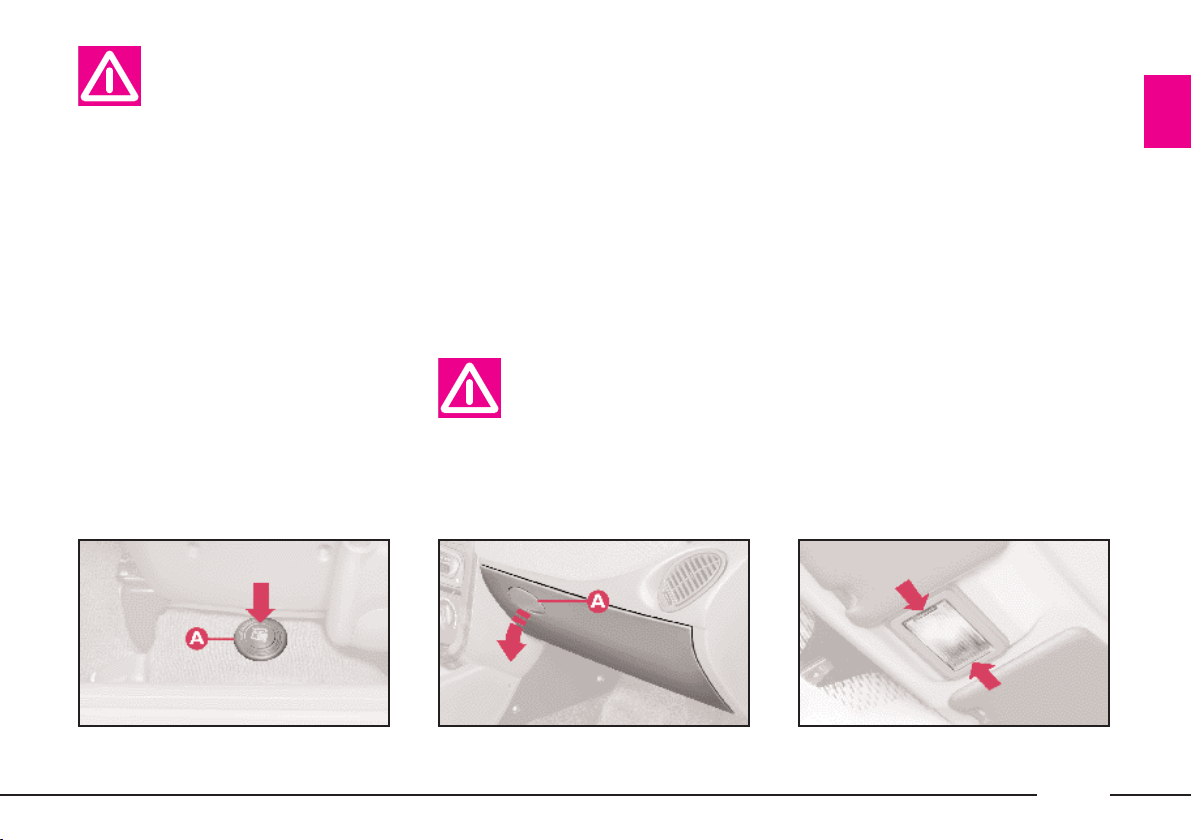
P4C00016
fig. 57
P4C00095
P4C00096
fig. 58
45
Page 49
CEILING LAMP (fig. 59)
Switches A and B switch the ceiling
lights on and off.
The following conditions are created
according to the position of these
switches:
– with switch A in the centre po-
sition, light C in the ceiling lamp will
come on when the doors are opened;
– with switch A moved to the left,
light C in the ceiling lamp is off and
will not light up if the doors are
opened;
– with switch A moved to the
right, light C in the ceiling lamp will
light up regardless of whether the
doors are open or not.
Switch B will switch the map-read-
ing light D on/off (spot light).
IMPORTANT Before getting out of
the car, make sure that switch A is in
the centre position; the ceiling light will
then go out when the doors are closed
and you will not drain the battery.
ASHTRAY AND CIGAR LIGHTER
How to use them:
1) Open flap A (fig. 60) in the di-
rection of the arrow to reach the cigar
lighter and the ashtray.
2) Press button B: after around fifteen seconds it returns to its initial po-
sition and the cigar lighter is ready to
use.
The ashtray can be removed.
IMPORTANT Make sure that the
cigar lighter does in fact pop out after it has been pushed in.
The rear seats have a concealed ashtray in the right side panel.
Follow the direction of the arrow to
use and extract the ashtray (fig. 61).
fig. 59
46
P4C00097
fig. 60
P4C00215
P4C00099
fig. 61
Page 50
Do not use the ashtray as
a waste-paper basket: the
paper could set fire if it
comes into contact with a smouldering cigarette stub.
The cigar lighter gets very
hot. Be careful how you
handle it and make sure it
is not used by children: danger of
fire and/or burns.
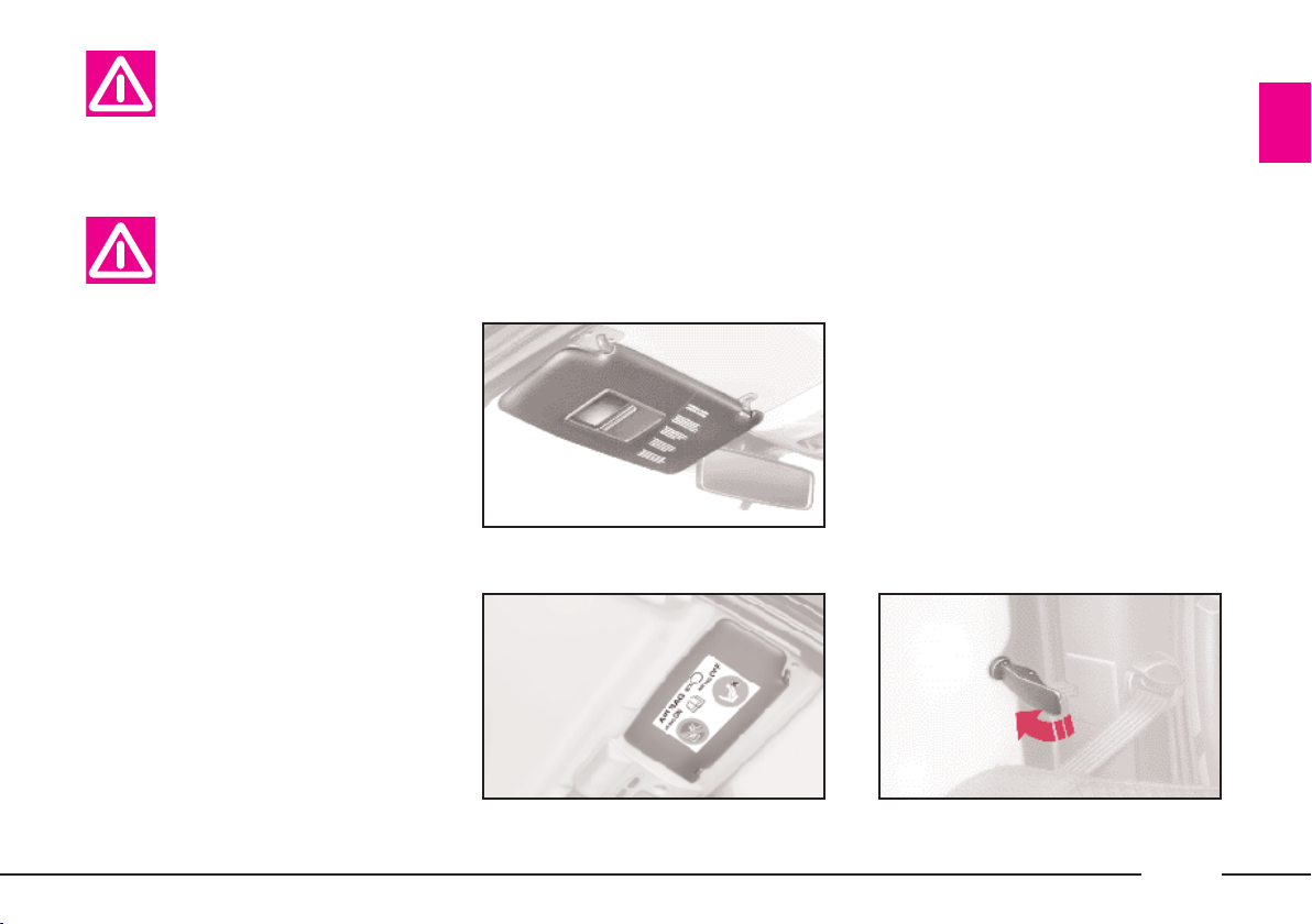
SUN VISORS (fig. 62)
These are positioned to the sides of
the driving mirror. They can swing up
or down or be pivoted sideways.
On the back of the driver’s sun visor, there is a document pocket with
a vanity mirror and protective flap.
The inside of the passenger’s sun visor is only fitted with a vanity mirror.
The symbol indicating the presence
of a front passenger airbag is printed
on the under-side of the sun visor
(visible when the visor is pushed up)
(fig. 63).
fig. 62
REAR SIDE WINDOWS
These windows are hinged:
1) Move the lever as shown in
(fig. 64).
2) Push the lever outwards until the
window opens completely.
3) Push the lever back until you hear
it lock into place.
To close these windows, reverse the
above procedure until you hear the
lever click back into position.
P4C00100
P4C00424
P4C00024
fig. 63
fig. 64
47
Page 51
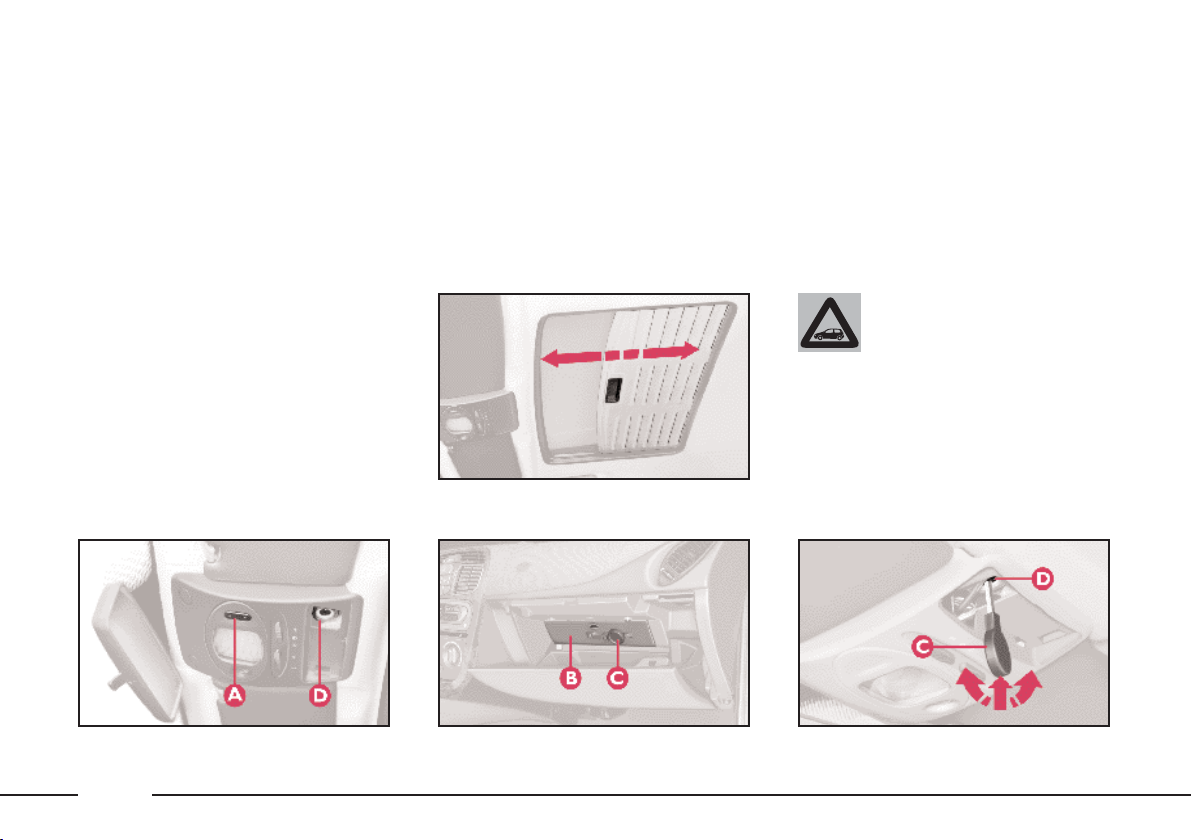
SUNROOF
The sunroof is electrically operated.
It will only work if the ignition key
is at MAR.
Button A (fig. 65) on the ceiling light
unit controls the opening, closing,
raising and lowering of the roof.
When you release the button, the
roof locks in the position it is in at
that moment.
£ Press once to open in the spoiler
position.
Press again to open completely.
¢ Press to close.
A sliding sunshade, fitted under the
sunroof, will lessen the effect of the
sun’s rays or the amount of air entering the car (fig. 66).
If there is an electrical fault in the
sunroof, open the glove compartment.
fig. 66
A key C (fig. 67) is attached to the
back of the cover B (fig. 67); insert
this key into D (fig. 68) and turn it to
manually perform the operations described previously (opening/closing).
To reach D, remove the press-fitted
cover.
Do not open the roof if
P4C00102
there is snow or ice on it as
you risk damaging it.
fig. 65
48
P4C00101
fig. 67
P4C00103
P4C00187
fig. 68
Page 52
Only open or close the
sunroof when the car is
stationary.
Incorrect use of the sunroof could be dangerous.
Before and when pressing
the switch, always make sure that
passengers are not liable to injury
either directly by the movement of
the sunroof or by personal effects
being dragged along or knocked
by the roof.
Always remove the ignition key when getting out
of the car to make sure
that the sunroof cannot be accidentally operated and constitute a
hazard for passengers remaining
in the car.
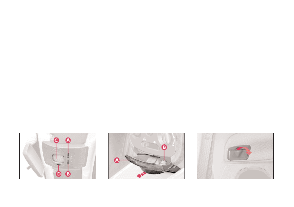
DOORS
SIDE DOORS CENTRAL
LOCKING/UNLOCKING
Unlocking from the outside
Insert the key into one of the two
doors and turn it to position 2
(fig. 69), then lift the door handle.
Before opening a door,
make sure that the conditions are safe to carry out
the manoeuvre.
Locking from the outside
Turn the key to position 1 (fig. 69).
Opening/locking the doors
from the inside
With the doors closed, press (to
lock) or lift (to unlock) the door opening lever A (fig. 70) on either the driver’s or the passenger’s side.
A green sector B (covered when the
lock is off) will appear when the door
is locked (lever A down). The instrument panel warning light ´may light
up if the doors are not closed perfectly
in some versions.
P4C00020
P4C00019
fig. 69
fig. 70
49
Page 53

IMPORTANT For versions with
door locking/unlocking remote control, see the “Lancia CODE system Door lock/unlock remote control”
paragraph at the beginning of this
chapter.
IMPORTANT If one of the doors is
not shut properly or there is a failure
in the system, the central locking feature will not work and, after some attempts, the device stops working for
around two minutes. In these two minutes the doors can be locked or unlocked manually without the electrical
system coming into play. After the two
minutes, the control unit is ready to
receive commands once more.
If the reason for the malfunction has
been removed, the device will start to
work properly again. If not, it will cut
out once more.
ELECTRIC WINDOWS
The electric windows are controlled
by two buttons situated in the inside
handle of the driver’s door (fig. 71).
They work when the ignition key is at
MAR:
A - left window;
B - right window.
Press the switch to open the window,
and pull it up to close it: this means
the window cannot be closed accidentally.
On the LX and 1.2
16V MMN red ver-
sions, if the driver’s window switch is
pressed for about one second, the window will work automatically: it will
stop when it is fully opened or closed
or when the switch is pressed again.
The door handle on the passenger
side has a button to control that particular window.
Incorrect use of the electric windows could be
dangerous. Before and
when pressing the switches, always
make sure that passengers are not
liable to injury either directly by
the movement of the windows or
by personal effects being dragged
along or knocked by the windows.
Always remove the ignition key
when getting out of the car to make
sure that the electric windows cannot be accidentally operated and
constitute a hazard for passengers
remaining in the car.
P4C00022
50
fig. 71
Page 54
BOOT
OPENING/CLOSING
THE TAILGATE
To open the boot from the outside,
unlock it with the ignition key A
(fig. 72).
To open it from inside the car, pull
lever A (fig. 73) at the side of the dri-
ver’s seat.
To lift the tailgate, use the grip located between the two number plate
lights.
Do not work boot release
lever when the car is in
motion.
When the tailgate is closed, it will
lock automatically, and can only be
reopened by using the key or pulling
lever A (fig. 73) inside the car.
IMPORTANT Never leave the keys
in the boot.
Use the handle situated in the interior trim of the tailgate A (fig. 74) to
lower it without getting your hands
dirty.
To close the tailgate, lower it and
press in the centre until you hear it
lock.
The addition of objects to
the rear parcel shelf or
tailgate (loudspeakers,
spoiler, etc.) may prevent the gasfilled struts at the sides of the tailgate working properly. Items
arranged on the rear window shelf
could be thrown forwards and injure passengers should you brake
sharply.
When using the boot,
make sure the load you are
carrying does not exceed
the permitted weight (see the
“Technical specifications” section). Also ensure the items in the
boot are arranged properly to prevent them being thrown forward
and injurying passengers should
you brake sharply.
fig. 72
P4C00021
fig. 73
P4C00015
P4C00037
fig. 74
51
Page 55
Heavy loads which are
not securely anchored
could seriously injure pas-
sengers in the event of an accident.
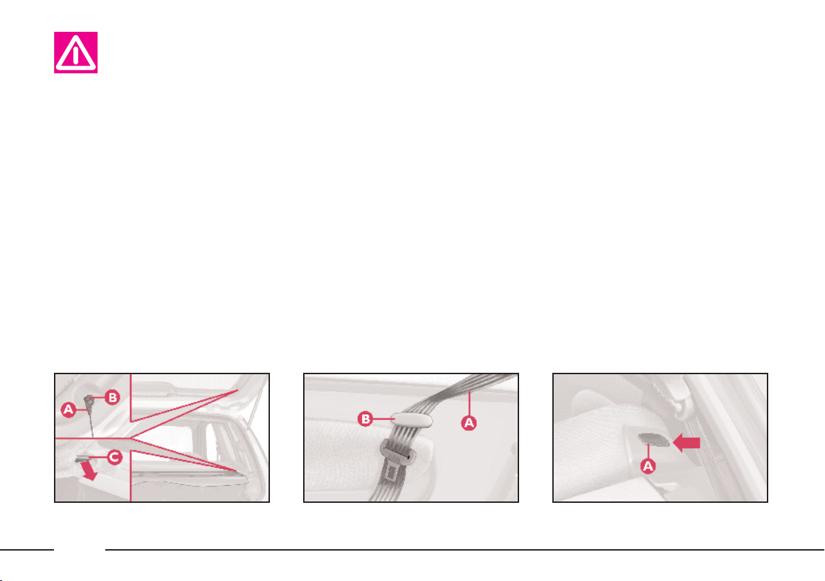
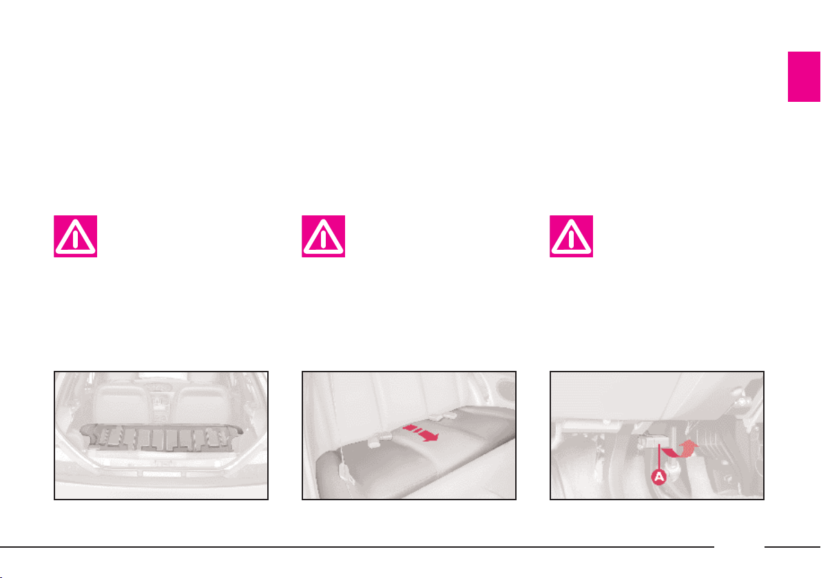
Removing the parcel shelf
If you wish to remove the parcel
shelf to extend the boot capacity, unhook the two tie-rods (one each side)
A (fig. 75) from the hooks B, then
pull the parcel shelf outwards so that
pins C come out.
The shelf can then be positioned behind the front seats.
INCREASING THE LOAD AREA
Proceed as follows:
1) Make sure that the side seat belts
A (fig. 76) have been inserted into the
corresponding bracket B.
2) Remove the rear head restraints
if required.
3) Release the seat back by pressing
button A (fig. 77) (one for each side)
located on the back seat back-rest
(even when a split back seat is fitted);
a red strip will appear on the short
side of the button (towards the inside
of the car) to indicate that it has been
released.
4) Fold the seat back forwards to
make a flat loading surface with the
boot floor (fig. 78).
If necessary, the cushion can also be
tilted (fig. 79). Consequently, before
releasing the seat back, lift the cushion as shown and tip it against the
front seat backs; the rear seat backrest can then be released and tilted
forwards.
To return the seat to its normal position:
1) Return the seat back to the vertical position and make sure it is properly locked into place; the red strip on
the hook-up button must disappear.
fig. 75
52
P4C00009
fig. 76
P4C00052
P4C00034
fig. 77
Page 56
2) Tip back the cushion while holding up the ends of the seat belts
(tongues and buckles) and passing
them between cushion and seat back.
In this way, the seat belts will be immediately ready to be used.
Some versions fit a split rear seat. In
this case, the left-hand side and the
right-hand side of the seat can be
tipped separately.
IMPORTANT When driving at
night with a load in the boot, adjust
the height of the dipped headlight
beam as shown in “Headlights” in
this chapter.
For correct adjustment, make sure
the load does not exceed the values indicated in the relevant section.
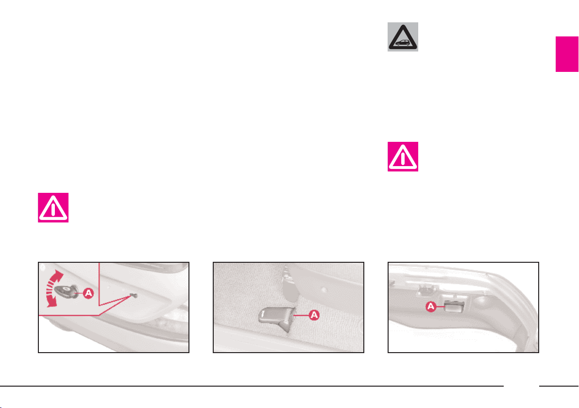
BONNET
To open the bonnet:
1) Pull lever A (fig. 80) (red) in the
direction of the arrow. This lever has
been positioned against the bulkhead
to prevent accidental opening.
If the backrest is not fastened properly, heavy
loose luggage behind it
could cause serious harm to passengers in the event of an accident.
fig. 78
If you wish to carry a reserve can of petrol, it is
important to comply to the
laws in force. Use only a homologated can and fasten it securely.
Even so, there is a greater fire risk
in the event of an accident.
P4C00160
fig. 79
This should be done only
when the car is stationary.
Before opening the bonnet, check the windscreen wiper
arms are not lifted from the windscreen.
P4C00051
fig. 80
P4C00001
53
Page 57

2) Lift lever B (fig. 81).
3) Lift the bonnet, and release the
support rod A (fig. 82) from its clip B.
4) Place the tip of the support rod in
recess C of the bonnet.
Scarves, ties and loose
garmets can get caught in
moving parts. This can be
extremely dangerous.
If repairs need to be carried out inside the engine
compartment when this is
still hot, be careful not to burn
yourself and keep away from the
electric fan as this may cut in at
any time, even if the key is removed from the ignition switch.
Wait until the engine has cooled.
Important. The bonnet
might fall violently if the
support rod is not posi-
tioned properly.
fig. 81
54
P4C00005
fig. 82
To close the bonnet:
P4C00006
1) Hold the bonnet up with one
hand and, with the other, remove rod
A (fig. 82) from recess C and replace
it in its clip B.
2) Lower the bonnet until it is about
20 cm (8 ins) above the engine compartment.
3) Let it fall: the bonnet closes automatically.
Always make sure the
bonnet is closed properly
so it will not open while
travelling.
Page 58

SKI AND
ROOF RACKS
ANCHORAGE HOOKS
POSITIONING
The hooks can be reached by slightly
moving the door seal in the points indicated in (fig. 83).
Fix the ski/roof rack attachments to
the front hook-up pins A.
The rear part of the ski/roof rack
should be attached to the edge of the
roof where the symbol Vis to be
found on the windows.
At this point, we should like to remind you that the Lineaccessori LANCIA range includes a ski/roof rack
that has been specifically designed for
the Lancia Y.
After travelling a few
miles, check the anchorage
bolts of the attachments
are still fully tightened.
Never load the rack with
more than the weight allowed (see the “Technical
specifications” section).
Take care not to knock
P4C00104
boot tailgate.
the objects on the roof
rack when opening the
HEADLIGHTS
CORRECT POSITIONING
OF THE HEADLIGHT BEAMS
The correct positioning of the headlight beams is very important for the
comfort and safety, not only of the
person driving the car, but also all
other road users.
This is also covered by a specific law.
To ensure you and other drivers
have the best visibility conditions
when travelling with the headlights
on, the headlights must be set properly.
Have the headlight position checked
at a LANCIA Dealership and ad-
justed if necessary.
fig. 83
55
Page 59
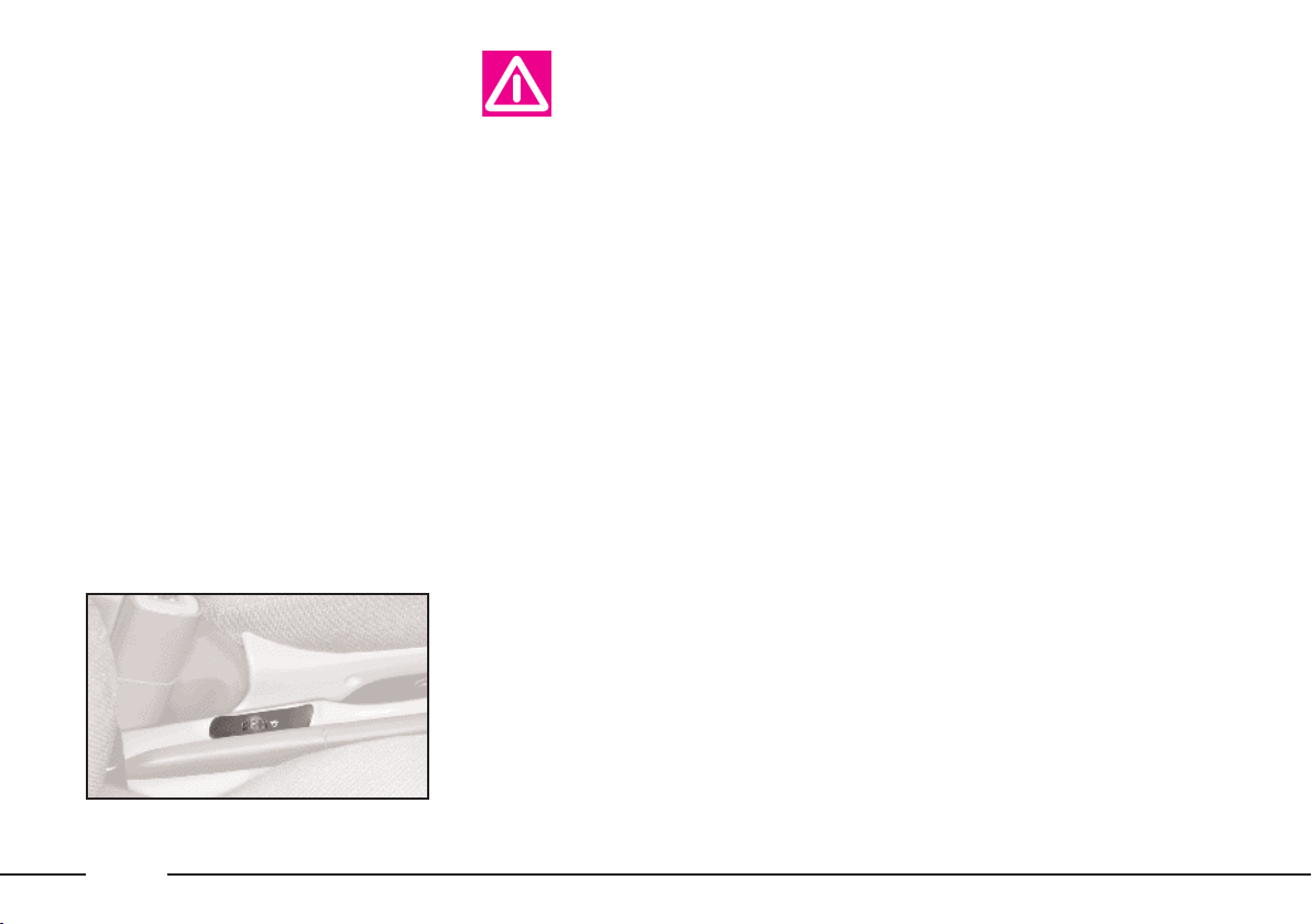
COMPENSATION
FOR THE UPWARD SLANT
OF THE HEADLIGHT BEAMS
When the car is loaded, it “slopes”
backwards. This means that the headlight beam rises. In this case it is necessary to return it to the correct position.
The car is fitted with an electric adjuster (fig. 84) situated at the side of
the handbrake:
Position 0 - one or two people on the
front seats.
Position 1 - five people.
Position 2 - five people + load in
luggage compartment.
Position 3 - driver + maximum permissible load all in the boot.
Check the positioning of
the headlight beams every
time you change the load
to be carried.
IMPORTANT In order that the ad-
juster operates properly, the load in
the boot must not exceed the maximum values indicated.
ADJUSTING THE BEAM
OF THE FRONT FOGLIGHTS
Ask a LANCIA Dealership to check
and, if necessary, adjust the beam for
you.
P4C00105
ABS
The car is fitted with an ABS braking system that prevents the wheels
locking when braking, it exploits the
grip on the road surface holding the
car in the case of sudden braking.
The driver becomes aware of the
ABS activation through a slight throbbing of the brake pedal and the relevant noise it makes.
This does not indicate brake malfunctioning, it is an indication to the
driver that the ABS is operating. It is
a warning that the car is travelling at
borderline road grip and therefore the
speed should be adjusted to the type
of road surface.
The ABS is an addition to the basic
braking system; in the case of a failure it disables, leaving the braking
system in the same conditions as a vehicle without ABS installed.
fig. 84
56
Page 60

In the case of failure, although the
anti-locking system is no longer available, the car braking capacity is not
interfered with.
If you have never driven a car with
ABS it is advised to familiarise by
making a few preliminary trials on
slippery ground, obviously maintaining safety conditions and respecting
the Highway Code of the country
where you are travelling. Before starting, read carefully the notes below.
The advantage of ABS as compared
with the traditional system is that it
permits maximum manoeuvrability
even when pressing the brakes right
down on roads with poor grip, preventing the wheels from locking.
However, this does not mean that
with ABS the braking distance is always reduced. For example, on soft
gravel surfaces or fresh snow on a
slippery surface the distance could increase.
In order to get the best out of the
anti-lock system when necessary, follow these hints.
ABS exploits the available grip, but it is not able
to increase it. Therefore
drive carefully on slippery surfaces
and do not take undue risks.
If the ABS triggers it
means that the car is
reaching the limit of ad-
herence between the tyres and the
road surface. Slow down to adapt
the speed to the road grip.
If there is a system fail-
ure, indicated by warning
light > lighting up on the
instrument panel, drive slowly and
go immediately to a LANCIA Dealership to have the system checked.
When braking round a bend be very
careful, even with the aid of ABS.
However, the most important advice
is the following:
When the ABS switches
on and you feel the pedal
throbbing, no not lighten
the pressure, but keep the pedal
pressed well down and do not
worry. In this way you will be able
to stop within the minimum distance possible, according to the
road surface.
Following these instructions you will
be always have the best braking conditions.
57
Page 61

IMPORTANT Cars fitted with ABS
must always be fitted with the wheel
rims, tyres and brake linings of the
type and make recommended by the
Manufacturer.
The system also includes the EBD
electronic brake correction (Electronic
Brake Distributor) which, through the
control unit and the ABS sensors further enhances the braking system.
The car is fitted with an
electronic brake distributor (EBD). If warning lights
> and x light up simultaneously
when the engine is running, this
indicates an EBD fault. This
means that violent braking could
cause early locking of the rear
wheels causing the car to skid.
Drive very carefully to the nearest
LANCIA Dealership to have the
system checked.
If only warning light >
switches on when the en-
gine is running, this usually indicates an ABS fault. In such
cases the braking system is still efficient, although the anti-locking
device does not function. The EBD
system may also be less efficient.
Go to a LANCIA Dealership immediately, taking care not to brake
suddenly, and have the system
checked.
If the x brake fluid low
warning light comes on,
stop the car immediately
and contact the nearest LANCIA
Dealership. Fluid leaks from the
hydraulic system, can compromise
brake system operation, both traditional systems and systems with
ABS.
FRONT AND SIDE
AIRBAGS
FRONT AIRBAGS (fig. 85)
Description and operation
The front airbag (driver and passenger) is a safety device which is immediately triggered in the event of a
front impact.
It consists of an instantly inflatable
bag housed in a special compartment
located:
– in the centre of the steering wheel
on the driver’s side;
– in the dashboard on the passenger’s side (larger bag).
The front airbag (driver and passenger) is a device which protects the
occupants of the car during a head-on
collision of a medium-high degree.
The system was designed to protect
from injury caused by the body crashing to the steering wheel or the dashboard.
58
Page 62
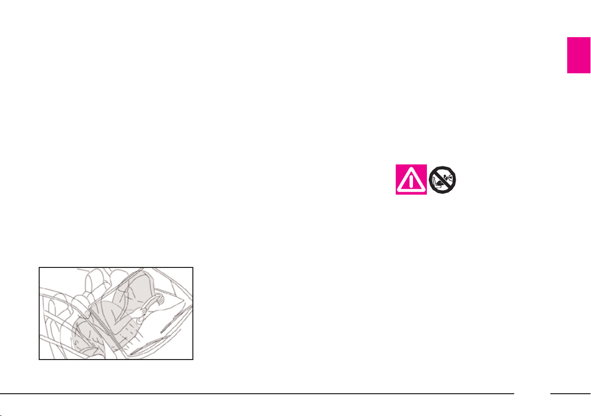
In a collision, an electronic control
unit processes the signals from a deceleration sensor and, where required,
inflates the airbag.
The bag inflates instantly and acts
as a soft protective barrier between
the front seat passengers and the
structures in front of them that could
cause injury. The bags deflate immediately afterwards.
A passenger not wearing the seat
belt may crash into the bag before it
is fully inflated. In this case, the protection is considerably decreased.
The airbag, as a consequence, is not
a replacement for the use of seat belts
but rather a complement. We recommend that seat belts are worn at all
times as prescribed by legislation in
fig. 85
Europe and most other countries
world-wide.
In the event of front collisions at low
speed, the restraining action of the
seat belts is sufficient and the airbag
is not inflated.
For impacts against very deformable
or mobile objects (traffic sign poles,
heaps of gravel or snow, parked vehicles), side impacts, wedging under
other vehicles or barriers (e.g. under
a truck or guard rail), the airbag is
not necessary and may even be undesirable.
The fact that the airbag is not triggered in these situations, this does not
signify a malfunction.
P4C00348
PASSENGER’S FRONT AIRBAG
The passenger side airbag was designed and calibrated to protect a person wearing seat belts.
When fully inflated, the bag will fill
most of the space between the dashboard and the passenger.
SEVERE DANGER:
if the car has a pas-
senger airbag, do
not place the child seat on the
front seat.
Manual deactivation
The passenger side airbag can be deactivated if it is absolutely necessary
to carry a child in the front passenger
seat.
Turn the specific switch A (fig. 86)
inside the glove compartment on the
left-hand side with the ignition key.
59
Page 63

The switch has two positions:
1) Passenger side airbag on: (position ON ) instrument panel warning light off. Do not carry children on
the front seat.
2) Passenger side airbag off: (position OFF ) instrument panel warning light on. A child can be carried on
the front seat with a suitable restraint
system.
The instrument panel warning light
will stay on until the passenger
side airbag is reactivated.
SIDE BAGS (fig. 87)
The purpose of the side bag fitted in
the seat is to protect the front seat
passengers in the event of a side impacts of medium to high degree.
The device consists of a bag housed
in the front seat backs which immediately inflates. This solution ensures
that the bag is in an optimal position
regardless of the seat position.
In the event of a side impact, the
control unit processes the signals from
a deceleration sensor and fires the side
bag.
The bag inflates instantly and acts
as a soft protective barrier between
the front seat passengers and car
door. The bags deflates immediately
afterwards.
In the event of side collisions at low
speed, the restraining action of the
seat belts is sufficient and the airbag
is not inflated. Also in this case, seat
belts should be worn at all times.
They ensure the passenger is correctly
positioned in the seat in the event of
side crash and prevent the passenger
from being projected from the vehicle
in the event of a very violent crash.
The airbag, as a consequence, is not
a replacement for the use of seat belts
but rather a complement. We recommend that seat belts are worn at all
times as prescribed by legislation in
Europe and most other countries
world-wide.
fig. 86
60
P4C00379
P4C00349
fig. 87
Page 64
GENERAL WARNINGS
The front and/or side airbags
(where fitted) can be triggered if
the car is subjected to considerable crashes or involved in an accident concerning the underbody
areas, such as a violent impact
against steps, kerbs or projecting
objects fastened to the ground,
falling into large holes or dips in
the road surface.
When the airbag is fired it emits
heat and a small amount of powder. This is not harmful and does
not indicate the beginning of a fire.
Furthermore, the surface of the inflated bag and in the passenger
compartment may be covered with
a powdery residues. This powder
may irritate skin and eyes. In the
event of exposure, wash with mild
soap and water.
Go to a LANCIA Dealership as
soon as possible if the warning
lightûcomes on when travelling
(to signal a fault) to have the problem repaired.
The airbag system is guaranteed
for ten years. Contact a LANCIA
Dealership as the expiry data approaches.
After an accident which triggered
the airbags, go to a LANCIA Dealership to have the entire safety system, the electronic control unit, the
seat belts and the pretensioners replaced. The Dealership will also
check the intactness of the electrical system.
Any diagnostic, repair or replacement operations concerning
the airbag system must exclusively
be carried out at a LANCIA Dealership.
If you are having the car
scrapped, have the airbag system
deactivated at a LANCIA Dealership first.
If the car changes hands, the new
owner must be made aware of the
indications given above and be
given this Owner Handbook.
The pretensioners (if electronically controlled), front airbags and
side airbags are activated by the
electronic control unit according
to the type of impact. Consequently, missed activation of one
or more system components does
not indicate a fault in the system.
The instrument panel
warning light û should
come on when the ignition
key is turned to MAR and go out
after approximately four seconds.
Immediately contact a LANCIA
Dealership if the warning light either does not come on or stays on
or comes on when travelling.
61
Page 65

When the passenger’s
front airbag is active (passenger front airbag deacti-
vation switch at ON), the warning light will come on for approximately four seconds and flash for
other four seconds when the ignition key is turned to MAR to remind the driver than the passenger’s front and side airbags (where
fitted) will be fired in the event of
a crash. The warning light should
go out immediately afterwards.
The airbag does not replace seat belts but rather
increases their effective-
ness. Furthermore, the airbag is
not fired in the event of low speed
front collisions, side collisions,
rear-end shunts and roll-overs. In
these cases, the passengers are
only protected by the seat belts
which for this reason must always
be fastened.
The correct operation of
front airbags, side airbags
and pretensioners is en-
sured only if the car is not overloaded. Do not exceed the maximum
permitted loads (see “Weights” in
“Technical specifications”).
It is important to remember that the airbag can be
fired even when the engine
is not running and the key is at
MAR if it is hit by another vehicle
travelling at suitable speed. As a
consequence, LANCIA recommends sitting children in their
specific restraint systems on the
back seat, which is the most protected position possible. On the
contrary, the airbags will not be
fired if the car is crashed into
when the key is not inserted or
turned. Consequently, in this case,
the fact that the system is not fired
does not indicate a fault.
Do not apply stickers or
other objects to the steering
wheel or to the dashboard
on the passenger’s side. Do not
travel with objects on your lap or in
front of you nor with a pipe, pencil
or similar between your lips; you
could seriously hurt yourself if the
airbag inflates in a collision.
Always drive with both
hands on the rim of the
steering wheel so that the
airbag is free to inflate during a
head-on collision, and protect you
from serious injury. Do not drive
with your body bending towards
the steering wheel, but sit in an
upright position with your back
resting against the seat.
If an attempt has been
made to steal the car, or if
it has actually been stolen
or has been vandalised in any way
or subjected to flooding, have the
airbag system checked over at a
LANCIA Dealership.
62
Page 66
The airbag does not replace seat belts but rather
increases their effective-
ness. Furthermore, the airbag is
not fired in the event of low speed
front collisions, side collisions,
rear-end shunts and roll-overs. In
these cases, the passengers are
only protected by the seat belts
which for this reason must always
be fastened.
Do not cover the seat
backs in cars with side
bags.
Do not wash the seat
back in cars with side
airbags with pressurised
steam or water in automatic seat
washing stations.
EOBD SYSTEM
The EOBD (European On Board Diagnosis) system fitted in this car complies with Directive 98/69/CE (EURO
3).
This system continuously monitors
the vehicle emission system components. Furthermore, the system warns
the driver of deterioration concerning
the emission system components by
means of the warning light on the
instrument panel.
The objective is to:
– monitor system efficiency;
– warn when failures can increase
emissions over the threshold established by the European regulations;
– warn of the need to replace deteriorated components.
Furthermore, the system is equipped
with a connector for interfacing with
specific tools used to read the error
codes stored in the control unit memory along with a set of diagnostic and
engine specific parameters.
Contact a LANCIA Dealership as soon as possible
if the warning light ei-
ther does not come on when the
key is turned to MAR or comes on,
with fixed or flashing light, when
travelling.
IMPORTANT After eliminating the
problem, your LANCIA Dealership
will run a bench test to fully check the
system. In some cases, a long road test
may be required.
63
Page 67
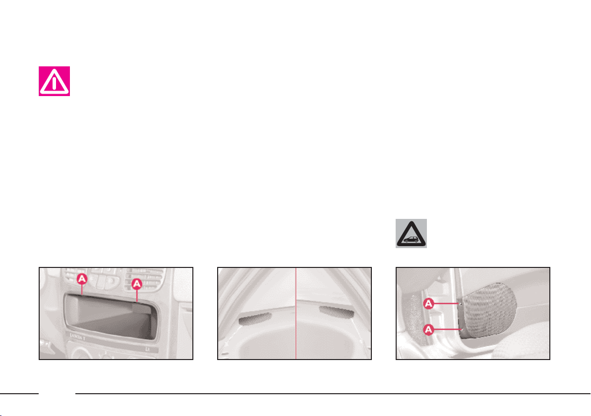
SOUND SYSTEM
Contact a LANCIA Dealership if you want to install a sound system after
purchasing your car. Their staff
will advise you on how to safeguard the life of the battery. Excessive idle intake can damage the
battery and invalid the battery
warranty as well.
STANDARD EQUIPMENT
All versions are fitted with the fol-
lowing:
– sound system power supply cables;
– cables for front speakers on dash-
board;
– sound system compartment;
– speaker compartments: front speakers on the dashboard and doors, rear
speakers on the side panels.
The sound system is installed in the
compartment normally occupied by
the object compartment, which can be
removed by pressing the two retaining tabs A (fig. 88).
You will find the power wires and
the wires connecting to the dashboard
speakers there.
The front tweeter speakers should be
housed in the compartments at the
sides of the dashboard (fig. 89):
– use a screwdriver with a fine blade
to lift the press-fitted grille; insert a
piece of adhesive tape between the
screwdriver and the dashboard to
avoid damaging the dashboard;
– to install the speakers in the doors,
unscrew the screws A (fig. 90) and remove the protective grille.
IMPORTANT If the sound system
has only two full-range speakers, use
the compartments in the doors. The
compartments in the dashboard
should only be used for the tweeters.
The rear speakers must be housed in
the compartments made in the side
panel trim (fig. 91). The protective
grille is inserted into place.
Go to a LANCIA Dealership to have the aerial wire
installed.
fig. 88
64
P4C00327
fig. 89
P4C00108
P4C00109
fig. 90
Page 68
BASIC SOUND SYSTEM optional
This consists of the following:
– 2 front tweeter speakers;
– 2 full-range speakers in the doors;
– rear speaker cables;
– wire and manual radio aerial lo-
cated on the front of the roof.
For electrical connections, see the section “Accessory installation”.
SOUND SYSTEM
The complete system consists of the
following:
– basic system (see previous para-
graph).
– Clarion PU2312 sound system
with CD player (fig. 92) (for characteristics and instructions see attached
supplement).
– case for front panel.
– brackets for removing radio unit.
– 2 rear speakers;
– CD CHANGER (where fitted) wire
with respecting connector located on
right-hand side of the boot, where you
can install a compatible CD
CHANGER if required.
RADIO-NAVIGATION
SYSTEM
The complete system consists of the
following:
– basic system (see previous para-
graph).
– Blaupunkt radio-navigator (fig. 93)
(for characteristics and instructions see
attached supplement).
– brackets for removing radio-navigator unit.
– 2 rear speakers.
– CD CHANGER wire with respecting connector located on right-hand
side of the boot, where you can install
a compatible CD CHANGER if required.
fig. 91
P4C00110
fig. 92
P4C00380
P4C00422
fig. 93
65
Page 69
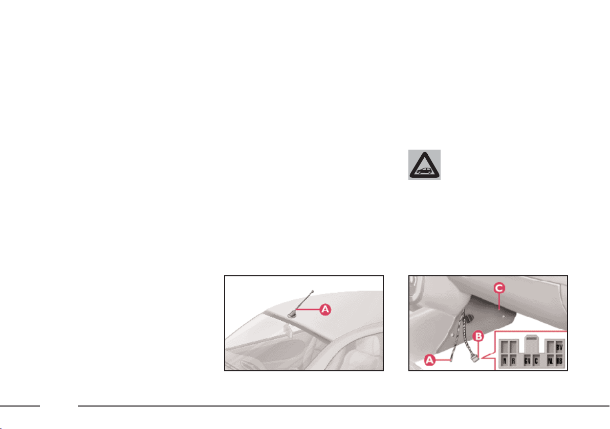
CELLULAR PHONE
SETUP
If the car has been ordered to include provision for the fitting of cellular phones, it will have:
– one dual purpose speaker (sound
system and cellular phone) located in
the right-hand door;
– one dual purpose aerial (sound
system and cellular phone) A (fig. 94)
located on the front part of the roof;
– cables to connect the dual purpose
aerial A (fig. 95) and a ten pin con-
nector B and cables to supply power
and to connect to the dual purpose
speaker located on the front part of
the central tunnel. To access the cables, remove the screws and flap C.
IMPORTANT Maximum applicable
power on the aerial is 20W.
The wiring diagram is:
N electronic earth.
R positive (+30), protected by
15A fuse no. 4 (in the interconnective fusebox, see the section “In an Emergency”).
GN light positive (+), protected by
10A fuse no. 10 (in the interconnective fusebox, see the section “In an emergency”).
C ignition switch positive (+),
protected by 15A fuse no. 3 (in
the interconnective fuse box,
see the section “In an emergency”).
NL dual purpose speaker on right
hand door (–).
RB dual purpose speaker on right
hand door (+).
BV sound system MUTE signal.
Install the microphone near the front
ceiling light so it does not interfere
with visibility when driving.
To install the cellular
phone and connect it to
this system, contact a LAN-
CIA Dealership.
P4C00303
P4C00361
66
fig. 94
fig. 95
Page 70
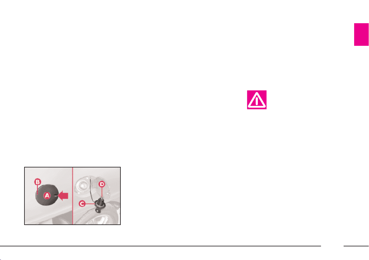
FUEL TANK CAP
Press the relief shown by the arrow
with your hand; flap A (fig. 96) will
open partially. Pull it out from rim B.
The cap is provided with a lock and
chain binding it to the body.
To open the fuel filler cap:
1) Hold the cap in position (still)
and turn the key anticlockwise.
2) Turn the cap approximately one
quarter of a turn anticlockwise and
remove it.
IMPORTANT The air-tight seal of
the cap may lead to a slight pressure
increase in the tank. A hissing sound
when the cap is removed is, therefore,
quite normal.
IMPORTANT To prevent the key
from being lost it cannot be removed
from the cap until the cap is put back.
3) When filling, position cap C on
hook D on the flap, as shown in the
illustration.
To close the fuel filler cap:
1) The cap is provided with a bayo-
net type lock. Position the cap (with
its key) and turn it clockwise until
you hear one or more clicks.
2) Turn the key clockwise and remove it. Close the flap.
P4C00381
Only change the fuel filler cap with
a genuine spare part in order not to
compromise the petrol fume recovery
system.
Do not put naked flames
or lighted cigarettes near
the fuel filler hole as there
is a danger of fire. Do not bend too
close to the hole either so as not to
breathe in harmful vapours.
fig. 96
67
Page 71

DRIVING YOUR CAR
To help you handle your car in the best and
safest possible way, and above all use it to its fullest
potential, we have given you some hints in this
chapter on “what to do, what not to do and what
to avoid” when at the wheel of your Lancia Y.
Most of the time, these suggestions apply to
other cars as well. Sometimes, however, the tip
may apply to an exclusive Lancia Y feature. You
are therefore strongly recommended to pay the
closest attention to this section for helpful hints
on optimum driving practices and usage of the car
that will help you get the most out of your car.
STARTING THE ENGINE .............................. 69
PARKING ....................................................... 71
GEAR USE ..................................................... 72
AT THE FILLING STATION .......................... 73
SAFE DRIVING .............................................. 75
CONTAINING RUNNING COSTS
AND POLLUTION ......................................... 81
CHEAP RUNNING THAT RESPECTS
THE ENVIRONMENT ................................... 83
TOWING A TRAILER .................................... 84
SNOW CHAINS .............................................. 85
SNOW TYRES ................................................ 86
STORING THE CAR ...................................... 87
REPEATED CHECKS AND CHECKS
BEFORE LONG TRIPS .................................. 88
ACCESSORIES PURCHASED
BY THE OWNER ........................................... 88
USEFUL ACCESSORIES ............................... 89
68
Page 72
STARTING
THE ENGINE
It is dangerous to let the
engine run in a garage or
other closed area. The en-
gine consumes oxygen and gives
off carbon dioxide, carbon monoxide and other poisonous fumes.
The ignition switch fits a safety device. If the engine does not start at the
first attempt, return the ignition key
to STOP before trying to start the engine again.
In a similar way, you will not be able
to turn the key from MAR to AVV
when the engine is running.
PROCEDURE
IMPORTANT Do not press on the
accelerator before the engine is running.
1) Make sure the handbrake is up.
2) Put the gear lever into neutral.
3) Press the clutch pedal down to the
floor.
4) Turn the ignition key to AVV and
let it go the moment the engine starts.
Do not touch the high
voltage cables (spark plug
cables) when the engine is
running.
If the engine does not start at the
first attempt, return the ignition key
to STOP before trying to start the engine again.
If warning light ¢ remains lit together with the warning light
when the ignition key is at MAR,
turn the key to STOP and then to
MAR; if the warning light still remains lit, try with the other keys provided with the car.
If you are still unable to start the engine, follow the emergency startup
procedure (see “Emergency startup”
in the section “In an emergency”) and
go to the nearest LANCIA Dealer-
ship immediately.
IMPORTANT Do not leave the ig-
nition key at MAR when the engine is
off.
During the running-in
period do not push the car
up to its highest perfor-
mance (e.g. sudden accelerations,
very long drives at high speed,
sharp braking etc.)
69
Page 73

HOW TO WARM UP
THE ENGINE AFTER
IT HAS JUST STARTED
– Begin to move forward slowly letting the engine turn over at medium
revs. Do not accelerate abruptly.
– Do not push the engine to its limit
for the first few kilometres. You are
recommended to wait until the water
temperature has reached 50°C to
60°C (pointer moves slightly from its
initial position).
EMERGENCY STARTING
If the Lancia CODE system fails to
recognise the code transmitted by the
ignition key (warning lamp ¢ on instrument panel lit with a fixed light),
you can start the engine by following
the emergency procedure using the
code written on the CODE card.
See the section “In an emergency”.
BUMP STARTING
Bump starting by pushing, towing or rolling
downhill must be avoided
at all costs. This way of starting
could cause a rush of fuel into the
catalytic exhaust pipe and damage
it beyond repair.
Remember that as long as
the engine is not running,
the brake booster and
power steering do not work. You
therefore have to use considerably
more effort on both the brake
pedal and the steering wheel.
STOPPING THE ENGINE
Turn the ignition key to STOP while
the engine is idling.
A quick burst on the accelerator before turning off
the engine serves ab-
solutely no practical purpose, and
wastes fuel.
IMPORTANT After a taxing drive it
is better to allow the engine to “catch
its breath” before turning it off by letting it idle to allow the temperature in
the engine compartment to fall.
70
Page 74

PARKING
Stop the engine, engage the handbrake and engage a gear (first gear if
the car is faced uphill or reverse if it
is faced downhill). Leave the wheels
steered. Block the wheels with a
wedge or a stone if the car is parked
on a steep slope.
If the car is parked on a steep slope,
block the wheels with a wedge or a
stone.
Do not leave the ignition key at
MAR because it drains the battery.
Always remove the key when you
leave the car even if it is only for a few
moments.
Do not leave children un-
supervised in the car.
HANDBRAKE
The handbrake lever is situated be-
tween the two front seats.
To put the handbrake on, pull it upwards until the vehicle is blocked;
normally four or five clicks are sufficient on flat ground, whereas seven or
eight might be necessary when parking on steep slopes with the vehicle
laden.
IMPORTANT If this is not the case,
take the car to a LANCIA Dealer-
ship to have the handbrake adjusted.
When the ignition key is turned to
MAR and the handbrake pulled up,
the warning lamp x will light up on
the instrument panel.
To release the handbrake:
1) Slightly lift the handbrake and
press release button A (fig. 1).
2) Keep the button pressed in and
lower the lever. Instrument panel
warning light x will go out.
3) To prevent accidental movement
of the car, when releasing the handbrake, keep the foot brake depressed.
P4C00113
fig. 1
71
Page 75
GEAR USE
To engage the gears, press down the
clutch and put the gear lever into one
of the positions shown in the diagram
(fig. 2) (the diagram is also on the
gear lever knob).
To engage reverse (R), wait for the
car to come to a standstill. From neutral, lift the sliding ring A (fig. 2) un-
der the knob and shift the lever to the
right and backwards at the same
time.
IMPORTANT The reverse gear can
only be engaged when the car is stationary. With the engine running wait
for at least 2 seconds with the clutch
fully down before engaging the reverse gear to avoid grating the gears
and damaging them.
P4C00346
To change gear properly
you must push the clutch
pedal fully down. It is
therefore essential that there is
nothing under the pedals: make
sure mats are lying flat and do not
get in the way of the pedals.
Do not drive with your
hand resting on the gear
lever. Although the force
you exert by doing this is very
slight, it will, in the long run, wear
out the components inside the
gearbox.
fig. 2
72
Page 76

AT THE FILLING
STATION
FUEL
Fill petrol engine cars only with unleaded petrol with a minimum octane
number of 95.
Fuel tank capacity: 45 litres including a reserve of 5 - 8 litres.
An inefficient catalytic
converter will allow harmful exhaust fumes to be
emitted and thus contribute to the
pollution of the air.
Never put even the tiniest
amount of leaded fuel in
the tank, even in an emer-
gency. You would damage the catalytic converter beyond repair.
ENGINE OIL
Check the level: see the “Car main-
tenance” section.
The distance between the MIN and
MAX marks on the dipstick is equivalent to about one litre of oil.
Use SAE 10W-40 oil for temperatures down to –25°C.
For temperatures lower than –20°C,
we recommend using SELENIA
PERFORMER SAE 5W-30.
P4C00399
Refer to the “Technical specifica-
tions” section for other information.
SPARK PLUGS
1.2 versions:
– Champion ................... RC10YCC
– NGK ............................. BKR5EZ
1.2
16V versions:
– NGK ......................... DCPR8E-N
ENGINE COOLANT
Top up with a 50% mixture of water and PARAFLU11. For other data,
refer to the “Technical specifications”
section.
fig. 3
73
Page 77

LIGHT BULBS
Dipped beam headlights: 12V-55W.
Main beam headlights: 12V-55W.
Side and taillights: 12V-5W.
Front foglights: 12V-55W.
Front direction indicators: 12V-21W.
Rear direction indicators: 12V-21W.
Side direction indicators: 12V-5W.
Stop/taillights: 12V-21/5W.
Reversing lights: 12V-21W.
Rear foglights: 12V-21W.
Number plate lights: 12V-5W.
Ceiling lights: 12V-10W.
Map reading light: 12V-6W
(LX version).
Boot light: 12V-10W.
Third brake lights: 12V-5W.
TYRE INFLATION PRESSURE
WHEN COLD (bar)
When the tyre is warm the pressure
must be 0.3 bar higher than the specified value.
Tyre
16V MN blue - 1.2 LS -
1.2
1.2 16V LS
1.2
16V LX
16V MN red
1.2
Snow tyre: 165/65 R14 78Q (M+S) 2.2 2.2 2.2 2.2 2.8
- for all versions 185/60 R14 82Q (M+S) 2.0 1.9 2.2 2.2 2.8
Snow tyre:
- for 1.2
* Snow chains cannot be fitted on these tyres.
16V MN red version
165/65 R14 78T
185/60 R14 82H 2.0 1.9 2.2 2.2 2.8
185/60 R14 82T
185/60 R14 82H
185/60 R14 82T
195/50 R15 82H* 2.4 2.2 2.4 2.2 2.8
185/60 R14 82H
165/65 R14 78Q (M+S) 2.2 2.2 2.2 2.2 2.8
185/60 R14 82Q (M+S) 2.0 1.9 2.2 2.2 2.8
195/50 R15 82H 2.4 2.2 2.4 2.2 2.8
▲
▲
Average load
Front Rear Front Rear
2.0 1.9 2.2 2.2 2.8
2.0 1.9 2.2 2.2 2.8
Alternative tyres.
Fully laden Spare wheel
74
Page 78

SAFE DRIVING
In designing the Lancia Y, we made
every effort to come up with a car
able to provide driver and passengers
with top-class levels of safety. Nevertheless it is always the behaviour of
the person at the wheel that determines road safety.
Below you will find some simple tips
to help you travel in safety under different conditions. You will no doubt
be familiar with many of them already but it will be useful to read
them all carefully.
BEFORE GETTING BEHIND
THE WHEEL
– Make sure all lights including the
headlights are working properly.
– Adjust the position of the seats,
steering wheel, driving and door mirrors properly for the best driving position.
– On long journeys, it is a good idea
to slightly alter the lumber support
and/or seat inclination to vary the
weight on the spine and therefore reduce tiredness and strain.
– Carefully adjust the head restraints
so the back of the head and not the
nape of the neck is supported.
– Carefully adjust the height of the
seat belts to suit the wearer’s stature
(see the instructions given in the section “Getting to know your car - seat
belts”).
– Make sure that nothing (mats etc.)
get in the way of the pedals.
– Make sure that any child restraint
systems (child seats, carriers, etc.) are
properly fixed to the rear seat. Follow
the indications given in “Transporting children safely” in the section
“Getting to know your car”.
– Make sure that objects are carefully arranged in the boot so they will
not fly forward if you have to brake
sharply.
– Avord placing light-coloured articles or papers on the object tray which
may be reflected on the windscreen.
– Do not eat a heavy meal before
travelling. Light eating will help keep
your reflexes prompt. Above all, do
not have anything alcoholic to drink.
The use of some drugs may affect
your driving, read the relevant instructions sheet carefully.
Remember to periodically check
what is specified in the “Repeated
checks and checks before long trips”
paragraph given in this section.
75
Page 79

Consider the space required by extra mats: even
a small problem to the
braking system may indicate additional brake pedal stroke is required with respect to normal.
Water, ice and salt sprinkled on the road deposit
on the brake disc and re-
duce effectiveness the first time
you brake.
Pay attention when installing additional spoilers, alloy wheel rims and
caps that are not standard. They
could reduce the brake ventilation
and as a consequence, the braking
efficiency if you brake suddenly
and repeatedly, or when driving
downhill.
WHEN TRAVELLING
– The first rule of safe driving is pru-
dence.
– Prudence also means putting yourself into a position where you can predict wrong or imprudent behaviour
from other drivers.
– Stick closely to the rules of the
road in the particular country where
the car is being driven and, above all,
do not exceed speed limits.
– Ensure that, besides yourself, all
the other passengers in the car have
their seat belts fastened, that children
are sitting in the appropriate child
seats and any animals are in special
compartments.
– You should be physically fit and
mentally alert before setting out on
long journeys.
Driving when you are not
mentally alert, drunk, under the influence of drugs
or certain medicines is dangerous
both for you and other road users.
Always fasten both front
and back seat belts including child seat seat belt
if fitted. Travelling with the seat
belts unfastened increases the risk
of injury or death if you are in a
collision.
Do not drive with objects
on the floor in front of the
driver’s seat. Objects
could get stuck under the pedals
making accelerating and braking
impossible.
76
Page 80

– Do not drive too many hours at a
time but stop at intervals to stretch
your legs and recover your energies.
– Make sure the air in the car is being changed continuously.
– Never coast downhill (i.e. with the
engine off): if you do, you lose the aid
of engine brake, power brakes and
power steering so that braking and
steering require greater effort.
– Never coast downhill (i.e. with the
engine off): if you do, you lose the aid
of engine braking and power.
DRIVING AT NIGHT
If you are driving at night these are
the main rules to follow:
– Drive especially carefully: it is
harder to drive at night.
– Slow down especially if the road is
not lit.
– At the first signs of sleepiness, stop:
continuing would be a risk for yourself and everybody else. Only start
driving again when you have had
enough rest.
– Keep a greater safety distance
from the cars in front of you than
during daylight hours: it is hard to
judge how fast other cars are going
when all you can see are their lights.
– Make sure the headlight beams are
properly positioned: if they are too
low, they reduce visibility and strain
your eyes. If they are too high they
can dazzle other drivers.
– Only use main-beam headlights
when you are driving outside town
and when you are sure they do not
annoy other drivers.
– Dip your headlights (if on) as soon
as you see cars coming in the other direction and pass them with the headlights dipped.
– Keep all lights clean.
– Be careful of animals crossing the
road when driving in the country.
DRIVING IN THE RAIN
Rain and wet road surfaces spell
danger.
All manoeuvres are more difficult on
a wet road because the grip of the
wheels on the tarmac is greatly reduced. This is why braking distances
are much longer and roadholding is
lower.
77
Page 81

Here is some advice for driving in
the rain:
– Reduce speed and maintain a
greater safety distance from the cars
in front.
– If it is raining particularly heavily,
visibility is also reduced. In these
cases, switch on the dipped headlights
even if it is still daylight so you can be
seen more easily.
– Do not drive through puddles at
speed and hold on tightly to the
wheel: a puddle taken at high speed
might cause you to lose control of the
car (“aquaplaning”).
– Move the ventilation controls to
the position for demisting the windows (see the section “Getting to
know your car”), to avoid visibility
problems.
– Periodically check the condition of
the windscreen wiper blades.
DRIVING IN FOG
– If the fog is thick, do not start out
on a journey unless you absolutely
have to.
If driving in mist, blanket fog or
when there is the danger of fog
patches:
– Keep your speed down.
– Turn on the dipped headlights,
rear foglights and front foglights, if
fitted, even during the day. Do not
drive with your headlights at fullbeam.
– Remember that fog also means the
tarmac is wet and therefore manoeuvres of all kinds are more difficult and
stopping distances are longer.
– Keep a good distance from the cars
in front of you.
– As far as possible, avoid spurts of
speed or sudden deceleration.
– Do not overtake other vehicles if
you can help it.
– If you are forced to stop your car
(breakdown, limited visibility etc.)
try to stop off the road. Turn on the
hazard lights and, if possible, the
dipped headlights. Rhythmically
sound the horn if you realise another
car is coming.
IMPORTANT On stretches of road
with good visibility, switch off your
rear foglights; the brightness of these
lights could annoy the people travelling in the cars behind.
78
Page 82

DRIVING IN THE MOUNTAINS
– When driving downhill use the engine braking effect by engaging a low
gear so as not to overheat the brakes.
– Under no circumstances should
you drive downhill with the engine off
or with the car in neutral, let alone
with the ignition key out.
– Drive at a moderate speed without
cutting corners.
– Remember that overtaking while
going uphill is slower and therefore requires more free road. If you are being
overtaken while driving uphill, make
it easier for the other vehicle to pass.
DRIVING ON SNOW OR ICE
Here are some tips for driving in
these conditions.
– Before starting off, check that the
windscreen wiper blades are not stuck
to the windscreen.
– Remove any snow from the climate
control system air intake.
– Keep your speed down.
– Use chains or snow tyres if the
roads are covered in snow, see the respective paragraphs in this chapter.
– Do not keep the engine running for
long periods in deep snow as the snow
could push exhaust gases into the passenger compartment.
– Mainly use the braking effect of
the engine and under all circumstances avoid braking sharply.
– When braking in a car not fitted
with ABS, avoid the wheels locking by
varying the pressure you exert on the
brake pedal.
– Do not accelerate suddenly and
avoid swerving.
– In the winter, even apparently dry
roads may have icy patches. Be careful therefore when driving over
stretches that do not get much exposure to the sun or that are lined by
trees and rocks, where ice might not
have melted.
– Keep a good distance from the vehicles in front.
79
Page 83
DRIVING WITH ABS
The car can be fitted with a wheel
anti-locking system (ABS) and with
electronic brake correction (EBD) system.
ABS is a braking system that essentially offers two advantages:
1) It prevents wheel locking and
consequent skidding in emergency
stops, particularly when the road does
not offer much grip.
2) It makes it possible to brake and
steer at the same time so you can
avoid unexpected obstacles and direct
the car where you want while braking. The extent to which this can be
done will depend on the physical limits of the tyre’s total grip.
To get the most out of ABS:
– During emergency stops or when
grip conditions are poor, you will feel
a slight pulsation on the brake pedal.
This is the sign that the ABS is working. Do not release the brake pedal
but continue to press so as not to interrupt the braking action.
– ABS prevents the wheels from
locking, but it does not increase actual grip conditions between tyre and
road. Therefore, even if your car is fitted with ABS, respect the safety distance from the car in front of you and
keep your speed down when driving
into bends.
ABS serves to increase the controllability of the car, not to enable you to
go faster.
If warning light >
switches on when the en-
gine is running, this usually indicates an ABS fault. In such
cases the braking system is still efficient, although the anti-locking
device does not function. The EBD
system may also be less efficient.
Go to a LANCIA Dealership immediately, taking care not to brake
suddenly, and have the system
checked.
The car is fitted with an
electronic brake corrector
(EBD). If warning lights >
and x light up simultaneously
when the engine is running, this
indicates an EBD fault. This
means that violent braking could
cause early locking of the rear
wheels causing the car to skid.
Drive the car extremely carefully
to the nearest LANCIA Dealership
to have the system checked.
80
Page 84

CONTAINING
RUNNING COSTS
AND POLLUTION
Some suggestions which may help
you to keep the running costs of your
car down and lower the amount of
toxic emissions released into the atmosphere are given below.
GENERAL CONSIDERATIONS
Car maintenance
The overall state of the car is an important factor which has a marked influence over fuel consumption and
driving comfort and on the life span
of your car. For this reason care
should be taken to maintain your vehicle by carrying out the necessary
checks and regulations in accordance
with the specifications given in the
Servize Schedule (see spark plugs,
idle, air filters, timing sections).
Tyres
Tyres should be checked at least
every four weeks: if the pressure is too
low fuel consumption increases as the
resistance to the rolling movement of
the tyre is greater. In this state, tyre
wear is increased and car handling
suffers which will affect safety.
Unnecessary loads
Do not travel with too much luggage
stowed in the boot. The weight of the
car (especially when driving in town)
and its trim greatly affects consumption and stability.
Roof/ski racks
Remove roof or ski racks from the
roof of the car as soon as they are no
longer needed. These accessories reduce the aerodynamic penetration of
the car and will increase consumption. When transporting particularly
large objects, use a trailer where possible.
Electrical devices
Use the electrical devices for the necessary time only. The heated rear window, supplementary lights, windscreen wipers, heating system blower
require large amounts of energy and,
increasing the request for power also
increases fuel consumption (up to
+25% when driving in built-up areas).
Air conditioner
The air conditioner is an additional
load which greatly affects the engine
leading to higher consumption (on average up to +20%). When the temperature outside the car permits it,
use the air vents where possible.
Spoilers
The use of aerodynamic optional extras which are not certified for specific
use on the car, may reduce the aerodynamic penetration of the car and
increase consumption.
81
Page 85

STYLE OF DRIVING
Starting
Do not warm the engine when the
car is stationery or at high or low revs:
in this way the engine will warm up
gradually increasing consumption and
emissions. You should drive off slowly
straight away avoiding high revs so
that the engine will warm up more
quickly.
Unnecessary actions
Avoid revving the engine when
stopped at traffic lights or before
switching off the engine and avoid
doubling the clutch as these actions
have no purpose on modern vehicles
and serve only to increase consumption and pollution.
Gear selection
As soon as the traffic and road conditions allow it, shift to a higher gear.
Using a lower gear to liven up acceleration greatly increases consumption.
In the same way, improper use of the
higher gears will increase consumption, emissions and wear and tear on
the engine.
Top speeds
Fuel consumption increases considerably as speed increases. For example, when accelerating from 90 to
120 kph, fuel consumption increases
by about +30%. Your speed should
be kept as even as possible and superfluous braking and acceleration
avoided as this increases both consumption and emissions. A “soft” way
of driving should be adopted by attempting to anticipate manoeuvres to
avoid imminent danger and to keep a
safe distance from the vehicle in front
in order to avoid braking sharply.
Acceleration
Accelerating violently increasing the
revs will greatly affect consumption
and emissions: acceleration should be
gradual and not exceed the maximum
torque.
CONDITIONS OF USE
Cold starting
Frequent cold starting will not enable the engine to reach optimal running temperature. It follows therefore
that consumption will be higher (from
+15% to +30% in built-up areas) as
will the production of toxic emissions.
82
Page 86

Traffic and road conditions
Heavy traffic and higher consumption are synonymous; for example,
when driving slowly with frequent use
of the lower gears or in large towns
where there are numerous traffic
lights.
Winding roads, mountain roads and
bumpy roads also have a negative effect on consumption.
Enforced halts
During prolonged hold-ups (traffic
lights, level crossings) the engine
should be switched off.
CHEAP RUNNING
THAT RESPECTS
THE ENVIRONMENT
Environmental protection has been
one of the guiding principles in the
production of the Lancia Y. It is no accident that its pollution control equipment is much more effective than that
required by current legislation.
Nonetheless, the environment cannot get by without a concerted effort
from everyone.
By following a few simple rules you
can avoid harming the environment
and often cut down fuel consumption
at the same time.
On this subject, a few useful tips
have been given below to supplement
those marked by symbol # at various
points of the handbook.
You are asked to read both the former and latter carefully.
LOOKING AFTER EMISSION
CONTROL DEVICES
The correct use of pollution control
devices not only ensures respect for
the environment but also has an effect
on the car’s performance. Keeping
these devices in good condition is
therefore a fundamental rule for driving that is easy on your pocket and
on the environment too.
The first step to take is to follow the
Service Schedule to the letter.
Use only unleaded petrol.
If you have trouble starting, do not
keep turning the ignition key for long
periods. Be especially careful to avoid
bump starting the car by pushing,
towing or rolling down hill: these are
all manoeuvres that can damage the
catalytic exhaust.
83
Page 87

For emergency starts use only an
auxiliary battery.
If the engine begins to “loose its
smoothness” when travelling, continue your journey but reduce the demands you are making on the engine
and have the car seen to at a LANCIA
Dealership as soon as you can.
When the instrument panel fuel reserve warning light comes on, fill up
as soon as possible. A low level of fuel
can cause an uneven supply of fuel to
the engine with the inevitable increase
in the temperature of the exhaust gas
and serious damage to the catalytic
converter.
Never run the engine with one or
more spark plugs disconnected, even
for testing purposes.
Do not warm up the engine by letting it idle for a while before moving
off unless the outside temperature is
very low and, even in this case, only
do so for less than thirty seconds.
Do not install other heat shields and
do not remove those already fitted to
the catalytic converter and exhaust
pipe.
Do not allow anything to be sprayed
onto the catalytic converter, Lambda
sensor and exhaust pipe.
When functioning normally the catalytic converter reaches high tem-
peratures. For this reason do not
park the car over inflammable
material (grass, dry leaves, pine
needles etc.): fire hazard.
Failure to heed these precautions could cause a
fire.
TOWING A TRAILER
IMPORTANT The car must be fitted with a homologated tow hitch and
suitable electrical system for towing a
caravan or trailer.
Have the tow hitch fitted by an expert who will issue specific documentation for use on roads.
Fit special and/or additional
rearview mirrors in accordance with
the highway code.
Remember that towing a trailer
makes it harder for the car to climb
the maximum gradients specified.
Engage a low gear when driving
downhill rather than constantly braking.
84
Page 88

The weight the trailer exerts on the
car’s tow hitch coupling reduces the
car’s carrying capacity by the same
amount.
In order to be sure you are not exceeding the maximum towing weight
(given on the car’s registration papers), you have to take into account
the trailer’s weight fully laden including the accessories and personal
luggage.
Do not exceed the speed limits for
towing a trailer in the country you are
driving in. In any case, do not exceed
the top speed of 100 km/h.
The ABS system with
which the car may be fitted
does not control the brak-
ing system of a trailer. Special care
must therefore be taken on slippery surfaces.
Under no circumstances
modify the car’s braking
system for trailer braking
control. The trailer’s braking system must be completely independent of the car’s hydraulic system.
SNOW CHAINS
The use of snow chains is regulated
by the legislation in force in the country the car is driven in.
The chains may only be applied to
the drive wheel tyres (front wheels).
Use only low profile chains (maximum height off the tyre: 12 mm).
Check the tautness of the chains after driving some twenty to thirty metres.
IMPORTANT As the spare wheel is
small (space-saver), it is not possible
to fit snow chains to it. If a front tyre
is punctured, first exchange a rear
wheel with the spare tyre and then
change the flat tyre with the rear wheel
thus removed. This way there will be
two ordinary wheels at the front and
the snow chains can be fitted.
Remember that the wheels should
always be exchanged on the same side
of the vehicle; never change wheels
over from one side of the car to the
other.
85
Page 89
Keep you speed
down when snow
#
Avoid potholes, steps and kerbs.
Do not drive for long distances on
roads free from snow as not to
damage the car and the road surface.
fitted with 195/50 R15 82H
tyres; snow chains cannot
be fitted on these tyres. Alternatively, have 185/60 R14 82H tyres
fitted on which snow chains can be
mounted. If it is desired to use
snow tyres see the section “Snow
tyres”.
chains are fitted.
The 1.2 16V MN red car is
SNOW TYRES
These are tyres that have been
specifically designed for driving on
snow and ice, to be fitted in place of
the car’s standard tyres.
Only replace with the type of tyre indicated in the table below:
Standard tyre Snow tyre
165/65 R14 78T
185/60 R14 82H
185/60 R14 82T
195/50 R15 82H
(*) See the warnings concerning maximum speed on the next page.
165/65 R14 78Q (M+S) (*)
185/60 R14 82Q (M+S) (*)
195/50 R15 82H
LANCIA Dealership is pleased to
offer advice concerning the choice of
the most suitable tyre according to the
use required by the Customer.
Refer to the pressure of standard
tyres of the same size to find the correct inflation pressure: see “Tyre pressure” in the “Technical Specifications” section.
The winter characteristics for snow
tyres are considerably less when the
tread is less than 4 mm. In such cases
it is safer to replace them.
The snow tyre characteristics are
such that, with normal environmental conditions or on long journeys on
the motorway their performance is
lower than that of standard tyres.
86
Page 90

Therefore they should only be used
for the purpose for which they have
been homologated (“Q” indicates that
the tyre is designed for a speed of less
than 160 km/h).
IMPORTANT When using snow
tyres with a maximum speed index
that is less than the capacity of the car
(increased by 5%), place in the passenger compartment, well in sight, a
warning that indicates the maximum
speed permitted by the snow tyres (in
accordance with the EC Directive).
Fit four identical tyres (same make
and tread) on the wheels to ensure
safety when driving and when braking as well as easy handling.
Do not reverse the direction of rotation of the tyres.
The maximum speed of
snow tyres with a “Q” indication must never ex-
ceed 160 km/h and in any case
must always observe the regulations of the Highway Code.
STORING THE CAR
Do the following if the car is not to
be used for more than a month:
– Park the car in covered, dry and if
possible well-ventilated premises.
– Engage a gear.
– Remove the cables from the battery terminals (first remove the cable
to the negative terminal) and check
the battery charge. This check should
be carried out once every three
months while the car is in storage.
Recharge the battery if the no-load
voltage is less than 12.5V.
– Make sure the handbrake is not
engaged.
– Clean and protect the painted
parts using protective wax.
87
Page 91

– Clean and protect the shiny metal
parts using special compounds available on the market.
– Sprinkle talcum powder on the
rubber windscreen and rear window
wiper blades and lift them off the
glass.
– Slightly open the windows.
– Cover the car with a cloth or perforated plastic sheet. Do not use
sheets of imperforated plastic as they
do not allow moisture on the car body
to evaporate.
– Inflate the tyres to 0.5 bar above
the normal specified pressure and
check it at intervals.
– Do not drain the engine cooling
system.
REPEATED CHECKS
AND CHECKS
BEFORE LONG
TRIPS
Periodically, remember to check:
– tyre pressure and condition
– engine oil level
– coolant level and condition of the
system
– brake fluid level
– windscreen washer liquid level
– power steering fluid level.
ACCESSORIES
PURCHASED
BY THE OWNER
RADIO TRANSMITTERS
AND CELL PHONES
Cell phones and other radio transmitters (e.g. CB radios) cannot be used inside the car, unless you
use a separate aerial mounted outside
the car.
88
Page 92

IMPORTANT The use of cellular
phones, CB transmitters or other similar devices inside the passenger compartment (without an aerial) produces
RF electromagnetic fields which, amplified by the resonance effects inside
the passenger compartment may
cause electrical systems equipping the
vehicle (engine control unit,
ABS/EBD control unit etc.) to malfunction. This could compromise vehicle safety as well as constituting a
potential hazard for the occupants.
The transmission and reception efficiency of this equipment may also be
affected by the shielding effect of the
car’s body.
USEFUL
ACCESSORIES
In addition to the legal requirements
we recommend keeping the following
in the car (fig. 4):
– first-aid kit with non-alcoholic
base disinfectant, sterile gauze, a roll
of gauze bandage, plasters, etc.,
– fire extinguisher,
– all-purpose round-nose scissors,
– work gloves.
The parts described and illustrated
are available from Lineaccessori
LANCIA.
P4C00425
fig. 4
89
Page 93

IN AN EMERGENCY
People who find themselves in an emergency
situation need immediate and concrete help.
The following pages have been written to help
you if the need arises.
As you will see, a host of little snags have been
taken into account and, for each of them, the
measures you yourself can take are suggested. If
the problems are more serious however, you
should have the car seen to at a LANCIA Dealership.
With regard to this, we would like to remind you
that, in addition to the Owner handbook, you
have also been provided with the WARRANTY
BOOKLET where you will find details of all the
services Lancia can provide should you find yourself in difficulty.
We nevertheless recommend you read these
pages. If in need you will be able to find the information you require much more quickly.
EMERGENCY STARTUP ............................... 91
JUMP STARTING ........................................... 92
BUMP STARTING .......................................... 93
IF A TYRE IS PUNCTURED .......................... 94
IF A BULB NEEDS REPLACING ................... 99
IF AN EXTERIOR LIGHT BURNS OUT ......... 102
IF AN INTERIOR LIGHT BURNS OUT .......... 106
IF A FUSE BLOWS ........................................ 107
IF THE BATTERY IS FLAT ............................ 113
IF THE CAR NEEDS TO BE RAISED ............ 114
IF THE CAR NEEDS TO BE TOWED ............ 116
IF AN ACCIDENT OCCURS ........................... 117
90
Page 94
EMERGENCY
STARTUP
If the ignition key fails to deactivate
the engine immobiliser, the warning
light ¢ will remain lit and the engine
will not start. In this case, you should
contact your LANCIA Dealership
and get them to carry out the emergency startup using the code given on
the CODE card. Alternatively, you
can perform the emergency startup
procedure yourself by following the
procedure given below.
Read the whole procedure care-
fully before trying to carry it out. If
you make a mistake in the emergency
procedure you must turn the ignition
key back to STOP and repeat the
whole operation from the beginning
step 1.
1) Read the 5-figure electronic code
given on the CODE card.
2) Turn the ignition key to MAR.
3) Press the accelerator pedal to the
floor and keep it there. The warning
lamp will light up for about 8
seconds, and then go out. At this point
release the accelerator pedal and prepare to count the number of flashes of
the warning lamp .
4) The warning lamp starts
flashing: when it has
flashed the number of times that corresponds to the first figure of the code
on the CODE card, press the accelerator pedal and keep it there until the
warning lamp lights up for four
seconds and then
goes out again. Release the accelerator pedal.
5) The warning lamp will start
flashing again: when
the lamp has flashed the number of
times that corresponds to the second
figure on the CODE card, press the
accelerator pedal to the floor and keep
it there.
6) Do the same for the remaining
figures on the CODE card.
7) Once the final figure has been entered, keep the accelerator pedal
pressed. The warning lamp will
light up for 4 seconds and
then go out. Release the accelerator
pedal.
91
Page 95

8) The warning lamp will flash
rapidly for about 4 seconds to indicate
that the operation has been completed
correctly.
9) Start the engine by turning the ignition key from MAR to AVV (with-
out turning it to STOP).
If, however, the warning lamp
remains lit, turn the ignition key
to STOP and repeat the procedure
from step 1.
IMPORTANT After an emergency
start, you should contact a LANCIA
Dealership immediately, otherwise
you will have to repeat the procedure
described each time you want to start
the engine.
JUMP STARTING
If the battery is flat, you can use another battery to start the engine. Its
capacity must be the same or slightly
greater than the flat battery (see the
section “Technical Specifications”).
Do the following, (fig. 1):
1) Lift the protective cover on the
positive pole, then connect the positive terminals (+) of the two batteries
A and B with a jump lead, which is
usually red.
P4C00411
2) With a second lead (usually
black), connect the negative terminal
C (–) of the auxiliary battery to an
earth point D on the engine or
gearbox of the car to be started.
IMPORTANT Do not connect the
black lead to the negative pole of the
flat battery; any sparks could set the
gas coming out of the battery on fire.
If the other battery is fitted in a vehicle, prevent accidental contacts between the metal parts of the two ve-
hicles.
4) When the engine has
started, remove the leads in
3) Start the engine.
the reverse order to before:
D, C, B and finally A.
If the engine fails to start after a few
attempts, do not keep turning the key
but have the car seen to at a LANCIA
Dealership.
fig. 1
92
Page 96

Under no circumstances
should a battery charger
be used to start the engine:
it could damage the electronic systems and in particular the control
units governing ignition and fuel
feed.
Do not carry out this procedure if you lack experience; if it is not done cor-
rectly it can cause very intense
electrical discharges and the battery might even explode. In addition, the fluid contained in the battery is poisonous and corrosive.
Avoid contact with skin and eyes.
You are also advised not to put
naked flames or lighted cigarettes
near the battery and not to cause
sparks: risk of fire and explosion.
To avoid damage to the
electrical system, scrupulously follow the cable
manufacturer’s instructions. Make
sure the cables have an adequate
cross section and are long enough
to avoid the two car touching.
93
Page 97
BUMP
STARTING
Bump starting by pushing, towing
or rolling downhill must be
avoided at all costs. This way of
starting could cause a rush of fuel
into the catalytic exhaust
pipe and damage it beyond
repair.
Remember that as long as
the engine is not running,
the brake booster and
power steering do not work. You
therefore have to use considerably
more effort on both the brake
pedal and the steering wheel.
IF A TYRE
IS
PUNCTURED
GENERAL INDICATIONS
The following precautions must be
observed when changing a wheel and
using the jack and the space-saver
spare wheel.
94
Page 98
Signal that the car is stationary as per the highway
code: hazard lights, warn-
ing triangle, etc.
Any passengers must get out of
the car, especially if it is heavily
laden, and keep out of the way of
traffic while the wheel is being
changed.
If the ground is sloping or
bumpy, place wedges or other suitable material under the wheels to
stop the car from moving.
The space-saver spare
wheel is specific to the vehicle; do not use it on other
models and do not use spare
wheels designed for other models
on your car.
If you change the type of wheels
fitted (alloy rims instead of steel
ones), you must also change the securing bolts for others of suitable
dimensions.
The space-saver spare wheel
must only be used in the event of
an emergency, and then only for as
little as possible and at no more
than 80 km/h. Driving will feel different with the space-saver spare
wheel fitted. Avoid sharp braking
and acceleration, sudden swerving
and fast cornering.
The space-saver spare wheel has
a life-span of about 3000 km after
which the tyre should be replaced
with another of the same type.
95
Page 99
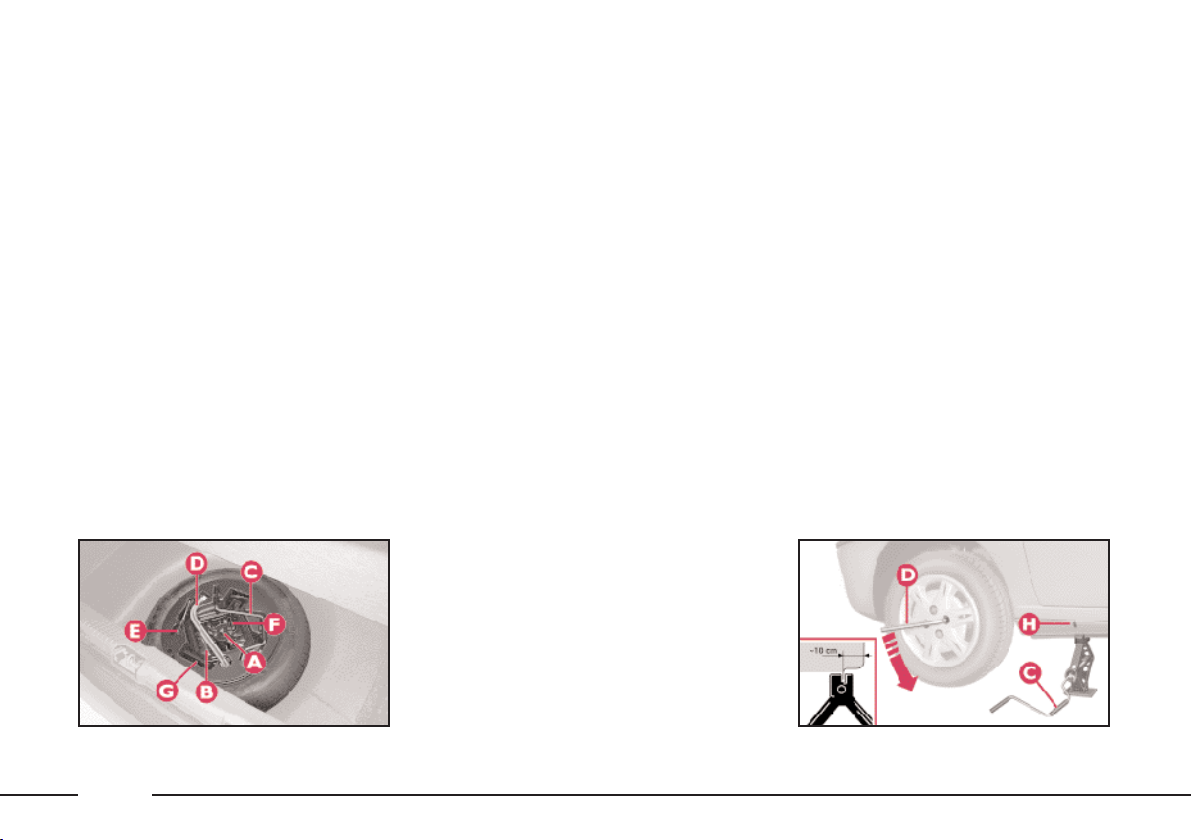
Never fit a standard tyre to a rim
to be used for the space-saver
spare wheel. Have the punctured
tyre repaired and fitted back on as
soon as possible.
No more than one space-saver
spare wheel must be used at the
same time.
Do not grease the bolt threads before fitting them, they could unscrew themselves.
The jack must only be used to
change wheels on the vehicle with
which it is supplied or on vehicles
of the same model. All other uses,
for example raising other vehicles,
must be excluded. Under no circumstances use the jack to carry
out repairs under the vehicle.
If the jack is not used correctly,
the raised vehicle may fall.
Do not use the jack to lift weights
above that indicated on the label
attached to the jack itself.
Never start the engine while the
car is raised by the jack. If travelling with a trailer, detach the
trailer before raising the car.
Snow chains cannot be fitted to
the spare wheel, consequently if a
front tyre is punctured (front drive)
and snow chains need to be fitted,
a standard wheel must be removed
from the back axle and the spacesaver spare wheel fitted in its
place. In this way there will be two
standard wheels on the front and
the snow chains can be fitted.
Incorrect fitting of the wheel hub
could result in the hub coming off
when the vehicle is travelling.
Never tamper with the inflation
valve.
Do not insert any type of tool be-
tween the rim and the tyre.
Periodically check the tyre pressure including that of the sparesaver spare wheel as per the values given in “Technical Specifications”.
fig. 2
96
P4C00400
P4C00401
fig. 3
Page 100
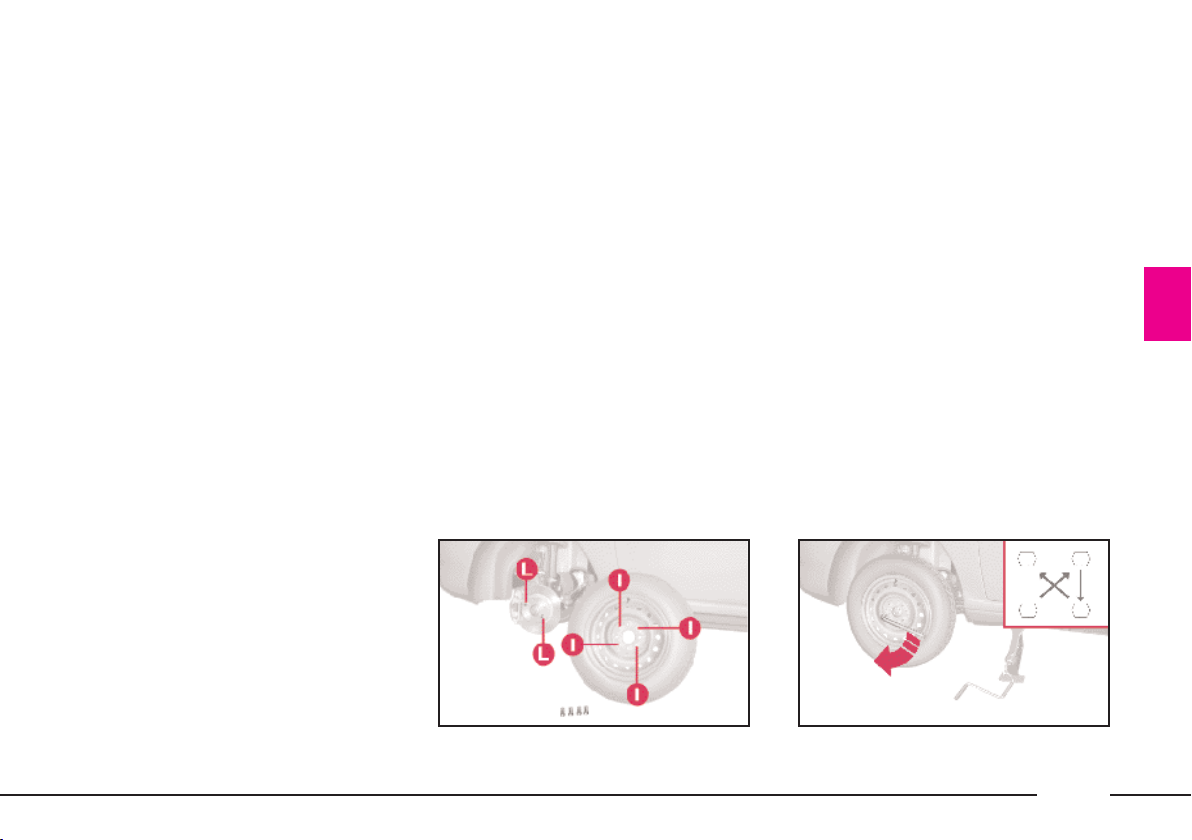
1. STOP THE CAR
– Stop the car so it is not a danger
for on-coming traffic and in such a
position that the tyre can be changed
in safety. The ground must be flat and
adequately firm. During the night,
chose a lit area, if possible.
– Turn engine off and engage the
handbrake.
– Engage first or reverse gear.
– Signal that the car is stopped according to traffic regulations: hazard
lights, warning triangle, etc.
Any passengers must leave the car
and watch out for traffic while the
tyre is being changed.
If the ground is sloping or bumpy,
place wedges or other suitable material for stopping the car under the
wheels.
2. TAKE OUT THE TOOLS,
JACK AND SPARE WHEEL
(space-saver wheel)
They are in the boot.
– Lift the carpeting.
– Unscrew the fastener A (fig. 2)
and take out the tool holder.
The tool holder contains:
B - vehicle tow ring;
C - jack handle;
D - wheel bolt wrench;
E - screwdriver;
F - extension for screwing wheel
bolts and inflation valve cap;
G - jack.
fig. 4
P4C00402
P4C00045
fig. 5
97
 Loading...