

Page 1

Page 2

Dear customer,
Congratulations and thank you for choosing LANCIA.
We wrote this handbook to help you get the most out of your car’s outstanding qualities.
We advise to read it right through before taking to the road for the first time.
You will find information, tips and important warnings regarding the driving of your car to help
you derive the maximum from your LANCIA’s technological features. You will discover unique features and details; you will also find essential information for car care and servicing as well as driving
and operating safety not to mention the long-term wellbeing of your LANCIA.
The enclosed Warranty Booklet lists the services you have acquired and contains details relating to
the following:
• the Warranty Certificate, with terms and conditions for maintaining it
• the range of services offered to LANCIA owners.
We are sure that these instruments will help you easily attune to and appreciate both your new car
and the LANCIA team that will be on hand to provide you with any help you may require.
Best regards and have a great trip!
This Owner Handbook describes all the THESIS versions. You should therefore consider only the
information concerning the engine and bodywork version of the car you have bought.
Page 3

MUST BE READ!
REFUELLING
Petrol engines: only refuel with unleaded petrol with octane rating (RON) no less than 95.
Diesel engines: only refuel with diesel fuel conforming to the European specification EN590.
The use of other products or mixtures may irreparably damage the engine with invalidation of the warranty
due to the damage caused.
ENGINE START-UP
Petrol engines with manual gearbox: make sure the parking brake is pulled (instrument panel warning light x
on); put the gear lever to neutral; press the clutch pedal down to the floor without touching the accelerator, then turn
the ignition key or the Keyless System knob to AVV and release it as soon as the engine starts.
Engines with automatic electronic transmission (COMFORTRONIC): make sure the parking brake is pulled (in-
strument panel warning light x on) and the gear lever is to P; hold the clutch pedal pressed down to the floor
without touching the accelerator, then turn the ignition key or the Keyless System knob to AVV and release it as soon
as the engine starts.
Diesel engines: make sure the parking brake is pulled; put the gear lever to neutral; press the clutch pedal down
to the floor without touching the accelerator, then turn the ignition key or the Keyless System knob to MAR, and
wait for the instrument panel warning light m to go out, then turn immediately the ignition key or the Keyless
System knob to AVV and release it as soon as the engine starts.
PARKING OVER FLAMMABLE MATERIAL
When functioning normally, the catalytic converter reaches high temperatures. For this reason do not park
the car over inflammable material, grass, dry leaves, pine needles, etc.: fire hazard.
K
Page 4

ELECTRICAL ACCESSORIES
If, after buying the car, you decide to add electrical accessories (that will gradually drain the battery), visit a
Lancia Dealership. They can calculate the overall electrical requirement and check that the car's electric system can support the required load.
CODE card
Keep the code card in a safe place, not in the car. You should always keep the electronic code written on the
CODE card with you in case you need to carry out an emergency start-up procedure.
SCHEDULED SERVICING
Correct maintenance of the car is essential for ensuring it stays in tip-top condition and safeguards its safety
features, its environmental friendliness and low running costs for a long time to come.
THE OWNER HANDBOOK CONTAINS …
… information, tips and important warnings regarding the safe, correct driving of your car, and its mainte-
nance. Pay particular attention to the symbols " (personal safety) #(environmental protection) â(the car’s
wellbeing).
PROTECTING THE ENVIRONMENT
A system for continuously monitoring emission system components to ensure greater environmental protection is fitted in your car.
U
Page 5

TRAVELLING SAFELY AND IN HARMONY WITH NATURE
Safety and respect for the environment are the guidelines that inspired the THESIS design from the
drawing board onwards.
This concept has meant that the THESIS has been able to face and pass the strictest safety tests.
So much so that, from this point of view, the car is the best in its class and has probably already incorporated features that belong to the future.
In addition, ongoing research into new and effective features to help safeguard the environment
makes the THESIS a car to imitate for this reason as well.
All versions are in fact equipped with environmental protection devices that reduce harmful exhaust
fumes in compliance with the limits provided for by current legislation.
Page 6

SAFEGUARDING THE ENVIRONMENT
Safeguarding the environment has directed the design and manufacturing of the THESIS right from
the start. The result is the use of materials and the perfection of devices that can reduce or sweepingly reduce harmful influences on the environment.
The THESIS is equipped with environment safeguarding devices which curtail harmful exhaust gas
emissions, is ready to travel well ahead of the most stringent international pollution control standards.
USE OF ENVIRONMENT-FRIENDLY MATERIALS
None of the car’s components contain asbestos. Padding and the climate control system do not contain CFCs (chlorofluorocarbides) - the gases considered responsible for the destruction of the ozone
layer. Other substances that might pollute air and water tables, such as the cadmium in the rust-proof
coating of the bolts, have been completely replaced with substances that do not harm the environment.
Page 7

DEVICES FOR REDUCING PETROL ENGINE EMISSIONS
Three-way catalytic converter (catalytic exhaust pipe)
The exhaust system is equipped with a catalyst made up of noble metal alloys; it is housed in a
stainless steel container capable of withstanding the very high operating temperatures.
The catalyst converts the unburnt hydrocarbons, the carbon monoxide and the nitric oxides found
in the exhaust gases (though in small amounts, thanks to the electronic-injection ignition systems)
into non-polluting substances.
When functioning normally, the catalytic converter reaches high temperatures. For this reason do
not park the car over inflammable material (e.g. paper, fuel oil, grass, dead leaves, etc.).
Lambda sensors
The Lambda sensors detect the oxygen content in the exhaust gas. The signal sent by the oxygen
sensor is used by the injection system electronic control unit to constantly mix air and fuel in the correct proportion.
Fuel evaporation canister
As it is impossible to stop the build up of petrol fumes, also when the engine is not running, the system traps them in a special container holding active carbon.
The fumes are sucked in from here and burnt while the engine is running.
Page 8

DEVICES FOR REDUCING DIESEL ENGINE EMISSIONS
Oxidising catalytic converter
This device converts the polluting substances in the exhaust gas (carbon monoxide, unburnt hydrocarbons and particulates) into harmless substances, thus reducing the smokiness and smell associated with diesel engine exhaust fumes.
The catalytic converter consists of a stainless steel case containing a honeycomb ceramic core in
which there is the precious metal that carries out the catalysing action.
Exhaust Gas Recirculation (E.G.R.) system
This system recirculates or reuses part of the exhaust gas in a proportion which varies according to
engine operating conditions.
When necessary, it is used for the control of nitrogen oxide emissions.
Page 9
THE SIGNS TO HELP YOU DRIVE CORRECTLY
The signs you see on this page are very important. They highlight those parts of the handbook
where, more than elsewhere, you should stop for a minute and read carefully.
As you can see, each sign has a different symbol to make it immediately clear and easy to identify
the subjects in the different areas:
Personal safety.
Important. Total or partial failure to
follow these instructions can place
driver, passengers or others in serious danger.
Environmental protection.
This shows you the correct procedures to follow to ensure that the car
does not harm the environment.
Car wellbeing.
Important. Total or partial failure to
follow these instructions will result
in the risk of serious damage to the
car and may invalidate the warranty
as well.
The texts, illustrations and technical specifications contained in this handbook refer to the car at the time of going to
press.
As part of our ongoing effort to improve our products, LANCIA may introduce technical modifications during production and therefore technical specifications and fittings may be altered without prior notice.
For more detailed information, please apply to LANCIA Dealerships.
Page 10
9
Battery
Corrosive fluid.
SYMBOLS
Special coloured labels have been
attached near or actually on some of
the components of your THESIS.
These labels bear symbols that
remind you of the precautions to be
taken as regards that particular
component.
A list of the symbols to be found on
your THESIS is given below with the
name of the component to which it
relates at the side of it.
These symbols are divided into the
following four categories: danger,
prohibition, warning and obligation.
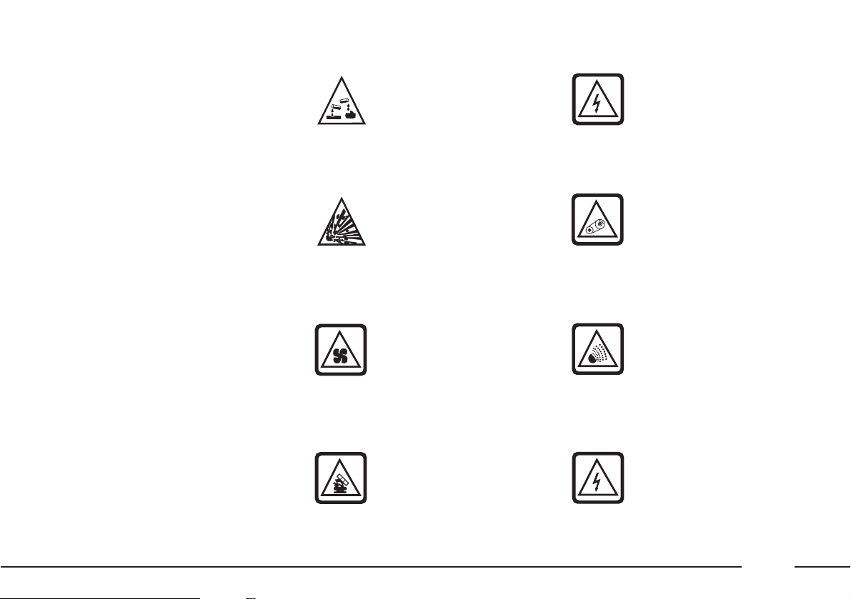
DANGER SYMBOLS
Battery
Explosion.
Fan
May cut in automatically
even when the engine is
turned off.
Expansion tank
Do not remove the cap
when the coolant is hot.
Coil
High voltage.
Belts and pulleys
Moving parts; keep parts
of the body and clothes
away.
Climate control tubing
Do not open. Gas under
high-pressure.
Front headlights
Danger - Electric shocks.
Page 11
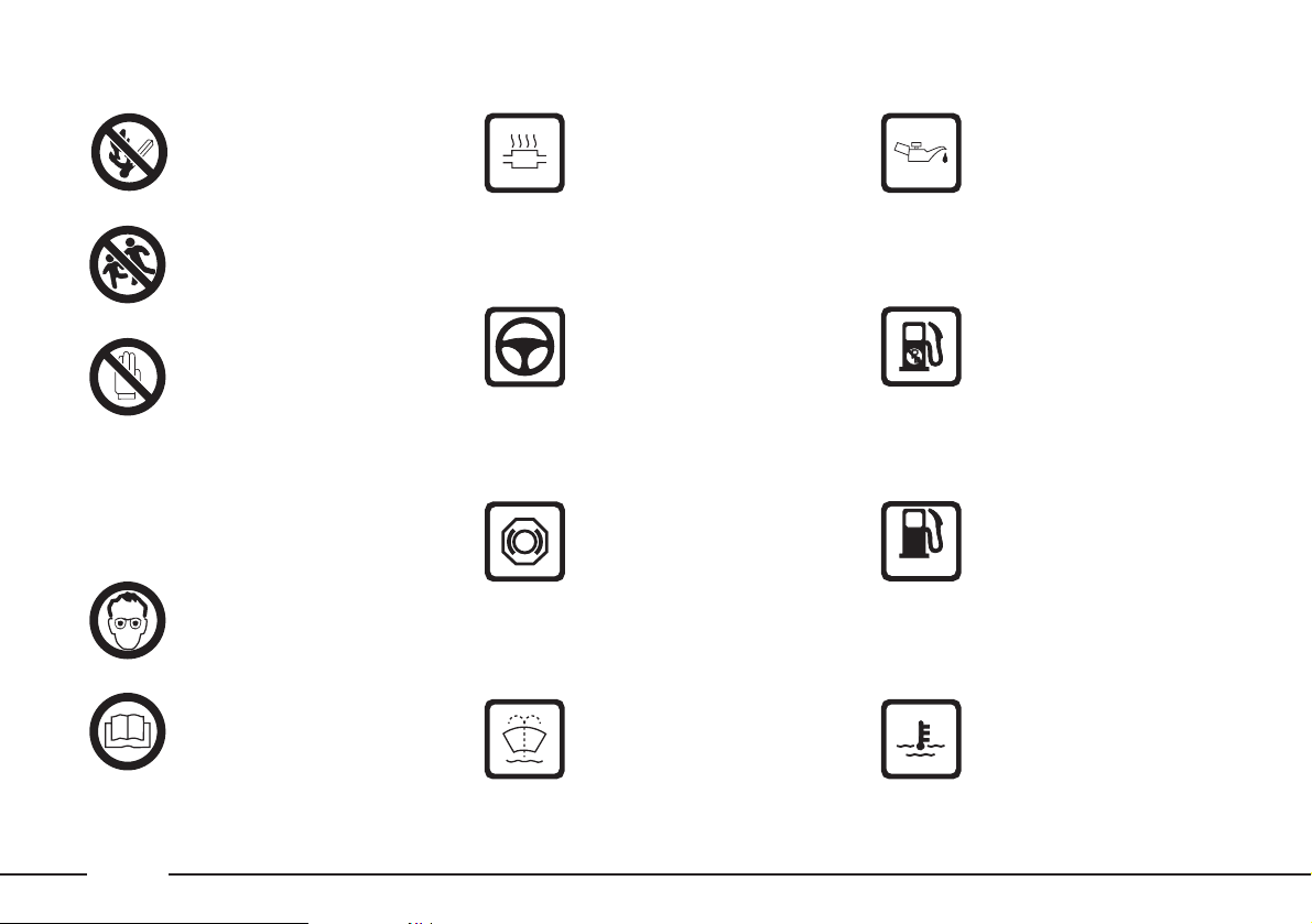
Diesel engines
Use diesel fuel only.
Expansion tank
Only use fluid of the type
specified in section
“Capacities”.
Battery
Protect your eyes.
Battery
Jack
See the Owner hand-
book.
OBLIGATION SYMBOLS
10
Battery
Keep away from naked
flames.
Battery
Keep away from chil-
dren.
Heat shields - belts pulleys - fan
Do not touch.
PROHIBITION SYMBOLS
Power steering
Do not exceed the maximum fluid level in the
reservoir. Use only the
fluid specified in section
“Capacities”.
Catalytic converter
Do not park over inflammable materials. See
chapter: “Protecting the
emission control devices”.
WARNING SYMBOLS
Engine
Use only the oil specified
in section “Capacities”.
Unleaded petrol vehicle
Use only unleaded petrol
with a rated octane number (R.O.N.) of not less
than 95.
Windscreen wiper
Only use fluid of the type
specified in section
“Capacities”.
Brake circuit
Do not exceed the maximum fluid level in the
reservoir. Use only the
fluid specified in section
“Capacities”.
DIESEL
Page 12

GETTING TO KNOW YOUR CAR
DRIVING YOUR CAR
IN AN EMERGENCY
CAR MAINTENANCE
TECHNICAL SPECIFICATIONS
INDEX
CONTENTS
11
Page 13
12
fig. 1
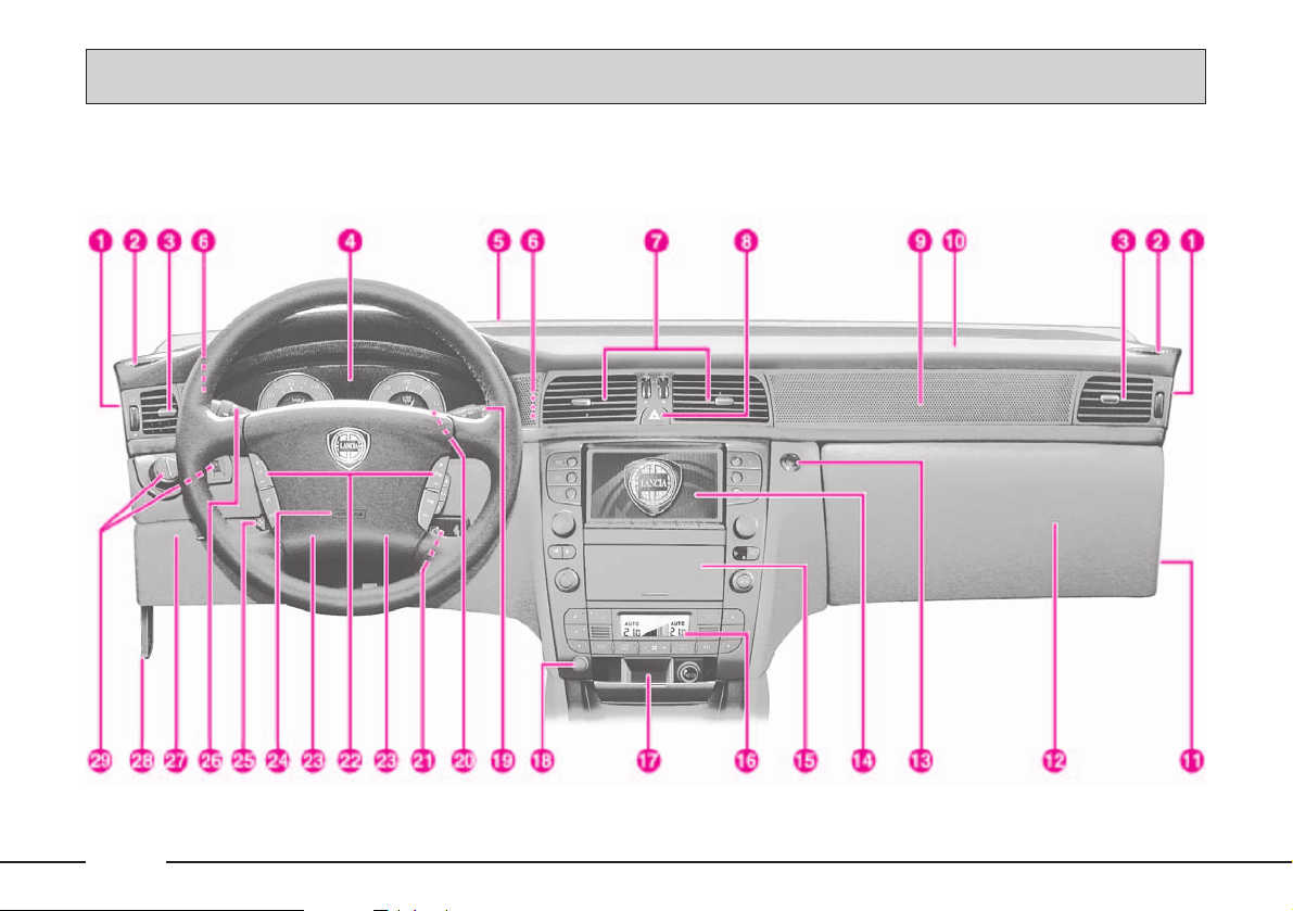
DASHBOARD
The presence and the position of the instruments and warning lights may vary according to the version.
L0A0001b
GETTING TO KNOW YOUR CAR
Page 14

13
1) Front door air outlets
2) Side window vents
3) Side vents
4) Instrument panel
5) Windscreen vent
6) Driver’s side vents
7) Central vents
8) Hazard light switch
9) Passenger’s side vent
10) Front passenger’s airbag
11) Front passenger’s airbag deactivation switch
12) Glove compartment/CD CHANGER compartment/
power socket
13) Glove compartment on/off button
14) CONNECT multifunction display (for control
description see the following pages)
15) Cassette player, CD and SIM telephone card slot flap
16) Automatic climate control and heated rear window
switch
17) Ashtray and cigar lighter
18) SOS button (for assistance services and functions)
19) Windscreen/headlight wiper/washer stalk
20) Trip meter reset button (long pressure)/Button for
deleting failure messages on the display (short pressure)
21) Ignition switch
22) CONNECT controls on the steering wheel (for con-
trol description see the following pages)
23) Horn
24) Driver’s airbag
25) Steering wheel electric adjustment button
26) Radar Cruise Control controls/Cruise Control/direc-
tion indicator stalk and main/dipped beam headlight switch
27) Glove compartment/fusebox cover
28) Bonnet opening lever
29) Outside light stalk knob - Front and rear fog light
buttons - Instrument panel dimmer and twilight sensor sensitivity ring nuts
Page 15
14
fig. 2
CONNECT INFOTELEMATIC SYSTEM
The key for this figure is
on pages 16-17.
L0A5001b
Page 16
15
THESIS CONNECT infotelematic
system, in its most refined version,
includes: colour TV set, sound system with cassette player, CDROM/Audio CD player, CD-changer, GSM cell phone, navigator, trip
computer and voice commands (for
certain functions of cell phone,
audio system and navigator).
The following pages describe the
system controls and main functions.
The car is provided with a special
supplement dealing with CONNECT
infotelematic system to be used as
quick reference guide for using the
system. Read through this supplement carefully and keep it always
within reach (e.g. in the glove compartment).
IMPORTANT For the navigation
system of the CONNECT, only use
only the original CD provided with
the car or, in any case other CDs of
the same brand.
If you drive with the volume too high you put both
your own life and that of
others in jeopardy. You should
adjust the volume so that you can
hear noises from outside the car
(e.g. horns, ambulance/police
sirens, etc.).
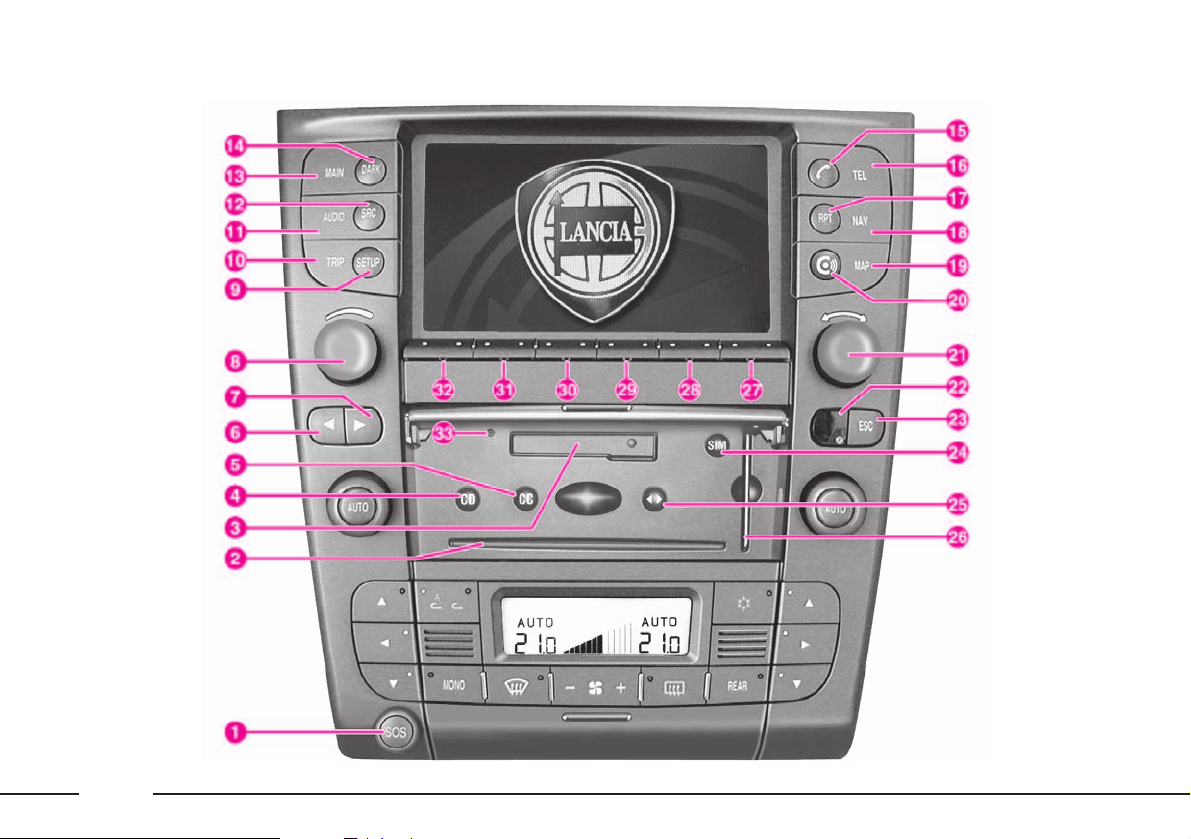
CONNECT CONTROLS (fig. 2)
The CONNECT system functions
can be managed by means of 29
buttons and 2 rotating selectors
(knobs). Certain controls have multiple functions that are dependent on
the system operating conditions
active.
The type of function that can be
actuated by means of the controls
depend, in some cases, on how long
the button is pressed down (long or
short push), as shown in the following table.
The Lancia navigation
system helps driver while
he drives, by suggesting
vocally or graphically, the optimum routing to reach his preset
destination. Navigation system
suggestions do not excuse driver
from his full responsibilities due
to his driving behaviour and to
his compliance with road and
other traffic regulations. The
responsibility for road safety
always lies with the car driver,
and it falls on him in any case.
IMPORTANT The provided phone
is of the Single-Band type and therefore if your network provider is not
operating with the 900 Mhz GSM
standard, coverage troubles may arise
notwithstanding the roaming. Contact
your network provider for further information.
Page 17

16
Legend
1 – SOS
2
3
4 – CD
5 – CC
6 – ¯
7 – ˙
8
9 – SETUP
10 – TRIP
11 – AUDIO
12 – SRC
13 – MAIN
Short push
(less than 2 seconds)
Assistance services and functions
Slot for navigator CD-ROM or Audio CD
Slot for cassette
Eject navigator CD-ROM or Audio CD
Eject cassette
Radio mode: search for the first radio station that can be
tuned at a lower frequency
CD mode: selection of the previous track
Cassette mode: fast tape rewind with return to beginning
of listened track or to previous track
TV mode: search for the first channel that can be tuned
at a lower frequency
Radio mode: search for the first radio station that can be
tuned at a higher frequency
CD mode: selection of the next track
Cassette mode: fast tape feed to end of listened track or
to next track.
TV mode: search for the first channel that can be tuned
at a higher frequency
System switching on/off: pressing the knob
Volume control: rotating the knob
System set-up and car functions that can be
modified
Trip computer screen selection
Turning on Audio mode and/or selecting specific screen
display
Audio source selection: FM1, FM2, FM3-AS, MW, LW,
CC, CD, CDC, TV
MAIN screen selection (main screen)
Long push
(more than 2 seconds)
–
–
–
–
–
Radio mode: actuation of the “Scan” mode with
scanning of the stations in the selected
radio band starting from the lower frequency ones
CD mode: fast backward
Cassette mode: fast tape rewinding
Radio mode: actuation of the “Scan” function with
station scanning in the radio band
selected starting from the higher frequency ones
CD mode: fast forward
Cassette mode: fast tape feed
–
–
–
Turning off Audio mode
(Radio, CC, CD/CDC)
–
–
Page 18

17
Legend
14 – DARK
15 –
£
16 – TEL
17 – RPT
18 – NAV
19 – MAP
20 – •
21
22
23 – ESC
24 – SIM
25 – ¯˙
26
27-28-29-
30-31-32
33
Short push
(less than 2 seconds)
DARK mode actuation: the display is completely darkened
Forwarding the phone call set
Accepting the incoming call
Ending the ongoing call
Phone mode actuation and/or specific screen selection
Repetition of the last navigator voice instruction
Navigation mode actuation and/or specific screen
Navigator map mode selection
Access to Targasys services
Required function selection by
turning the knob.
Selected function confirmation by
pressing the knob.
Remote control receiver
Exit from a selection option or shift from a submenu to a
higher menu
Eject SIM telephone card
Reverse tape side being listened to
Slot for SIM telephone card
Double “multifunction” buttons: their functions
depend on the system active mode shown on the display.
The function associated to the “multifunction” buttons is
identified from time to time by a writing on the display,
just next to each button
In some cases, the writing covers several adjacent buttons:
the function associated to all these buttons is the same.
Radio/TV mode: select stored stations.
CD-changer mode: select CD in the magazine.
Reset button for system restart
Long push
(more than 2 seconds)
–
Refusing the incoming phone call
Phone mode off
–
–
–
–
–
–
–
–
–
–
Radio/TV mode: station storage
–
Page 19
18
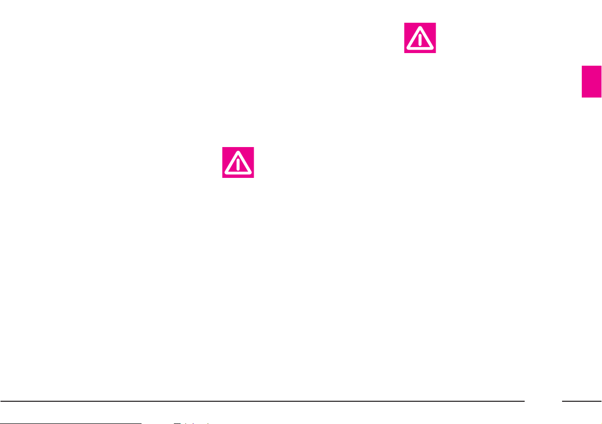
CONTROLS ON THE STEERING
WHEEL (fig. 3)
The main CONNECT function
controls are duplicated on the steering wheel, thus facilitating its control.
The steering wheel also includes
the VOICE button, used to switch
the phone/audio system voice controls on/off, and record short voice
messages.
The control functions are as follows:
A - Voice Recognition:
– voice recognition on/off:
short push
– voice message memorization:
long push
– voice recorder stop: short
push
B - Audio source selection: FM1,
FM2, FM3-AS, MW, LW, CC, CD,
CDC, TV
C - Turning down the volume
D -Turning up the volume
E - Radio mode: search for the first
radio station that can be tuned
at a higher frequency
Cassette mode: fast tape feed to
end of listened track or to next
track
CD/CDC mode: selection of
next track
TV mode: channel search in an
increasing order
F - Radio mode: search for the first
radio station that can be tuned
at a lower frequency
Cassette mode: fast tape rewind
with return to beginning of listened track or to previous track
CD/CDC mode: selection of
previous track
TV mode: search for the first
channel that can be tuned at a
lower frequency
G - Cyclic selection of main screens
MAIN – AUDIO – TRIP – SETUP –
TEL – NAV – CONNECT (access to
Targasys services)
H - Phone button:
– accepting the incoming call:
short push
– ending the ongoing call: short
push
– to display the last dialled
number: brief press
– forwarding the call set: short
push
– reading the SMS just
received: short push
– refusing the incoming call:
long push
L - Display function upward selec-
tion
M - Selected function confirmation
N - Display function downward
selection
fig. 3
L0A5002b
Page 20
19
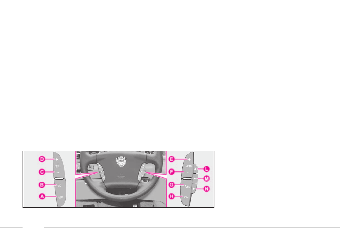
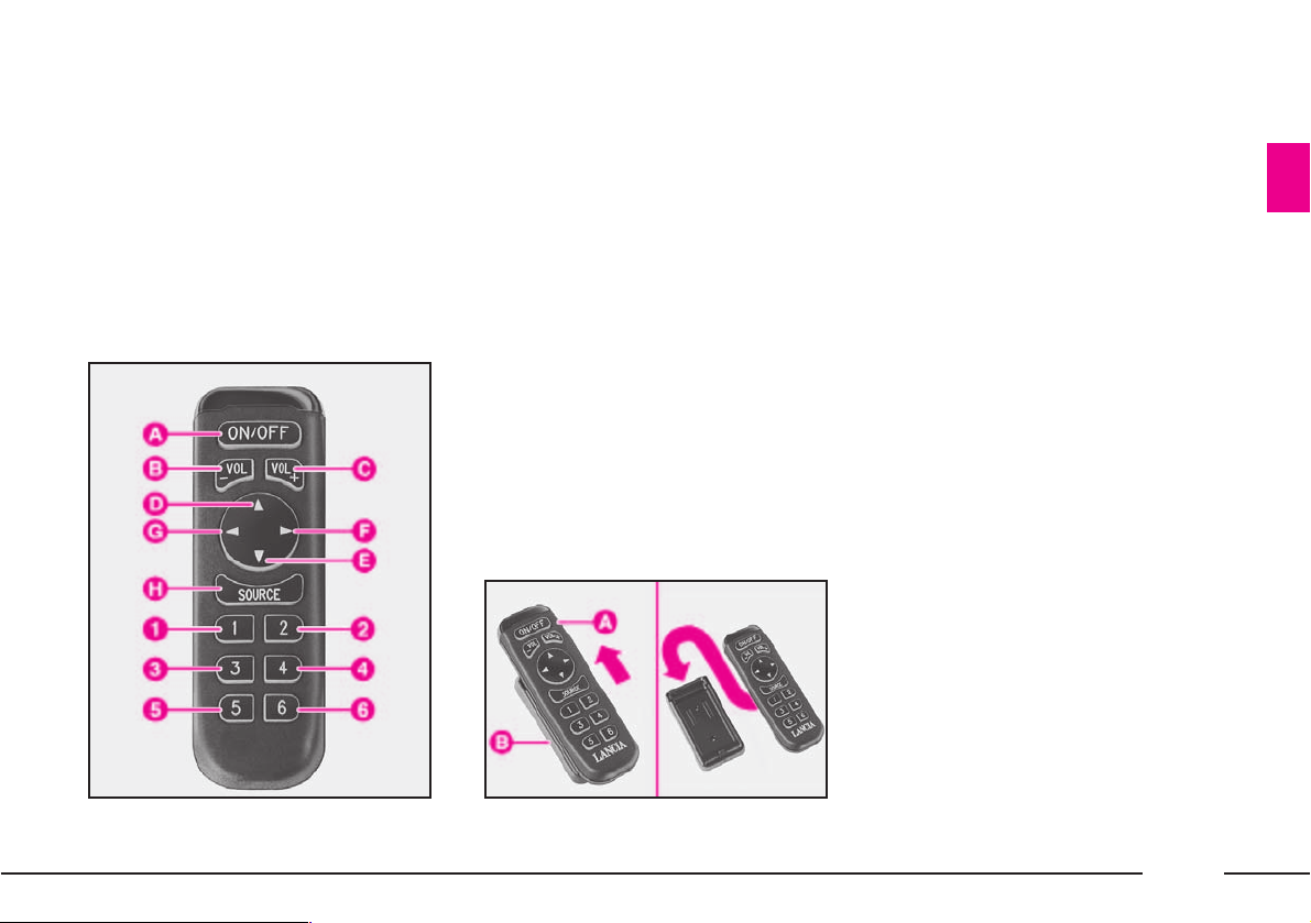
REMOTE CONTROL (fig. 4-5)
The infrared-ray remote control
controls certain main functions of
the TV and audio system.
The remote control can be used
only when the CONNECT is
switched on.
The remote control functions can
be switched off and on again by
selecting the corresponding item of
the SETUP function (set-up).
To use remote control A (fig. 5) take
it out from support B.
The remote control buttons perform the following functions (fig. 4):
A - Radio mode: “Audio Mute”
function on/off (volume muting) only with TP function
active (symbol “√” near TP on
the main Radio screen).
CC/CD/CDC mode: play/stop
current track.
TV mode: TV off and return to
previously active Audio source
screen
B - Turning down the volume
C - Turning up the volume
D - Radio mode:
– short push = search for the
first radio station that can be
tuned at a higher frequency
– long push = actuation of the
“Scan” function with scanning of the stations in the
selected radio band starting
from the higher frequency
ones
CD mode:
– short push = selection of next
track
– long push = fast forward
Cassette mode:
– short push = fast tape feed to
end of listened track or to
next track
– long push = fast tape feed
TV mode: search for the first
channel that can be tuned at a
higher frequency
fig. 5
L0A5003b
fig. 4
L0A5004b
Page 21

20
E - Radio mode:
– short push = search for the
first radio station that can be
tuned at a lower frequency
– long push = actuation of the
“Scan” function with scanning of the stations in the
selected radio band starting
from the lower frequency
ones
CD mode:
– short push = selection of pre-
vious track
– long push = fast backward
Cassette mode:
– short push = fast tape rewind
with return to beginning of
listened track or to previous
track
– long push = fast tape rewind
TV mode: search for the first
channel that can be tuned at a
lower frequency
F - Radio mode:
– short push = search for the
first radio station that can be
tuned at a higher frequency
– long push = actuation of the
“Scan” function with scanning of
the stations in the selected radio
band starting from the higher
frequency ones
CD mode:
– short push = selection of next
track
– long push = fast forward
Cassette mode:
– short push = fast tape feed to
next track
– long push = fast tape feed
TV mode: search for the first
channel that can be tuned at a
higher frequency
G - Radio mode:
– short push = search for the
first radio station that can be
tuned at a lower frequency
– long push = actuation of the
“Scan” function with scanning of the stations in the
selected radio band starting
from the lower frequency
ones
CD mode:
– short push = selection of pre-
vious track
– long push = fast backward
Cassette mode:
– short push = fast tape rewind
to previous track
– long push = fast tape rewind
TV mode: search for the first
channel that can be tuned at a
lower frequency
H -Audio source selection: FM1,
FM2, FM3-AS, MW, LW, CC,
CD, CDC, TV
1-2-3-4-5-6 - Radio mode:
– short push = Recall of stored
stations no. 1-2-3-4-5-6
– long push = storing the sta-
tion being listened to
CD-changer mode: CD selection from 1 to 6
TV mode: stored channel selection from 1 to 6
Page 22

21
Function
Audio module switching on
Audio module switching off
Audio mute (only with TP
active on the main
Radio screen)
Audio source selection
Turning the volume
up/down
Selection of stored
radio stations
Radio station memorization
Search for the first radio
station that can be tuned
at a higher frequency
Search for the first radio
station that can be tuned
at a lower frequency
CONNECT buttons
Short push on AUDIO button
Long push on AUDIO button
“Audio Mute” selection and con-
firmation on Radio menu by the
right knob 21 (fig. 2)
Press the multifunction buttons FM, AM, CC, CD, CDC,
TV or the SOURCE button
Rotate the left-hand knob
Short push on buttons
1 to 6
Long push on buttons 1 to 6
Short push on button ˙
Short push on button ¯
Steering wheel buttons
–
–
–
Press the SOURCE button
Press VOL+/- buttons
–
–
Short push on SCAN+ button
Short push on SCAN- button
Remote control buttons
–
–
Press the ON/OFF key
Press the SOURCE button
Press VOL+ or VOL- buttons
Short push on buttons
1 to 6
Long push on buttons 1 to 6
Short push on button N
Short push on button O
AUDIO AND TV FUNCTION: CONTROL SUMMARIZING TABLE
The TV and audio system (FM/AM radio and Cassette/CD/CDC player) functions can be switched on/off without distinction by means of the controls on the CONNECT, the steering wheel or the remote control. To make it easier getting
acquainted with the controls, a table is shown below with the various functions and their respective control buttons.
To use voice commands, refer to the relevant chapter provided in the CONNECT supplement.
Page 23

22
Function
Actuation of the
“Scan” function with scanning
of the stations in the selected
radio band starting from the
higher frequency ones
Actuation of the
“Scan” function with scanning
of the stations in the selected
radio band starting from the
lower frequency ones
Reversing
cassette tape
Fast tape rewind
to previous track
Fast tape
rewinding
Fast
tape feed
to next track
Fast tape feed
Play/pause of listened
track CC/CD
Search for next
track while
playing a CD
CONNECT buttons
Long push on button ˙
Long push on button ¯
Press button ¯˙
Short push on button ¯
Long push on button ¯
Short push on button ˙
Long push on button ˙
Push multifunction buttons
Play/Pause
Short push on button ˙
Steering wheel buttons
Long push on SCAN+ button
Long push on SCAN- button
–
Short push on SCAN- button
Long push on SCAN- button
Short push on SCAN+ button
Long push on SCAN+ button
–
Short push on SCAN+ button
Remote control buttons
Long push on button N
Long push on button
O
–
Short push on button
O or
¯
Long push on button O
Short push on button N or ˙
Long push on button N
Push ON/OFF button
Short push on button ˙
Page 24

23
Function
Search for previous track
while playing a CD
Selection of CD in CDC
mode
Play/stop
the track being listened to
in CDC mode
Selection of memorized TV
channels
Search for next tunable
TV channel
Search for previous tunable
TV channel
TV module off (return to
previously active
Audio source screen)
CONNECT buttons
Short pressure of button ¯
Press buttons 1 to 6
–
Press buttons 1 to 6
Short push on button ˙
Short push on button ¯
Press OFF multifunction key
Steering wheel buttons
Short push on SCAN- button
–
–
–
Press SCAN+ button
Press SCAN- button
–
Remote control buttons
Short pressure of button ¯
Press buttons 1 to 6
Press ON/OFF button
Press buttons 1 to 6
Short push on button N
Short push on button
O
Press the ON/OFF key
Page 25
It is absolutely forbidden
to carry out whatever after-market operation in-
volving steering system or steering
column modifications (e.g.: installation of anti-theft Device) that
could badly affect performance
and safety, cause the lapse of warranty and also result in non-compliance of the car with homologation requirements.
24
STEERING COLUMN LOCK
The steering column lock is
engaged automatically after removing the ignition key.
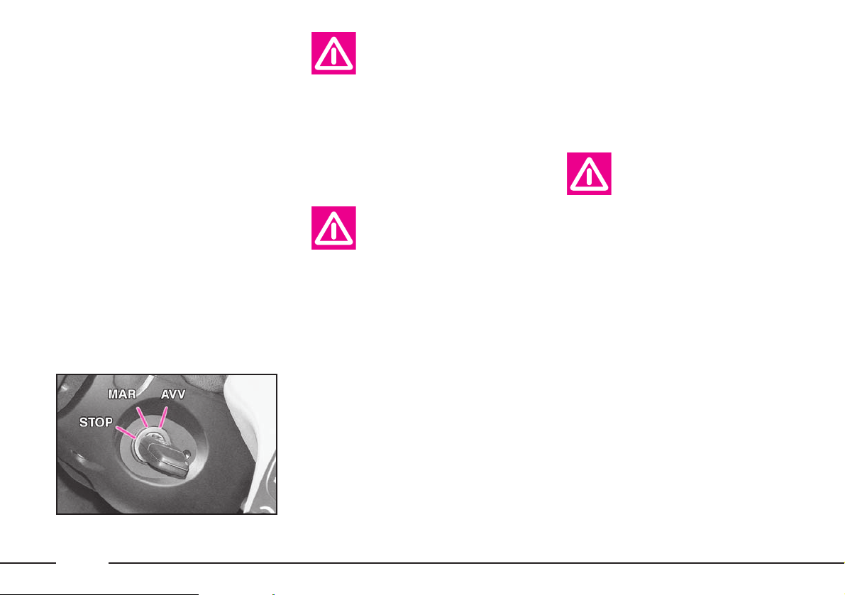
IGNITION
SWITCH
The key can be turned to three dif-
ferent positions (fig. 6):
STOP: engine off, key can be
removed, steering column locked.
Some electrical devices can be operated (e.g. CONNECT).
MAR: driving position correspond-
ing to: dashboard on and steering
column lock off. All the electrical
devices can be operated.
AVV: engine ignition. Release the
key as soon as the engine is started.
If the ignition switch has
been tampered with (e.g.
someone has tried to steal
your car), get a Lancia
Dealership to make sure it is still
functioning properly before you
start driving again.
Always remove the ignition key when you get out
of the car. This will pre-
vent anyone from accidentally
working the controls. Remember
to apply the handbrake and, if
the car is faced down on a steep
slope engage the first gear. If it is
facing up, engage the reverse
gear.
IMPORTANT For versions equip-
ped with the recognition system,
refer to paragraph “Recognition system (Keyless System)” in this chapter.
fig. 6
L0A0021b
Versions with Keyless System
The steering column lock is
engaged when central door locking
is actuated by means of the remote
control. This condition is indicated
on the instrument panel display by
message “STEERING LOCKED
WHEN DOORS CLOSED”.
Page 26
25
Steering column lock always off
The user can set the condition
“Steering column lock always off”
by means of the CONNECT menu.
To set this mode, refer to the CONNECT supplement provided with
the car.
In an emergency
The steering column lock cannot be
disengaged when the battery is run
down. In this case, open the bonnet
with the emergency key and connect
an auxiliary battery to the car battery.
Do not carry out this
procedure if you lack
experience; if it is not
done correctly it can cause very
intense electrical discharges and
the battery might even explode.
Contact a Lancia Dealership. In
any case, refer to paragraph
“Jump starting”.
The steering column
lock is not engaged if central door locking is actu-
ated by means of the emergency
key or if central locking is activated automatically (“Autoclose”
function).
The steering column lock is disengaged automatically when depressing the clutch pedal (versions with
manual gearbox) or brake pedal
(versions with automatic transmission).
Before opening the luggage compartment bonnet
to reload the battery or to
connect an auxiliary battery, carefully read and comply with the instructions contained in the paragraph “If battery is to be disconnected” in the chapter “In an
emergency”.
Page 27

26
THE LANCIA CODE
SYSTEM
To further protect your car from
theft, it has been fitted with an
engine immobilising system (Lancia
CODE) which is automatically activated when the ignition key is
removed. An electronic device, in
fact, is fitted in each ignition key
grip. The device transmits a radiofrequency signal when the engine is
started through a special aerial built
into the ignition switch. The modulated signal is a password. Only if
the control unit recognises the key
can the engine be started.
OPERATION
Each time the ignition key is
turned to STOP the Lancia CODE
system will deactivate the engine
electronic control unit functions.
When the key is turned to MAR to
start the engine, the Lancia CODE
system sends a password code to the
engine control unit to deactivate the
function lock. The encoded and
variable code, randomly selected
from over four billion possible combinations, is only sent if, in turn, the
system has recognised the code
transmitted by the electronic device
built into the ignition key via an aerial surrounding the ignition switch.
If the code has not been recognised
correctly, the symbol Y will appear
on the instrument panel display,
together with the message “VEHICLE PROTECTION SYSTEM
FAULT”.
In this case, turn the key to STOP
and then back to MAR. If the engine
remains immobilised, try with the
other keys provided with the car. If
you are still unable to start the
engine, carry out the emergency procedure described in chapter “In an
emergency”, and contact your
Lancia Dealership.
IMPORTANT Each key has its
own code that must be stored in the
system control unit. For storing new
keys, up to a maximum of eight,
apply solely to Lancia Dealership
taking with you all the keys in your
possession, the CODE card, a personal identity document and the
documents that certify car possession.
Page 28
27
The codes of any keys
that are not available
when the new storage pro-
cedure is carried out will be
deleted from the memory to prevent any lost or stolen keys being
used to start the engine.
IMPORTANT If symbol Y lights
up when the car is running:
1) If the symbol lights up together
with the message “VEHICLE PROTECTION SYSTEM FAULT”, this
means that the system is running a
self-test (e.g. due to a voltage drop).
The first time you stop, you can test
the system as follows: switch the engine off by turning the ignition key to
STOP then turn the key back to
MAR: the symbol will light up and go
out in about 1 second. If the symbol
remains on, repeat the above procedure, leaving the key at STOP for
longer than 30 seconds. If the problem persists, contact your Lancia
Dealership.
2) If the symbol stays on, this
means that the code has not been
recognised. In this case, turn the key
to STOP and then back to MAR. If
the engine remains immobilised, try
with the other keys provided with
the car. If you are still unable to
start the engine, carry out the emergency procedure (see chapter “In an
emergency”), and contact your
Lancia Dealership.
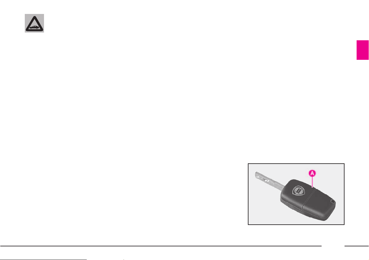
THE KEY
The car is delivered with two
copies of the key A (fig. 7) with
metal insert and power-assisted
opening with built-in remote control
for remote door opening/closing,
boot/tailgate opening and switching
the electronic alarm on/off.
fig. 7
L0A0022b
Page 29
28
The key operates:
– ignition switch;
– steering column lock disengage-
ment;
– front door lock latches;
– dead lock device;
– remote door opening/closing;
– remote bonnet lock locking/
unlocking;
– remote boot lock locking/unlock-
ing;
– remote bonnet opening;
– electronic alarm system;
– passenger side airbag deactiva-
tion;
– rear airbag deactivation;
– window and sunroof opening/
closing.
The electronic components inside the key may
be damaged if the key is
exposed to direct sunlight.
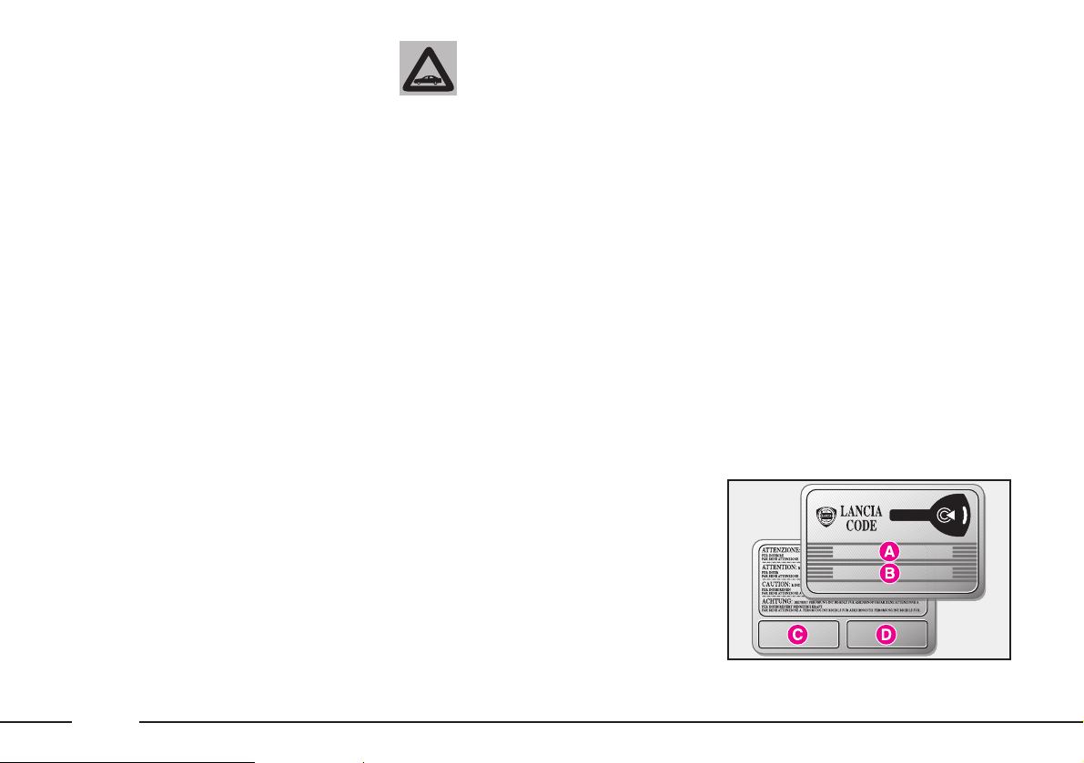
Code card
The CODE card (fig. 8) is also sup-
plied with the keys and bears the
following:
A - The electronic code, to be used
for emergency starting.
B - The mechanical key code to be
given to the Lancia Dealership
when ordering duplicate keys.
C and D - The spaces for the elec-
tronic alarm remote control stickers.
By the CONNECT menu, the system can be set in such a way that
when the door opening button is
pressed, only the driver’s door or all
the doors are unlocked. To get
acquainted with the operation logic
of the key with remote control and
all the settings that can be modified,
refer to the following paragraph
“Electronic alarm”.
IMPORTANT If the relevant function has been actuated by the CONNECT menu, the boot lock will
automatically be released when central door opening is actuated.
fig. 8
L0A0023b
Page 30
29
The code numbers written on the
CODE card must be kept in a safe
place (not in the car).
You should always have the electronic code number written on the
CODE card with you at all times in
case you need to perform an emergency start-up.
All the keys and the
CODE card must be
handed over to the new
owner when selling the car.
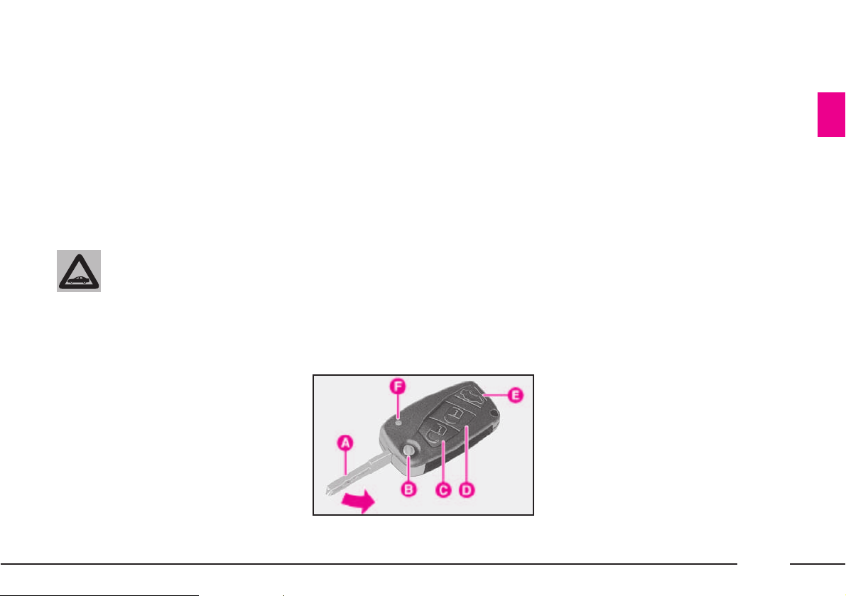
The key (fig. 9) has:
– metal insert A that can be
enclosed in the key grip;
– button B to open the metal insert;
– button C for remote door unlock-
ing and electronic alarm deactivation at the same time;
– button D for remote door and
boot locking and electronic alarm
activation at the same time;
– button E for remote bonnet open-
ing;
– led F (where required) indicating
code sending to the electronic alarm
system receiver.
Prolonged pressure (more than 2
seconds) of button C will actuate the
opening of all the door windows and
the sunroof, to aerate the passenger
compartment: opening is interrupted when the button is released.
Similarly, door windows and sunroof can be closed when closing the
doors by pressing down (for more
than 2 seconds) the remote locking
button D until they are completely
closed.
Door windows and sunroof closing
is interrupted when button D is
released.
Pressing again the button D within
1 second will activate the dead lock
device (see paragraph “Doors”).
fig. 9
L0A0024b
Page 31

30
After activating the dead
lock device it will be
impossible to get out of
the passenger compartment: for
this reason this device must be
activated only after making sure
that the passenger compartment
is empty.
The metal insert A (fig. 10) of the
key operates:
– ignition switch;
– steering column lock disengage-
ment;
– the front door locks;
– the boot lock;
– the passenger side airbag deacti-
vation switch;
– the rear airbag deactivation
switch.
To make the metal insert come out
of the key handle, press button B.
Take the greatest care
when pressing button B
(fig. 10), to avoid that the
metal insert A can cause injury or
damage when coming out. Button
B must be pressed only when the
key is far from your body, in particular your eyes, and from
objects subject to deterioration
(e.g. clothes). Do not leave the key
unattended to prevent anyone,
especially children, from handling it and pressing button B
unintentionally.
To put the metal insert into the key
grip, keep button B depressed and
rotate the insert in the direction
shown by the arrow until hearing the
locking click. Then release button B.
fig. 10
L0A0025b
Page 32

31
Remote control
The remote control is built into the
key and has three buttons C, D and E
(fig. 9) and a led F (where required).
The buttons respectively operate the
central opening control, the central
locking control and the boot lock;
the led flashes while the transmitter
is sending the code to the receiver.
This code (rolling code) changes at
each transmission.
To actuate the remote central door
opening, press button C (fig. 9): the
doors will unlock and the indicators
will flash twice. To actuate central
door locking, press button D: the
doors will lock and the indicators
will flash once.
By pressing button C, also the
alarm system will be switched off; by
pressing button D, the alarm system
will be switched on and the key led
F (where required) will flash while
the transmitter sends the code to the
receiver: this code (rolling code)
varies at each transmission.
IMPORTANT When the remote
control battery is run down, the
dashboard display will show the
symbol Y accompanied by the message “DISCHARGED REMOTE
CONTROL BATTERY”. In this
case, it is advisable to replace the
battery as soon as possible, by following the instructions given below.
IMPORTANT The remote control
operation depends on different factors, such as possible interference
with electromagnetic waves emitted
by external sources, the battery
charge and the presence of metal
objects near the key and the car. It is
however possible to perform any
procedure using the metal insert of
the key.
Page 33

32
REMOTE CONTROL FUNCTIONS
The remote control allows to control the functions that can be modified directly by the user, through the CONNECT set-
ting menu, or by the Lancia Dealership. The following table lists the system options and the settings provided when the
car is delivered to the customer.
Requested function
Central door opening
(double short blink
of direction indicators)
Action performed on the
remote control
Single short pressure
of button C (fig. 9)
Subsequent double short
pressure (within 1 second)
of button C
Prolonged pressure of
button
C (more than 2
seconds)
Standard settings
– Electronic alarm switching
off
– Door and tailgate unlocking
– Door deadlock device
switching off (if on)
– Ceiling light switching in
for about 30 seconds or until
the key is turned to MAR
– Door unlocking
– Opening of the windows
and sunroof (to complete
opening or until the button
is released)
Functions that can be
modified
– Driver’s door unlocking
– Tailgate always locked
Page 34

33
Requested function
Central door locking
(single prolonged blink
of direction indicators)
Tailgate unlocking
and tailgate
lifting (double blink of
direction indicators)
Action performed on the
remote control
Single short pressure
of button D (fig. 9)
Subsequent double short
pressure (within 1 second)
of button D
Prolonged pressure of button
D (more than 2 seconds)
Single short pressure of
button
E (fig. 9)
Prolonged pressure of button
E (more than 1 second)
Standard settings
– Electronic alarm
switching on
– Door and boot locking
– Ceiling lights switching off
– Door deadlock device
switching on
– Closing of windows and
sunroof (to complete closing
or until the button is released)
– Ceiling lights switching off
– Boot alarm
switching off
– Tailgate lock
unlocking
– Boot alarm switching off
– Tailgate unlocking and
tailgate raising
Functions that can be
modified
Page 35

34
Requested function
Central door opening
Central door locking
Action performed with the
metal insert of the key
Single, clockwise rotation of
the key in the lock latch of
one of the doors
Single, anticlockwise rotation
of the key in the lock latch
of one of the doors
Standard settings
– Door and tailgate unlocking
– Door deadlock device
switching off (if on)
– Ceiling lights switching on
for about 30 seconds, or until
the key is turned to MAR
– Doors and tailgate locking
– Ceiling lights switching off
Functions that can be
modified
– Driver’s door unlocking
– Tailgate always locked
FUNCTIONS THAT CAN BE ACTUATED WITH THE METAL INSERT OF THE KEY
The metal insert of the key allows to control the functions that can be modified directly by the user, by means of the
CONNECT setting menu, or by the Lancia Dealership. The following table lists the system options and the settings provided when the car is delivered to the customer.
Page 36

35
ACTUATION LOGIC OF THE BOOT LOCK BY MEANS OF THE REMOTE CONTROL
Central door locking system
condition
Operation to open
the boot
Operation to close
the boot
Bound to central
door locking
Off
Press the boot button
The lock remains
unlocked when closing the boot
On
Press the remote
control button
E (fig. 9)
then press the boot
button or keep the
remote control button
depressed
(more than 1 second)
The lock remains
unlocked when
closing the boot.
For locking the lock,
press the remote
control button D
(fig. 9)
Not bound to the central
door locking
Off
Press the remote
control button
E (fig. 9),
then press the boot
button or keep the
remote control button
depressed
(more than 1 second)
The lock remains
unlocked when the
boot is closed.
The lock is automatically locked when the
car speed exceeds 20
km/h approximately
On
Press the remote
control button
E (fig. 9),
then press the boot
button or keep
the remote control
button depressed
(more than 1 second)
The lock remains
unlocked when closing
the boot.
For locking the lock,
press the remote
control button
D (fig. 9
Page 37

36
ACTUATION LOGIC OF THE BOOT LOCK BY MEANS OF THE METAL INSERT
OF THE KEY
Central door locking system
condition
Operation to open
the boot
Operation to close
the boot
Bound to the central
door locking
Off
Press the tailgate
button
The lock remains
unlocked when the
boot is closed
On
Turn the key clockwise in the lock latch
The lock remains
unlocked when
closing the boot.
For locking the lock,
press the remote control button D (fig. 9)
Not bound to the central
door locking
Off
Turn the key clockwise in the lock latch
The lock remains
unlocked when
closing the boot.
For locking the lock,
press the remote control button D (fig. 9).
In any case, the lock
will automatically
be locked when the
car speed
exceeds 20 km/h
approximately
On
Turn the key clockwise in the lock latch
The lock remains
unlocked when closing
the boot.
For locking the lock,
press the remote control button D (fig. 9)
Page 38

37
OPENING THE TAILGATE
The tailgate can be opened from
the outside by pressing the remote
control button E (fig. 9), even when
the electronic alarm is on.
One single short pressure of the
button will switch the boot alarm
system off and release the lock: the
tailgate can therefore be opened
from the outside by pressing the
boot button. A prolonged pressure
(more than 1 second) of the button
will switch the boot alarm system off
and open the tailgate, which will
partially lift.
The opening of the tailgate is
accompanied by two direction indicator flashes.
When tailgate opening is actuated,
the alarm system disconnects the
boot sensor and the direction indicators flash twice (except for the versions of certain markets).
When the tailgate is closed again,
press button D (fig. 9) to restore
locking and control functions; the
direction indicators will flash twice
(except for the versions of certain
markets).
If the tailgate is not open within 30
seconds after actuating the boot
unlock control, the tailgate lock will
be re-locked and the alarm system
will be reactivated.
AUTOMATICALLY ACTUATED
FUNCTIONS
The system automatically controls
the following functions (settings that
cannot be modified):
– boot locking if, within 30 seconds
after boot unlocking, it will not be
opened;
– possible unlocking of all the door
locks, in case of impact with actuation of the inertia switch;
– lock release and tailgate opening
(actuated by the button inside the
car);
– door opening/closing by the buttons inside the car;
– disconnection of all services when
the key is turned to STOP, excluding sound system, window regulators, sunroof and internal lighting
until doors are opened;
– progressive switching on/off of
internal lights;
– light indication of boot open/
closed.
Page 39

38
KEY BATTERY REPLACEMENT
If the remote control battery is run
down, the symbol Y will appear on
the instrument display, together
with the message “DISCHARGED
REMOTE CONTROL BATTERY”.
In this case, the battery must
replaced with a new one of the same
type that can be purchased at common stores.
Used batteries pollute
the environment. Dispose
of them in the special
containers as specified by current
legislation. Keep batteries away
from open flames and high temperatures. Keep away from children.
To replace the battery:
– press button B (fig. 11) and
move the metal insert A to open
position;
– remove the small cover C (fig. 12)
by levering at point D.
– replace battery E (fig. 13) by
placing it with the pole (+) facing
upwards;
– refit the small cover by pressing
it.
fig. 11
L0A0025b
fig. 12
L0A0026b
fig. 13
L0A0027b
Page 40

39
REQUEST FOR ADDITIONAL
KEYS WITH REMOTE
CONTROL
The receiver will acknowledge up
to eight keys with remote control. If
you ever need a new key with remote
control, go directly to a Lancia
Dealership, taking with you the
CODE card, personal identification
and the car ownership papers.
ELECTRONIC
ALARM
The system consists of:
– radio-frequency transmitter
(built into the ignition key);
– radio-frequency receiver;
– electronic control unit with builtin siren (the siren can be deactivated);
– volumetric sensors (which can be
deactivated);
– anti-lifting sensor (which can be
deactivated).
The electronic alarm is controlled
by the receiver and is switched
on/off by means of the remote control built into the key, which sends
the secret and variable code.
The electronic alarm monitors:
– the illicit opening of doors, bonnet and boot (perimetral protection);
– ignition switch operation;
– cutting of battery cables;
– moving bodies inside the passenger compartment (volumetric protection)
– any abnormal raising/sloping of
the car.
IMPORTANT The engine immobilising system is governed by the
Lancia CODE system and is automatically activated when the ignition key is removed.
fig. 14
L0A0097b
Page 41

40
SWITCHING THE ALARM ON
With the doors and boot closed and
the key removed from the ignition
switch, point the key with the
remote control in the direction of the
car, then press and release the button B (fig. 14).
With the exception of certain markets, a beep will be heard, the direction indicators will light up for about
1 second and the doors will be
locked.
The alarm activation is preceded
by a self-test: if a fault is found, the
system sounds another warning beep
and when the key is turned to MAR,
the symbol Y will appear on the
instrument panel display, together
with the message “ALARM
FAULT”.
IMPORTANT When operating the
central door locking with the metal
insert of the key, the alarm is not
activated.
Surveillance
After activating the alarm, the red
deterrent leds A (fig. 15) on the
front door panels will flash to indicate that the surveillance function is
on. The leds will stay on flashing
until the alarm system surveillance
function is on.
IMPORTANT The electronic
alarm operation is adapted to the
rules in force in the various countries.
Self-test
and door/bonnet/boot control
functions
If, after switching the alarm system
on, a second beep is heard, switch
the system off by pressing button A
(fig. 14), and check that the doors,
bonnet and boot are correctly closed.
Then switch the system on again by
pressing button B.
Otherwise the system will cut out
the door bonnet and boot from the
surveillance if they are not properly
closed.
If the doors, the bonnet and the
boot are properly closed and a second beep is heard again, it means
that the system self-test function has
found a fault. Contact a Lancia
Dealership.
fig. 15
L0A0029b
Page 42

41
SWITCHING THE ALARM OFF
To switch the alarm off, press the
key button A (fig. 14).
The following actions will be carried out by the system (with the
exception of certain markets):
– the direction indicators will flash
twice;
– two beeps will be heard;
– driver’s door or doors unlocking,
depending on the setting selected on
the CONNECT menu.
IMPORTANT When operating the
central door unlocking with the
metal insert of the key, the alarm is
not deactivated.
VOLUMETRIC PROTECTION
Do not leave passengers or pets in
the parked car and completely close
the windows and the sunroof to
ensure the correct operation of the
volumetric sensors. Furthermore,
make sure that the doors, bonnet
and boot/tailgate are properly
closed.
To deactivate the volumetric
protection, press button A (fig. 16)
on the front ceiling light: when the
function is off, the button warning
light will flash for about 3 seconds
and then goes out.
Protection cut out stays on until
activating the central door opening
again.
IMPORTANT Volumetric protection shall be deactivated after about
1 minute from turning the key to
STOP. To deactivate the volumetric
protection after this period, turn the
key to MAR and then to STOP
again.
ANTI-LIFTING SENSOR
The anti-lifting sensor detects variations in slant to signal lifting or
partial lifting (e.g. to remove a
wheel) of the car.
The sensor can detect minimal
variations in cat trim along both the
longitudinal axis and the transversal
axis. Variations in trim lower than
0.5°/min. (such as, for example, a
slow deflating tyre) are not take into
account.
To switch the anti-lifting protection off, press button B (fig. 16) on
the front ceiling light: when the
function is off, the button warning
light will flash for about 3 seconds
and then goes out.
To ensure correct operation of the volumetric protection system, before acti-
vating the alarm, check that windows and sunroof (where provided) are perfectly closed.
Page 43

42
IMPORTANT The anti-lifting sen-
sor shall be deactivated after about 1
minute from turning the key to
STOP. To deactivate the anti-lifting
sensor after this period, turn the key
to MAR and then to STOP again.
Sensor cut out stays on until activating the central door opening
again.
WHAT TRIGGERS THE ALARM
OFF
The alarm will be triggered off in
the following conditions:
– if a door, the bonnet or the
boot/tailgate is opened;
– if the battery or electric cables
are disconnected or cut;
– if there is an intrusion in the passenger compartment, e.g. a broken
window (volumetric protection);
– if an attempt is made to start the
engine (key at MAR);
– if an attempt has been made to
lift the car.
According to the markets, the
alarm can operate the siren and the
direction indicators (for about 25
seconds). The intervention modality
and the number of cycles can vary
according to the markets.
A maximum number of acoustic/
visual cycles is foreseen in all cases.
After the alarm cycle, the system
returns to its normal surveillance
function.
INDICATIONS OF ATTEMPTS
TO BREAK IN
The alarm system indicates the
attempts to break in stored by the
control unit, through the lighting up
on the instrument panel display of
symbol Y together with the message “BREAK IN ATTEMPT”.
DEACTIVATING THE ALARM
To completely deactivate the electronic alarm (for example, if the car
is to be stored for a long period of
time), simply lock the car turning
the key in the lock.
FUNCTIONS THAT CAN BE
DEACTIVATED
OR MODIFIED
The functions that can be directly
deactivated:
– volumetric protection, which can
be disconnected by means of button
A (fig. 16) set on the front ceiling
light: when the function is off, the
button warning light flashes for
about 3 seconds and then goes out;
– anti-lifting protection, which can
be disconnected by means of button
B (fig. 16) set on the front ceiling
light: when the function is off, the
button warning light flashes for
about 3 seconds and then goes out.
fig. 16
L0A0028b
Page 44

43
The functions that can be modified
through the CONNECT system
menu are:
– boot lock release by actuating
central door opening (*);
– central door and tailgate locking
when the car speed exceeds 20
km/h, without actuation of the
deadlock device.
(*) When this function is disconnected to lock the boot lock when
the boot is closed, even if the doors
were closed, the remote control or
the key must be used, as it is normally the case with the doors; thus,
the boot can be opened with the
handle in the event that the key is
left inside the lock.
MINISTERIAL HOMOLOGATION
In the respect of the legislation in
force in each country in the matter
of radio-frequency devices, please
note that the homologation number
is printed on the component for
markets where this is required.
IMPORTANT The code marking
may also be printed on the transmitter and/or the receiver for versions/markets where this is required.
EASY ENTRY/EXIT
SYSTEM
Versions provided with electric
steering wheel adjustment may also
incorporate the Easy Entry/Exit system, which allows the driver to get
into and out of the car with
improved ease.
In the cars provided with this system, the steering wheel lifts and the
seat goes back before the driver gets
out of the car.
The function is actuated when the
door is opened but only if the ignition key is at STOP or has been
removed.
When the driver opens the door to
get into the car, both the seat and
the steering wheel have already gone
back. The seat and the steering
wheel will return to their normal driving position after the driver has sat,
closed the door and turned the key
to MAR.
Page 45

44
RECOGNITION
SYSTEM (KEYLESS
SYSTEM)
The Keyless System is a recognition
system controlled by device A
(fig. 17), called CID (Customer
Identification Device), which performs the same functions as the key
provided with the remote control
supplied with the car. It does not
require any manual action since it
identifies the person that holds the
device as the owner of the car.
Therefore, it is enough for the driver to bring the CID device with
himself so that the car can recognize
him, allowing him to get into the car
and start the engine without having
to use the key.
In any case, the CID device is
equipped with three buttons performing the same functions as the
ordinary radio-frequency remote
control that enable the driver to
remotely operate on the car.
Moreover, it includes the key for the
mechanical emergency actuation of
the boot and door locks (in case the
CID device battery or the car battery
are run down).
The buttons perform the following
functions (fig. 18):
– button B for remote actuation of
central door opening and the simultaneous switching off of the electronic alarm
– button C for remote actuation of
central door locking, boot locking
and the simultaneous switching on
of the electronic alarm
– button D for remote tailgate
opening
– led E (where required) to indi-
cate code sending to the electronic
alarm system receiver.
To remove emergency key F
(fig. 19), take off cover G (fig. 20)
by levering at point H.
fig. 17
L0A0228b
fig. 18
L0A0224b
fig. 19
L0A0227b
Page 46

45
The emergency key actuates:
– the front door locks
– the boot lock
– the passenger’s airbag deactiva-
tion switch
– the rear side bag deactivation
switch.
The CID device check is carried out
when the button inside the door
handle or on the boot is pressed: if
the Keyless System recognizes the
CID device, it disconnects the alarm
system and actuates the boot or door
opening mechanism.
Identification occurs only if the
CID owner is standing about 1 metre
far from the door that has to be
opened or from the boot.
IMPORTANT The CID device
operation depends on several factors, such as the possible interference with electromagnetic waves
emitted by external sources, the battery charge and the presence of
metal objects near the CID device
and the car. In any case, operations
can be carried out by means of the
emergency key included in the CID
device.
To switch off the front passenger’s
airbag and the rear side bags, use
the emergency key included in the
CID device.
The CID owner must take the following precautions to be able to
have all the system functions available:
– For unlocking doors or boot, the
CID device must be outside the car
at a maximum distance of approx.
one meter from the handle involved.
– To actuate the ignition switch
functions, the CID device must be
inside the car.
– If the CID device is taken away
from the car (e.g. it is kept inside a
bag or in a pocket) the doors cannot
be locked and the car started any
more.
– If central locking has been activated from inside the car by pressing
the button on the driver’s door
panel, it will only be possible to get
into the car by pressing the button
on the CID device.
fig. 20
L0A0225b
Page 47

46
IMPORTANT Do not remove the
battery from the CID device until
when its replacement is possible.
Where system is unable to identify
the CID device (e.g. the CID battery
is flat) the car can be accessed by
using the emergency key existing
inside the CID itself.
When switched on, the alarm system will be actuated when the door
is opened and the siren will start
sounding but will be switched off by
turning the starting knob to MAR.
Car start-up will moreover be possible by positioning the CID into the
special seat A (fig. 21), located in
front of the gear lever. Under these
conditions, such compartment is the
only position capable of acknowledging the presence of a CID device
inside the passenger compartment.
fig. 21
L0A0182b
It is advised to always
carry about with you the
CID device, avoiding to
leave it unguarded inside the
passenger compartment, because
in this case any children remaining unguarded inside the car or
unauthorised people could start
the engine.
Do not expose the CID
device to electromagnetic
fields or high-intensity
radio frequency sources, to avoid
operation anomalies. Heavy
shocks or exposure to direct sunlight could damage the electronic
components of the device.
IMPORTANT Do not lay the CID
device outside the car on the sunroof,
to avoid a fake identification of the
CID itself as if inside the car. It is recommend to carry about with you the
CID device (e.g. into a pocket).
“GARAGE” POSITION
(EMERGENCY ACTUATION)
During emergency or servicing
operations, the CID device shall be
housed in the dashboard central
oddment compartment A (fig. 21) in
front of the gear lever.
The electronic component in the
CID device is of the “passive” type
and does not require dedicated
power supply; it can therefore operate in “garage” position even if the
CID device battery is run down.
Page 48

47
For an emergency engine start up
proceed as follows:
– Lay the CID device into the emer-
gency seat A (fig. 21)
– Push on the clutch pedal (manual
gearbox versions) or on the brake
pedal (automatic gearbox versions)
– To turn on the instrument panel,
turn knob A (fig. 22) to position
MAR.
To start engine, turn the knob A
(fig. 22) to position AVV, and release
as soon as the engine is started.
When the car is running, the
engine gets going even if the CID
device has been removed from the
“garage” position. In any case, the
CID device will have to be put back
to the “garage” position for subsequent start-up.
IMPORTANT Set free from any
object compartment A (fig. 21),
before starting the emergency engine
start-up procedure.
IMPORTANT Remember to carry
about with you the CID device
before moving away from the car.
KNOB FOR ACTUATING
INSTRUMENT PANEL
AND ENGINE START-UP
The car is fitted with a switch con-
trolled by knob A (fig. 22), enabling
to actuate STOP, MAR and AVV
starter motor switch functions.
IMPORTANT Knob rotation is
enabled by the presence of the CID
device in the car and by the pressing
of the clutch pedal (or the brake pedal
for cars with automatic transmission).
STOP position
This position of the switch knob
corresponds to: engine off and steering column lock on. Certain electrical devices (e.g. CONNECT) can be
operated.
MAR position
This is the running position and
corresponds to: instrument panel on
and steering column lock off. All the
electrical devices can be operated.
AVV position
This is the position for engine
start-up: release the knob as soon as
the engine has started. The engine
can be started only when the CID
device is inside the car.
IMPORTANT System checks for
the presence of a CID device inside
the passenger compartment, whenever a door or the luggage compartment are closed, while the instrument panel is turned on or the
engine is running. If the CID device
is not identified, e.g. because the
CID owner leaves the car, the display on the instrument panel will
display the message: “ELECTRONIC KEY NO LONGER PRESENT IN
THE CAR – ENGINE CANNOT BE
RESTARTED”. The engine will
keep on running and instrument
panel will remain on, until the suc-
fig. 22
L0A0223b
Page 49

48
Before leaving the car in
a car-wash tunnel, disengage the parking brake by
following the instructions
described in the relevant paragraph, and leave the CID device
inside the passenger compartment, to avoid automatic steering
column lock.
IMPORTANT User is not authorised
to move the car if the start-up knob is
not turned to the position MAR.
Should it be necessary to tow the car,
it is advised to turn the knob to the
MAR position before moving the car.
Steering column unlocking
The steering column is automatically switched off, and the instrument panel and electrical services
switched on, when the system
detects the simultaneous presence of
the following conditions:
cessive rotation of knob A (fig. 22)
to the STOP position, and it will not
be possible to restart the car until a
valid CID device is identified inside
the passenger compartment.
IMPORTANT Make sure the CID
device is not positioned in places difficult to be accessed by the identification system, such as the instrument panel, the car floor or the shelf
below the rear window. Some electronic devices (e. g. mobile phones,
PDA, etc.) can moreover influence
the CID device identification. In the
case where, after a start-up operation, the message “ELECTRONIC
KEY NOT IDENTIFIED” should be
displayed, on the instrument panel,
make sure make sure whether the
CID is present into the passenger
compartment and it is located in
places tat can be reached by identification system.
IMPORTANT If the CID device is
inside the luggage compartment, it is
possible that the engine could not be
started.
Engine stop
To switch the engine off, turn the
knob from MAR to STOP: the
engine will stop and the instrument
panel will display the message
“STEERING LOCKED WHEN
DOORS CLOSED”.
Steering column locking
The steering column lock is automatically switched on by actuating
door closing by means of the remote
control, if the system has detected
the simultaneous presence of the following conditions:
– engine off (knob rotation to
STOP with the car at a standstill)
– clutch pedal released (brake pedal
released on versions with automatic
transmission).
IMPORTANT The steering column
lock is not switched on when the
door locks are actuated by means of
the emergency key in the CID
device, or automatically when the
CID device is taken away from the
car.
Page 50

49
– CID device inside the car
– clutch pedal depressed (brake
pedal on versions with automatic
transmission).
IMPORTANT If the car battery is
run down, the steering column cannot be unlocked and the car cannot
be started. In this case, an auxiliary
battery must be connected, in order
to unlock the steering column and
start the engine (see paragraph
“Jump starting”); then, contact a
Lancia Dealership to have the battery recharged.
DOOR UNLOCKING
TO ACCESS CAR
To perform door unlocking, push on
button A (fig. 23 front doors fig. 24 rear doors) in the inside part
of handles. The Keyless System identifies the CID device, deactivates the
electronic alarm system and operates
the door/s unlocking mechanism.
Leds on door panels will be lit to a
green colour to notice unlocking.
It is possible to set unlocking of driver’s door only or the contemporary
unlocking of all the doors, by the settings on CONNECT (see the following
paragraph “System Settings”). If “driver’s door unlocking” is set, it will be
possible to access the passenger compartment only through this door; to
unlock the other doors push on button B (fig. 18) on CID device.
fig. 23
L0A0334b
IMPORTANT If car or CID device
batteries are flat, to unlock the door
lock it is necessary to operate on the
revolving plug with the emergency
key F (fig. 19).
IMPORTANT If the door lock has
been closed with the emergency key F
(fig. 19), Keyless System functions
will temporarily disabled. These functions will automatically be restored at
the next unlocking by pushing button
B (fig. 18) on the CID device or after
the unlocking with the emergency key
F (fig. 19).
fig. 24
L0A0333b
Page 51

50
AUTOCLOSE FUNCTION
(AUTOMATIC LOCKING
OF DOORS, BOOT,
AND FUEL FILLER FLAP)
The Keyless System automatically
locks the boot and door locks when
the owner goes away with the CID
device at least 4 metres far from the
car. Boot and door locking is confirmed by the flashing of direction
indicators.
This function can be switched off
by acting on the CONNECT settings.
The Autoclose function is not actuated in the following cases:
– If, when the driver moves away
from the car, one or several doors are
not closed correctly, automatic locking will not be actuated and the car
doors and boot will remain open: the
owner is warned of this by the failed
blinking of direction indicators.
– If at the time of moving away,
other CID devices are identified as
existing in the car passenger compartment or in the luggage compartment, or if the knob is not set to the
STOP position (instrument panel
turned on or engine started).
LOCKING THE DOOR AND
LEAVING THE CAR (with the
identification system disabled)
To lock doors when system functions are disabled, proceed as follows:
– Close all the doors and the luggage compartment bonnet
– Push on button C (fig. 18) on
CID device to engage central locking
of doors, of luggage compartment
and of electronic alarm.
Leds on door panels will lit for
approx. 3 seconds in red colour and
then they will start flashing with
deterring function.
If one or more doors are not correctly closed, leds will start flashing
for 3 seconds instead of being lit
with a fixed light. After flashing for
3 seconds, leds will anyhow be
turned out, except for that on the
driver’s door, which will start flashing with a deterring function.
TAILGATE OPENING
If the boot shall be opened from
outside, with the doors locked, it is
enough to get near the boot with the
CID device and press the boot button: the boot lock will release and
the boot will be opened while the
doors remain locked. If the alarm
system is on, the boot protection,
volumetric protection and anti-lifting protection will be temporarily
excluded.
When the boot is reclosed, it will
have to be locked by pressing the
door locking button on the CID
device, which will resume the alarm
protection, too.
IMPORTANT Before closing the
luggage compartment bonnet, make
sure you always have with yourself
the CID device.
Page 52

51
The alarm system, the
steering lock and the
deadlock device are not
actuated by the automatic locking function.
IMPORTANT Purpose of Autoclose
function is to lock doors, luggage
compartment and fuel filler flap when
owner possessing the CID device,
moves away from the car. In this case
(Autoclose function on), push on button B (fig. 18) on CID to unlock fuel
filler flap in order to refuel.
– If there is a fault in the identifi-
cation system (Keyless System).
– If the CID device battery is flat.
– If the last engine start-up was
performed with the CID device in
the emergency position.
IMPORTANT
– If, after locking the locks, a door
is opened from inside the car, all the
locks will be unlocked.
– If central door opening has been
activated by pressing the CID button, the Autoclose function (automatic locking) will not be activated.
To activate central locking, press the
relevant button on the CID device.
– When the Autoclose function on,
before leaving the car, make sure
you always have with yourself the
CID device.
The Autoclose function can be
influenced by the presence of electromagnetic noises; in these cases
lock the doors with the remote control or use the door locks.
CENTRAL LOCKING/OPENING
OF WINDOWS AND SUNROOF
When central door locking is
switched on/off, also the central
locking/opening of the windows and
the sunroof can be controlled, provided that all the doors are properly
closed.
To actuate central locking of the
windows and the sunroof, keep the
remote control button A (fig. 25)
depressed for more than 2 seconds
after closing the doors: both the window regulators and the sunroof will
be actuated until they are fully
closed or until the button is released.
fig. 25
L0A0253b
Page 53

52
The other recognition system settings that can be enabled/disabled
are:
– automatic locking of doors and
boot.
As regards the setting of the recognition system customizations, refer
to the CONNECT supplement.
FAILURE INDICATION
The presence of anomalies in the
Keyless System is indicated by the
lighting of symbol Y on the instrument display, together with the message “VEHICLE PROTECTION
SYSTEM FAULT”.
IMPORTANT In case of fault, contact your Lancia Dealership.
Before and during automatic actuation of the
window regulators and
sunroof, always make sure that
the passengers and the persons
standing near the car are not
exposed to the risk of injures that
may be caused either by the moving windows and sunroof or by
objects dragged or hit by the
same.
To actuate central opening of the
windows and sunroof, keep the
remote control button B (fig. 25)
depressed for more than 2 seconds
after opening the doors: both the window regulators and the sunroof will be
actuated until they are fully opened or
until the button is released.
This function can be used to aerate
the passenger’s compartment before
getting into the car parked in the sun.
IMPORTANT Do not lay the CID
device outside the car on the sunroof,
to avoid a fake identification of the
CID itself as if inside the car. It is recommend to carry about with you the
CID device (e.g. into a pocket).
SYSTEM SETTINGS
The CONNECT enables to customize certain functions of the
Keyless System recognition system,
through the settings that can be
selected on the CONNECT display.
The “central unlock” and “driver’s
door unlock” functions of the central
locking can be set also for the
Keyless System and operate as follows:
– central unlock: all the car doors
are unlocked simultaneously and
access is possible through every door
– driver’s door unlock: access is
possible through the driver’s door
whereas the other doors remain
locked, thus preventing un-authorized persons from getting into the
car. In this case, the led on the driver’s door panel lights up (green
colour) whereas the leds on the other
doors remain off.
When “unlocking driver’s door” is
set, it is anyhow possible to unlock all
the doors, to enable access to passengers, by pushing button B (fig. 18) on
CID device or, after opening the driver’s door, by pushing the central
unlock button existing on the door
panel.
Page 54

53
REQUEST FOR ADDITIONAL
CID DEVICES
The Keyless System receiver can
recognize up to 4 CID devices.
If you have requested additional
CID devices, remember that the programming operation must be carried
out simultaneously for all the CID
devices.
Therefore, should a new CID
device be necessary for whatever
reason, go to your Lancia
Dealership, bringing with you all
the keys and CID devices in your
possession, the CODE card, your ID
card and the documents that certify
car possession.
MINISTERIAL HOMOLOGATION
In the respect of the legislation in
force in each country in the matter
of radio-frequency devices, please
note that for markets where transmitter marking is requested, the
homologation number is printed on
the CID device.
The code marking may also be
printed on the CID and/ or the
receiver for versions/markets where
this is required.
Used batteries pollute
the environment. Dispose
of them in the special
containers as specified by current
legislation. Keep batteries away
from open flames and high temperatures. Keep away from children.
fig. 26
L0A0226b
CID DEVICE
BATTERY REPLACEMENT
If the CID device battery is almost
flat, system performance worsens. In
this case, the battery must replaced
with a new one of the same type that
can be purchased at common stores.
Page 55

54
DOORS
fig. 29
L0A0174b
Before opening a door,
check whether this operation can be performed
under safety conditions.
OPENING/CLOSING FROM THE
OUTSIDE
With the doors closed, either press
button A or B (fig. 29) on the key grip
or insert and turn the key (fig. 30) in
one of the front doors.
IMPORTANT Although the pres-
ence of electromagnetic waves is not
harmful to the CID device, it can nevertheless influence battery life cycle.
Avoid therefore to leave the CID for a
long time near electronic devices (e.g.
PC monitors, TV sets, etc.).
IMPORTANT Electronic devices
(e.g. mobile phones, PDA, etc.) can
influence the correct identification
of the CID device by the Keyless
System. It is advised to keep the CID
device apart from such devices, e.g.
into different pockets.
To replace the battery:
– remove the small cover A (fig. 26)
by levering at point B
– take out the emergency key C
(fig. 27)
– replace the battery D (fig. 28)
inserting it with the pole (+) facing
upwards
– refit the emergency key
– refit the small cover by pressing it.
IMPORTANT It is advised to avoid
touching the electric contacts existing inside the CID and to prevent
their contact with liquids or dust.
fig. 27
L0A0241b
fig. 28
L0A0229b
Page 56

55
To unlock, turn the key clockwise
1; to lock, turn the key counterclockwise 2.
When the doors are released by
means of the remote control, the
alarm system and the deadlock
device (described below) are also
switched off.
IMPORTANT The electronic
alarm will not be switched off if the
door is unlocked by the key in the
lock.
Inside each handle there is a button
A (fig. 31 front doors - fig. 32 rear
doors) which actuates, when the
handle is caught, the servo control
used to open the door.
The car is fitted with power locks
that control the mechanical parts at
door opening.
fig. 30
L0A0176b
fig. 32
L0A0173b
fig. 31
L0A0177b
In an emergency (flat battery or
electric system failure), doors can be
opened, with the locks released, by
pressing button B (fig. 31 front
doors - fig. 32 rear doors).
All door panels incorporate a
red/green led A (fig. 33 front doors -
fig. 34 rear doors) , indicating the
locking/unlocking condition. The
leds come on with red light for about
3 seconds after door locking and
with green light after unlocking.
IMPORTANT Door leds stay on
for about 3 seconds only; therefore,
leds are off under normal conditions.
fig. 33
L0A0064b
Page 57

56
Deadlock device
The deadlock device enables to disconnect mechanically the internal
door handles; in this case, doors cannot be opened from the inside by
acting on the handles after breaking
the glass (improving protection
against theft).
The device can be switched on by
pressing the remote control button B
(fig. 29) again within 1 second after
closing the doors: active function
will be indicated by a beep and 2
further blinks of the direction indicators.
The device activates only if all the
doors are properly closed.
When the deadlock device is
switched on, the door panel leds will
flash twice with red light.
After activating the dead
lock device it will be
impossible to get out of
the passenger compartment: for
this reason this device must be
activated only after making sure
that the passenger compartment
is empty.
The front door leds are also used as
deterrent leds for the alarm system;
as a consequence, they will flash
when the alarm system is on or the
doors are locked.
The CONNECT enables to set the
central locking of all the doors or
only the driver’s door.
In the former case, all the car doors
are unlocked simultaneously and
access is possible through any door.
In the second case, access is possible
only through the driver’s door,
whereas the other doors are locked,
thus preventing un-authorized persons from getting into the car.
In this case, the driver’s door led
comes on with green light, whereas
the leds on the other doors will
remain off.
When only the driver’s door is
unlocked, after opening the driver’s
door, also the other doors can be
unlocked by pressing the central
unlocking button B (fig. 35) so as to
enable passengers getting into the
car.
IMPORTANT Buttons B and C
(fig. 35) are disabled when the doors
are locked from the outside.
If, when the doors are closed from
the outside, one or more doors
and/or the boot are not closed correctly, the direction indicators will
flash rapidly for a few seconds.
fig. 34
L0A0063b
fig. 35
L0A0051b
Page 58

57
OPENING/CLOSING FROM
THE INSIDE
To open the door even when the
lock is locked, pull handle A (fig. 35
front doors - fig. 36 rear doors) set in
the upper part of the panel.
Next to each door handle are two
buttons that actuate lock
locking/unlocking:
– B button for unlocking;
– C button for locking.
The red/green leds A (fig. 33 front
doors – fig. 34 rear doors) indicate
the locking/unlocking condition.
The leds come on with red light for
about 3 seconds after door locking
and with green light after unlocking.
By pulling the internal handle of
the driver’s door, all the doors or
only the driver’s door will be simultaneously unlocked, depending on
the setting selected on the CONNECT. By pulling the internal handle of any other door, all the doors
are simultaneously unlocked.
fig. 36
L0A0052b
With the dead lock
device on, pressing the
external handle button of
one of the doors while unlocking
the doors by the remote control
could cause the disconnection of
the internal handle of the
involved door thus making
impossible to open that door
from the inside. To restore regular operation, just press the
remote control central door
unlocking button or button B (fig.
36) on the door panel.
A led is located near each door
handle to make it easy to find the
handle in the dark. The leds light up
for about 2 minutes after turning the
ignition key to STOP or until a door
is opened.
Door open indication
The driver is informed that one or
several doors are not closed correctly by the lighting of the corresponding symbols on the instrument display, together with the messages
“DOOR OPEN” or “DOORS
OPEN”.
Page 59

58
Disabling rear door
locking/unlocking controls
To disable rear door locking/un-
locking controls, press the driver's
door button A (fig. 37) for more than
one second. When controls are off, the
button warning light will come on.
To restore controls, press button A
again. When controls are enabled, the
button warning light is off.
CHILD LOCK
To prevent opening the rear doors
from the inside.
Engage by inserting the tip of the ig-
nition key in A (fig. 38) to turn the
lock.
Position 1 - engaged.
Position 2 - disengaged.
The device will be engaged even if
the doors are unlocked by means of
the centralised system.
IMPORTANT After engaging the
lock, check by trying to open a rear
door with the internal handle.
fig. 37
L0A0100b
Always use the lock when
transporting children. This
will prevent them opening
a door by themselves when travelling.
AUTOMATIC DOOR LOCKING
WHEN SPEED EXCEEDS
20 KM/H
The CONNECT enables to set
automatic locking of doors, boot and
fuel cap when the car speed exceeds
20 km/h.
To actuate these settings, refer to
the CONNECT supplement provided with the car.
fig. 38
L0A0421b
Page 60

59
AUTOCLOSE FUNCTION
(AUTOMATIC LOCKING
WITH KEYLESS SYSTEM
RECOGNITION SYSTEM)
On versions equipped with Keyless
System, the “Autoclose” function
can be actuated/deactivated through
the CONNECT settings. This function makes it possible to automatically lock the boot and doors when
the CID device is taken away from
the car.
When leaving the car, if one or
more doors are not closed correctly,
the car will remain open and a further beep will sound to indicate that
the locks have not been locked.
The “Autoclose” functions actuates
neither the alarm system nor the
door deadlock device (refer to the
contents of the relevant paragraph).
In any case, these functions can be
actuated by means of the remote
control.
LOCK RELEASE IN CASE OF
ACCIDENT
In case of collision with actuation
of the inertia switch, the door locks
are automatically released to allows
rescuers to get access to the passenger compartment.
In any case, door opening from the outside
depends on the door con-
ditions after the collision:
deformed doors cannot very often
be opened even if the lock is
released. In such a case, try to
open the other doors.
INITIALISING THE DOOR
LOCKING CONTROL UNIT
Whenever the battery is electrically
connected again or it is reloaded
after being completely flat or after
replacing one of the protection fuses,
to restore the correct operation of
the door locking, of air conditioning
and of ESP system, it is necessary to
perform the initialisation operations
contained in the paragraph “If battery is to be disconnected” in the
chapter “In an emergency”.
The external mechanical
connections are active
only when the doors are
unlocked.
In the event that the driver has
actuated central locking from the
inside and, after a collision, the
inertia switch has not actuated
the automatic door unlocking
function due to the loss of or
damage to the battery, access to
the passenger compartment will
not be possible from the outside.
Page 61

60
MANUALLY ADJUSTABLE SEATS
(Moving the seats backwards or
forwards) (fig. 39)
Lift lever A and push the seat forwards or backwards: you are in the correct position for driving when your
hands are resting on the steering wheel
rim and your arms are slightly bent.
FRONT SEATS
Only adjust the driver’s
seat when the car is stationary.
Once you have lever
released the lever, check
that the seat is firmly
locked in the runners by trying to
move it back and forth. Failure to
lock the seat in place could result
in the seat moving suddenly and
dangerously.
ELECTRICALLY ADJUSTABLE
SEATS
Electric adjustment of seats is possible under one of the following conditions:
– ignition switch to MAR
– for approx. 1 minute after
removing the ignition key or turning
it to STOP
– for approx. 3 minutes with key
removed or turned to STOP and
with door open.
The seat adjustment controls are:
fig. 40 - Manually adjustable seats back and forth adjustment
A - Height adjustment
B - Back rest angle
C - Lumbar adjustment.
fig. 39
L0A0248b
fig. 41
L0A0153b
fig. 40
L0A0249b
Upholstery of your car
has been designed to withstand wear deriving from
common use of the car. You are
however recommended to avoid
strong and/or continuous scratching with clothing accessories such
as metallic buckles, studs, Velcro
fastenings and the like, since these
items cause circumscribed stress
of the cover fabric that could lead
to yarn breaking, and damage the
cover as a consequence.
Page 62

61
fig. 41 - Electrically adjustable
seats, position memorization and
heating
A - Height and back and forth
adjustment, reclining
B - Back rest angle and head
restraint position
C - Lumbar adjustment
D - Seat position memorization
buttons
E - Heating.
Seat position adjustment control A (fig. 40)
1 - Seat raising
2 - Seat lowering.
Seat position adjustment control A (fig. 42)
1 - Front raising
2 - Rear raising
3 - Height adjustment
4 - Backwards and forwards
adjustment.
Seat back position adjustment control B (fig. 40)
3 - Seat back raising
4 - Seat back lowering.
Seat back position adjustment control B (fig. 43)
5 - Seat back raising
6 - Seat back lowering.
fig. 42
L0A0149b
fig. 43
L0A0150b
fig. 44
L0A0151b
Head restraint position adjustment - control B (fig. 43)
7 - Head restraint raising
8 - Head restraint lowering.
Lumbar adjustment
This device makes it possible to
vary the back support and improve
comfort. Press the front part of the
button to increase the support and
the rear part of the button to
decrease it.
Certain seats are also fitted with
back height adjustment: press the
front part of the button to increase
the support and the rear part of the
button to decrease it.
Page 63

62
Control C (fig. 40)
5 - Lumbar support increase
6 - Lumbar support decrease
Control C (fig. 44)
9 - Lumbar support increase
10 - Lumbar support decrease
11 - Vertical support increase
12 - Vertical support decrease.
HEATING (fig. 45)
To switch seat heating on, rotate
control E to one of positions “1”,
“2” or “3” corresponding to the different heating intensity levels. To
switch seat heating off, rotate control E to position “0”.
fig. 45
L0A0175b
STORING THE DRIVER’S SEAT
POSITIONS (fig. 46)
The system allows to store and
recall three different driver’s seat
positions and external rear view mirror positions.
Seat position memorization also
includes the head restraint adjustment in height, the position of the
external rear view mirrors and of the
steering wheel (only versions with
electric adjustment).
The seat, external rear view mirror
and steering wheel positions can
only be stored when the ignition key
is at MAR.
Adjust the position of the seat,
head restraint, external rear view
mirrors and steering wheel by means
of the relevant controls, then press
for about 3 seconds any of buttons
“1”, “2” or “3” each corresponding
to one stored position, until a confirmation beep is heard.
When memorising the seat positions, also the head restraint, electric
rear view mirror and steering wheel
positions are memorised.
The previously stored position will
automatically be deleted when a new
position is stored under the same
button.
IMPORTANT Seat position memorization does not include lumbar
adjustment and heating actuation.
Recalling stored positions
With the key in position MAR, any
stored position can be recalled by
briefly pressing the respective button “1”, “2” or “3”. The seat will
move automatically and stop in the
stored position.
fig. 46
L0A0152b
Page 64

63
Stored position are recalled only if
the required position is different
from the current one and is not possible when the car speed exceeds 10
km/h.
Seats can be moved only when the
ignition key is at MAR and, for
about 1 minute, also after removing
the key or turning it to STOP: during this time, the external rear view
mirrors will not move, but when the
car is started again, they will be
automatically realigned together
with the seat position (see paragraph
“Automatic realignment of external
rear view mirrors”).
If stored seat position recalling is
still in course after this time has
elapsed, recalling will be concluded
in any case.
If the engine is started during the
recalling stage, seat moving will be
stopped; once this stage is over the
seat will return automatically to the
stored position.
IMPORTANT Pressing any of
memorisation or adjustment buttons
during the recalling stage, causes the
immediate stop of the seat (antipanic mode).
Storing the “parking” position of
the external rear view mirror on
passenger side
You can achieve better visibility
during manoeuvres in reverse gear
(for instance, when parking the car)
by adjusting the external passenger
rear view mirror to a different position from the one normally used.
This position can be stored by the
driver.
To store the position proceed as
follows:
– with the car stopped and the igni-
tion key at MAR, engage the reverse
gear;
– adjust the position of the external
passenger rear view mirror by means
of the respective controls so as to
obtain the optimum position for the
parking manoeuvre;
– press down for at least 3 seconds
any of buttons “1”, “2” or “3” (fig.
46) used to store/recall the seat position;
– together with the “parking” position of the external passenger side
rear view mirror, also the seat position, the driver rear view mirror
position and the driving position of
the external passenger side rear view
mirror are stored.
A sound signal warns the driver
that the mirror position has been
stored.
Page 65

64
fig. 47
L0A0310b
Recalling the “parking” position
of the external rear view mirror
on passenger side
To automatically recall the “parking” position of the external passenger rear view mirror, proceed as follows:
– with the car stopped and the ignition key at MAR, engage the reverse
gear; the mirror will be automatically brought back to the previously
stored position .
If no “parking” position has been
stored, when engaging reverse the
passenger mirror slightly lowers
than normally to a preset position to
facilitate the driver during parking.
The rear view mirror will automatically return to its initial position
after about 10 seconds from reverse
gear disengagement, or immediately
after exceeding a speed of 10 km/h
with forward gear.
IMPORTANT The “parking” posi-
tion memorisation and recall can
only be performed with ignition key
at MAR.
Automatic realignment
of external rear view mirrors
Every time the ignition key is
turned to MAR, the external rear
view mirrors automatically return to
the latest position reached and/or
recalled before removing the key.
This enables rear view mirror
alignment if, when the car is parked,
one of the rear view mirror has been
manually and/or accidentally
moved.
COMFORT SEATS (fig. 47)
Button A on front Comfort Seats
enables to actuate the respective controls separately. When pressing the
button of each of the two seats, the
respective CONNECT menu is actuated; this menu makes it possible,
through its various options, to define
the heating levels and actuate ventilation, massage and the adaptive
function for each of the two seats.
The Comfort controls can also be
actuated by pressing the “Setup” key
of the CONNECT and then selecting
the “Seat Comfort” function.
To actuate these settings, refer to
the CONNECT supplement provided with the car.
IMPORTANT Never turn the passenger massage function on when
the seat is not occupied since the
occupant sensor could activate (in
the event of an accident) the relevant air bag.
Page 66

65
Remember that the head
restraints should be
adjusted to support the
back of your head and not your
neck. Only if they are in this position will they be able to provide
effective protection in the event of
a rear-end shunt. Never drive
your car without fitting the headrest: this is dangerous and, moreover, is prohibited by the law.
ARMREST (fig. 49)
The armrest A can be adjusted up
or down to three different positions.
To lift the armrest, pull it from
handgrip B. To lower the armrest,
keep knob C depressed.
The armrest incorporates a climate-controlled bottle/can holder
(refer to the relevant paragraph in
this chapter). To gain access to the
bottle/can holder, lift armrest A by
pulling it from handgrip B. To close
the bottle/can holder, lower the
armrest until it is locked; to lower it
further, press knob C.
HEAD RESTRAINTS (fig. 48)
Where provided, front head
restraints can be adjusted electrically, so as to adapt to the driver’s
height.
To lift the head restraint, move
control B (fig. 43) to 7; to lower the
head restraint, move the aforesaid
control to 8.
To remove the head restraints,
move them upwards, to refit them,
fit the rods back into the housings
on the seat top.
fig. 48
L0A0148b
fig. 49
L0A0169b
Page 67

66
REAR SEATS
HEAD RESTRAINTS
The 3 rear head restraints (fig. 50-
51) can be adjusted for height. To
adjust, move the head restraint
upwards or downwards according to
the most suitable position.
Rear head restraints cannot be
removed.
Remember that the head
restraints should be
adjusted to support the
back of your head and not your
neck. Only if they are in this position will they be able to provide
effective protection in the event of
a rear-end shunt.
Certain versions (where provided)
have a button A (fig. 52) on the central console for lowering, with ignition key at MAR, the rear side head
restraints.
fig. 50
L0A0166b
fig. 51
L0A0165b
fig. 52
L0A0168b
Page 68

67
ARMREST
Lower the armrest to the position
shown for use by pulling the lever A
(fig. 53).
To close, lift the armrest into its
housing.
An oddment compartment is concealed inside the armrest and
according to versions it can contain
the following:
– buttons for heating control, massage, lumbar adjustment and rear
side seat adaptive function
– button for moving the front passenger seat
– button for opening/closing the
electric sunshade
– current socket
– remote control for CONNECT
HI-FI and TV functions.
IMPORTANT Read through the
instruction given in paragraph
“Interior equipment” in this chapter
for current socket use.
To open the oddment compart-
ment, lift the armrest cover using
grip A (fig. 54). To close the odd-
ment compartment lower the cover.
HEATING (fig. 55)
To switch side seat heating on, turn
knob A (left-hand seat) or B (righthand seat) to “1”, “2” or “3” that
correspond to the different warming
levels. To switch seat heating off,
turn the knob to “0”.
fig. 53
L0A0076b
fig. 54
L0A0074b
fig. 55
L0A0102b
Page 69

68
COMFORT SEATS
Side Comfort seats are fitted with
independent control buttons for
heating, lumbar adjustment, massage and adjusting function; these
controls are located inside the armrest.
The armrest compartment houses
also the button for moving the front
passenger seat and the button controlling the electric sunshade.
Controls are operative in one of the
following conditions:
– ignition switch to MAR
– for approx. 1 minute after
removing the ignition key or turning
it to STOP
– for approx. 3 minutes with key
removed or turned to STOP and
with door open.
Armrest compartment control but-
ton layout is as follows (fig. 56):
A – Buttons for lumbar adjustment,
massage and right-hand seat adaptive function
B – Button for right-hand seat
heating
C – Buttons for lumbar adjustment,
massage and left-hand seat adaptive
function
D – Button for left-hand seat heat-
ing
E – Button for moving front pas-
senger’s seat
F – Electric sunshade control but-
ton.
IMPORTANT To allow system
automatic configuration, press the
buttons for about 2 seconds to activate the required function.
Right-hand seat adjustment
(fig. 57)
1 – Lumbar support increase
2 – Lumbar support decrease
3 – Massage activation
4 – Massage deactivation
5 – Adaptive function on
6 – Adaptive function off
This device makes it possible to
vary back support and improve
comfort. Press button 1 to increase
the support and button 2 to decrease
it.
The massage function reduces the
stress specially during long journeys.
Press button 3 to start the massage
and button 4 to stop it.
fig. 56
L0A0312b
fig. 57
L0A0311b
Page 70

69
The adaptive function makes it
possible to adapt the seat back to the
passenger thus improving comfort
and back support. Press button 5 to
activate this function and button 6
to deactivate it.
Right-hand seat heating – Button
B (fig. 56)
To switch seat heating on, turn
knob to “1”, “2” or “3” that correspond to the different warming levels. To switch seat heating off, turn
the knob to “0”.
Left-hand seat adjustment
(fig. 57)
7 – Lumbar support increase
8 – Lumbar support decrease
9 – Massage activation
10 – Massage deactivation
11 – Adaptive function on
12 – Adaptive function off
This device makes it possible to
vary back support and improve
comfort. Press button 7 to increase
the support and button 8 to decrease
it.
The massage function reduces the
stress specially during long journeys.
Press button 9 to start the massage
and button 10 to stop it.
The adaptive function makes it
possible to adapt the seat back to the
passenger thus improving comfort
and back support. Press button 11
to activate this function and button
12 to deactivate it.
Left-hand seat heating
Button D (fig. 56)
To switch seat heating on, turn
knob to “1”, “2” or “3” that correspond to the different warming levels. To switch seat heating off, turn
the knob to “0”.
Moving the front passenger’s seat
backwards or forwards – Button E
(fig. 56)
Press the front part of the button to
move the front passenger’s seat forward and increase the space available
for the rear passenger. Press the rear
part of the button to move the seat
backwards.
Electric sunshade Button F (fig. 56)
Press the front part of the button to
open the sunshade and the rear part
to close it (see paragraph “Electric
sunshade” in this chapter).
Page 71

It is absolutely forbidden
to carry out whatever after-market operation in-
volving steering system or steering
column modifications (e.g.: installation of anti-theft Device) that
could badly affect performance
and safety, cause the lapse of warranty and also result in non-compliance of the car with homologation requirements.
70
STEERING WHEEL
Steering wheel position is stored
together with external rearview mirror position, when storing the driver’s seat position.
MANUAL ADJUSTMENT (fig. 59)
The steering wheel height and axial
position can be adjusted:
On certain versions the steering
wheel height and axial position can be
adjusted; proceed as follows:
1) Push lever B to 1.
2) Move the steering wheel to the re-
quired position by pulling, pushing,
lifting or lowering it.
3) Pull lever B to 2 to lock the steer-
ing wheel in place.
Only make adjustments
when the car is stationary.
ELECTRIC ADJUSTMENT
(fig. 58)
The steering wheel height and axial
position can be adjusted electronically when the ignition key is at
MAR.
To make adjustments, move lever
A in four directions.
fig. 58
L0A0104b
fig. 59
L0A0000b
Page 72

71
Automatically adjustable (fig. 61)
The mirror is automatically set to
day and night position, irrespectively of exterior lights.
The mirror sets always in day position when engage the reverse gear.
EXTERNAL REARVIEW
MIRRORS
External rearview mirrors have flat
surface and can be heated and
adjusted automatically when the
ignition key is at MAR.
Turn switch A (fig. 62) to position
1 (left-hand mirror) or to position 2
(right-hand mirror) to select the
mirror to be adjusted.
fig. 61
L0A0247b
fig. 62
L0A0085b
REARVIEW
MIRRORS
INTERNAL REARVIEW MIRROR
Manually adjustable (fig. 60)
The mirror can be adjusted in four
directions by means of lever A:
1) normal position
2) anti-dazzle position.
The mirror is also fitted with a
safety device that releases the mirror
in the event of an impact.
fig. 60
L0A0269b
Page 73

72
The mirrors are automatically
demisted/defrosted when the heated
rear window is operated.
IMPORTANT Rearview mirror
surface is flat to make objects seem
at their actual distance.
If the mirrors make it
difficult to get through
narrow gaps and in auto-
matic car washes, fold them from
position 1 to position 2 (fig. 64).
Automatic rearview mirror
realignment
Rearview mirror position is stored,
together with the steering wheel
position, when storing the driver’s
seat position. Each time the ignition
key is turned to MAR, rearview mirrors return automatically to the last
position reached and/or recalled at
the previous ignition key removal.
This enables rearview mirror alignment if, when the car is parked, one
of the rearview mirror has been
manually and/or accidentally
moved.
Storing the “parking” position of
the right-hand rearview mirror
When storing the driver’s seat positions, it is possible to store also the
“parking” position of the right-hand
rearview mirror. Stored position is
recalled automatically when engaging the reverse gear. For further
information about rearview mirror
“parking” position storing and
recalling, see paragraph “Front
seats” in this chapter.
fig. 64
L0A0086b
Press switch A (fig. 62) to adjust
the mirror in the four directions
(fig. 63). After adjusting, turn switch
A back to position 0 to prevent moving the mirrors accidentally.
The mirrors can be folded electri-
cally to reduce side clearance. Turn
switch A (fig. 62) to position 3 to
fold the mirrors electrically. Turn
the switch A to position 0 to return
the mirrors to their normal position.
fig. 63
L0A0242b
Page 74

73
Improper use of the electrical window winders can
be dangerous. Before and
during their operation ensure
that any passengers in the car are
not at risk from the moving glass
either by personal objects getting
caught in the mechanism or by
being injured by it directly.
Always remove the ignition key
when you get out of the car to
prevent the electrical window
winders being operated accidentally and constituting a danger to
the people left in the car.
IMPORTANT In the event that the
anti-trap function is activated 5
times in only 1 minute, the system
will automatically enter the “recovery” mode (self-protection). This
condition is pointed out by the fact
that, in the closing phase, the window goes up in jerks.
It is therefore necessary in this case
to carry out the system restore procedure by operating window opening control or turning the ignition
key to STOP and then to MAR.
Regular operation is restored if no
malfunction is present: otherwise
contact a Lancia Dealership.
In the event that the system detects
a malfunction, the failure message
and symbol ª! will appear on the
instrument panel display (see
“Window anti-trap safety system” at
paragraph “Warning lights”).
ELECTRIC
WINDOWS
ANTI-TRAP SAFETY SYSTEM
Front and rear electric windows are
provided with anti-trap safety
device. When the system control unit
detects an obstacle in the window
closing travel, it makes the window
travel stop and reverse immediately.
This system complies with regulation 2000/4/EC coming soon in
force, which is destined to protect
passengers leaning out of the windows. Therefore, in case of unlawful
intrusions from the outside, the antitrap safety device could not activate.
Page 75

74
CONTROLS
Electric windows work with ignition key at MAR.
IMPORTANT With ignition key at
STOP or after removing it, the elec-
tric windows can be still operated for
about 2 minutes. They will deactivate immediately when opening one
of the doors.
Driver’s side
On the driver’s door panel mask
there are 5 buttons (fig. 65) for controlling every window.
Front windows
Press buttons A or B to open/close
the required window (driver or passenger side). Pressing briefly the
button the window “jerks”, whereas
a prolonged pressing makes the window opening or closing in “automatic and continuous” mode. When
pressing again the button the window stops in the required position.
A – Front left window opening/ clos-
ing, “continuous automatic” operation during window opening/ closing
B – Front right window opening/
closing, “continuous automatic” operation during window opening/ closing.
Rear windows
Press buttons C or D to open/close
the required window (left or right
side). Pressing briefly the button the
window “jerks”, whereas a prolonged
pressing makes the window opening
in “automatic and continuous” mode.
When pressing again the button the
window stops in the required position.
C – Rear left window opening/clos-
ing, “continuous automatic” operation just during window opening
D – Rear right window opening/
closing, “continuous automatic” operation just during window opening
E – Rear window controls enabling/
disabling button; controls are disabled
when the button led is on.
Passenger’s side
On the passenger’s door panel
mask there is button A (fig. 66), for
opening/closing the passenger’s window.
fig. 65
L0A0050b
fig. 66
L0A0065b
Page 76

75
Pressing briefly the button the window “jerks”, whereas a prolonged
pressing makes the window opening
or closing in “automatic and continuous” mode. When pressing again the
button the window stops in the
required position.
Rear controls
On the rear doors panel mask there
is button A (fig. 67), for opening/
closing the corresponding window.
Pressing briefly the button the window “jerks”, whereas a prolonged
pressing makes the window opening
or closing in “automatic and continuous” mode. When pressing again
the button the window stops in the
required position.
MANUAL AND AUTOMATIC
OPERATION
Front and rear window winders
can be operated both automatically
(opening and closing) and manually.
Long or short pulse determines the
type of operation.
Pull up or press the control button
to activate automatic closing or
opening: the window will stop when
it reaches the end of its travel (or
when the button is pressed again).
A short pulse results in a short window movement that stops when
releasing the button.
CENTRALISED WINDOW AND
SUNROOF OPENING/CLOSING
SYSTEM
Centralised window and sunroof
opening/closing is activated in the
following conditions:
– ignition key removed;
– doors perfectly closed.
To activate centralised window and
sunroof closing, keep the remote
control button B (fig. 68) pressed
for over 2 seconds after closing the
doors: window and sunroof will
move until complete closing or until
releasing the button.
fig. 67
L0A0066b
fig. 68
L0A0174b
Page 77

76
SEAT BELTS
HOW TO USE
THE SEAT BELTS
The belt should be worn keeping
the chest straight and rested against
the seat back.
Instrument panel warning light
<
will come on if the ignition key is
turned to MAR and the driver’s seat
belt is not fastened.
To fasten the seat belt, take the
fastening tongue A (fig. 69) and
push it into buckle B, until you hear
it click.
Pull the seat belt gently. If it jams,
let it rewind a little and pull it out
again without jerking.
To release the seat belts, press button C. Guide the seat belt with your
hand while is rewinding to prevent it
from twisting.
Through the reel, the belt automatically adapts to the body of the
passenger wearing it, allowing freedom of movement.
Never press button C
(fig. 69) while travelling.
fig. 69
L0A0088b
fig. 70
L0A003b
To activate centralised window and
sunroof opening, keep button A (fig.
68) pressed for over 2 seconds after
opening the doors: window and sunroof will move until complete opening or until releasing the button.
This function can be used to aerate
the passenger’s compartment before
getting into the car parked in the
sun.
Page 78

77
When the car is parked on a steep
slope the reel mechanism may block;
this is normal. The reel mechanism
prevents the webbing coming out
when it is jerked or if the car brakes
sharply, in a collision or when cornering at high speed.
The rear seat is fitted with inertial
seat belts with three anchor points
and reel for the side and centre
seats.
Rear seat belts shall be worn as
shown in fig. 70.
To prevent incorrect fastening, the
tongues of the side seats and the
buckle of the centre lap belt are
incompatible.
fig. 71
L0A0096b
When the rear seats are not occu-
pied, use the spaces provided in the
cushion to stow the belt buckles (fig.
71).
Remember that in the
event of a violent collision, back seat passen-
gers not wearing seat belts also
represent a serious danger for the
front seat passengers.
ADJUSTING THE HEIGHT OF
THE FRONT SEAT BELTS
Only adjust seat belt
height when the car is stationary.
Always adjust the height of the seat
belt to fit the person wearing it. This
precaution could greatly reduce the
risk of injury in case of collision.
Correct adjustment is obtained
when the belt passes half way
between the end of the shoulder and
the neck.
To adjust, lower or raise the grip A
(fig. 72). To lower the device keep
button B pressed.
Page 79

78
The pretensioner does not require
any maintenance or greasing.
Anything that modifies its original
conditions invalidates its efficiency.
If due to unusual natural events
(floods, sea storm, etc.) the device
has been affected by water and mud,
it must necessarily be replaced.
The pretensioner can
only be used once. After a
collision that has trig-
gered it, have it replaced at a
Lancia Dealership Pretensioner
validity is written on the plate
located on the front left door post
near door hinges. The pretensioners should be replaced at a
Lancia Dealership as this date
approaches.
After adjustment, always
check that the device is
anchored in one of the
positions provided. To do this,
with the grip released, exert a
further pressure to allow the
anchor device to catch if release
did not take place at one of the
preset positions.
PRETENSIONERS
Your car is fitted with pretensioners on the front and rear side seats to
improve protection.
These devices “feel”, through a
sensor, that a violent crash is in
progress and rewind the seat belts a
few centimetres. In this way they
ensure that the seat belt adheres perfectly to the wearer before the
restraining action begins.
The seat belt locks to indicate that
the device has intervened; the seat
belt cannot be drawn back up even
when guiding it manually.
IMPORTANT To obtain the highest degree of protection from the
action of the pretensioning device,
wear the seat belt keeping it firmly
close to the chest and pelvis.
Front seat pretensioners activate
only if front seat belts are properly
fitted into buckles.
A small amount of smoke may be
produced. This smoke is in no way
toxic and presents no fire hazard.
fig. 72
L0A0089b
Page 80

LOAD LIMITING DEVICES
In order to increase passive safety,
the front and rear seat belt reels
have a built-in load limiting device
which collapse in a controlled fashion so to dose the force on the passenger’s shoulder and chest during
the retaining operation.
GENERAL INSTRUCTIONS FOR
THE USE OF THE SEAT BELTS
The driver must comply with (and
have the vehicle occupants follow)
all the local legal regulations concerning the use of seat belts.
Always fasten the seat belts before
starting.
The belt should not be
twisted, make sure that it
is taut and adheres to the
passenger’s body. The upper part
should pass over the shoulder
and cross the chest diagonally.
The lower part should adhere to
the pelvis and to the abdomen of
the passenger (fig. 73). Do not use
any objects (pegs, stoppers, etc.)
to keep the belts away from the
body.
For maximum safety,
keep the back of your seat
upright, lean back into it
and make sure the seat belt fits
closely across your chest and
hips.
Make sure that the seat belts of
the front and rear passengers are
fastened at all times! You
increase the risk of serious injury
or death in a collision if you travel with the belts unfastened.
fig. 73
L0A0004b
Operations which lead
to knocks, vibrations or
localised heating (over
100°C for a maximum of 6 hours)
in the area around the pretensioners may cause damage or
trigger them. These devices are
not affected by vibrations caused
by irregularities of the road surface or low obstacles such as
kerbs, etc. Contact a Lancia
Dealership for any assistance.
79
Page 81

80
Under no circumstances
should the components of
the seat belts and preten-
sioner be tampered with or
removed. Any operation should
be carried out by qualified and
authorised personnel. Always
contact a Lancia Dealership.
If the belt has been subjected to
heavy stress, for example after an
accident, it should be changed
completely together with the
anchors, anchor fastening screws
and the pretensioners. In fact,
even if the belt has no visible
defects, it could have lost its
resilience.
Never travel with a child
sitting on the passenger’s
lap with a single belt to
protect them both (fig. 74). Do not
fasten other objects to the body.
Seat belts are also to be worn by
expectant mothers: the risk of injury
in the case of accident is greatly
reduced for them and the unborn
child if they are wearing a seat belt.
Of course they must position the
lower part of the belt very low down
so that it passes under the abdomen
(fig. 75).
HOW TO KEEP THE SEAT
BELTS IN PROPER WORKING
ORDER AT ALL TIMES
1) Always use the belt with the
tape taut and never twisted; make
sure that it is free to run without
impediments.
2) After a serious accident, replace
the belt being worn at that time,
even if it does not appear damaged.
Always replace the seat belts if pretensioners have been activated.
3) To clean the belts, wash by hand
with neutral soap, rinse and leave to
dry in the shade. Never use strong
detergents, bleach or dyes or other
chemical substance that might
weaken the fibres.
4) Prevent the reels from getting
wet: their correct operation is only
guaranteed if water does not get
inside.
5) Replace the seat belt when
showing significant wear or cut
signs.
fig. 75
L0A0005B
fig. 74
L0A0006b
Page 82

81
CARRYING
CHILDREN
SAFELY
SERIOUS DANGER
Should it be ab-
solutely necessary
to carry a baby on the front passenger seat with a child's seat with
the cradle facing backwards, deactivate the passenger's air bags
using the key switch and then
check warning light F on the cluster to make sure that deactivation
has actually took place (see paragraph “ Manual deactivation of
passenger's air bag .
For optimal protection in the event
of a crash, all passengers must be
seated and wearing adequate
restraint systems.
This is especially relevant for children.
According to 2003/20/EC Directive,
this prescription is compulsory for all
European Community countries.
A child’s head is larger and heavier
than an adult’s head with respect to
their body weight. Moreover, a
child’s muscular and bone structure
is not fully developed. For these reasons, children require specific
restraint systems, different from
those required by adult passengers.
fig. 76
L0A0007b
With passenger’s air bag
active, never place child’s
seats with the cradle facing
backwards since the air bag activation could cause to the child serious
injuries, even mortal, regardless of
the seriousness of the crash that triggered it. You are advised to carry
children always with proper
restraint systems on the rear seats,
as this is the most protected position
in the case of a crash.
B
A
R
I
G
A
Page 83

82
The results of research on the best
child restraint systems are contained
in the European Standard ECER44. This Standard enforces the use
of restraint systems classified in five
groups:
Group 0 - weight 0-10 kg
Group 0+ - weight 0-13 kg
Group 1 weight 9-18 kg
Group 2 weight 15-25 kg
Group 3 weight 22-36 kg
The groups partially overlap. This
is because there are systems which
cover more than one weight group
(fig. 76).
All restraint systems must show
homologation data and control
markings on a tag which is solidly
fastened to the system and cannot be
removed.
Children weighing more than 1.5
m are, with reference to restrain systems, considered adults and can
wear normal seat belts.
We recommend using Lineaccessori
Lancia child restraint systems for
each weight group. These systems
were specifically designed and tested
for Lancia cars.
GROUP 0 and 0+
Babies up to 13 kg are to be seated
in a cot type seat supporting the
child’s head facing backwards. This
ensures there is no stress on the
child’s neck in sudden decelerations.
The cot is secured with the seat
belts. Furthermore, the child must
be strapped to the cot (fig. 77).
The figure is only an
example. Follow the
instructions for fastening
the specific child restraint system
you are using.
fig. 77
L0A0011b
Page 84

83
GROUP 1
Children from 9 to 18 kg are to be
seated facing forward in child seats
with front cushion. The car seat belt
secures both seat and child (fig. 78).
There are child restraint
for groups 0 and 1 which
are fastened with the car
seat belts by means of an attachment on the seat back. The child
is then secured to the seat with
specific straps. Due to their
weight, child seats can be dangerous if they are fitted incorrectly (e.g. with a cushion placed
therebetween). Always follow
carefully the specific installation
instructions for the child
restraint system you are using.
GROUP 2
Children from 15 to 25 kg can be
secured directly with the car seat
belts. The seat has the purpose of
positioning the child correctly with
respect to the seat belt so that the
diagonal section crosses the child’s
chest (never the child’s throat) and
the horizontal section fits snugly on
the child’s hips (and not the child’s
abdomen) (fig. 79).
The figure is only an
example. Follow the
instructions for fastening
the specific child restraint system
you are using.
The figure is only an
example. Follow the
instructions for fastening
the specific child restraint system
you are using.
fig. 78
L0A0010b
fig. 79
L0A0009b
Page 85

84
GROUP 3
Children from 22 to 36 kg the size
of the child’s chest no longer
requires a support to space the
child’s back from the seat back.
Fig. 80 shows proper child seat
positioning on the rear seat.
Children taller than 1.5 m can
wear seat belts like adults.
PASSENGER SEAT COMPLIANCE WITH REGULATIONS
ON CHILD’S SEAT USE
THESIS complies with the new EC Directive 2000/3/CE regulating child’s
seat assembling on the different car seats according to the following tables:
Group
Group 0, 0+
Group 1
Group 2
Group 3
Key:
U
= Suitable for child restraint systems of the “Universal” category, according to
European Standard ECE-R44 for the specified “Groups”
B = Built-in restraint system approved for this range of weight (integral child’s seat
opt.)
L = Suitable for certain child’s restraint systems available at Lineaccessori Lancia for
the specified group
fig. 80
L0A0008b
SEAT
Front
passenger
U
U
U
U
Side
rear
passengers
L-U
L-U
L-U
L-U
Central
rear
passenger
U
U
U
U
Range of
weight
0 -13 kg
9 -18 kg
15 -25 kg
22 -36 kg
Page 86

85
Below is a summary of the rules
of safety to be followed for carrying children:
1) Child restraint system should be
fitted on the rear seat as this is the
most protected area in the car in the
event of a crash.
4) Always check the seat belt is
well fastened by pulling the webbing.
5) Only one child is to be strapped
to each retaining system.
6) Always check the seat belts do
not fit around the child’s throat.
7) While travelling do not let the
child sit incorrectly or release the
belts.
8) Passengers should never carry
children on their laps. No-one, however strong they are, can hold a child
in the event of a crash.
9) In case of an accident, replace
the seat with a new one.
PRESETTING FOR MOUNTING
THE “ISOFIX TYPE” CHILD
RESTRAINT SYSTEM
THESIS is preset for mounting the
Isofix type child restraint system, a
new European standardised system
for transporting children. Isofix type
child restraint system is an additional option that does not prevent from
using traditional child restraint systems. Isofix type child's seat covers
three weight groups: 0, 0+ and 1.
Due to its different anchoring system, the Isofix type child's seat shall
be anchored using the proper metal
brackets set between rear seat back
and cushion, shown in figures 81
and 82.
It is possible to mount both the traditional child restraint system and
the Isofix type one. Max. two Isofix
type child's seats can be mounted on
the rear seat using the proper couplings.
On the front passenger seat it is
possible to mount only traditional
child's seats.
Children must never be
seated in the front passenger seat in cars with
passenger’s front airbag.
2) In case of passenger airbag
deactivation check that instrument
panel warning light F is on to
make sure that deactivation has
actually taken place .
3) Follow the instructions for fas-
tening the specific child restraint
system you are using which must be
provided by the manufacturer. Keep
the child restraint system installation instructions with the car papers
and with this handbook. Never use a
child restraint system without the
installation instructions.
Page 87

86
Only use Isofix type child restraint
systems specifically designed, tested
and approved for this car.
Mount the child
restraint system only with
the car stationary. The
Isofix child restraint system is
properly anchored to the mounting brackets when clicks are
heard. In any case, keep to the
installation instructions that
must be provided by the child
restraint system’s Manufacturer.
Mounting the ISOFIX TYPE
child restraint system
Groups 0 and 0+
For children included in this
weight group (up to 13 kg) the
restraint system faces back and the
child is held by the restraint system
belts D (fig. 83).
fig. 81
L0A0271b
fig. 82
L0A0270b
fig. 83
L0A0254b
Page 88

87
fig. 84
L0A0420b
fig. 85
L0A0255b
For proper mounting, proceed as
follows:
– remove the upper tether on the
back of the child's restraint system;
– check whether the release lever B
(fig. 83) is at rest position (inward);
– identify the brackets A (fig. 83)
and mount the child restraint system
with the retainers C (fig. 83) aligned
to the brackets;
– push the child restraint system
until hearing the locking clicks;
– check for proper locking by moving the child's seat with force: the
built-in safety mechanism actually
inhibit improper coupling with just
one coupling locked;
– fit the supporting foot into support B (fig. 84), secured on the
child's seat back; to do this, pull
knob A (fig. 84) outwards, fit the
foot into the support, release knob A
and push the foot upwards until the
locking pin clicks;
– fully loosen knob C (fig. 84) and
extend both support legs until they
rest on the car floor; tighten knob C
in one of the preset holes.
Group 1
When the child grows up and
reaches the next weight group
(group 1, 9 to 18 kg), the child
restraint system should be reinstalled facing forward; keep to the
instructions provided by the child
restraint system manufacturer.
Page 89

88
FRONT AND SIDE
AIRBAGS
The car is equipped with front
(Multistage) airbags for the driver
(fig. 86) and passenger B (fig. 87),
front side bags C (fig. 88), window
bags D (fig. 89) and (where provid-
ed) rear side bags E (fig. 90).
“SMART BAG” SYSTEM
(FRONT MULTISTAGE AIRBAGS)
Description and operation
The front air bag (driver and passenger) is a safety device which
comes into action in the event of a
front/angled impact.
fig. 86
L0A0067b
For proper mounting, proceed as
follows:
– remove the upper tether on the
back of the child's restraint system;
– remove the black plate on the
child's seat back and loosen the
three knob screws completely;
– check whether the release lever B
(fig. 85) is at rest position (inward);
– identify the brackets A (fig. 85)
and mount the child restraint system
with the retainers C (fig. 85) aligned
to the brackets;
– push the child restraint system
until hearing the locking clicks;
– check for proper locking by moving the child's seat with force: the
built-in safety mechanism actually
inhibit improper coupling with just
one coupling locked.
With this configuration, the child is
secured also by the car seat belts
(fig. 85).
To apply car seat belts to child's
seat, refer to the child's seat handbook.
It consists of an instantly inflatable
bag housed in a special compartment located:
– in the centre of the steering wheel
on the driver’s side A (fig. 86);
– in the dashboard on the passenger’s side (larger bag) B (fig. 87).
fig. 87
L0A0068b
fig. 88
L0A0069b
Page 90

89
The front airbag (driver and passenger) has been designed to protect
the occupants in the event of headon/angled collision of medium-high
severity, by placing a soft bag
between the passenger and the steering wheel or the dashboard.
In case of head-on collision, an
electronic control unit processes the
signals from deceleration sensor
and, when required, triggers the
inflation of the cushion according to
the severity of the collision.
fig. 89
L0A0070b
The cushion immediately inflates,
placing itself as a soft protective barrier between the body of the front
passengers and the structure that
could cause injuries. Immediately
after, the cushion deflates.
The front air bag (driver and passenger) is not a replacement for the
use of seat belts but rather a complement. We recommend that seat
belts are worn at all times as prescribed by legislation in Europe and
most other countries world-wide. A
passenger not wearing the seat belt
may crash into the bag before it is
fully inflated. In this case the protection is considerably decreased.
fig. 90
L0A0071b
Front air bags are designed to protect car’s passengers in front/angled
crashes and therefore non-activation
in other types of collisions (side collisions, rear-end shunts, roll-overs,
etc…) is not a system malfunction.
For impacts against very
deformable or mobile objects (traffic
sign poles, heaps of gravel or snow,
etc…), rear impacts (e.g. car crashing into the back), side impacts,
wedging under other vehicles or barriers (e.g. under a truck or guard
rail), the airbag does not offer additional protection with respect to the
seat belts and may even be undesirable.
The fact that the airbag is not triggered in these situations, this does
not signify a malfunction.
Page 91

90
SEVERE DANGER:
The car is
equipped with
front passenger’s airbag, do not
place the child restraint seat on
the front seat. The inflation of the
airbag could cause even fatal
injury. If required, always deactivate the passenger’s front airbag
when a child seat is placed on the
front seat. The passenger’s seat
shall be set as backwards as possible to prevent accidental contacts between the child restraint
system and the dashboard.
Although it may not be prescribed by law, we recommend
reactivating the airbag as soon as
it is no longer necessary to carry
children to provide better protection to adult passengers.
A
I
R
B
A
G
PASSENGER’S FRONT AIRBAG
The passenger’s airbag was
designed and calibrated to protect a
person wearing seat belts.
When fully inflated the bag will fill
most of the space between the dashboard and the passenger.
MANUALLY DEACTIVATING
THE PASSENGER’S FRONT
AIRBAG
The passenger’s front airbag can be
deactivated if it is absolutely necessary to carry a child in the front passenger seat.
Deactivation/reactivation takes
place with ignition key at STOP and
operating it in the special key switch
A (fig. 91) on the dashboard on the
passenger side.
You can reach the switch only if
the door is opened.
fig. 91
L0A0072b
Page 92

91
Only turn the switch
when the engine is not
running and the ignition
key is removed.
The key switch has two possible
positions:
1) Passenger’s front airbag active
(position ON
P): instrument panel
warning light F off. Do not carry
children on the front seat.
2) Passenger’s front airbag deacti-
vated (position OFF F): instrument panel warning light F on. A
child may be carried on the front
seat, protected with a specific
restraint system.
The F warning light on the
instrument panel will stay on until
the passenger front airbag is reactivated.
The side airbag will work although
the front airbag is deactivated.
The key can be inserted and
removed from the switch with the
door open in any of the two positions.
IMPORTANT To receive the best
system protection in the event of an
accident, you have to seat in proper
position (fig. 92).
fig. 92
L0A0256b
Page 93

In the event of side collisions at low
speed, the restraining action of the
seat belts is sufficient and the airbag
is not inflated. Also in this case it is
of vital importance to wear the seat
belts since in case of side crash they
guarantee proper positioning of the
passenger and prevent the occupants
to be pitched out of the car in case of
violent crashes.
The front and rear side bag is not a
replacement for the use of seat belts
but rather a complement. We recommend that seat belts are worn at
all times as prescribed by legislation
in Europe and most other countries
world-wide.
92
SIDE AIRBAGS
(SIDE BAG - WINDOW BAG)
Purpose of the side airbags is to
increase passenger protection in the
event of a side impact of medium to
high severity.
Side airbags consist of two types of
instantly inflatable bags:
– the side bags housed in the front
seat bags C (fig. 88) and (where
provided) in the side stuffing of the
rear seats E (fig. 90). This solution
ensures that the bag is always in an
optimal position with respect to the
passenger, regardless of the seat
position;
– the window bags, which are “curtain” cushions located behind the
side coverings of the roof and covered by proper finishings such to
allow the cushion unfolding downwards; this solution, studied for the
head protection, allows offering the
best protection to the front and rear
passengers in the event of side crash,
thanks to the wide cushion inflation
surface.
In In the event of a side collision
the electronic control unit processes
the signals coming from a deceleration sensor and, if required, fire the
bags.
The bags inflate instantly and act
as a soft protective barrier between
the body of the passengers and the
car door. Bags deflate immediately
afterwards.
Page 94

IMPORTANT If the ¬ warning
light does not turn on when turning
the ignition key to MAR or if it stays
on when travelling, (together with
message on display) this could indicate a failure in safety retaining systems; under this condition air bags
or pretensioners could not trigger in
the event of collision or, in a restricted number of cases, they could trigger accidentally. Stop the car and
contact Lancia Dealership to have
the system checked immediately.
The air bag system has a validity of
14 years as concerns the pyrotechnic
charge and 10 years as concerns the
coil contact (see the plate on the front
let door). As these dates approach, contact Lancia Dealership to have them
replaced.
IMPORTANT After an accident
which triggered the airbags, go to a
Lancia Dealership to have the
entire safety system, the electronic
control unit, the seat belts and the
pretensioners replaced and to have
the electrical system checked.
Never lean head, arms
and elbows out of the
window.
Operation of the front bags is not
disabled by the passenger’s front
airbag and rear side bag deactivation switch.
IMPORTANT In the event of side
crash, you can obtain the best protection by the system keeping a correct position on the seat, allowing
thus a correct window bag unfolding.
IMPORTANT The front airbags
and/or front and rear side bags can
be triggered if the car is involved in
hard impacts or collisions in the area
of the underbody, such as for example violent impacts against steps,
kerbs or projecting objects fixed to
the ground or if the car falls into
large pot-holes or dips in the road
surface.
IMPORTANT When the airbag is
fired it emits a small amount of
powder and smoke. This is not
harmful and does not indicate the
beginning of a fire. Furthermore the
surface of the inflated bag and the
passenger compartment may be covered with powder residues. This
powder may irritate skin and eyes.
In the event of exposure, wash with
mild soap and water.
93
Never rest head, arms
and elbows on the door,
on the windows and in the
window bag area to prevent possible injuries during the inflation
phase.
Page 95

94
fig. 93
L0A0272b
Any diagnostic, repair or replacement operations concerning the
airbag system must exclusively be
carried out at a Lancia Dealership.
If you are having the car scrapped,
have the airbag system deactivated
at a Lancia Dealership first.
If the car changes hands, the new
owner must be made aware of the
indications given above and be given
this Owner Handbook.
IMPORTANT Pretensioners, front
airbags and side bags are activated
by the electronic control unit
according to the type of impact.
Consequently, missed activation of
one or more system components
does not indicate a fault in the system.
MANUALLY DEACTIVATING
THE REAR SIDE BAGS
(where provided)
Side bags, protecting the chest of
the rear passengers, can be deactivated as follows.
Use the ignition key to operate the
key switch A (fig. 93) located on the
right side of the boot. This switch
can be reached only with tailgate
open.
The key switch has two positions:
1) Passenger’s front airbag active
(position ONÕ): instrument panel
warning light
À off. Do not carry
children on the front seat.
2) Passenger’s front airbag deacti-
vated (position OFF
À): instrument
panel warning light À on. A child
may be carried on the front seat,
protected with a specific restraint
system.
IMPORTANT The car is delivered
with rear side bags deactivated
(position OFF
À) and instrument
panel warning light À on.
Operate the switch only
when the engine is
stopped and the ignition
key is removed.
SEVERE DANGER:
In presence of
small size occupants (children, etc.) on the rear
seats, it is necessary to deactivate
the rear side bags through the
apposite deactivation switch
located in the boot.
A
I
R
B
A
G
Page 96

95
GENERAL NOTES
Do not apply stickers or
other objects to the steering wheel, to the passen-
ger's airbag cover or to the roof
side cover. Do not place objects
(like mobile phones) on the dashboard on passenger side since
they could interfere with proper
passenger's airbag deployment
and cause severe injuries.
If the ¬ warning light
does not turn on when
turning the ignition key to
MAR or if it stays on when travelling (together with message on display), this could indicate a failure
in safety retaining systems; under
this condition air bags or pretensioners could not trigger in the
event of collision or, in a restricted
number of cases, they could trigger accidentally. Stop the car and
contact Lancia Dealership to have
the system checked immediately.
Do not cover the back
rest of front and rear seats
with trims or covers there
are not set for the use of side bags.
Do not travel with
objects on your lap or in
front of you nor with a
pipe, pencil or similar between
your lips. You could seriously
hurt yourself if the airbag inflates
in a collision.
Always drive with both
hands on the rim of the
steering wheel so that the
airbag is free to inflate during a
head-on collision and protect you
from serious injury. Do not drive
with your body bending towards
the steering wheel, but sit in an
upright position with your back
resting against the seat.
If an attempt has been
made to steal the car, or if
it has actually been stolen
or has been vandalised in anyway
or subjected to flooding, have the
airbag system checked over at a
Lancia Dealership.
It is important to
remember that the airbag
can be fired even when
the car is stationary if it is hit by
another vehicle travelling at suitable speed. As a consequence,
never sit children in the front
seat, even if the car is not moving.
On the contrary, the airbags will
not be fired if the car is crashed
into when the key is not inserted
or turned. Consequently, in this
case, the fact that the system is
not fired does not indicate a fault.
Page 97

96
Do not hook rigid
objects to the coat hooks
and to the support han-
dles.
The airbag does not
replace seat belts but
rather increases their
effectiveness. Furthermore, the
airbag is not fired in the event of
low speed front collisions, rearend shunts and roll-overs. In
these cases, the passengers are
only protected by the seat belts
which for this reason must
always be fastened.
When the ignition key is
turned to MAR (passenger
front airbag and rear side
bag deactivation switch at ON),
warning lights FFand
À will
come on flashing for a few seconds to remind the driver that
passenger front airbag and rear
side bags will be fired in the
event of a crash. Warning lights
should go out immediately afterwards.
The airbag is set to be
fired in the event of collisions which are greater
than the pretensioner settings.
Consequently, for collisions in
the bracket between the two
thresholds, it is normal for only
the pretensioners to be fired.
Do not wash the seat
back rest with pressurised water or steam
(by hand or at automatic seat
washing stations).
Page 98

97
LIGHT SWITCH
AND STEERING
COLUMN STALKS
The devices and services controlled
by light switch and steering column
stalks can only be activated with the
ignition key at MAR, excluding the
parking lights that are switched on
only with key at STOP or removed.
Outside lights can be switched on
manually or automatically according to daylight intensity.
LIGHT SWITCH (fig. 94)
It has 5 positions:
0 - outside lights off
6 - side/taillights
2 - dipped beam headlights
F - parking lights
AUTO - automatic outside light
switching on/off according to set
sensitivity level.
Outside lights off
Outside lights are off when ring A
is turned to 0.
Side/taillights and number plate
lights
To switch these lights on, turn ring
A to 6.
When these lights are on, instru-
ment panel warning light 3 lights
up.
When the outside lights are turned
on, the instrument panel and the
various controls and displays located
on the dashboard and central console light up.
Dipped beam headlights
These lights come on when you
turn ring A to 2.
Parking lights
With ignition key at STOP or
removed, turn ring A to F to switch
the parking lights on (side/taillights), the relevant instrument
panel warning light will come on.
When parking lights are on, move
the left stalk downwards to switch
on only the left side lights and move
it upwards to switch on only the
right side lights. In this case the
number plate lights and the instrument panel warning light will not
come on.
When parking lights are on, a
buzzer will sound when opening the
driver’s door. Buzzer sound will stop
when closing the door or switching
the lights off.
fig. 94
L0A0199b
Page 99

98
Automatic switching on/off
When ring A is turned to AUTO
and the ignition key is at MAR,
side/taillights, number plate lights
and dipped beam headlights will
turn on/off automatically according
to daylight intensity.
The twilight sensor sensitivity of
the automatic light on/off system
can be set, also when travelling,
through the 3-position ring B:
1 - low sensitivity
2 - medium sensitivity
3 - high sensitivity.
IMPORTANT Main beam head-
lights can only be switched on manually by moving the left stalk forwards.
If main beam headlights
are on (left stalk forwards), they will turn on
automatically each time the twilight sensor makes the outside
lights switch on automatically. It
is therefore recommended to turn
off the main beam headlights (if
on), moving backwards the left
stalk, each time the sensor
switches off the outside lights.
Twilight sensor is not
able to detect the fog
presence, it is therefore
necessary to switch on the lights
manually, including the front and
rear fog lights.
The driver is responsible
for the use of the lights
according to the light
intensity and traffic regulations
of the country where the car is
being driven. Automatic switching on/off must be considered
just as an help for the driver
since he/she must always switch
on/off the lights manually as necessary.
With automatic switching on activated and switching off control
given by the sensor, main beam
headlights go off followed after
about 10 seconds, by the side/taillights.
IMPORTANT When switching on
the headlights automatically, it is
possible to switch on the front and
rear fog lights. When headlights are
automatically switched off, the front
and rear fog lights (if previously
activated) will be switched off as
well. At the following automatic
switching-on, only the front fog
lights will switch on, whereas the
rear fog lights, if required, will have
to be switched on manually.
Page 100

99
Twilight sensor
It is composed by an infrared led
sensor installed on the windscreen in
order to detect the changes of the
external light intensity of the car , as
a function of the light sensitivity set;
greater is the sensitivity, smaller is
the amount of external light necessary to control the switching-on of
the exterior headlights.
It consists of two sensors: a global
sensor for evaluating environment
light intensity and a directional one
for evaluating light intensity in running direction in order to recognize
tunnels, dark road sections, etc.
When ring A is turned to AUTO
(automatic light switching on), and
the twilight sensor is malfunctioning, side/taillights and dipped beam
headlights are switched on regardless of the light intensity and the display on the instrument panel shows
the message “TWILIGHT SENSOR
FAULT – GO TO DEALER”.
Failure indication will stay on as
long as ring A is turned to AUTO. In
this case it is recommended to deactivate the automatic function and
switch on the lights manually; contact a Lancia Dealership as soon as
possible.
Delayed light switching off
(“Follow me home” device)
This device allows the illumination
of the space in front of the car for a
length of time of 30 seconds (or a
multiple of 30) and is activated with
the ignition key at STOP or
removed.
This device is activated by pulling
towards the steering wheel and then
releasing the left-hand stalk within 2
minutes from when the engine is
turned off. At each operation of the
stalk, the staying on of the lights is
extended by 30 seconds, up to a
maximum of 210 seconds that correspond to 7 stalk operations, then the
lights are switched off automatically.
Total set time (in seconds) is
shown on the instrument panel display for about 20 seconds.
 Loading...