

Page 1
Page 2
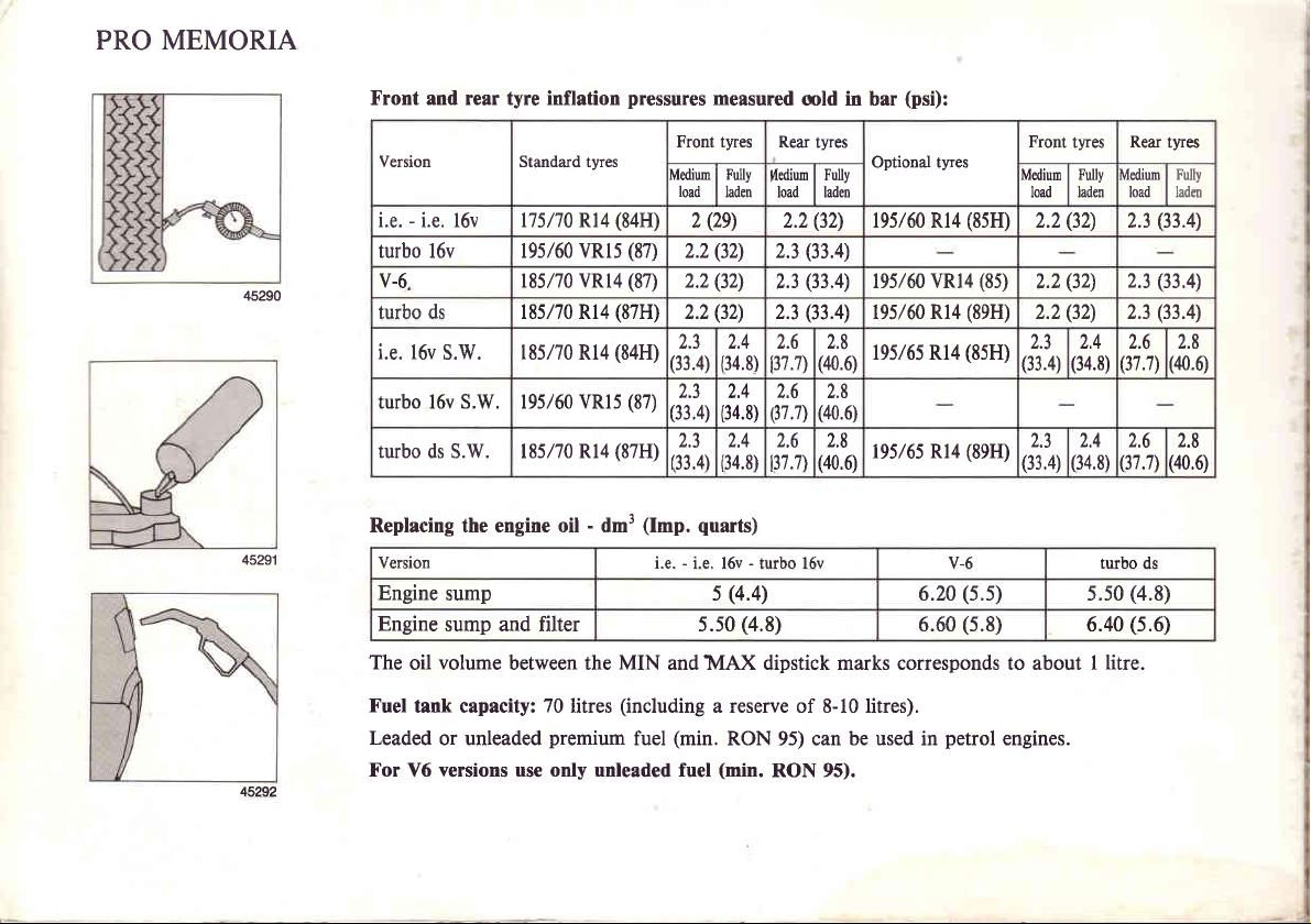
PRO MEMORIA
45290
45291
45292
(84H)
VRls
(87H)
(84H)
Rl4
(87H)
pressures
(87)
(87)
measured
Front tyres Rear
Mdium
load
(2e)
2
(32)
2.2
(32)
2.2
(32)
2.2
L.J
(33.4)
L.J
(87)
(33,4)
133,4)
(Imp.
quarts)
i.e. - i.e. l6v - turbo l5v v-6 turbo ds
Front and rear tyre inflation
Version Standard tyres
i.e. - i.e. l6v 175170 R14
turbo l6v 195/60
v-6, 185/70 VRl4
turbo ds 18s/70 Rl4
l.e. 16v
S.W.
turbo l6v S.W. 195/60 VRl5
turbo ds S.W. 185/70 R14
Replacing the engine oil - dm3
Version
Engine
sump s
185/70
Engine sump and filter 5.50
The
Fuel
Leaded
For
volume
oil
tank capacity:
or unleaded
versions use only unleaded fuel
Y6
between the MIN and MAX dipstick marks corresponds to about I
litres
(including
fuel
70
premium
a reserve of 8-10 litres).
(min.
Fully
vlediun
laden
load
2.3
2.3
2.3
1t
2.6
:34.8)
i37.7)
at
2.6
37.7)
34.8)
L.+
2.6
34.8)
"37.7\
(4.4)
(4.8)
RON 95)
(min.
RON 95).
old in bar
tyres
Fully
laden
(32)
2.2
(33.4)
(33.4)
(33.4)
2.8
(40.6)
2.8
(40.6)
2.8
(40.6)
be used in
can
(psi):
Optional tyres
195/60 Rl4
195/60 VRl4
195/60 Rl4
tgs/6sRl4
195/65 Rl4
(5.5)
6.20
(5.8)
6.60
petrol
(85H)
(85)
(89H)
(85H)
(89H)
engines.
Front
Mediun
load
(32)
2.2
(32)
2.2
(32)
2.2
(33.4)
2.3
(33.4)
Rear
tyres
Medium
Fully
laden
load
(33.4)
2.3
(33.4)
2.3
(33.4)
2.3
z.+
(34.8)76(37.7)
2.4
2.6
(34.8)
(37.7\
(4.8)
5.50
(5.6)
6.40
litre.
tyres
Fulb
ladeo
2.8
(40.0
2.8
(40.6)
Page 3
Dear
Sir
or
Madam,
'
Congratulations
The
owner
appreciate
You
should
driving
You
will
we
qrd
choice.
A
coupon
supplied
This
booklet
describes
We
are
drive
Regards,
it
the
learn
feel
along
the
sure
with
handbook
your
carefully
car for
further
you
booklet
also
terms
that
pleasure
on
choosing
car.
read
the first
will
be
for
with
the
includes
of
you
a LANCIA.
has
about
convinced
service
handbook
the warranty.
will
for
prepared
been
this handbook
time.
the features
you
schedule
the warranty
enjoy
many
your
years
to help
carefully
your
of
have
made
maintenance
certificate,
new
car,
to
come.
you
fully
before
Thema,
the right
which
and will
LANCIA
is
Page 4
Page 5
a
I
a
t
t
your
Driving
car
TABLE OF
CONTENTS
What
Maintenance
Body
Thema Station
Specifications
to do
maintenance
if...
and
Wagon
care
Page 6
Page 7
Page 8
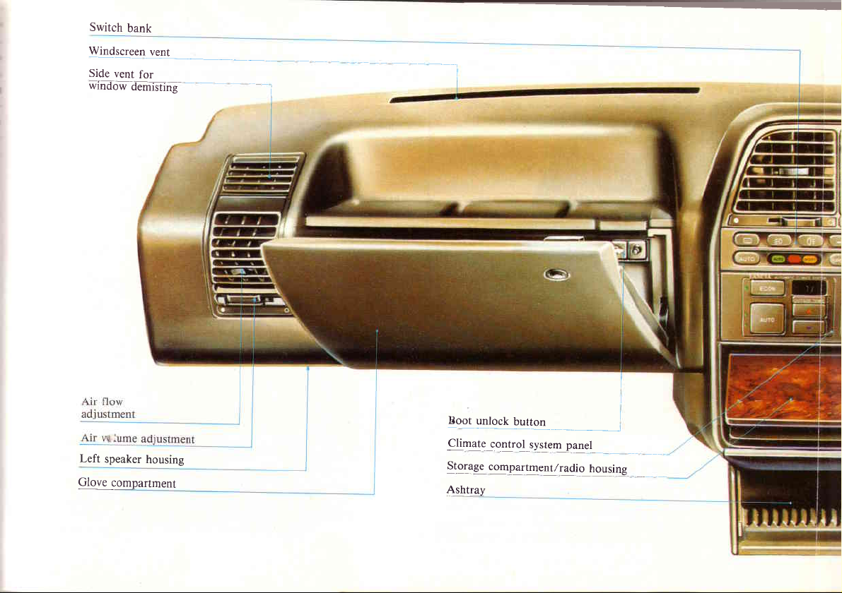
Switch
bank
Wr4$reqn-rgn!_
Side
vent
window
Left
Glove
for
demisting
speaker
housing
compartment
Boor
unlock
eliq4e
qIelage
cglqol
gggpartment/radio
Arbt14y
button.
slqeqp4qet
_.
housing
Page 9
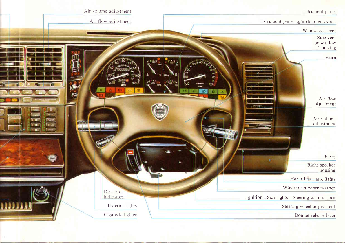
Air volume
Air 1'lou'
Dircction
in d icat ors
Cigarette
:rcljr:stment
adjustn.rent
Ertcrior
lights
lighter
lgnition
lnstrument
Side lights
Instrument
panel
light
dimmer
Windscreen
Right speaker
Hazarcl
Windscreen wiper/washer
-
Steering column lock
Steering wheel
Bonnet release
panel
srvitch
vent
vent
Side
window
for
demisting
Horn
Air
flow
adjustment
Air volume
adjustment
Fuses
housing
arning lights
adjustment
lever
Page 10
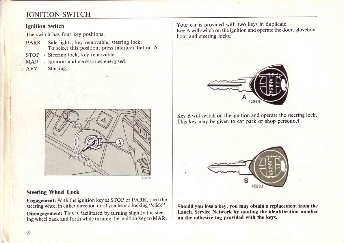
IGNITION
Ignition
The switch
PARK
STOP
MAR
AVV
Switch
has four
-
Side
To select
-
Steering
-
Ignition
-
Starting.
SWITCH
positions.
key
key removable,
lights,
position,
this
lock, key removable.
and accessories
steering
press
interlock button
energised.
lock.
A.
Your car
A will switch
Key
and
boot
provided
is
on the
steering
with two
locks.
ignition
keys in duplicate'
door,
and operate
the
glovebox,
Steering
Engagement:
steering
Disengagement:
ing
Wheel
wheel
wheel back
With the
in either direction
and
Lock
is facilitated
This
forth
ignition
key at STOP
until
while turning
you
hear a
by turning
the ignition
PARK, turn
or
locking
slightly
key to
the
"click".
the steer-
MAR.
will
Key B
This
Should
Lancia Service
on the adhesive
switch
key may be
you
lose a
the ignition
on
given
to car
you
key,
Network by
provided
tag
and operate
park
or
may obtain
quoting
the
with the
steering
the
personnel.
shop
a replacement
identification number
keys.
from the
lock.
Page 11
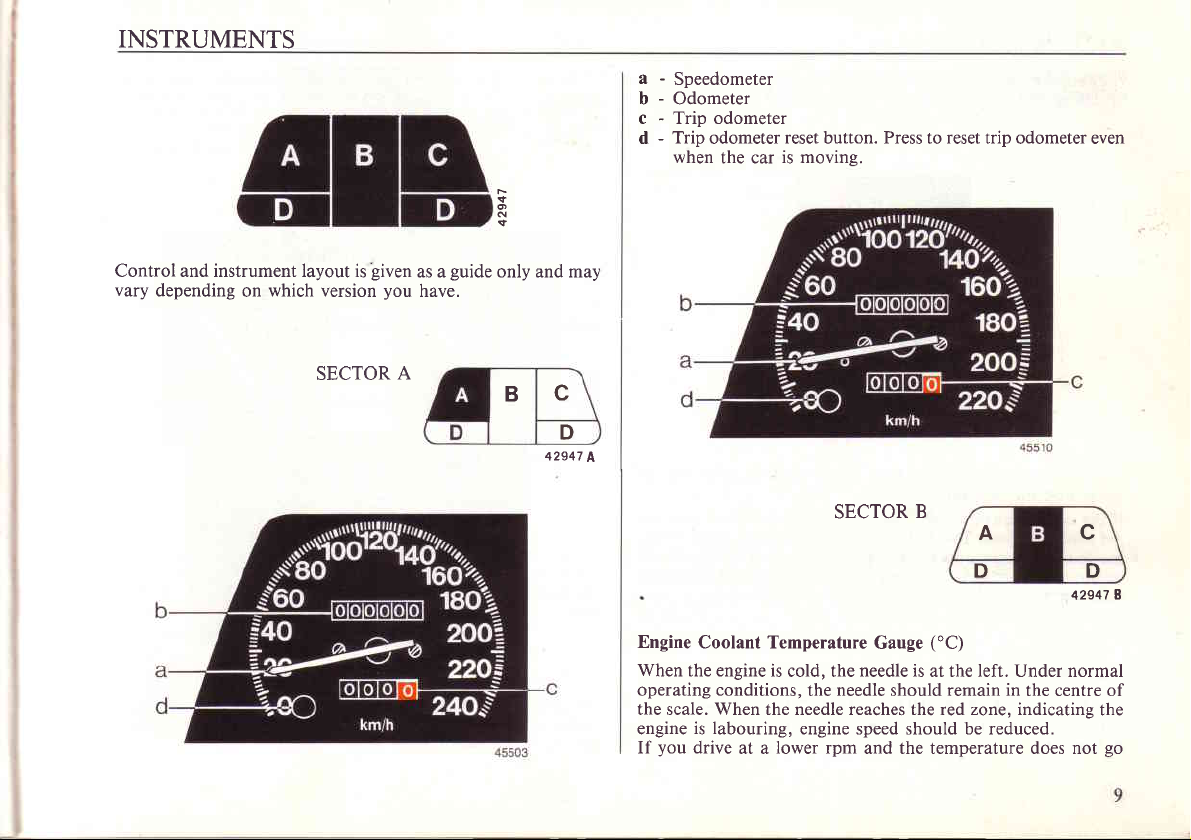
INSTRUMENTS
a-
Speedometer
b-
Odometer
c-
Trip odometer
d-
Trip
odometer
when
the car
F
{
d
reset
button.
is movine.
Press
reset
to
trip odometer even
Control and instrument layout is
vary
depending
which version
on
SECTOR
given
you
A
as a
have.
guide
only and may
c
B
D
42947
A
SECTOR
B
A
D
Engine
Coolant Temperature
When
the engine is
operating conditions,
the scale. When the needle reaches the red zone, indicating
is labouring,
engine
you
If
drive
at a
cold, the
lower rpm
needle is
needle
the
engine speed should be reduced.
and the temperature does not
("C)
Gauge
at the left. Under normal
should remain
in
the centre of
c
D
42947
I
the
go
Page 12
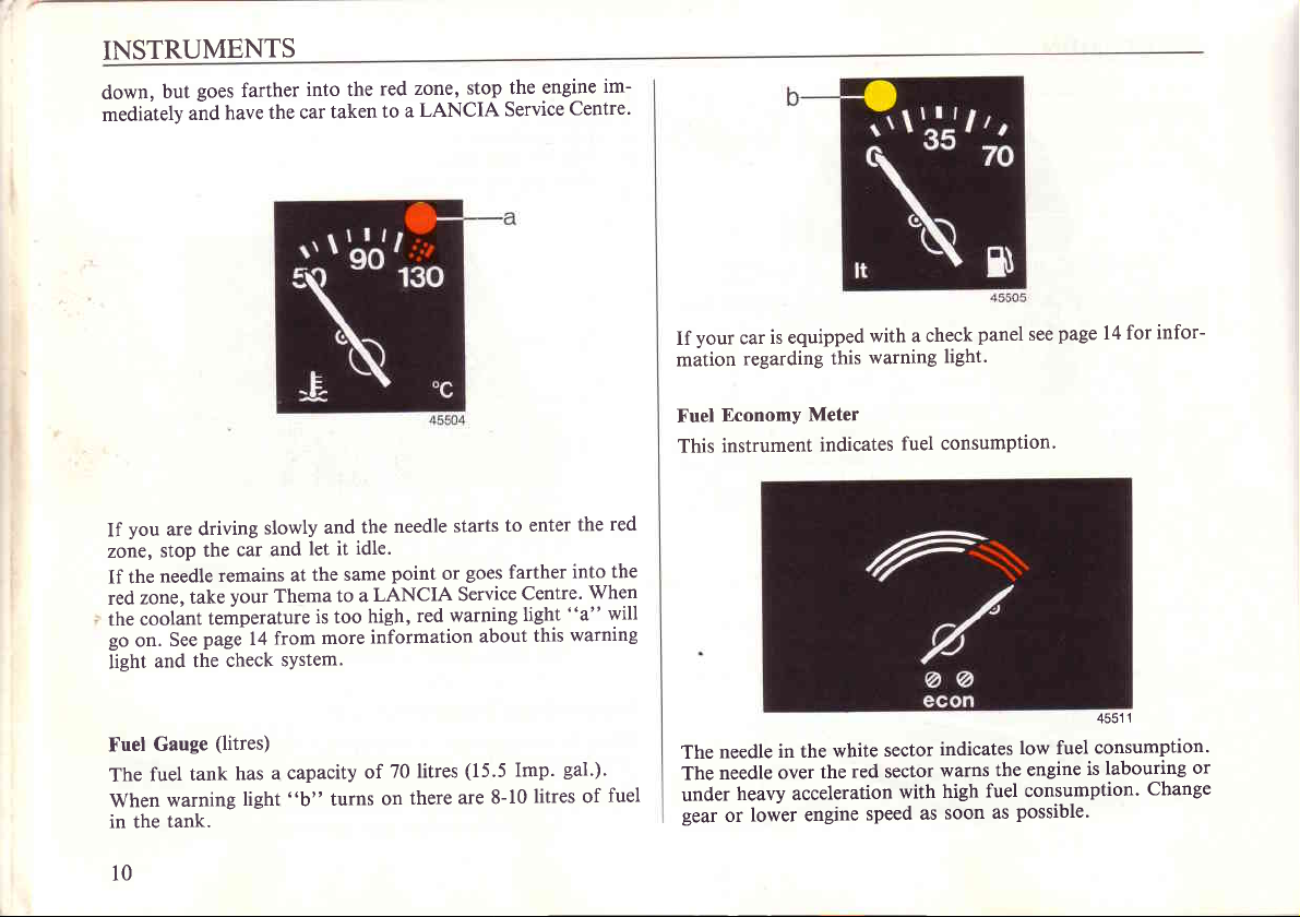
INSTRUMENTS
goes
and
farther
have
the car
but
down,
mediately
into the
taken
red
to
zone,
LANCIA
a
stop the
Service
engine
Centre'
im-
your
If
mation
is equipped
car
regarding
with a check
warning
this
light.
panel
see
page
I 4 for infor-
you
If
zone,
If the
zone,
red
coolant
the
go
on.
light
Fuel
The
When
in the
l0
driving
are
the
stop
needle
take
See
and the
Gauge
tank
fuel
warning
tank.
slowly
car and
your
at the
Thema
remains
temperature
page
14
check
(litres)
has
light
from
system.
a
capacity
"b"
and
let it
same
to a
is too
more
turns
needle
the
idle.
point
LANCIA
red
high,
information
70 litres
of
there
on
starts
goes
or
Service
warning
about
(15.5
are 8-10
to enter
farther
Centre.
light
this
gal.).
Imp.
litres of
red
the
the
into
When
"a"
will
warning
fuel
Economy
Fuel
instrument
This
needle
The
needle
The
heavy acceleration
under
gear
lower engine
or
Meter
in the
over
indicates
sector
white
red sector
the
speed
fuel consumption'
low fuel
the engine
fuel consumption.
possible.
as
with
as
indicates
warns
high
soon
1
4551
consumption'
labouring
is
Change
or
Page 13
INSTRUMENTS
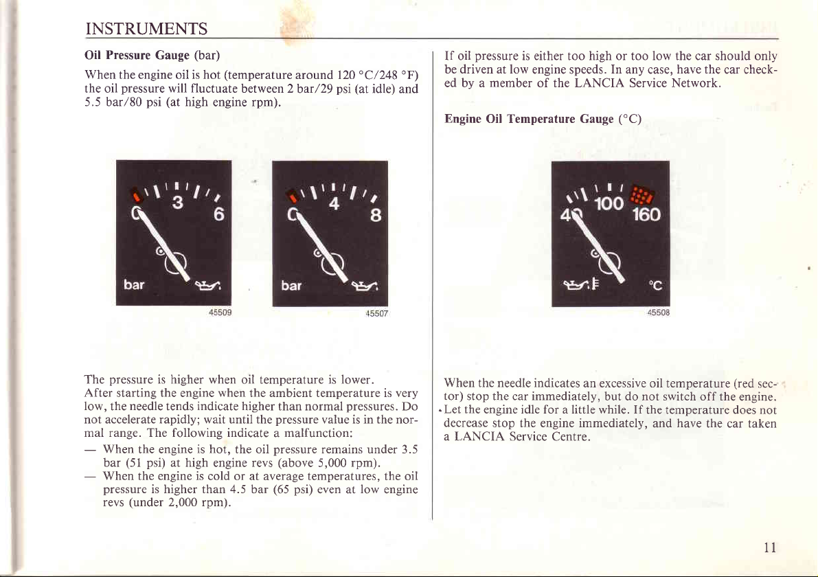
Pressure
Oil
When
the engine oil is hot
pressure
the oil
5.5 barl8O
The
After
low,
not accelerate rapidly; wait until the
mal range. The following indicate a malfunction:
-
When
bar
-
When the engine is
pressure
revs
psi
pressure
starting the engine
needle
the
the engine
(51
psi)
is higher than 4.5
(under
(bar)
Gauge
(temperature
will fluctuate
(at
high
engine
is higher when
tends
at high
2,000 rpm).
when
indicate
is hot,
engine
cold or at average temperatures, the oil
around 120'C/248'F\
between 2
bar /29
psi (at
rpm).
oil temperature is
the ambient temperature is very
higher than normal
the oil
revs
bar
pressure
pressure
(above
(65 psi)
value is in the nor-
remains under 3.5
5,000
even at
idle) and
lower.
pressures.
rpm).
low
engine
Do
pressure
If oil
be driven at low
ed by a
Engine
When
the needle indicates
tor) stop the car immediately,
.
Let
the engine idle for a little while. If
decrease
a LANCIA Service
is either too high or too low the car should only
member
Oil Temperature Gauge
engine speeds.
of the LANCIA Service Network.
an excessive oil temperature
stop the engine immediately,
Centre.
In
any case,
('C)
but do not switch off the
have the
the temperature does not
have
and
car check-
the car taken
(red
sec-
engine.
1l
Page 14
7:
INSTRUMENTS
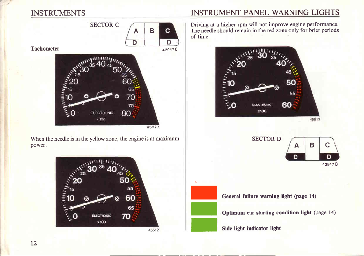
Tachometer
When the needle
power.
is in the
SECTOR
yellow
zone, the engine
C
AIB
DI
ID
is at maximum
42541
INSTRUMENT
Driving at a
The needle should
of time.
c
PANEL
higher rpm will
remain in the
SECTOR D
WARNING
not improve engine
red zone only
for
A
LIGHTS
performance.
periods
brief
B c
O
42947
t2
I
I
I
General
Optimum
Side
failure warning
light indicator
car starting
light
(page
light
condition
light
14)
(page
14)
Page 15
INSTRUMENT
PANEL
WARNING
LIGHTS
I
r
I
I
I
I
r
I
I
r
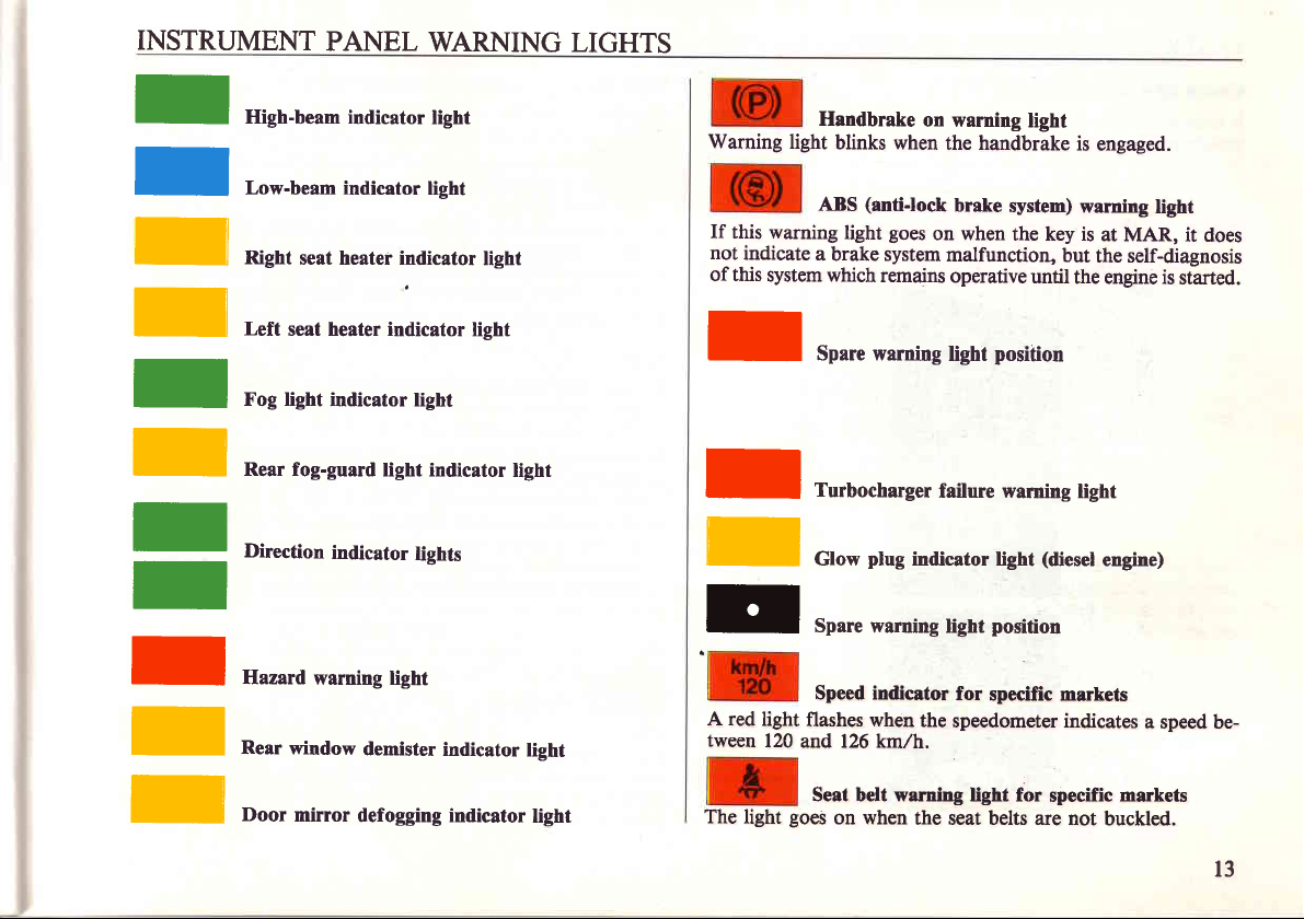
High-beam indicator
Low-beam indicator
Right
seat heater indicator
Left
seat heater indicator
Fog light
Rear fog-guard
Direction
Hazard
Rear window
indicator light
light indicator
indicator
warning light
demister
light
light
lights
indicator
light
light
light
light
Handbrake
Warning
If this warning
not
of this
I
I
f
r
A red
tween
light
indicate
system which
light
flashes when
120
and 126 km,/h.
ABS
a brake system
Spare warning
Turbocharger
Glow
Spare warning
Speed indicator
on warning
blinks when
(anti-lock
goes
light
remains
plug
indicator light
the
light
the handbrake
brake
system)
on when
malfunction,
operative
position
light
failure warning
position
light
for
specific markets
speedometer indicates
is
warning
the key is
but
until
the engine is
light
(diesel
engaged.
the self-diagnosis
light
at MAR,
engine)
a speed be-
it does
started.
I
Door
mirror
defogging indicator
light
The
light
Seat belt warning light for
goes
on when
the seat belts are not
specific
markets
buckled.
l3
Page 16
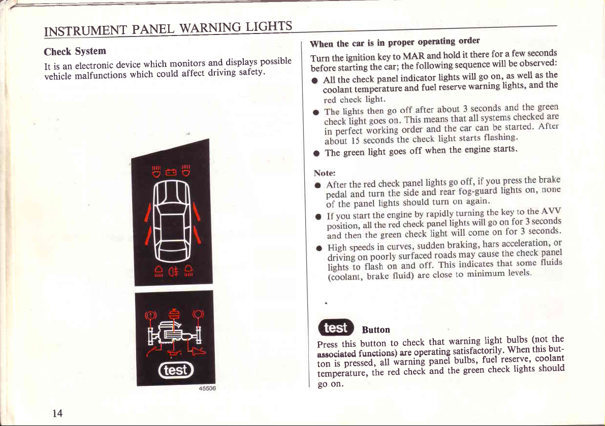
INSTRUMENT
Check
It
;hi.l;
System
electronic
an
is
-uiiun.tiont
device
PANEL
which
could
which
WARNING
affect
and
driving
monitors
LIGHTS
displays
safetv'
possible
is
car
the
When
ignition
the
Turn
#i;iesffiifiirtidu.;
check
the
AII
o
coolant
O
The
temperature
green light
proper
in
to
key
panel
goes
operating
and
MAR
following
the
indicator
ruet
ana
when
off
hold
sequence
lights
.Jr.ru.
the
order
there
it
will
warning
engine
for.a
will
go.on'
starts'
seconds
few
be observed:
as
well
as
and
lights,
the
the
t4
this
Press
urr*i"t.A
;#i,
ilt;il""u
ffi;;*:;;;,
go
on.
Button
button
functions)
to
i"*"iite
ied
,t"
check
operating
are
checl
warning
that
satisfactorily'
punti b"lbt'
green check
the
and
light
fuel
(not
b-ulbs
this^but-
When
reserve'
lights
the
coolant
should
Page 17
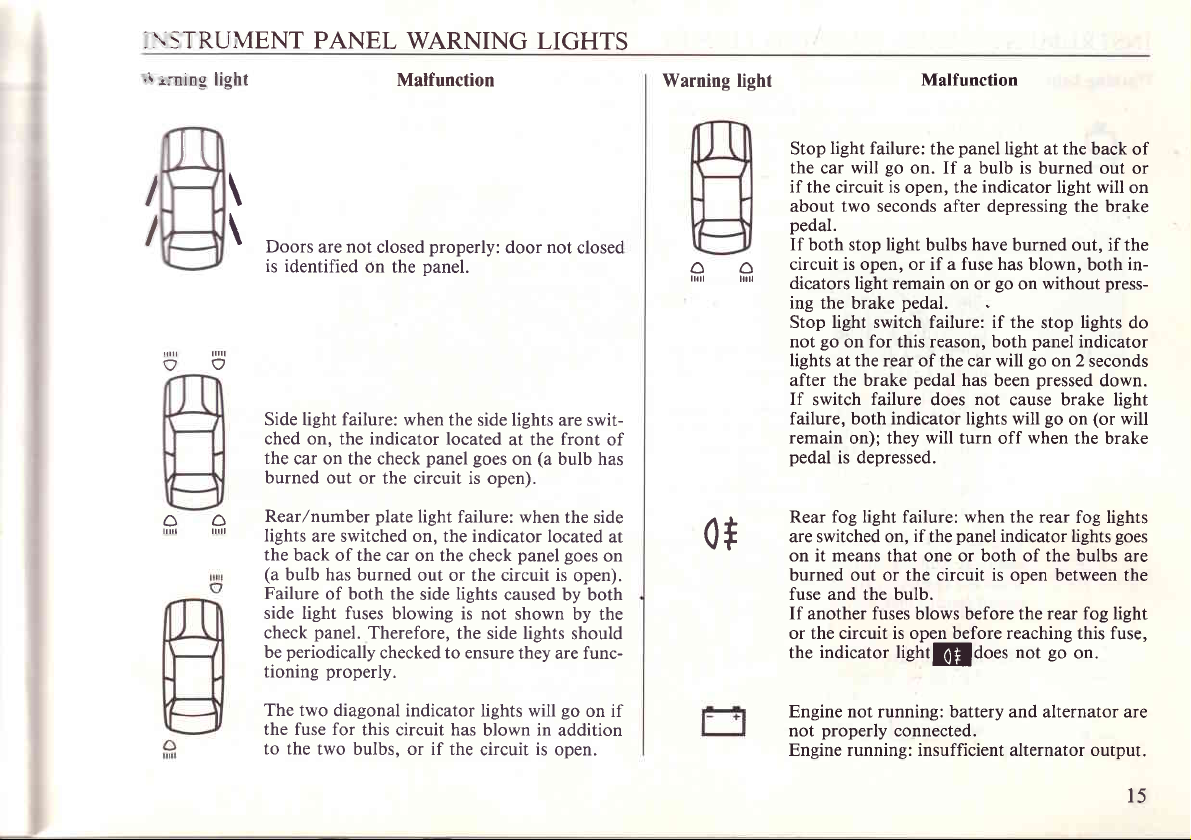
.\STRUMENT PANEL
.r
ining light
WARNING LIGHTS
Malfunction
Warning light
Malfunction
I
I
-
JI
I
\
\
ilil1
I
Doo.,
is identified
Side light failure: when
ched on. the indicator
the
burned out
Rear/number
Iights
the
(a
Failure
side light fuses
check
be
tioning
The two
the fuse for
to the
not
are
on the
car on the check
back of the car
bulb has burned
periodically
or the circuit is open).
are switched on, the indicator located
of both the
panel.
Therefore,
properly.
diagonal indicator lights will
this circuit has
two bulbs, or if the
properly:
closed
panel.
the side lights
located
panel goes
plate
light failure: when
on the check
out or the circuit is
lights
side
blowing is not
checked to ensure
the side lights
blown
circuit
not
door
at the
on
caused by both
closed
are swit-
front
(a
bulb has
the side
panel goes
shown by the
they are func-
in
is
open).
should
go
on if
addition
open.
on
light failure:
Stop
the car
if
the circuit
about
pedal.
If
both stop
oo
lfttl
of
at
0t
circuit is open, or if a fuse has
xrl
dicators light remain
ing
the brake
Stop light switch failure: if the
go
not
lights at the rear of the car will
after the brake
If
switch
failure, both indicator lights will
remain
pedal
Rear
are switched on,
on it means that one or both of the bulbs
burned out or the circuit is open between
fuse and the bulb.
If
another
or the circuit is open before reaching this fuse,
indicator lieht@does not
the
Engine not running: battery and alternator are
properly
not
Engine running: insufficient alternator output.
go
will
is
two
seconds after depressing the brake
light
on for this reason, both
failure
on); they
is depressed.
fog light failure: when
fuses
connected.
panel
the
on. If a bulb is burned
open, the
bulbs
pedal.
pedal
does
will
if
the
blows before the
light at the
indicator
have
burned out, if the
go
on or
has
been
not
cause brake light
turn off
the rear fog lights
panel
indicator lights
light will
blown, both
on without
stop
panel
go
on 2
pressed
go
when
rear fog light
go
back of
out or
press-
lights
indicator
seconds
down.
(or
will
on
the brake
goes
are
the
on.
on
in-
do
l5
Page 18
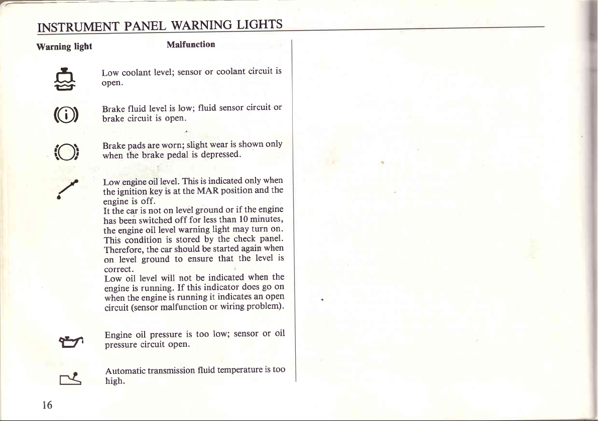
INSTRUMENT
Warning
light
f,
er
(e)
Low
open.
Brake
brake
PANEL
fluid
circuit
level; sensor
level
coolant
WARNING
Malfunction
low; fluid
is
is open.
LIGHTS
or coolant
sensor
circuit
circuit
is
or
,:O}
./
v
16
pads
Brake
the
when
engine
Low
ignition
the
is off.
engine
It
has
the
This
Therefore,
on
correct.
Low
engine
when the
circuit
Engine
pressure
Automatic
high.
car
ihe
been
engine
condition
level
oil
is
(sensor
is not on
switched
level
running.
oil
circuit
worn;
are
brake
Pedal
level.
oil
is at
key
lev6l
off
warning
level
oil
is stored
should
car
the
ground
engine
to
not be
will
If
is running
malfunction
pressure
open.
transmission
wear
slight
is dePressed.
is indicated
This
the
for
ensure
this
is too
position
MAR
ground
less than
light
the
by
be started
that
indicated
indicator
indicates
it
wiring
or
low; sensor
temperature
fluid
is shown
only
if the
or
l0 minutes,
may turn
check
again
the
when
does
problem).
only
when
and
engine
panel.
when
level
go
open
an
or
is too
the
on'
is
the
on
oil
Page 19
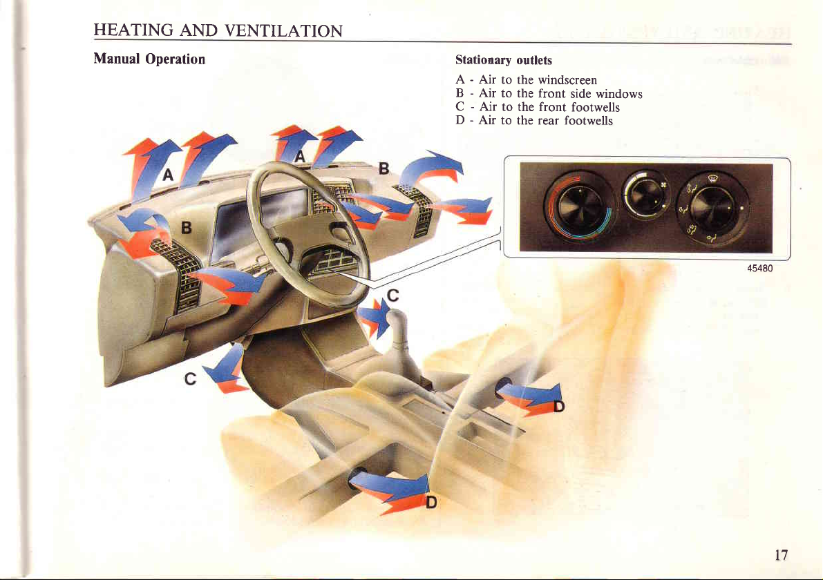
HEATING
AND
VENTILATION
Manual
Operation
Stationary
A - Air
B - Air
C - Air
D
to the windscreen
to
to the front
-
Air
to the rear footwells
outlets
the front
side windows
footwells
45480
t7
Page 20
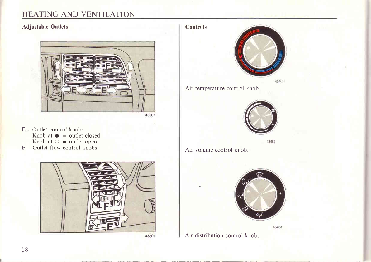
HEATING
AND VENTILATION
Adjustable Outlets
-
Outlet control knobs:
E
Knob at
Knob
-
Outlet flow control knobs
F
O : outlet closed
at O : outlet open
Controls
Air temperature
Air volume
control
control
knob.
knob.
t8
Air distribution
control
knob.
Page 21
HEATING
AND
VENTILATION
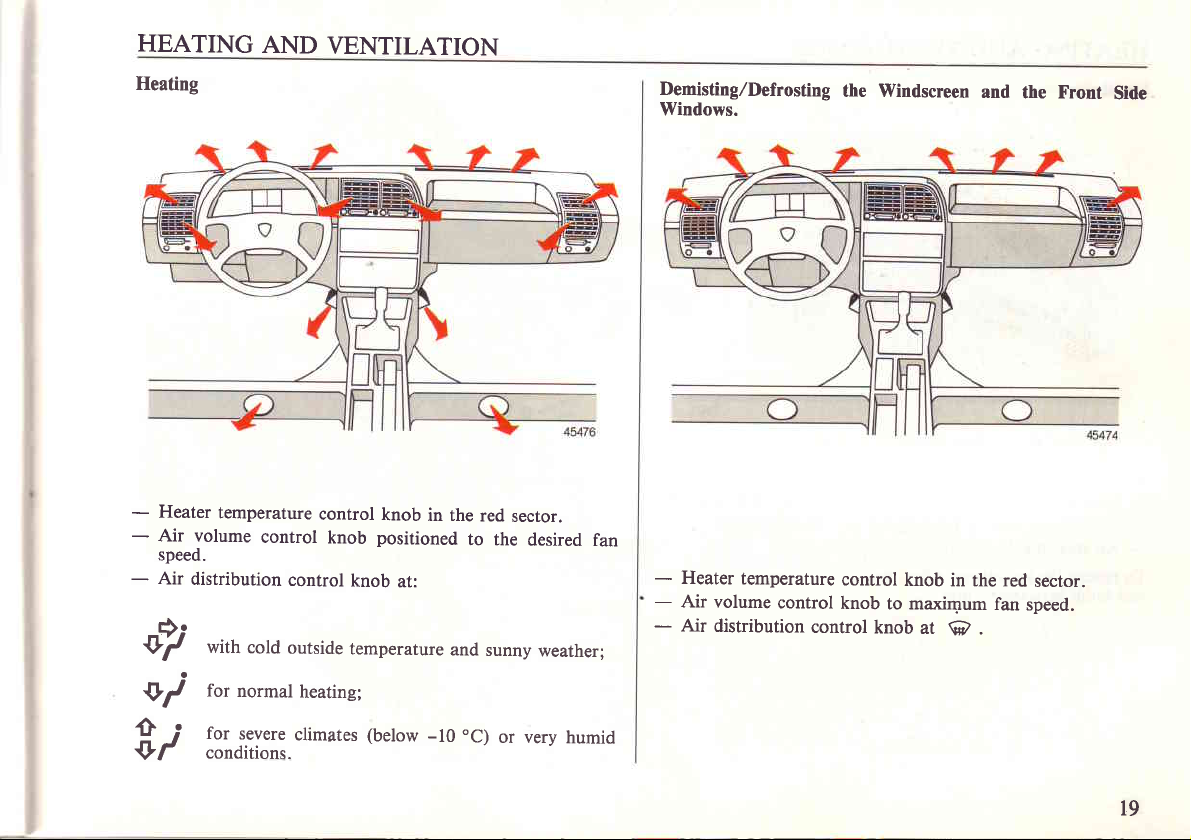
Heating
-
Heater
-
Air volume
speed.
-
Air
distribution
v7
temperature
control
with
cold
control
knob
control
outside
knob
in the
positioned
knob
at:
temperature
to the
and
red
sector.
sunny
desired
weather;
fan
Demisting,/Defrosting
Windows.
-
Heater
-
-
temperature
Air volume
Air
distribution
control
control
the Windscreen
control
knob
knob
in the red
to maximum
knob
at
@
and
fan
.
the Front
sector.
speed.
Side
+i
ii
for
normal
for
severe
conditions.
heating;
climates
(below
-10
"C)
or very
humid
t9
Page 22
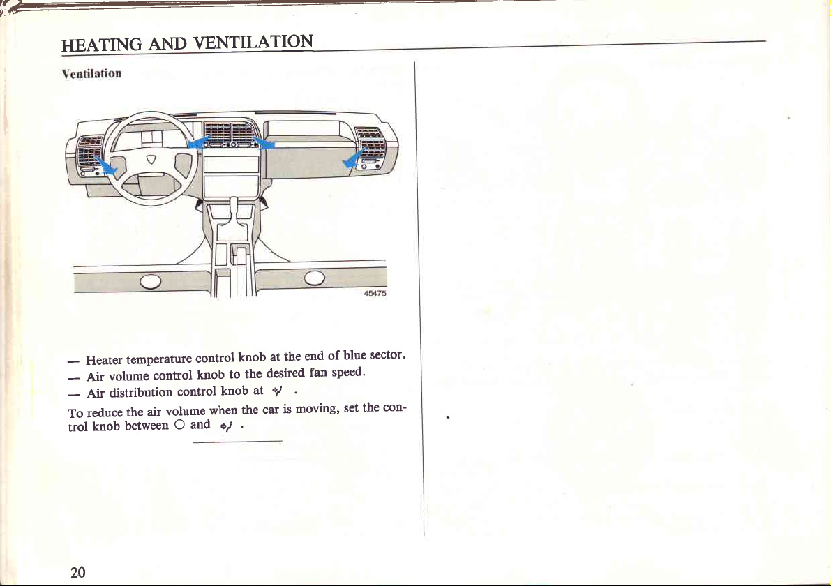
HEATING
AND
\ENIILATION
i
t
sector'
blue
of
end
the
at
knob
when
knob
to
knob
+7
the
the
.
desired
+l
at
car
moving,
is
fan
speed'
set
the
con-
-
-
To
trol
Heater
volume
Air
distribution
Air
reduce
knob
temperature
control
control
volume
air
the
between
O
control
and
20
Page 23
HEATING
AND
VENTILATION
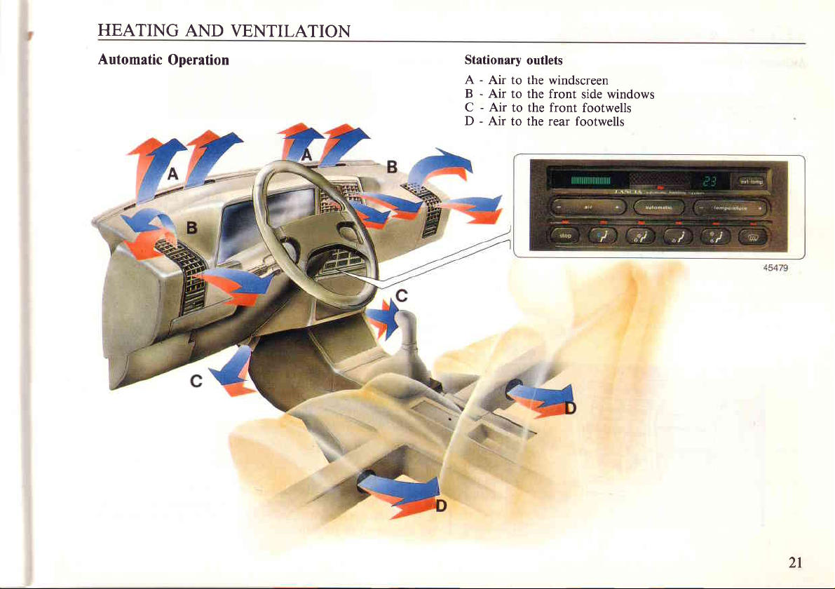
Automatic
Operation Stationary
-
A
Air to
B - Air
C - Air
D - Air
to the front
to the front
to the rear
outlets
the windscreen
side windows
footwells
footwells
2l
Page 24
HEATING
AND
VENTILATION
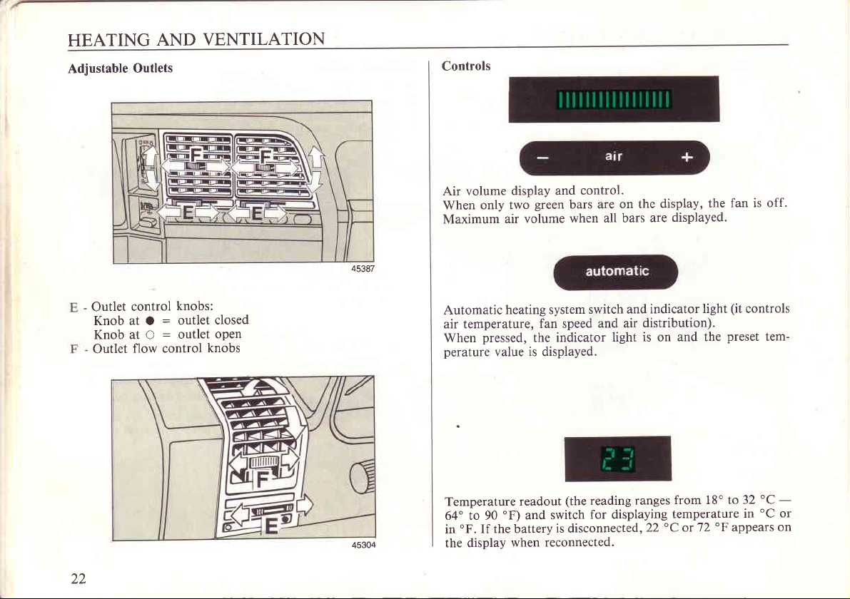
Adjustable
Outlet
Knob at O
Knob at O
Outlet
Outlets
control
:
:
control
flow
knobs:
outlet
outlet
closed
open
knobs
45387
Controls
Air volume
When
Maximum
Automatic
air temperature,
When
perature
display and
only two
volume
air
heating system
pressed,
value is displayed.
green
bars are
when all bars
fan speed
indicator
the
control.
on the
switch and
and air
light
display,
displayed.
are
indicator
distribution).
is
on
light
and the
fan is off.
the
(it
preset
controls
tem-
22
45304
Temperature
64" to 90
'F.
in
the display
oF)
If the battery
readout
and switch
reconnected.
when
(the
reading
for displaying
is disconnected,22
ranges
from 18'to
temperature
"C
or'12
"F
'C
32
oC
in
appears
or
on
Page 25
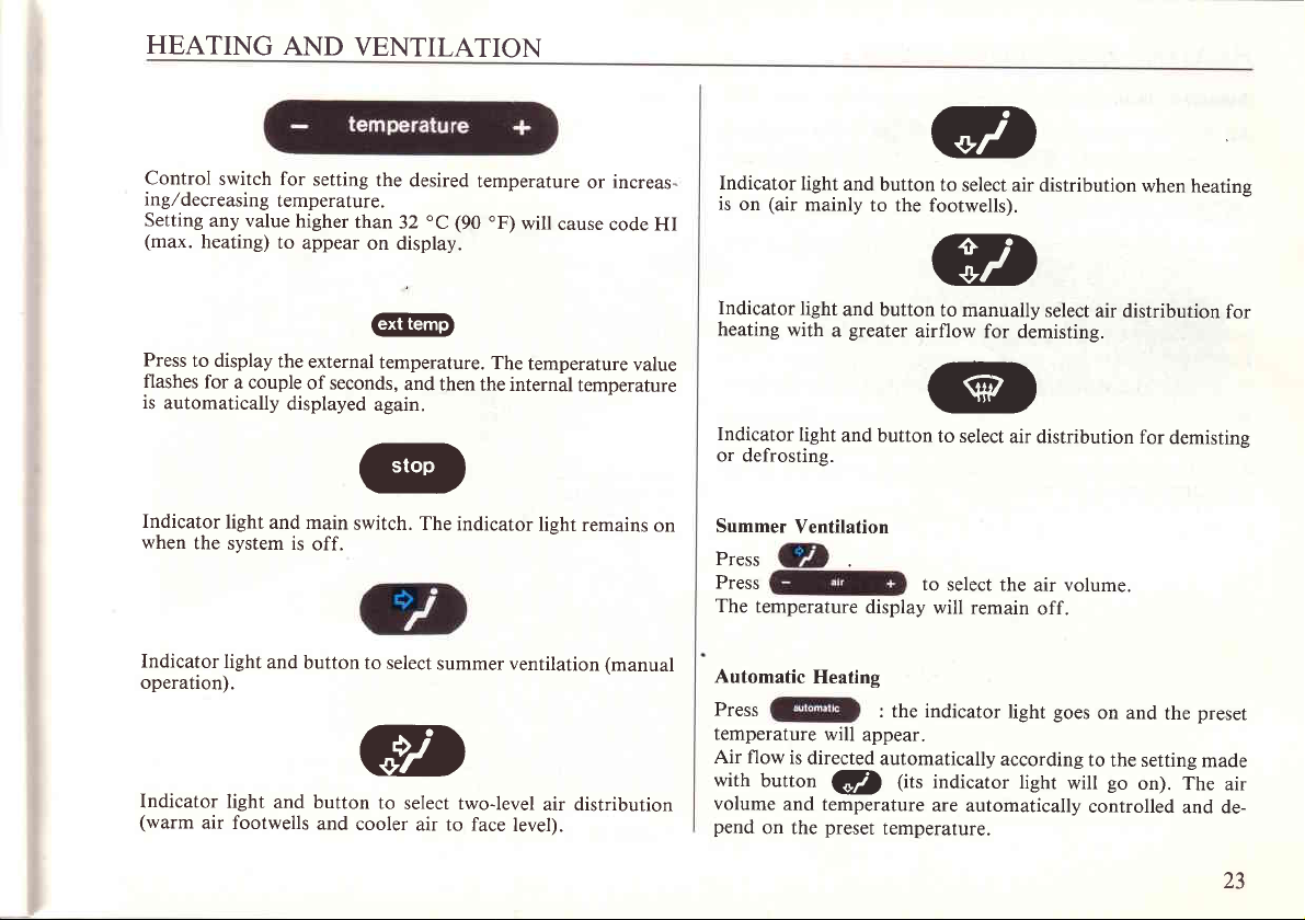
HEATING
Control
ing,/decreasing
Setting
(max.
Press
flashes
is
Indicator
when
switch for
any value
heating)
to display
for
light
the
system is
a couple
automatically
AND
temperature.
to
the
displayed
and main
VENTILATION
setting
higher
than
appear
external
of seconds,
switch. The
off.
the
desired
"C
32
on display.
@
temperature.
and
again.
ry
temperature
(90.F)
The
then
the internal
indicator
or
will
cause
temperature
temperature
lisht
remains
increas-
code HI
value
on
Indicator
is
Indicator
heating
Indicator
or defrosting.
Summer
Press
Press
The
light
(air
on
mainly
light
with
light
Ventilation
temperature
and
button to
to the
and button
greater
a
and button
display
gt
select air
footwells).
4n
-z-
to manually
airflow
^JL,
Iit
to select
to
select the
will remain
distribution
select
for demisting.
air distribution
volume.
air
off.
when
heatine
air distribution
for
demistine
for
Indicator
operation).
Indicator
(warm
air footwells
light
light
and
button
and button
and
to select
ath
=q,-
to
select two-level
cooler
air to face
summer ventilation
air distribution
level).
(manual
Automatic
Press
temperature
Air flow
with
volume
pend
is
button
and
on the
directed
Heating
: the indicator
will
appear.
automatically
(U)
temperature
preset
tir.
temperature.
goes
light
according
indicator
are automatically
lighr
will
on and
to
the setting
go
on). The
controlled
the
and de-
preset
made
air
23
Page 26
T-
HEATING
Automatic
flow can be
Air
and
cold
low and
is also
It
volume
manual adjustments
If
are made the
volume
indicates
remains
display
the temperature
If
letter
the
operation
distributes
AND
heating with
directed by
Press
sunny.
to increase
rapidly demist
to
possible
pressing
by
system operation
unchanged because
"E"
will appear
is automatic;
fresh air.
VENTILATION
manual adjustments
pressing
lf
outside temperature
ISD
windscreen
to change
modifying air distribution
selected
the
tne
demisting
or defrost
the automatically
indicator
is no longer
the
lower
is
on the
than
display
heating is turned
weather is
,f the
@
while driving.
the windscreen.
selected
andlor air
light will
fully automatic.
heating system
the outside
indicating that system
go
is still on.
temperature
off and the system
is very
air
off.
Press
flow
This
The
24
Page 27
AIR
CONDITIONER
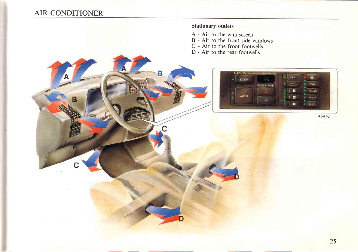
Stationary
A - Air
B - Air
C - Air
-
D
outlets
to the windscreen
to
the front
to the front
Air
to the rear
side windows
footwells
footwells
BA
45478
\
25
Page 28
AIR CONDITIONER
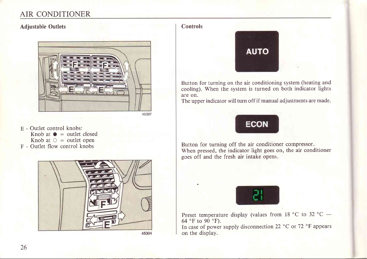
Adjustable Outlets
-
Outlet
Knob
control
:
at
O
Knob at O : outlet
-
Outlet
flow control
knobs:
outlet closed
open
knobs
Controls
Button for turning on the
cooling).
are on.
The upper
Button for turning
When
goes
When the system
indicator will turn off
pressed,
off and
the
the fresh air
off the air
indicator
air conditioning
is turned on
if manual adjustments
conditioner
goes
light
intake opens.
on,
(heating
system
both indicator
are made.
compressor.
the air conditioner
and
lights
26
45304
Preset temperature
'F
64
In case of
on the
to 90
power
display.
'F).
supply
display
(values
disconnection
from 18
"C
22
'C
or
to 32'C
'F
72
-
appears
Page 29
AIR
CONDITIONER
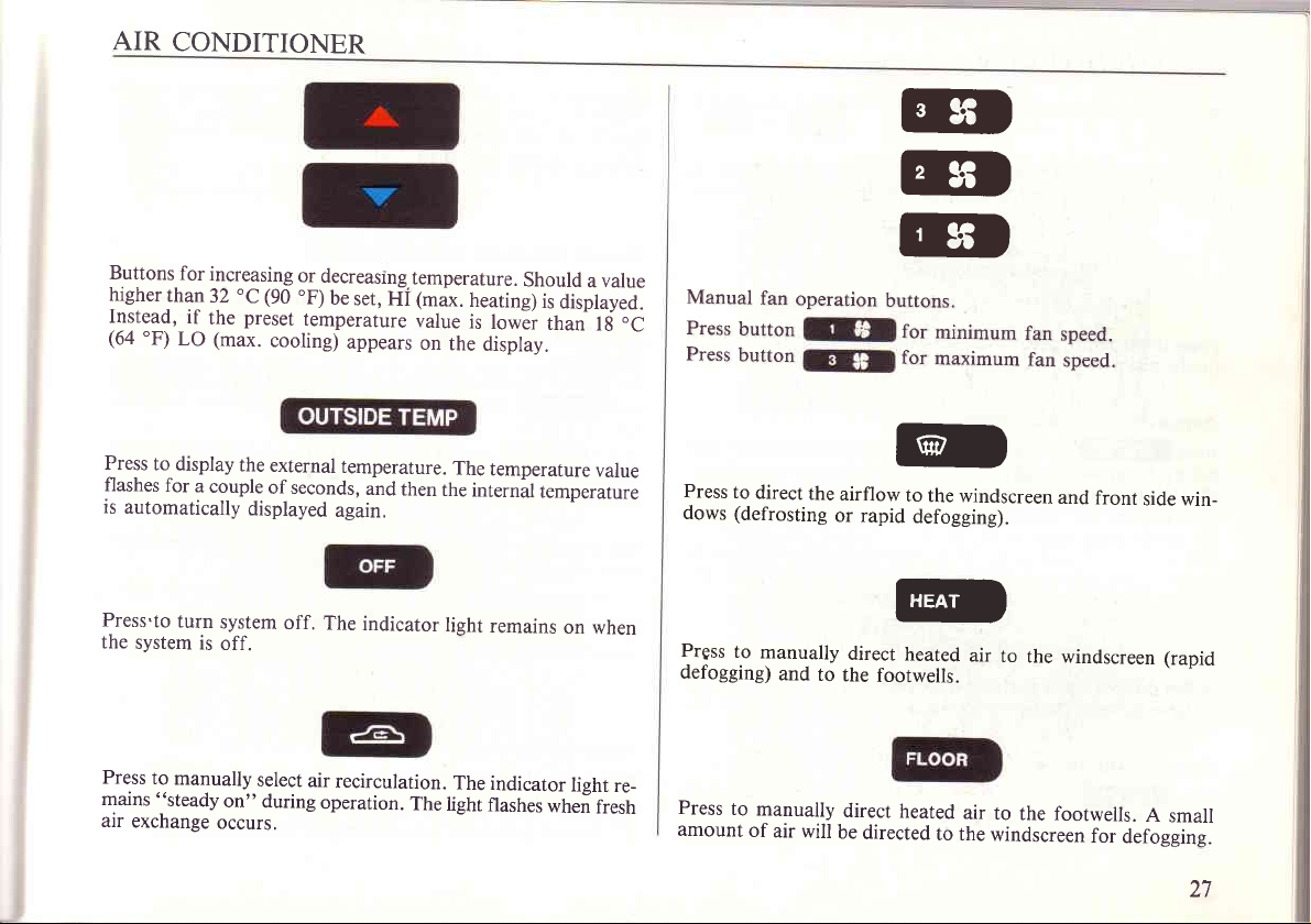
Buttons
higher
I!rt910,
(64
"F)
for
than
if
LO
increasing
3.2
the
(max.
'C
(90
preset
cooling)
or
decreasrng.temperature.
.F)
be
set,
remperature
Hi
appears
1max.
value
on
the
heating)
is
display.
Should
lowEr
value
a
is
displayed.
than
lti.C
Manual
Press
button
Press
button
fan
operation
rr
rf
rf
buttons.
for
minimum
for
maximum
fan
fan
speed.
speed.
Press
to
flashes
is
Press.to
the
Press
mains
air
display
for
automatically
turn
system
to
manually
'steady
exchange
the
a couple
displayed
system
is
off.
on"
occurs.
external
of seconds,
off.
The
select
air
during
operation.
temperature.
and
then
again.
indicator
recirculation.
The
The
the
light
The
light
internal
temperature
temperature
remains
indicator
flashes
on
light
when
value
when
re_
fresh
Press
to
direct
(defrosting
dows
Prgss
to
defogging)
Press
to
amount
of
the
manually
and
to
manually
air will
airflow
or rapid
direct
the
footwells.
direct
be
directed
GD
to
the windscreen
defogging).
@
heated
air
heated
air to
to the
and
to
the windscreen
the
footwells.
windscreen
front
for
defogging.
side win_
(rapid
A
small
27
Page 30
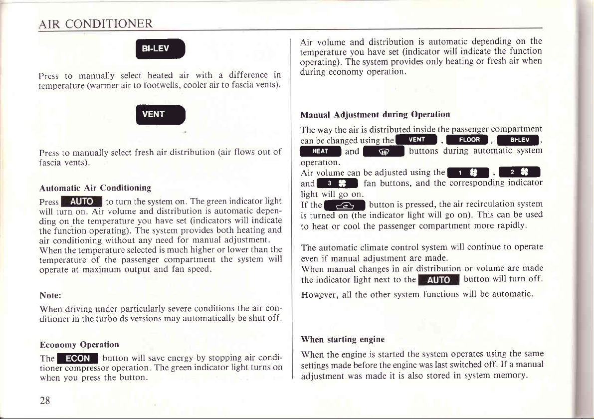
CONDITIONER
AIR
manually select
to
Press
temperature
(warmer
@
heated
to footwells, cooler
air
with a difference
air
air to
fascia
in
vents)'
volume and distribution
Air
temperature
operating).
during
you
The system
economy
have set
operation.
is automatic
(indicator
provides
only
depending
indicate the
will
heating or
function
fresh air
on
when
the
manually select
to
Press
vents).
fascia
Air
Automatic
Press
turn on.
will
ding on.the
funciion
the
air conditioning
When the temperature
temperature
operate
Note:
driving under
When
ditioner
Economy Operation
fh.
EGEII
cornpressor
tioner
you press
when
Conditioning
turn the system
to
Air volume and
temperature
operating).
without any
the
of
maximum output
at
particularly
in the turbo
ds
button
operation.
the button.
28
ID
fresh air
you
The system
selected
passenger
versions may automatically
will save energy
distribution
green
The
on.
distribution
have set
need
is much higher or
compartment
fan speed.
and
severe
green
The
is automatic
(indicators will indicate
provides
for manual adjustment.
conditions
by stopping
indicator
(air
flows out of
indicator light
heating
both
lower than
system
the
the air conbe shut
air condi-
light turns on
depen-
and
the
will
off.
Manual
The
can be changed
]![
operatlon.
Air
andtrFl
light
If
is
to
The automatic
even
When
the
Howpver, all
When slarting engine
When the engine
settings
adiustment
Adjustment during
way the air is distributed
usins
und
rel
volume can be adjusted
fan buttons,
go
will
the
turned
heat or cool the
if manual adjustment
indicator light
on.
lzll
on
manual changes
made
button
(the
indicator
climate control
next to the
the other system
is started
before the engine
was made
Operation
inside the
thelE!il
buttons
using
and
pressed,
is
will
light
passenger
compartment
system
made.
are
in air distribution
functions
the system
was last switched
it is also stored
passenger
,
@!l|
during automatic
th.El
the corresponding
the air
go
on).
will
operates
in system
compartment
,
]@,
,

S\\'ITCHES
AND
CONTROLS
Erterior Lights
l:e erterior lights
\I
\R.
P:11 the
:;adlights
$r !_ights.
El
stalk towards the steering
(indicator
Turn the knurled
(also
see
can be turned on
light
part
p.
8).
when
the ignition key is at
wheel
to flash the high-beam
turns on).
of the stalk
from
Low-beam headlighls,
Turn
the knurled
part
of the stalk from
El'o@-
!l
High-beam
wards.
headlights.
When at
!ftfl.ou.
the stalk down-
\\
hen in this
position
the stalk cannot
moved down.
be
The
stalk
cannot
turned when in this
be
position.
l9
Page 32

SWITCHES
Direction Indicators
The direction indicators
MAR.
up
Lever
down
Lever
The direction
wheel returns to the straieht
AND
:
right turn
:
left
indicators are
CONTROLS
will only operate
indicators
turn
indicators
self-cancelling
position.
ahead
when
when the steering
the
45308
key is at
The intermittent
by turning the
wiper speed can be adjusted
knurled
part
the stalk.
of
45309
on some
versions
Windscreen
The windscreen
tion
O:OFF
I : Intermittent
:
2
:
3
Pull the stalk
screen
Wiper,/Washer
key is
Low
High speed
MAR.
at
speed
towards the steerins
washer.
30
wiper/washer will only operate
operation
*
wheel to actuate the
when the
igni-
wind-
Headlight Washers
Whenever the
operate
wiper
The
screen.
for
blades
a couple
windscreen
automatically
(if
fitted)
washer is used the
of seconds.
headlight
return to the base
45310
washers
of the wind-
Page 33

SWITCHES AND
CONTROLS
Hazard.Warning
A
Press
tion indicators
Instrument
Turn the knurled
instrument
to turn the hazard
and
Pannel Dimmer
panel
Flasher
repeaters
thumbwheel
light intensity.
warning lights
flash).
on the
steering column
on
(all
the direc-
to dim the
Rear window
Press
to defrost
Fog light
Press to
at MAR).
Rear
Press
or fog lights
Centralised
switch
turn on the fog lights
fog-guard light
to turn
defogger
switch
INNI
-
or defog the rear window.
(if
fitted)
@
(side
switch
@
on rear fog-guard lights
are already
power
lock
on
switch
(key
(doors,
lights
on and ignition
when
at MAR).
either the low
boot and fuel filter
key
beam
door)
JI
Page 34

SWITCHES
fuel
power
filter door
Centralised
Power
AND CONTROLS
door
unlock
unlock
switch
switch
INDIVIDUAL
Important
malfunction
If a
is automatically
setting
warning light turns
red
a
buttons.
SPORT
When the SPORT
is
selected
Steering
occurs
Button
(versions
at all speeds.
Wheel
Rake
SETTINGS
damper
in the
selected
mode
(as
on between
with damper
is
operative
Adjustment
control
if SPORT
the two
control system)
harder damper
a
system,
were selected)
AUTO
the
and SPORT
harder
and
setting
A cable
the
AUTO
When the
automatically
and
fitted
filler door
fuel
Button
driving
AUTO
-) /.
with a ring
manually.
(versions
mode
"comfort"
selects
style.
in
located
with damper
is
operative
or
boot can
the
control
the
"sport"
damper
depending
be used
system)
control
to open
system
on speed
Pull the
justments.
the
lever towards
lever forward
When
you
have
to lock
steering
the
found
the steering
wheel to
a comfortable
make
wheel in
vertical ad-
position
place.
N
push
Page 35

I}TDIVIDUAL
SETTINGS
Vrnual
For fore-and-aft
:he desired
Seat backrest
To adjust
irs necessary.
To modify
(if
Power front
The height,
can be
front
position.
the seat height,
seat back wrap-around
flitted).
seat adjustment
backrest angle,
adjusted when
seat
angle can
adjustment
adjustment,
Release
be adjusted
pull
and for-and-aft
the key
lift
lever
the lever
out telescopic
(if
is
A and
to lock
using knob
configuration
fitted)
at MAR.
slide the
the
B.
lever
C and operate
turn knob D
position
seat to
mechanism.
of the seat
Press
cJr
Press
Jrto
Press
$t
Power
seats
This device
backrest
The
when
people
console
angle,
position
desired.
can
next
to
adjust fore-and-aft
adjust
backrest
to adjust
with
(key
set can be
be stored. The
to the
seat height.
position
at MAR)
and for-and-aft
stored in the device's
Information
seats.
angle.
memory
allows
regarding
power
position.
fitted)
Gf
you
position
seat buttons
to
of the
memory
seat
45450
adjust
the height,
seat.
and recalled
position
are located
for three
on the
33
Page 36

INDIVIDUAL
SETTINGS
Adjustment
Press
.-t+
Jt
Pr.ss
j
e.ess
position
Seat
MEMO
Press
I
about
The
is no
seat
Seat
The seat
or closed.
second
positions
seat
longer
position
position
position
to adjust fore-and-aft
to adjust backrest
to adjust
supplied
information automatically
seat height.
memory
one of the three
and
to store seat
remain
(e.g.,
recall
be recalled either
can
angle.
position
permanently
battery
position.
recall
buttons
information.
in memory even
replacement). Storing new
cancels the
when
(1,
previously
door is
the
2, 3) for
power
if
open
set.
If the door is open,
o
position
seat
programmed.
as
When the door is
o
your
seat
Rear
Power seat adjustment
Move the
F - Button for adjusting the seat backrest
as right fore-and-aft
G - Button for adjusting the seat
as left
When either of the
retracts to facilitate settins
position (1,2,3).
seat
reaches the
seats
key
to the
fore-and-aft
quickly press
desired.
The seat
press
closed
position programmed.
(if
fitted)
position.
MAR
positioning.
positioning.
rear
doors
into the car.
the button
will
automatically
the button
Hold the button
backrest angle at the
is opened the corresponding seat
(1,
2,
for the
3)
position
corresponding
down until the
angle at the same time
itself
to
same time
J+
1A
Page 37

INDIVIDUAL
SETTINGS
Headrests
Front
Both
the height
:eadrests
:rrt vOUf
Rear
The rear
nprove
;orresponding
remains
:he headrest
should be
D€Ck.
headrests normally
visibility.
if
up
and angle
headrest
the occupant weighs
will lower into
ofthe headrests
positioned
When
one of the
automatically
to
remain
the flush
support the
more
can
with
flush
rear
doors is
comes into
than 25 kg.
position.
be adjusted. The
back of
your
the rear self
opened, the
position
Otherwise,
head,
tcr
and
Seat Belts
The front
the
lever
The front
150
back seats.
The
inertia-reel
tre
If the rear
can be housed near
seats are fitted with
pillar
loop is
A
to move the loop into
in
cm
back seat
position.
adjustable to suit
seat belts are not designed for use by occupants
height. Children under 12 should
provided
is
in
belts
seats are factory equipped with seat belts, the
inertia-reel
the occupant's height.
the
with anchorage
the outer
the centre armrest when not in use.
positions
belts. The height
position
and a lap
desired.
always sit on the
points
belt
Press
under
for fitting
in
the cen-
buckles
of
J)
Page 38

INDIVIDUAL
SETTINGS
Rear Seat
A - Inertia
-
B
C - Lap strap
Anchorage
their
Inertia
To fasten
into
To release
The belt
terior
automatically
lons
Anchorage Points
reel
Lap strap
points
for
points
location.
reel
belts
the seat belt,
buckle B until
the belt,
webbing unwinds
panel
side
no brusque
as
points
points
points
for
for centre
outside
are
(front
a click
press
and
wearer allowing
to the
movements are
outside
positions.
blanked by rubber
passes
positions.
outside
position
and outer
pull
slowly belt
is heard.
button C.
from retractor
through
positions.
rear seat
loop E. The belt
freedom of
made.
and lap,/diagonal straps
plugs
positions)
tongue A, and
D located in the
identify
which
insert
adjusts
movement, as
in-
It
the
Iock.
inertia
The
rapid acceleration or
or when cornering.
it
webbing is
belt
pulled
out rapidly the seat
may
lock under certain
also
hard braking,
while
45301
belt mechanism
vehicle conditions:
driving on
steep
45302
will
grades
i6
Page 39

I\DIVIDUAL
SETTINGS
Lap
f :e s
::3t,
Jtr fasten
. heard.
i
!r
To adjust
:::e belt,
The
placed
\\'hen
:quidistant
Important
Children
:hild safety
:afety regulations.
(rear
belt
earer
release
lap
between the wearer
the
centre
should sit in
the
seat
the belt
the
belt,
pull
edge I. To
properly
is
belt
belt is
between
under
six should not
seat or
position
a normal
belt, insert
press
pull
properly
H and
any other type
tongue
button
the
belt webbing
loosen
adjusted
and the belt.
adjusted,
I.
only)
position
E into
G.
through H.
the
use
pull
belt,
when
slide loop
seat belts.
of seat which
well
back
against
buckle
F until
To tighten
the webbing
45303
a closed fist
M
so that it is
Use a LANCIA
complies
a
at L.
can
with
the
click
be
your
Ask
Never
Avoid
across
Occasionally
the belt webbing
After
be replaced
To
let
gents,
the
Interior
The
lever
The
tlon.
The road
by raising
LANCIA
carry
a child
wearing
the hips
check that
a severe
clean
them
belt webbing.
mirror is
even if
the belts, wash
dry
out of direct
bleach,
mirror
B.
dyes
Rear
is fully
designed
tax and insurance
the mirror
dealer for
your
on
the
belt when
and not
collision,
View Mirror
the abdomen
the mounting
is not
cut
it is recommended
there is no
with warm
or any other
adjustable
to release
support
more
lap with
twisted. The
fraying.
or
apparent
soapy water, rinse
sunlight.
chemical which
and is
on impact
certificate
(Italy
only).
information,
the
belt around
belt
to avoid
bolts
Do not
provided
holder
should
sliding forward.
are tight
that the
damage.
use strong
as a safety
A can
might
with
45311
be
the
child.
worn
be
and that
seat belts
and
then
deter-
damage
antiglare
precau-
removed
JI
Page 40

INDIVIDUAL
SETTINGS
Mirrors
Door
Manual
Use
The
width
Remote
Adjustment
knob C to adjust mirror
mirrors can be
(e.9.,
control
folded
narrow
left mirror
flush
alleys, car
(if
position.
the body to
against
washes, etc.).
fitted)
reduce
vehicle
The mirror
four directions.
When the rear window defogger
automatically
The
width
Power mirror adjustment
The mirror
four
to be adjusted.
When
automatically defogged.
The mirrors
width
fold the mirrors automatically.
When
to avoid damase.
position
mirrors
can be
(e.g.,
narrow
position
directions. Switch
the rear window defogger is turned on the mirrors are
can be
(e.g.,
narrow
parking
can be set by
demisted.
folded flush against the body
alleys,
(if
be set by
can
E is used to select the
folded flush
alleys, car
it is advisable to fold the mirrors against the
moving switch
is turned on the
car washes, etc.).
fitted)
moving
against the body to
washes,
switch
mirror
etc.).
to reduce
Press
D in
D in any of
(left
reduce vehicle
button F to
of
any
mirror is
vehicle
right)
or
car
Page 41

DOORS
AND BONNET
Centralised Power
. re centralised
-
.\t,t ?rd fuel filler
Doors
-,.:king
-:locking from
-
-
from
::l liller
door will
- :\ing from inside:
*ill
-:
also lock).
Locks
locking
system unlocks
door.
outside: turn
also lock).
outside:
press
, ..::king from inside:
:,:her front
\
'te:
The rear
:esponding
door.
door
sill buttons only lock
door.
key
the
turn the key to
press
to
switch
CD
switch(ED
locks
and
position
position
(boot
o.
or unlock
the four
I
(the
2.
doors,
boot
and fuel filler
pull
up lever
the cor-
and
D
Boot
Unlock
using button
serting
the key and
Locking from
of the front
Locking from
outside:
door.
inside:
{fl
pressing
turn
the key in
press
button
in
the
lock
glove
compartment
button C.
the boot lock
45368
or by in-
or either
39
Page 42

DOORS
AND
BONNET
Fuel filter
Unlock:
Lock:
from
If necessary
using the release
Child Safety Locks
I
2
The
locks
door
p..s
close either front
inside
Lock
The rear
Lock
child safety locks
are opened.
@)
of car.
the fuel filler
engaged.
door
disengaged.
ring.
can
(only
door
(rear
only be
remain
from inside
from
door
can be opened
doors
only)
opened from
engaged
car).
the outside;
the
even when
the
press
from
outside.
power
the boot
door
Remote
The
(max.
without
around 4 m
The receiving
of up to
A tag C with
trol. Follow
1.
2.
3.
Control
device includes
6) and
the ignition
6 remote
Press
button
hold it
down.
ing
unit is ready
unit.
Press
button D
off. This
Release
to indicate
button
for
Locking,/Unlocking
one or more
a receiving
from
unit, located
a code number
these instructions
indicates
key. The remote
the car.
control
A with
Red LED
the code has
pointed
a
to receive
on the remote
that the receiving
A. Red LED
on the roof
remote
unit. The
units.
is included
to store
tool
B will
turn on indicatine
the code from
control
B flashes
been
stored.
(if
Doors
control transmitting
device will
unit
panel,
with
the remote
(e.g.
unit. Red
unit
operate
can be
can store the
each remote
control
ball-point
the reriote
LED B
has
stored the
for
about
used up
pen)
the receiv-
8 seconds
fitted)
units
even
to
codes
con-
code:
and
control
turns
code.
40
Page 43

fOORS
.:
I.ou
-:t
-.
-nber
AND
press
button
on indicating
of another
the receiving
-:lure.
^:
lOSe
1'Ou
: new
,. Using
been
l. Manual
heve
Locking/unlocking
already been stored
Press
about two seconds red
Press
go
Press button
will
+.
Release
for
a remote
code:
another remote
stored.
operation
the code number
button A on
button on the remote
on.
go
about 8 seconds.
on the new remote
off indicating
button A on
BONNET
A
again within
remote
control
control
doors
unit,
control
using
the receiving
given
with a remote
receiving
the
LED B will flash
unit's
the receiving unit.
code has been stored.
8
seconds,
unit is
unit.
there are
unit whose
red
ready
to store
Repeat
the above
two ways
code has already
unit. It is necessary
on
tag C.
unit whose code has
unit and hold it down;
control unit. Red
control unit. Red
once.
Red LED B will flash
LED
B will
the
code
pro_
to store
after
LED B will
LED B
4.
5. Release
Important
properly.
to
on). lf the LED
remote
mercury
ing
Programming
It
is necessary
unit indicating
l. Press
2.
3. Press
button
go
off for
When
red
of times
the
button),
time, red
this
operation
has
been
will
start
button
Press
button
go
will
off indicating
has
been
about
LED
indicated
LED
given.
flashing.
stored.
button
for
about
8 seconds.
-
Check
(When
control
battery
the battery.
with
manual
to
have
tag
the four
A
code numbers.
twice.
Red LED
two
seconds.
B turns
on
by
the first
two seconds
go
B
will
more
3
times
If
this has
A on
the receiving
C on the
new remote
that the new
A on
the receiving
the remote
button
does not
unit by
(7434).
D is
turn on, replace
placing
Ensure
access
to
C supplied
B
will flash
press
again,
code
number
pressing
after
off
again
until the
been done
unit
control
remote
unit. Red
control
pressed
a
the red
coin
polarity
memory
with
the
remote
three
button
A the
(if
0 do not
the
button for
for
two
seconds.
complete
cod,e number
correctly red
and hold it
unit. Red
control
LED B will
unit
battery is
LED
the battery.
in
the slot. Use
is correct when
control
times
and
number
press
thi
last
Repeat
LED
down.
LED B
unit's
code
flash
operating
should turn
Open the
a 5.6-V
insert-
B
A1
Page 44

DOORS AND BONNET
Power
These operate with ignition key in the MAR
the
vided the door is open.
Front
A-
D-
C-
Rear
D
E - Right
Windows
left front window which
Switch with AUTO
Located
dow
switch.
Right window
Right
-
Left rear window switch located on
second
second switch
left armrest. No matter what
on
is in it will
switch
window
rear window
switch
switch is located on the left armrest.
is located
also operates
position
open or close
located
located
located
switch
on the
for left window.
fully
on
on
by briefly
left armrest.
right
rieht
position,
with ignition
armrest.
centre
on centre console.
armrest.
position
pressing
console.
except for
off
the
pro-
win-
this
F - Main rear
Always remove
possible
the
Pull the lever
the
A
A
injury to
power
windows.
Opening the
bonnet.
power
key when
the
passengers
bonnet
located to
window switch.
getting
who could inadvertently operate
left
the
out of the car to
of the steerine
column to
prevent
release
Page 45

DOORS
P:ess
'':it
the
.re
bonnet insert
This
bonnet from
The
been removed.
irom
catch B
bonnet
must
be carried
radiator
the fan
AND
BONNET
from
the front
and release
the
bent end
out carefully
falling
accidentally.
fan
can
If the
engine
for
several
rod
operate
is very
minutes.
of the
A from
of rod
in
even
car.
retainer
A in recess
order
to
after
the ignition
hot,
keep
C. After
D.
prevent
your
hands
the
key
liftins
raised
has
away
45432
LUGGAGE
Before
closing
Increasing
The
the_boot.
to be
Lower
The
p.8).
To
close
then replace
The
The60/40
loading
cushion.
luggage
centre
rear
This
put
in
the
armrest
door
leading
the
door lift
car may
the
rear
configurations.
COMPARTMENT
the
bonnet, replace
compartment
seat
passage
the
boot.
and
to the
armrest
also
be fitted
seats
can be folded
armrest
has
was
created
pull
off the
boot can
it
using ribbon
cover.
with
Pull
lever
rod
A in
space
a door
that
to
allow long
cover
as shown
be
opened
B
until
split rear
down to
B
to fold
retainer
provides
items
using key
you
seats.
provide
down
C.
access
(e.g.,
skis)
in the
figure.
(see
A
hear
a
click,
two different
the backrest
to
+J
A'
Page 46

LUGGAGE COMPARTMENT
The
backrest
be tilted
The
forward.
rear shelf cannot
must
released by
be
be removed.
pulling
lever A before
it
can
45519
Low-beam
The headlight beams can
are carrying by turning corrector
I - Normal
-
Fully laden vehicle.
2
headlight load corrector
be adjusted depending
position.
load
knob.
on the
load
you
44
Ensure both load correctors are
versions are equipped with automatic
Some
correctors. On these versions,
when
in the same
headlight beam load
driving at
position.
night, the maxi-
Page 47

- L GGAGE
permissible
-::
=ddition
: admissible
;p to 260
.rp to
:rim
'-
:ither case,
.-re load
.
Glove
.: ;an be locked
:r-.ent
,renever
to
the driver
kg.
320 kg.
and variable
the load
floor.
Compartment
press
button A.
the
door is
COMPARTMENT
load
in
the luggage
load is:
or
(only
with
and with
for
flexibility
should
the key
A lamp
opened.
the rear
the versions
rear
be uniformly
(page
8). To
is
switched
ACCESSORIES
compartment
seat
squab flattened,
equipped with
suspensions).
distributed
open
the compart-
on
automatically
is 125 kg.
constant
over the
Cigarette lighters
To use
the cigarette
about
l5
the cigarette
There
of
lighter
The
Pull
seconds,
lighter
is a 12
the centre
rear
the receptacle
V
console.
A instead
ashtrays
power
and
ashtray
lighter,
the knob returns
of
are located
out
press
is ready
the socket.
to use.
socket
covered
On some versions,
45314
on
to empty
lighter
knob B
to its
original
by a lid located
there is
the
door
them.
Oun.,
fully in. Afrer
position
ur-..r,r'uott
and
at the rear
a cigarette
Boot release
There
are two
button
B is located
cup holders located
inside
in
the
the
glove
compartment.
door.
Page 48

ACCESSORIES
Interior
\\'hen
\\'hen
Press switch D to turn on the spot light.
The light beam of the spot lamp is adjustable
useful
fixture to the
In
be
to turn
Lighting
front
either
the doors are closed,
when
consulting
oosition
versions with remote
turned on using switch B. Press once to turn
A on and
C off, and three times to turn both lights off.
door
is
opened, courtesy light A
use switch
maps,
documents, etc. Rotate the light
desired.
power
control
B.
locks lights A and C can
goes
particularly
is
and
only C on, twice
on.
To
Front
Heating elements
temperature is automatically adjusted depending on the outside
temperature.
Coin.holder
There is
console.
on
switch
seat
Use the button on the driver's seat console to turn
off seat heating.
a coin
spot
heating
are
holder
lamp
press
G,
(if
fitted)
present
between the two
switch
inside
the
H.
seat
front
padding.
seats on
The seat
the
centre
Rear lamps E are turned on when the corresponding
when
ed or,
the door is closed,
pressing
by
switch
door
F.
is
open-
Luggage/ski
Your Thema is
installed.
Place the screws at the
rack
designed so
that
luggage or ski rack can be
a
four ooints shown and then
Page 49

ACCESSORIES
them fully. After driving for a couple of miles check screw
tighten
tightness
again.
Digital Clock
This 24-hour
The display automatically adjusts
external
lights are turned on or off.
To correct the hour:
To correct minutes:
If these buttons
automatically at a steady
clock
displays
press
press
hours and minutes.
both
for
button A.
B.
button
light level when
the
are held down, the hour or minutes will advance
rate.
45317
the
you press
If
ments at the speed
you
when
you
from
release the button
and
you
have
almost
past
going
wish. This feature is
reached the correct time
it.
When buttons A and B are
number
segments
light up and the
(except
":"
symbol
one at the top left-hand corner)
released the clock has been
Power-operated
The
.
position.
A
lowering of
To open
draughts
sun
single
roof
can opened
rocker
switch controls the
the sun
press
the switch at
will
also
To close the sun roof.
To raise
tion
the
is used to rapidly circulate air inside the car.
To lower
rear
the
portion
roof,
Roof
Sun
or closed when the key
roof.
move into
press
of the
press
[*l
you
pressed
will flash. When the
reset.
(optional)
opening, closing, raising and
wind
. e
l*l
position.
./.
press
roof.
make clock adjust-
can
particularly
as it
useful
prevents
45471
at the same time, all the
will
buttons are
is in
the MAR
deflector eliminating
Thi.
./.
again.
r.'..-
l-
Page 50

ACCESSORIES
-
RADIO
To change
lowering function or
lowering operation.
Sliding
from
the opening,/closing
vice versa,
shutter
B is
used cover the run roof
\\\\\
a
first complete the closing or
N\\\\\[
power-operated
If the
lowered or closed by turning
driver.
Installing a
Your
can be
Installation
radio
Location of
Porver and aerial
O
The speaker leads
O
rear speakers) are
cigarette lighter; see
radio
Thema is
installed.
is
and speaker housings are factory-installed.
simple
radio
system
should
the control spindle with a screw-
designed so that a
-
power
and speaker
and speaker
leads
(two
located
page
leads:
located in
are
4-way connectors for the front and
inside the centre console near the
45.
radio
function
fail,
to the raising,/
glass.
45319
the sun roof can be
or stereo tape
leads
as
radio housing.
the
well
player
as the
The leads to connect to the speakers are
O
housing.
The front speakers can be
box lid and under the right air
The rear
Leads for
Versions i.e. 16v
it is necessary
ing a incorporated resistor
speakers can be installed
installing
and turbo
replace
to
installed
vent
an aerial are located in the boot.
16v: in
high-voltage
the
on the spark
located in
under the
(see
figure).
in
rear
the
addition to these oo.rurlTll
coil cable
plug
the speaker
fascia on the fuse
shelf.
wittr
one hav-
side.
48
Page 51

Page 52

STARTING
Ensure the
O
lighten the
to
Turn the
o
ly when the engine
ignition key to STOP
the
motor again.
To start a car
to
During engine starting,
sorption
etc.) are automatically
Do not leave the
N or
P
(air
THE ENGINE
gear
lever is in neutral and
load
on the starter
ignition key to AVV
with automatic
(page
52-55).
conditioner,
ignition key at MAR when engine
depress the clutch
motor and the
position
fires. If the engine
position
gearbox,
the accessories
heated rear window,
turned off.
and
before operating
move the selector
with a high
pedal
battery.
release immediate-
fails to start, return
the starter
lever
power
windscreen wipers
is nsf runniag.
ab-
car should be driven
(2000-2500
speeds
ing up the engine.
Do not race the engine
a
During the first few
performance.
When the outside temperature
present
This can
shortly
To
diesel fuel
product
temperatures below
Tutela
paraffin
effect.
Add Tutela
before
If
siderable difference
mountains), it is a
temperature
in
diesel
lead
after.
eliminate
you
(or
ensures optimal
"Diesel
separation
refilling it.
planning
are
to a
these
similar
"Diesel
is lowest.
immediately unladen
This is the
rpm).
or repeatedly
miles, the engine cannot
fuel may separate
reduced fuel flow especially
problems,
-20
Mix" freeze
phenomena
Mix"
on travelling
in temperature
good
add
products)
engine
'C.
protector
freeze
idea to
medium engine
at
proper
method of
press
the accelerator.
'C
is
as
begin, otherwise
-
below
Tutela
performance
protector
between areas
(e.g.,
fill
l0
increasing
indicated on the can.
when starting
"Diesel
must be added
your
to
from the seaside
fuel tank
the
warm-
give
maximum
paraffins
the
fuel viscosity.
Mix" to
even
it will
having a con-
and
your
This
down to
before
have no
fuel tank
to the
where the
engine starting
Diesel
Turn the
O
fieht
Waitlntil
o
Start
O
down
in
starting
to
It is not advisable
ignition
@
indicator
the engine
immediately after
will cause the
drop.
50
procedure
key to MAR.
in the instrument
light
@goes
pressing
while
to
indicator light turns
the
pre-combustion
warm up the engine
glow plug
The
panel
will turn on.
off.
the accelerator
chamber
at
indicator
pedal
A delay
off.
temperature
idle speed'
fully
The
Important
If the engine
outside
the same amperage
installed in the car.
(petrol
and
does not start
temperature
diesel engines)
(battery
is very low) use an auxiliary
rating or slightly
We advise against starting
is dead
higher than
or because the
battery
the battery
by towing
with
the
Page 53

STARTING
:ar or by
.r
-
-
Ii
-ight will
rar
Shifting
Manual
The car
From the neutral
right
bump-starting.
start using
engage
do not
release
1'our
car is
go
is
started
gears
transmission
must
and
then
3rd or 4th
exceed
the
the latter
clutch
equipped with
on when
in a normal
be stationary
down.
THE
methods
gear;
40 km/h
pedal
the
position,
ENGINE
However,
(25
gradually.
engine
fashion.
move
if
remember
mph)
a check
starts. It will
when
engaging
gearshift
the
l
taa
tll
-
OPERATING
it is
absolutely
the followins:
going
even
panel,
the
Ej warning
turn
reverse
lever
downhill;
off when
necessary
(R) gear.
fully
to the
THE
the
CAR
Important:
the
clutch
be
Ensure
interfere
3-speed
Selector
on
-
P
R - Reverse
N - Neutral
D - Drive
-
2
1 - Drive
is fully
kept
clear of
mats
with
automatic
lever
the centre
Park
(lst,
Drive
only
only in
gearshift
The
depressed.
any objects
or carpeting
the
oedal.
transmission
positions
console.
2nd
and
in 2nd
lst
lever
The
that
lay
are shown
gears
3rd
gear
gear
-,
I-
(,-
should
area
could
flat
on the floor,
(V-6)
on the
are
automatically
only be
under
obstruct
shift
A
moved
pedal
the
pedal
and do not
quadrant
selected)
u'hen
should
travel.
located
The
automatic
suited for
driving
up steep
transmission
driving
grades.
conditions.
45487
automatically
Lower
gears
th: :car
selects
ma1' be .:^:cred
besl
for
5l
Page 54

OPERATING
only
parked
lever
when the
running) to
is
a
on
A to engage
selector
The
quadrant.
:
PARK
P
(engage
for additional
Use
when engine
when
handle
Lift
THE CAR
positions
safety
grade (mechanical locking of
are shown
is
car
stationary)
when engaging
prevent
"P".
(:
L-
the
45488
car
on the
handbrake
the
from moving
A
centre
front
console
(even
especially
wheels)'
=
REVERSE
R
(engage
Select by
and
N : NEUTRAL
when car
[fting handle
press
then
is
stationary,
A. Release
the accelerator
engine
45489
brake,
pedal
down
idling)
let reverse
gently.
gear
engage,
engine can
The
(engine
hold the
to
52
idling) to select
be started
brake
pedal
in
the
down
position.
this
position
while doing
Then,
desired.
this.
lift handle
is a
It
good
idea
A
The output
The engine
tion.
This oosition
is disconnected
shaft
can be
is similar
started
neutral on
to
45490
the engine
from
"N".
in
manual transmission.
a
in this
posi-
Page 55

OPERATING
"N"
Select
jams)
When
and
:
D
Use
transmission starts by selecting
the
Gears
tion
when the car is stopped for a long time
prevent
to
stopping briefly
your
keep
DRIYE
for normal city and highway driving.
are automatically selected
while limiting fuel consumption.
THE CAR
wear
and
(e.g.,
foot
on
increase in temperature.
traffic lights)
the
brake
pedal.
lst
provide
to
(e.9.,
leave
When
gear,
gear
the
"D"
2nd and 3rd.
then
adequate accelera-
traffic
engaged
is selected
"2"
-
Second
The transmission automatically
(drive
excluded)
grades,
Use on
ing reducing
is not necessary
It
"2"
bu,t
,
maximum limit.
the
Engage carefully on slippery
speed may lead to a loss of
"l'r
-
First
brake
2nd
gear
gear
when in
especially
gear
this
when towing a trailer, for engine brak-
wear.
lift handle A to downshift
to
will not engage until the speed
roads as downshifting at an excessive
selects between
position.
45492
vehicle
control.
lst and 2nd
"D"
from
drops
gear
to
below
When rapid acceleration
accelerator
automatically.
pedal
fully
is necessary
(kickdown)
down
(passing)
to
press
the
downshift
First
gear
remains engaged when
always
45493
"
1" is selected
no matter
53
Page 56

OPERATING
THE CAR
what the engine speed
very
Use only
precautions
Operating
O
O
O
o
o
Under
celerator
Stopping
O
o
If
selected
you
When stopping for a
"N"
When
be selected.
When stopping on a
car
on
should be
the car
Hold the brake
l, 2, D, or R.
Select
release the handbrake.
Fully
Wait until the
Release the brake
gently.
propriate
The
gear.
normal
and brake
the car
Release the accelerator
Press the brake
you
stop only briefly
as the transmission will automatically select
start.
use the handbrake.
and
having
stationary by
grades,
steep
observed as for downshifting to 2nd
pedal
gear
pedal
transmission
conditions use
pedals.
pedal.
long
your
car
grade
pressing
is.
when
or
towing a trailer.
down.
selected engages.
press
and
pedal.
it is unnecessary
time while the engine
towed
use the brake
the accelerator
the accelerator
will
automatically
your
right foot for
"N"
the
position
select the ap-
to change
is running,
should always
instead
of
pedal.
The
same
gear.
pedal
down
both the ac-
position
the
gear
lst
when
select
keeping
the
Remember the following:
Always select the
running.
engine
When
outside temperatures are
will initially change
"floor"
4-speed
(versions
Selector lever
the accelerator oedal
automatic
16 v
i.e.
positions
position
gears
transmission
and turbo ds)
are shown
when leaving the car
extremely
Accelerate
slowly.
under these conditions.
on the shift
low
"P"
on the centre console.
P - Park.
-
R
Reverse.
D - Drive
(lst,
2nd, 3rd, 4th
3 - lst, 2nd, and 3rd
2 - lst
I - only
and
lst
2nd
gear.
gears
gears
gears
automatically
automatically
automatically selected.
The automatic transmission automatically
gears
suited for driving conditions.
driving up steep
grades.
Lower
with the
the transmission
gently
first. Never
at
quadrant
located
selected).
selected.
selects the
gear
best
may be selected
for
54
Page 57

OPERATING
THE CAR
The selector lever
quadrant.
=
PARK
P
(engage
only when the
positions
are shown
car is stationary)
45495
on the centre
console
Use for additional
engine is running)
parked
on a
dle A to
The engine
Then,
It is
R = REVERSE
(engage
Select by lifting handle
and then
engage
lift handle
good
a
when
press
idea
safety engaging
to
grade (mechanical
"P".
can be started in
(engine
A
hold
to
car stationary, engine idling)
the
accelerator
prevent
the car from moving
locking
this
idling)
the brake
A. Release
handbrake
the
front wheels).
of
position.
to select the
pedal
down while
brake, let reverse
pedal
down
gently.
(even
especially when
Lift han-
position
desired.
doing this.
ge.u
engage,
when
45496
=
N
NEUTRAL
The
output shaft
tion. The
position
This
is disconnected from
engine
can be started in
is
similar to neutral
the engine in
"N".
on a manual transmission.
this
posi-
))
Page 58

OPERATING
"N"
Select
jams)
When stopping briefly
and
ed
when the car is stopped for a
prevent
to
keep
THE CAR
wear and increase
your
foot on the brake
(e.g.,
45498
in
traffic light)
temperature.
pedal).
long
leave
time
the
(e.g.,
gear
traffic
engag-
Gears are automatically selected
while limiting fuel consumption.
tion
When rapid acceleration
accelerator
automatically.
"3"
The
transmission automatically
excluded)
-
pedal
Third
when in
gear
this
is necessary
fully down
selects
position.
provide
to
(kick-down)
lst, 2nd
adequate
(passing) press
or
accelera-
to downshift
gear (drive
3rd
the
D = DRIYE
normal
for
Use
transmission starts by selecting
the
and highway driving.
city
56
ist
45499
When
gear,
2nd, 3rd and 4th
"D"
is
selected
gear.
on slight
Use
"3"
and
This
unnecessary.
position provides
grades
making shifting
engine braking
better
continuously between
"D".
than
"D"
Page 59

OPERATING
When
downshifting from
This
can be done at engine
16 v i.e.
"2r'
The transmission
("D"
Use on
ing reducing
It is not necessary
"2"
the maximum limit.
Engage
speed may lead
"1"
First
ter what the engine
and 3000 rpm for
-
Second
and
grades,
but 2nd
,
carefully on slippery roads
-
First
gear
gear
automatically selects
"3"
excluded).
especially when
brake wear.
gear
to a
gear
always remains
THE
to
will
speed is.
CAR
"D"
to
speeds below 4000 rpm for
the turbo ds.
towing a trailer, for
lift
handle A to downshift
not engage until
loss
as downshifting
of vehicle
engaged when
"3"
lift
selector A.
between
control.
lst
and 2nd
engine brak-
the speed
selecting " 1" no mat-
from
deops below
at an excessive
"3"
the
gear
to
Use
precautions
Operating the car
o Hold the
O Select l, 2,
O Fully release
a Wait until
Release
O
gently.
The
O
Under normal
celerator and
Stopping the
Release
O
O Press the brake
you
If
selected as the
you
When
very
only on
should be observed as for downshifting
brake
the brake
The transmission will
appropriate
brake
car
the accelerator
stop only briefly it is unnecessary
transmission
start.
stopping for a long
grades,
steep
pedal
down.
D,
3,
the
the
conditions use
R.
or
handbrake.
gear
selected engages.
pedal
gear.
pedals.
pedal.
or when
and
pedal.
will
time
towing a trailer. The same
press
the
accelerator
automatically select.
your
right foot for
automatically select lst
to change the
while
the engine is running,
gear.
2nd
to
pedal
down
both the ac-
position
gear
when
)l
Page 60

THE
OPERATING
"N"
select
ed the
on a
pressing
by
Remember
Always select the
engine
the
gently
conditions.
and use the
"N"
position
grade
use the brake
the accelerator
the following:
"P"
running. When outside temperatures are extremely
transmission
first. Never
at
will initially change
CAR
handbrake. When having
should always be selected.
instead of keeping the car stationary
pedal.
position
"floor"
when leaving the car
gears
the accelerator
your
car tow-
When
stopping
with
the
slowly. Accelerate
pedal
under these
low
SAFETY
AND
COMFORT
Suggestions
Adjust the seat, steering wheel angle and
O
stature.
your
Fasten
a
Never remove the ignition
O
steering
Do not
o
engine braking, the brake servo
considerably more foot
Long trips should be taken at times
o
minimum,
many hours in a row. Take frequent
you
should try to
travelling as
seat belts.
wheel will lock
with
coast
the engine off.
especially during
get
you
will
key when the
first time
the
In addition to the
does not operate
pressure
on the
the summer. Never drive
rest
little
a
exercise.
have better concentration
reflexes.
the heating and ventilation system to
O Use
exchange of air.
After driving which heavily taxes the engine,
O
for a few
seconds until
the
coolant
temperature starts
before switching off the engine.
mirrors to suit
is moving; the
car
you
turn the
your
wheel.
lack
requiring
pedal.
brake
when traffic is at a
for
during which
stops,
Eat light meals
and
provide
when
quicker
a
constant
too
let the car idle
to drop
of
58
Versions
The antilock braking system has the
o maintenance of driving stability
with ABS
ing in
an emergency.
and steerability when brak-
following
advantages:
Page 61

SAFETY
AND
O a reduction
of
the adhesion
rapid
O
matching
coefficients.
This
system does not
ticularly careful
If
the antilock
automatically
system
continues
COMFORT
in stopping
between
of the braking
compensate
when
driving on icy,
braking
deactivated,
system is
to operate.
distance
the tyres
for
not operating
but
the car's
through
and the
force
to different
careless
wet or
conventional
optimal
utilization
road;
adhesion
driving. Be
snow-covered
roads.
perfectly
brakins
par-
it is
FUEL
If
SPORT
ECONOMY
your
car is
setting when
stresses.
Suggestions
possible
It is
O Do not
accelerating
Whenever
O
Fuel
O
and
O When
Never
O
tion will
two-thirds
race the
consumption
the windows
you
drive
equipped with
towing
for reducing
to
save fuel without
engine when
rapidly.
possible
are not
with
lower
be
of the
shift up to
increase
are left
using
the accelerator
if
maximum
a damper
a trailer to handle
fuel
consumption
waiting
a higher
when
open.
the roof rack,
you
pedal
accelerate
speed in
control
system, select
the increased
sacrificing
the
performance.
at traffic lights.
gear.
tyres are underinflated
remove it.
floored.
gently
and never
each
Fuel
gear.
the
Avoid
consump-
exceed
Towing
Your
the electrical
It is also necessary
arches.
Remember
When
constantly.
Remember
payload.
Maximum
trailer including
Ensure
weight
information
must
car
be fitted
system has
gradeability
that
driving downhill
that the load
towable
the trailer's weight
indicted
accessories and luggage.
on the vehicle
with
an approved
to
to fit rearview
weight means
be appropriately
will
use a low
on the
is under
registration
type
of tow hitch,
mirrors
drop when
gear
tow hitch reduces
the
the maximum
on the front
instead
weight
papers.
modified.
towing
of a
and
wheel
a trailer.
of braking
the car's
fully
laden
permissible
.
45321
59
Page 62

FUEL
o
o
ECONOMY
"Double-clutching"
stopping
turbocharged
Do
the
not idle the engine
pressing
and
engine are unnecessary,
engines.
longer than necessary.
the accelerator
and can be
pedal
before
harmful for
When driving slowly
a
power
requirements
fan speed)
an
recharging at a low
Take car
o
recommended
ranty Book".
for
excessive drain on
your
of
60
in traffic use accessories that
(rear
window heater,
as short
maintenance
a time as
the battery when the alternator
rate.
car, especially the
plan
possible.
in
fog lights, maximum
This is to
engine, by following the
"Service
your
have high
prevent
and War-
is
Page 63

Page 64

...YOU
GET
PUNCTURE
A
D
Replacing
the car
Park
handbrake.
Raise
in the
Remove
Turn the
ed
to be
The
line
Pry off
turn
Raise
the
figure.
the spare
jack
support
changed.
jack
of the
the
using the
the car
mat
jack
a tyre
firm level
on
Block the
in
the
wheel and the
handle
against
is correctly
tyres.
wheel
cover
wrench A
nut
(be
sure the
ground.
with a wedge block
car
boot and
to
hook
partially
side member
the
positioned
loosen the
and
provided.
jack
extend
is
gear
Engage
it to the
jack.
when the base
always
lst
rear
jack.
the
the wheel
near
stud bolts
in a vertical
and set
rock.
or a
as shown
shelf
Place the
that needs
the center
is at
by about
position)
the
groov-
one
until the
Comolete
wheel
the
is
inch
an
removal of
or so off
the stud
ground.
the
bolts and
remove
the
wheel.
o.!.
Page 65

...YOU
GET A PUNCTURE
Replace
one
of the
Replace
remove
and
the wheel.
holes
on the wheel
four wheel
the
the
jack.
Be sure
bolts
peg
the
located
hub.
until they are snugx. Lower the car
on the
disc
fits into
N
Tighten
Replace
Check the wheel
100
Replace
rectly
Do not use a hammer. Ensure
properly
The
cumstances
Have
*
of the
the bolts in a criss-cross
wheel
the
km.
the
positioned.
inserted in
jack
should only be used for wheel changing,
the spare tyre
Use extension A
wheel
cover.
bolts are
wheel
Press the cover on using the
should underbody repairs
bolts of
properly
cover making
the rim.
pressure
supplied with the
your
car
sequence.
tightened afler driving about
sure the tyre
all the cover retention
checked as soon as
has
alloy
valve
notch is cor-
palm
of
be done using the
car to
rims.
Under no cir-
possible.
45524
facilitate ir..::.
your
tabs are
hand.
jack.
you
If
decide
(e.g.,
light
should have
alloy to
to use rims other than the factorl'-in'::-..: .
appropriate dimensions.
replace
pressed
steel or
vice
rer:ar
::.. :
Page 66

...AN
INTERIOR
LIGHT BURNS OUT
light
Boot
lens A off and
o Prv
riedge-base
compartment
Glove
lens D
Pry
O
wedge-base
replacement
(5
W) bulb and
light
off and slide off
(5
W) bulb and
slide off the bulb socket.
replace it.
replacement
bulb
the bulb socket.
replace it.
Remove
Remove
the
the
Courtesy and spot
Remove the lens E
O
bulb(s).
bulb and
To replace the stop
housing to reach bulb
Disengage the socket
(5
W)
If
press-fitted
light
you
have a sun roof,
replace it.
light bulb
bulb.
bulb
with
a screwdriver
socket
pulling
by
replacement
and replace
remove the
45400
remove screw G
H.
it out. Remove
(5
the
(10
W)
pull
and
and replace the
W)
festoon
off
the
n+
45396
Page 67

INTERIOR
..AN
pillar
Rear
Pry off the
O
Remove the
Remove
Pull
replace
screw
the bulb socket
it.
spot
and
translucent
(5
W) festoon bulb
L to replace
out.
LIGHT
light bulb
lens I with a screwdriver.
the spot
Remove
BURNS
replacement
replace
light bulb.
(5
W)
the
OUT
it.
45402
press-fitted
bulb and
...AN
Headlight
O
O Unhook
o
EXTERIOR
Remove
off boot
Replace
replacement
bulb
connector
B.
spring
D
bulb
holding
A
clip C.
(60/55
LIGHT
it
as
W).
BURNS
shown by
the arrows;
OUT
pull
Important
Always use
O
replaced.
touch the
Only
O
with
bulb
If this
moistened
the same type
metal base
your
fingers
happenes accidentally,
with alcohol,
and
of halogen
life will be considerably
its
dry
then
wattage bulbs
bulbs.
the bulb
clean
it.
as those
Ifyou touch
being
shortened.
a rag
with
the
65
Page 68

...AN
High-beam
o
EXTERIOR
housing cap
Turn
headlight
LIGHT BURNS OUT
replacement
bulb
and
pull
it off.
E
90"
Release spring clip
o
figure. Remove connector
the
side,/front
Turn bulb
a
capless bulb
direction indicator
holder C 90',
(5
W).
A by
pressing
B and then
light unit.
pull
it
out
retention tab shown
the
remove the entire
and replace the
in
press-fit,
Release
O
Remove connector
O
(55
Front
spring clip
W).
side light bulb
66
pressing
G
F and replace the
replacement
towards the
inside.
press-fit
45453
capless bulb
Front direction indicator bulb
Release
o
figure. Remove connector
side,/front direction
Remove screws D
a
Replace
a
spring
(21
the
pressing
A by
indicator lisht unit.
pull
and
W)
bayonet-cap bulb(s).
replacement
retention tab shown
the
B and then
out the bulb holder
remove the
in the
entire
45521
unit.
Page 69

..AN
Fog
light
The fog
Pull
o
Release
a
Replace
a
EXTERIOR
bulb replacement
light
unit
can
off
boot A.
spring
clip B
(55
the
W)
LIGHT
be reached
and remove
press-fit
bulb.
BURNS
from
inside
connector
OUT
the
C.
bumoer.
o
Remove
arch.
o
Replace
Taillight
O Unscrew plugs
housing
press-fit
the
(4
the
bulb
replacement
using levers
bulb holder
W)
bayonet-cap
H,
raise
the
I.
from
bulb.
boot lining
the inside
and release
of the wheel
45407
the
taillight
Repeater
O Pull
aside
bulb replacement
the wheel
arch
45522
lining.
Page 70

....\N
EXTERIOR
LIGHT BURNS OUT
...THE
HEADLIGHTS
NEED
ALIGNMENT
Replace
O
L
:
\l
\
O
P
Number
the bayonet-cap
=
Direction indicator bulb
light bulb
Stop
=
Taillight bulb
=
Reverse light bulb
:
Fog-guard
plate
light bulb
(21
(5
light
bulb
replacement
w)
bulbs that
(21
w)
(21
W)
(21
W)
have
W)
burned
out.
Aligning th€ Headlights
Park the car on level
O
in the shade.
pressures
tion
Draw two crosses on the
O
the beams.
The
correct.
car
+
I
+
P
Back the
O
points
previously
P-P should be about 15 cm
car up
drawn.
l0 m
ground
in front of a
should be
(33
unladen and the
wall corresponding
ft) from
the
light-coloured
+
+
P
wall.
The two
(6
in.)
below
tyre infla-
to the centre of
I
reference
the
crosses
wall
45323
O
68
out bulb socket
Pull
remove and
Q;
replace the
(5
W) bulb.
Page 71

...THE
O Use screw A for
tal adjustment.
HEADLIGHTS
vertical
NEED
adjustment
ALIGNMENT
and
screw B for
horizon-
...A FUSE
To
check the fuses,
Conductor
Replace
the
wire A
the fuse if
same amperage
BLOWS
remove them
should not
necessary-be
rating.
from the
be melted.
sure
the
45435
clips on fuseboard.
replacement
fuse
has
Headlight
motor vehicle
Check
adjustment
your
own
regulations.
country's regulations
Fuse trox
The
fuses
steering column.Turn
pull
The amperage
A symbol indicating
each fuse.
can be reached
the lid
off.
rating is
as described
by opening
knobs B
the main
to open
clearly indicated
circuit
above
complies with Italian
regarding
panel
the
the fuse
protected
to the left
box
on each fuse.
is
headlights.
of the
lid
and then
located
above
Before replacing
caused it
Six spare fuses
right of
to blow.
the fuse
a fuse try to identify
of various
box.
amperage
and rectify
are located
45324
the defect that
at the bottom
69
Page 72

...A
Fuses
=D
FUSE
BLOWE
high
Left
A
15
indicator
beam
light.
headlight
and
high
beam
ai
snP
A
25
A Stop
l0
Heater
lights,
fitted).
fan.
controlled
damper
system
(if
=D
0:
:0
0:
:0
l't=
6
Btlll.
P0f{Pt
PUINP
fUEt
ZD
70
SERUIZI
SERUICES
15
7.5
7.5
20
25
l0
l0
l0
l0
10
A
A
A
A
A
A
A
A
A
A
beam
high
Rieht
right
and
side
Left
plate light,
Right
light,
pinel dimmer,
Horns.
Radiator
Fuel
Left
indicator
Right
Digital
interior
luggage
Cigarette
digital,clock
and
side
number
left
fan.
PumP.
beam
low
light.
beam
low
clock
lights,
comPartment
lighter,
headlight'
taillights,
taillights,
left
plate
cigarette
headlight
headlight.
(kev
offl,
glove
radio.
number
right
light'
indicator
side
instrument
light,
compartment
light'
lighter
and
hazard
light'
low
fla.1h9r'
beam
llgnt'
+D
m
<l
ffi'f
6
€+
stRvlzl
stRUtcEs
0+
6
v
6
\+/
Fog
A
15
Rear
A
25
Centralised
A
20
Front
A
15
Front
A
15
Direction
A
20
screen
transmission
A
7.5
A
7.5
A
15
A
l0
A
25
lights
window
seat
right
wiper,
valve,
off
ds).
panel, digital
Check
strument
fog-guard
Rear
right
Front
cigarette
Rear
Rear
Power
indicator
and
heater
door
Power
heating.
window'
Power
indicators,
headlight
quadrant
plug control
heaier
panel light,
lights
window'
Power
lighter'
windows,
light'
indicator
and
locks'
reverse
wipers'
light,
(engine on)'
clock
door
indicator
and
sun
light'
solenoid
unit
mirror
roof'
light'
wind-
auto'
cut-
(turbo
in-
motor'
light'
70
Page 73

...A FUSE
BLOWS
Other fuses
The
following
battery
7.5
7.5
7.5
10 A
l0 A
15 A
15
20 A
25 A
25
30 A
The
side under
20
30 A
30 A
30
30 A
30 A
and
(black)
A
(black)
A
(black)
A
(red)
(red)
(blue)
(blue)
A
(yellow)
(white)
(white)
A
(green)
following
(yellow)
A
(green)
(green)
(green)
A
(green)
(green)
are located
are located
damper:
Lambda
Low-beam
Mobile
ABS voltage
Fast
conditioning)
Horns
Diesel
Headlight
Radiator
Radiator
Radiator
are located
the lining
Damper
Rear
Rear
Right
Left
Front
in the
engine
in
sensor
headlight
telephone
minimum
(V-6)
fuel
heater
washer
fan
fan
fan
in
near
the back
control
seats
seats
front
seat
front
seat
seat with
and luggage
the
engine
compartment
(specific
dimmer
system
regulator
(turbo
(turbo
(except
the luggage
fan
speed
(turbo
ds)
ds)
turbo
of the rear
system
position
relay
comparrmenrs.
markets)
(specific
(only
cars
ds)
ds)
compartment
seats:
memory
near
the
markets)
with
air
on
the
71
Page 74

...THE BATTERY
IS
DEAD
Batterl'
The battery
to be
The electrolyte
betueen
If absolutely
uater by removing the
reference
N.B.
Do
O
Do
O
Important:
tact
Recharging
battery
is
It
hours).
Remove the negative terminal before servicing
system.
For the
plicable
installed
topped up
To
not invert the
not let the engine idle
with skin or eyes.
best
level,
two reference
the
necessary, the battery
mark.
prevent
the battery electrolyte
must be done
to an open flame or sparks.
to use a trickle charger
disposal of standard lead batteries comply
regulations in
"maintenance-free".
is
with distilled
when
plugs.
electrical system damage:
polarity
your
water.
the car
marks on the case.
Never
of the battery cables.
when
in a ventilated
country.
level
is on
can be topped
fill above the top
the battery
is
toxic corrosive.
area.
(low
amperage
It does
ground,
is
Never
not need
should be
up with distilled
(MAX)
disconnected.
Avoid
con-
the
expose
)
for at least 24
the electrical
with
the
ap-
Recharging
Follow this
Disconnect the negative
O
Disconnect the
O
Connect the battery
O
charger on.
When
o
disconnecting
Apply
O
minal
Starting
your
If
battery
the battery
Connect the
O
the
battery
procedure
positive
charging
petroleum
posts
the car with another battery
car battery
having an equal or slightly
installed in the car
is completed
the battery.
before
is dead,
two
recharging the battery:
when
terminal cable.
terminal
charger clamps
jelly
or another
retightening the car's
you
positive
cable.
turn the charger
suitable
start the engine
can
higher amperage
(see p.
posts
121). Starting
with a
and switch
product
battery cable
using another
jumper
the battery
off before
to the ter-
clamps.
rating than
procedure:
cable.
Page 75

...THE
Connect
O
post
of the
battery
BATTERY
another
as shown
jumper
charged
battery
in the
DEAD
IS
cable
to the earth
figure.
from the
cable
negative
terminal
terminal
of car's
...THE
a
Using
CAR
HAS
hydraulic
jack
BE JACKED
TO
UP
your
Start
is idling.
car and
remove the
jumper
when the engine
cables
45398
hydraulic
The
or rear
the iack
jacking
and
jack
should
pads.
the car.
Place
only be
x 15 cm block
a l5
placed
under the
wood between
of
car's
front
t)
Page 76

...THE
eyes
Tow
Remove
from the
B.
eye
CAR
towing eye cover
inside of
HAS
bumper.
the
TO BE
plate
A
by
Attach
TOWED
releasing the spring clip
the tow
rope or cable to
45328
leave the ignition
Never
the car
steering
order.
ceeding
is being
your
If
car
move the
If the car
is not working
sion
raised.
50
key
Leave the
from locking and
towed.
has an automatic
selector
(31
km/h
has to be towed
mph)
properly,
in
the ST
to ensure
transmission
lever to
and for
for longer
tow
PARK
or
key at MAR
the brake
N. Do not tow
more than
the car
which is
distances,
with the
20 km
or if the transmis-
positions
prevent
to
operate.
lights
in working
at speeds
(12
front
when
the
ex-
miles).
wheels
Important:
Remember that
operate
pedal.
and braking
74
45325
when the engine
requires
greater
is off, the brake servo
foot
pressure
on the brake
does
not
Page 77

Page 78

FREE
SERVICE
COUPON
Service
Free
new car comes
Every
when the car
used
necessary
ditions
The following
-
Idle speed
-
Alternator/water
-
Handbrake
-
Tyre
-
Headlight alignment
-
Load
-
Height
-
Exhaust
-
Load
-
Fuel or oil
-
Steering
clutch
-
Accelerator
Coupon
service
described
are
are
(except
lever travel
wear
proportioning
vehicle with self-levelling
of
manifold
proportioning
leakage
gearlpower
leaks
with a free service coupon.
1000-1500 km
has
operations
checked andlor
cable
in compliance
in the Warranty and
adjusted:
V-6)
pump
belt tension
valve calibration
bolt torque
valve
boot
(V-6)
steering, brake
(V-6)
must be
(600-900
with the warranty
Service
suspension
system, and
It
miles).
Book.
hydraulic
The
con-
The following are
-
Power steering
-
-
-
-
The
-
-
Final
If the car
-
-
-
fluid
Brake
Hydraulic clutch
Coolant
Windscreen/headlight
following are
Engine oil
Cartridge oil
inspection
Compressor
Pulley and
Air conditioner
filter
has an air conditioner,
drive belt tension
compressor bolt
checked and
(and
washer
(i.e.
16 v, turbo
selfJevelling
fluid
fluid
changed:
operation.
topped up:
liquid
16 v, V-6)
following are
the
torque
suspension)
checked:
76
Page 79

SERVICE
SCHEDULE
Service
Regular
condition
LANCIA
gouqo.ns
Servicing
tables.
If
service
schedule
before
they
Service
LANCIA
Schedule
maintenance
for
has
(charged
is
also described
any repairs
are
schedule
Service
years
many
elaborated
to
are found
checks,
done.
maintenance
Centre.
ensures
to come.
a
service
owner)
in
the
your
schedule
in
the
,,Service
the
n€cessary
owner,s
can
car
will remain
Warranty
Schedule
when
approval
be
carried
listed
Book.
car.ying
must
in
excellent
on the
four
Operations"
out the
given
6e
out
at
any
Important
problems
Minor
reported
the next
Service
o_nce
If
fortnightly.
ing
the engine
It is
conditioner
the
necessary.
to
service
schedule
year
a
your
car has
winter.
extremely
system
such
a member
even if
Run
The
is hot.
compressor
is
serviced.
of the
coupon.
maintenance
you
air conditioning,
the
air conditioner
air
conditioner
important
as fluid
Service
have
not
to check
oil
level
Levels
leaks
Network.
should
driven
the
for
should
the Freon
before
should
should
be
carried
the mileage
system
several
only
be turned
summer
be
topped
be immediatelv
Do
not
wait
out
at
be
minutes
level
and
and
up
indicated.
checked
even
on
the
whenever
whenever
should
until
least
dur_
when
air
77
Page 80

SERVICE SCHEDULE
Service Schedule Maintenance
Operations
'000s
'000s
kilometers
miles
Diesel and
Check toothed
petrol
versions
timing belt tension
and conditon
Check tvre wear and Dressure
Check front and rear
Check condition of
brake
pipes (exhaust,
Check condition of rubber
pad
parts
(disc
wear
fuel,
(bools
brakes)
and hoses)
Check belt tension and adiust if necessarv ...,..,
Check,/adiust handbrake lever travel
Check/adiust headlisht ali ent
Renlace air cleaner element
Check crankcase venfilafi
Check exhaust
Renlace firel fih
Check/adiust valve clearances
radiator
Check
Check electrical system
Top up fluids
Replace automatic
Lubricate hinges
fan
operation and
(coolant,
transmission
and locks
operation
brake &
power
oil
of doors,
adjust idle
(lights,
indicators,
steering fluid,
(i.e.
16 v,
boot, etc. ............
Petrol engines
Check condition
Check condition
Replace toothed
Replace
spark
Check ienition advance
*
V-678version
The
toothed
of
toothed
of
balancing
-
plugs
has
automatic idle
balancing
balancing
shaft drive
check cables
(breakerless)
shaft drive
shaft drive
(i.e.)
belt
and distributor
adiustment.
(except
brakes)
speed*
warning lights)
transaxle oil, windscreen
turbo ds, V-6)
(i.e.)
belt
(i.e.
belt
cap ............
V-6)
16v,
...........
.........
turbo 16v)..........
washer
liquid, etc.)
20t240
25
+
T
+
+
+
+
+
+
+
T
+
+
+
+
+
+
+
T
T
+
+
+
+
T
+
T
+
T
T
-F
+
+
+
+
+
+
+
+
+
605t80
50
T
T
+
+
+
+
+
+
+
+
T
+
+
+
+
+
+
+
+
+
T
T
+
+
+
+
+
T
+
T
+
+
+
+
+
+
+
+
+
+
Page 81

MAINTENANCE
Lubrication
We advise
to ensure optimal
oil and replace the filter
page
on
The characteristics
you
127.
Servicing
use
the oils
engine operation. Remember
of the engine oils are described
-
INTERIM
indicated
at the intervals indicated in
CHECKS
in the
"Capacities"
to change the
on
table
the table
page
128.
Every
5,fi)0
-
Drain
The following should
Every
10,000 km
-
Spark
(3,000
km
condensate
(6,000
plugs (turbo
miles)
from
fuel filter
be changed or
miles)
l6v)
(turbo
ds)
replaced:
(see p.
85)
Driving
"Adverse
for
a trailer, in
motorways.
Under
more frequently
the
should be checked more
-
-
-
Additional Servicing
In addition to carrying
should also be
Every
-
-
-
-
-
Under Adverse
conditions" means when
city driving,
these conditions the Lubrication
following
spark
thickness of
tyre conditions/wear.
500
Engine
Coolant level
Brake fluid level
Hydraulic
Tyre
in
dusty areas,
adverse climatic
than specified in
parts
which
plugs
and air cleaner conditions
front
brake linings
checked:
(300
km
level
oil
clutch fluid level
pressure
out the Service Schedule, the following
miles)
Conditions
vehicle
the
on mountain roads, for towing
conditions, or at high speeds on
Servicing should be done
the Service Schedule; moreover,
are subject to different degrees of wear
often:
Operations
or before long trips
is mainly used
Every 60,000 km
-
Engine
Every 100,000 km
-
Toothed timing belt
-
Toothed balancing
-
Thermostat
-
Manual transmission
year
Every
-
Brake fluid
-
Hydraulic
-
The use of
recommended
guarantee
Use FIAT
manufactured.
(36,000
coolant
(60,000
shaft
and fuel
clutch fluid
ORIGINAL
as they are the only
factory-installed
as
OIL-it's
the oil used
miles)
or 2
miles)
drive
pump (turbo
oil
LANCIA
belt
SPARE PARTS is highlt
parts
parts.
when
years
(i.e.
16 v,
ds)
offering the
LANCIA
turbo 16 v)
qudity
same
enginc erc
79
Page 82

FLUID
LEVELS
Engine oil
Check the oil when
mrnule. alter
\\.hen
ierr seconds, wait
topping
stopping
up
or changing
for a
ler el.
The oil level
should always
on dipstick A.
the
car is on level
the engine.
the
couple
be between
ground
let
oil,
of minutes
the MIN
and
the
engine idle
and then
and MAX marks
about l0
for a
check the
turbo ds version
When
the level
hole
B until
reaching
ceed the MAX
marks
corresponds
To
change
for
the oil, remove
about l0
drops
below the MIN
the MAX mark
level.
The difference
to about 1 litre
minutes.
the
mark add
on the
berween the
of oil.
plug
sump
oil through filler
dipstick. Never
MIN and MAX
and let
the oil
ex-
drain
i.e. 16 v - turbo 16
v versions
Remove
V-6
version
filler
cap C and
dipstick
A
to facilitate
45373
draining.
Page 83

FLUID
Drain
the
For the
regulations
When
the
quently
When
km
Automatic
Move
disposal
the
engine
than
the
(600-900
the
LEVELS
oil when
in
car is mainly
oil and filter
car is new,
Transmission
selector
the
engine
of old
country.
do not
lever
engine
used
cartridge
Fluid
to
the
your
those recommended.
miles).
is hot.
oil
comply
in dusty
should
change
"P"
with
areas or
the
(park)
for
be changed
oil
before 1,000-1,500
position.
the
applicable
city driving,
more
fre-
When
switch
side
marked
When
check
olio
caldo".
Check
To
avoid
wipe
the dipstick.
the fluid
off the
with
the fluid
level
on
with
the
clogging
is
cold:
engine
the dipstick
start
and
"cold
is
(minimum
warm
engine idling.
the
transmission
the engine,
check
the level
-
oil
olio freddo".
on the
let
it run for
on
the dipstick
run
about
side marked
valves,
l0 km
use a lint-free
with
one
-
6.2
,.hot
minure,
on the
miles):
oil
rag
to
-
The
fluid level
may
be
checked
when
the
fluid is
cold
or warm.
8l
Page 84

FLUID LEVELS
Power steering
fluid level
Check
When
cap.
maximum
When the fluid is hot, it may
The fluid reservoir may
the engine type.
Power steering/automatic loadJeveling
fluid
by
the engine
mark.
removing
is running,
in
be
B. The
cap
the fluid level
be higher than the maximum mark.
different locations
dipstick
system fluid.
is
should be at the
depending on
part
of the
your
If
steering and the automatic
reservolr.
To
O Remove
O Fluid
Brake
Check fluid level in reservoir every
cap.
Periodically
on the
the
should turn on.
Use only DOT 4
mend using Tutela DOT 4 hydraulic
used
Fluids with
damage to the
Never let brake fluid
immediately with water
car has an
the fluid level:
check
the
ignition key
guard
level
reservoir with
fluid
check
instrument
when
the car was manufactured.
different characteristics could cuase
automatic
A.
should be between the MIN and MAX
the engine
the
operation of
panel.
to MAR; the instrument
class brake
brake system
come
load-leveling system, the
load-leveling
running.
week, without
Press
in
if fluid
the brake fluid warning light
reservoir
the
fluids
for tapping up. We recom-
rubber
contact
gets
system share
panel
brake
seals.
with the
paint.
on the
power
the
same
marks
on
removing the
cap after turning
warning light
fluid, which was
permanent
paint;
body
wash
82
Page 85

FLUID LEVELS
Hydraulic
Check fluid reservoir level
ing the
Use only DOT 4
We recommend using Tutela DOT 4, wich is
is manufactured.
Fluids with different characteristics will
Hydraulic fluid is corrosive. Do not let it
the body
comes
clutch fluid
cap.
paint.
in
contact
brake fluid for
class
Wash the
with
the oaint.
everv week visuallv without
topping up.
damage the
immediately if
car
come
45451
when
used
rubber
in
contact
any clutch
remov-
the car
seals.
with
fluid
Do not remove
Windscreen Washer
the expansion tank cap when the engine is hot.
V/=
Liquid
Engine
When
50-50 mixture
using the anti-freeze
ture in through filler hole A.
coolant
topping up the radiator or changing the
of anti-freeze and distilled
"FIAT
Paraflulr".
water.
We recommend
Slowly
coolant
pour
the
use a
mix-
45377
Frequently
the reservoir, use a water/Autofir n. 9 DPl mixture
Check the tubing to ensure it is not clogged. Clean
nozzles with
the reservoir level.
check
pin
if necessary.
a
it is necessarl'ro :.r: ,:
If
(see
I:.i
il-
;
::r:,
Page 86

AIR CLEANER
AIR
CONDITIONER FILTER
Air cleaner
To :e:lace
the
rt -::-
Unlook
retainers
element replacement
air cleaner element, slide off
C and remove
cover B.
sleeve A and
pull
Filter replacement
Cars with an air
Lift
cover A to
Remove [ilter
reach
element B.
conditioner
the
filter.
have
filter for
a
cleaning air.
45375
If the air
opacitl
standards.
filter in
can increase, which may
84
45395
diesel engines is not cleaned or replaced smoke
in violation
be
of clean air
Page 87

FUEL
Replacing
The
variability
that
the fuel
need
to replace
operation.
Fuel
filter
FILTER
the
fuel filter
in the
filter is
the filter
C is
screwed
degree
replaced
is indicated
to
bracket
(diesel
purity
of
before
engines)
of diesel
the
by
engine
D.
fuel
specified intervals.
misfiring
may require
or
The
jerky
ELECTRICAL
Bleeder
Unscrew
coming
plug
E is
plug
the
out is free
used
a couple of
SYSTEM
to drain
of water.
condensate
turns. Retighten
from
the fuel filter.
it
when
the fuel
When
ing
it to
fitting
D.
a
new filter,
fill it
with
diesel
fuel
45389
before
45415
tiehten-
Electronic
Follow
tronic
O Ensure
posts.
O Never
tors when
O Never
O Do not
O When
trical
.
O Disconnect
panels.
Remove
O
go
painting
O An incorrect
system may
units.
control
these recommendations
control
over 80'C
units:
battery leads
connect
the ignition
disconnect
use
charging
system.
the
the electronic
are
units
to avoid
properly
are
or disconnect
the
a battery
the battery
electronic
oF),
(176
done.
installation
cause interference
the electronic
is
on.
battery while
charger
disconnect
modules
modules
such
of a radio
damaging
connected
the
to start
it from
when
when
the
as when
andlor
on
the on-board
the
car's elec-
to the
terminal
module
engine is running.
the engine.
arc weldine
temperature
body repairs
electronic anti:he::
the
car,s
electron::
connec-
the bodv
elec-
could
anc
b)
Page 88

ELECTRICAL
SYSTEM
HANDBRAKE
replacing the spark
Cleaning
If
the base of
Set
.028
and
necessary, clean the spark
plugs
the centre electrode.
gap
A
with a feeler
gauge.
in). Move the side electrode toward
necessary.
recommended types of spark
only
Use
range could
Battery
Carefully
of battery
When
boot,
terior
Whenever
periods
rrarning
lead
follow
charge.
you
leave
glove
and
lights from remaining on.
possible
of time
lights,
loss of
to a
recommendations to
these
the car
compartment
when
side
parked
not leave
do
the engine
lights).
plugs
removing
by
the deposits
It should be 0.6-0.7 mm
the
centre electrode
plugs.
performance.
in a
properly
are
power
is not running
Improper
prevent
garage
ensure the doors,
closed to
accessories on
the rapid loss
prevent
(radio,
from
(.024-
plug
heat
for long
hazard
you plan
If
vehicle
on installing other accessories
alarm systems,
radio with memory features) ask
LANCIA dealer for advice.
Warning:
if
It may be dangerous to make improper connections or
tions to the
tion,
wiring harnesses
ABS,
etc.).
of safety systems
Handbrake adjustment
procedure
"clicks"
to adjuste the andbrake:
until the cable
of lever A should be sufficient to lock the rear
is
taut.
in-
Follow this
Pull handbrake lever A up.
O
Adjust nut B
o
Four
o
wheels.
(remote power
modifica-
(ignition,
45433
locks,
your
injec-
i6
Page 89

TYRES
Inflation
A
correct
life
holding
Check
every two weeks
to
the
handbook.
Incorrect
-
A
-
B
-
C
Note
Inflation
Tyre
is
absolutely
0.3
An
the
inner
The
depth,
wet roads.
Tread
tyres
Check
It the
Service
Pressure
tyre inflation
but also for
performance.
inflation
the
pressure
tyre
Correct
Underinflation:
Overinflation:
pressure
bar to
excessively
possibility
tread depth
as soon
pressure:
pressures
will
necessary
the recommended
structure.
tyres are not wearing
of irreparable
greater
the
wear indicators
as they
the tread for
Centre for
and
driving
pressures
and before
indicated
pressure
excessive
excessive
should
naturally
pressure
low
must
not be less
the risk
are moulded
are visible.
irregular
servicrns.
Wear
pressure
can
uniform
to inflate
is
safety
as it
of
all the tyres
starting
on
the inside
cause abnormal
tread
shoulder
centre
be
checked when
increase
pressures.
wille
and destructive
of skidding.
wear
evenly
essential
hot tyres,
cause overheating
than
into
and the
take
not
affects
the vehicle's
a long
including
trip. Inflate
of the front
tread wear:
wear.
tread wear.
tread wear.
the
when
driving
remember
damage
1 mm. The
Drive
some tyres.
tyre sidewalls
your
car
only for the
tvres
very
to a LANCIA
road
the
spare
the
are cold.
car. If it
to
to the
the tread
Replace
for
cuts.
tyres
tyre
cover of this
the
of tyres with
less
carefully
tyre
add
on
the
Important
Impacts
prolonged
as
you
get
If
on with
A
against kerbs,
driving
puncture
a
a flat
change
tyre will
B
road holes,
on bad roads
damage its
various
the wheel
other
may
damage
as soon as
structure.
c
o
45422
obstacles a.
)'our
possible:
',',;,
l\:.:
J:,. -:,;
Page 90

TYRES
-
WINDSCREEN
WIPERS
\\-hen
repairing
rim to check for any damage
the
will
A tyre
rr'ill
indicated
be
humps.
by
and
any old tyres.
Tyres that
in
case be checked by
any
the spare
it
Never use used tyres unless
coming
Never use
When
flation
Wheel rims which
tubes
Every
rotated from the front to the rear
even
Do not
Snow
Use of snow chains is subject to the regulations
where
Snow chains
Retighten the chains after driving
Drive
the tyres.
Use only
size:20
tyre is not
replaced as
from.
replacing
valve.
are not fit
10,000-15,000 km
wear.
rotate
Chains
you
at moderate
Do not
low-profile snow
mm.
puncture,
a
age even
by small cracks in
Ask a specialist
have
been on a
old or aged. If so, use it carefully and have
soon as
inner
tubes with tubeless
a tyre it is always
are designed for mounting
for
the tyres using a criss-cross
are travelling.
must
only be
speeds
drive
the tyre
if
used little or not at all. The
to
vehicle
for more than
a specialist. In
possible.
you
know
a
mounting
for
tubeless tyres.
(6000-9000
axle and vice versa to
fitted
to the front wheels.
when
using chains to avoid damaging
extended
chains
should always be taken off
inner
to the
the tread and on the walls
verify
tyres.
good
miles) the tyres
about 30
periods
(max.
fitness for
the
particular
for sure where they are
idea
to replace the in-
pattern.
m
on
height:15
structure.
tyre ageing
use of
years
six
tyres
of the country
(100 yards).
snow-freeroads.
should
check that
with inner
should be
ensure
mm); link
Blades
Clean the
they do not work
Wiper blade
Press
and washer nozzles
rubber
blades using
properly
replacement
spring tab C
pushing
ed from the curved
c.
Ensure the washer
cleaned
with
pin
a
Autofh
after cleaning them, replace them.
it towards wiper arm
top edge
tubes are
if necessary.
of the arm D,
45416
not
n. 9
clogged.
DPl
or alcohol.
D. When releas-
pull
it through slot
The nozzles
It
45718
can be
.q8
Page 91

Page 92

90
Page 93

BODY
MAINTENANCE
Protecting
-
seasonal
dirt,
?ust,
all
abrasive
LANCIA's
include:
-
the
ing
-
the
steel;
-
spraying
arches,
sealants;
-
protective
etc.
-
use
-
use
avoid
The.
factors
environmental
care
of
Your
further
sand,
and
high
use
ofcorrosion
methods;
widespread
of
and
with
resins:
pollution-resistant
of
gpel
9,f
the
described
your
car
LANCIA
information.
the
Car
conditions
mud,
can
oumaeJ
technologv
use
the
underbody,
other
hollow
spraying
b.91-type
build-up
conditions
it
will
dealer
of
of
act
or
(use
of
salt
on
and gravel
sotutioirs
and
of
corrosion_resistant
door
cross
water
in.different
ana
last
much
service..riiE*iff
kicked
p;;;;;"";lerbody.
tt.
ioi
abrasion_resistant
engine
spa.e,
iitt
sills,
rocker
enamels;
and
side
member
and
the
lo*
ways
irr.
;ir;"r1.
longei.
roads
during
up
by
other
it.s"-Aiincuft
paints
galvanised
compartment,
friltffi.ot..tive
panels,
mudguards,
construction
i".."ti",
-be
of
depenOing
----
If
glad
to
winter).
cars
problems
paint_
and
sheet
wheel
wax
rust.
on
the
you
take
give
you
are
to
9l
Page 94

BODY
MAINTENANCE
-
Paint
The body
rhe
Chips
rusting
.\hvays
identification
Wash
lf in areas
trees
Bird
the
Thoroughly
Wash
2-490
then
Dry the
frames,
water can
mediately
remaining
Do
the
finish.
The
paint
io
Body
paint
steel
sheet
or scratches
begins.
use
your
car
with
(sap
may fall
droppings
uric acid
as
car
the car
detergent
using an
dry
car
bonnet
stagnate.
after
water.
wash the car
not
is still
bonnet
occasional
retain
and
or
rmog
not only
used
original
plate).
regularly.
high air
should
wash the
using a
solution
carefully
and
washing
hot to
use of
its original
other
your
makes
in body construction'
immediately
should
touch up
Washing should
pollution
car).
on the
immediately
be
particularly
is
car as soon
low-pressure
rinsing
jet
or chamois-leather.
air
including
the headlight
park
Do not
it so that
it has
after
prevent
wax
or
lustre.
factors,
use a slightly
car beautiful,
(see
paint
levels.or
damaging
as
hose; sponge
the sponge
visible areas such
less
housings-those
the car
air can
been
damage
silicone
If the
be touched
Specifications
done
be
when
and carefully
to
possible.
often.
in a closed
circulate
parked
polish
in the sun
the high-gloss
to
protect
will
paint
becomes
abrasive
but
up
more
parking
removed
paintwork.
the
gently
Rinse
as
areas
garage
and
wax
protects
before
-
Paint
frequent-
under
for
with a
well and
the door
where
im-
dry the
or
paint
car's
the
due
dull
polish.
if
Underbody
visible body
less
The
by
treated
This area
car
should
assemblies
Some
ed
In
should
These
shops.
nually
In those
warranty,
of the car
is used
be
box
to check
particularly
be sprayed
protective
Spraying
under
countries
LANCIA
in adverse
performed
proper
in
are
sections
follow
are closed
when carrying
rust
for
severe
periodically with
materials
needs
very severe
where the car
the
parts
state-of-the-art
using
be
should
climatic
to ensure
condition.
climates
should
to be
conditions
instructions
box-type
and
regularly
conditions.
body
the
plugs.
by
out
box sections
the
applied
by
least
done at
is
covered
given
at the
members
techniques'
checked
These
an underbody
protective
especially
Underbody
and mechanical
metal
should
and door
compounds.
by specialised
two
every
beginning
anti-perforation
by an
warranty
the
on
been
have
if the
inspections
remov-
be
inspection.
frames
body
years
or an-
of winter.
card.
92
Page 95

EODY
MAINTENANCE
Interior
It,is
also
to
shoes,
can
area,
the.
spot
a light
use
extremely
make
be removed
stains
solvents.
and
solution
still
petrol
alcohol
uneck
e
s
il
s
!-
-
(from
Dust
brush.
Grease
propriate
ed
detergent
sponge gently.
If
in
Never
important
sure
there
umbrellas,
from
can
be
removed
After
then
brush
to
cleari
-remains,
solvent.
or
alcohol-base
is
etc.)
the
using
it
off.
the
rub
to take
no
lightly
care
standing
that
couli
seats
and
petroleum
using
the
solvent
Use
a damp
seats
more'thbtou-ghly.
using
cleaners.
of
the
water
cause
parts
cloth
put
talc
sponge
a cotton
car,s
interior.
under
the
corrosion.
using
ether
or
on
the
and
a 2_40/o
Rub
ball
soaked
mats
a soft
ap_
stain-
thi
Engine
The
engine
end
of
every
Cleaning
Compartment
compartment
winter
to
Plastic
Parts
should
remove
be
thoroughly
road
salt.
washed
at
the
Windows
93
Page 96

VEHICLE
STORAGE
Recommendations
planning
ttt.r.
and
Jio..
the
Store
release
FullY
pir.on"..t
Remove
talc.
the
Leave
the
Cover
;i;bth;.
theY
as
..t
Ct
24-hour
a
use
not
Do
not
recommendations:
protect.the
using
car
the
the
all
door
car
perforated
will
battery
the
drain
you are
lf
iLito*
l'ir.un
o
O
a
o
o
o
-
olnflatethetyresto2barandcheckthepressureperiodically.
o
O
on
standard
covered'
dry,
is
handbrake'
the
cable
wiper
windows
tarpaulin
a
with
moistu?e'
trap
charge
trickle
drain
the
from
blades
usrng
paint.
cleaning
the
and
slightly
piastic)'
every
charge'
engine
your car
with
ventilated
that
NEVER
for
-silic^one
products'
battery
the
coat
open'
NOT
is
r/z
months'
l
coolant'
place'
terminal
rubber
waterproof
use
several
clean
wax:
posts'
parts with
car
plastic
When
months'
the
(made
covers
necessary
94
Page 97

Page 98

--zz"z:"''
Page 99

CONTROLS
AND
INSTRUMENTS
Command
dow
wiper/washer
The
command
:
0
Wiper
:
I
Intermittent
:
2
Low
:
3
High
Move
the
washer
on.
lever
off.
speed.
speed.
lever
for
the
lever
can
operation.
towards
windscreen
be
used
the
steering
wiper
when
wheel
washer,
the
to
turn
and
rear
at MAR.
the
windscreen
win_
W^hen
Fa
you
turn
the
position,
lever
the
from
rear
the
wiper
A
goes
F
on.
position
to
the
Push
turn
the
off
lever
when
forward
you
release
to
turn
the
the
lever.
rear
wiper,/washer
on.
The
windscreen
return
to
the
and
base
of
rear
the
window
windows.
wiper
blades
automaticalh
Page 100

LUGGAGE
COMPARTMENT
Luggage
Ttr open
:hen
and
turn
ComPartment
the
press
will automatically
C
C on using switch
light
luggage
button
compartment,
rear door
The
A.
go
on.
F
up
the
and
it using
unlock
go
will
When the rear door
key and
lights
is
closed,
B
o
There
ment.
two containers
are
They can be
on either
opened
by
side
turning
of
the
luggage
the
latches
compart-
A about
90'.
Your
rolled
b'e
liitine
wagon
station
by
up
retainers
is equipped
lifting
E.
snaps
with a
The cover
D.
luggage
can
cover,
removed
be
which
can
by
 Loading...