

Page 1
Page 2
Dear Customer,
We would like to congratulate and thank you for selecting LANCIA.
We have written this handbook to help you get familiar with all the features of your car.
You should read it right through before taking the road for the first time.
You will find information, tips and important warnings regarding the driving of your car to help you derive the best performance from the technological features of your LANCIA. The booklet also provides a description of special features and
tips as well as essential information for correct care, maintenance, safety of car driving and use and preservation of your
LANCIA over time.
You are recommended to carefully read the warnings and indications, marked with the respective symbols, at the end of
the page:
personal safety;
the car integrity;
environmental protection.
The enclosed Warranty Booklet lists the services that LANCIA offers to its Customers:
- the Warranty Certificate with terms and conditions for maintaining its validity;
- the range of additional services available to LANCIA Customers.
We are confident that these instructions will help you become familiar with the car and appreciate your new car and
LANCIA after-sales staff who will be at your service.
Best regards and happy motoring!
This Owner Handbook describes all LANCIA Musa versions. As a consequence, you should only consider the
information which is related to the engine and bodywork version of the car you have purchased.
Page 3

SAFETY AND ENVIRONMENTAL PROTECTION
Safety and environmental protection are the guidelines that have inspired the LANCIA Musa project from its very
beginning.
This approach has enabled LANCIA Musa to successfully pass the extremely strict safety tests to which it was
subjected.
For this reason, the car has reached the maximum levels in its category and has probably been a precursor of future
parameters.
The continuous search for new and efficient solutions in terms of environmental protection makes LANCIA Musa a
model to be followed suit.
All the versions are equipped with environmental protection devices which reduce hazardous emissions of exhaust gases
at levels that go beyond the limits established by the existing regulations.
ENVIRONMENTAL PROTECTION
LANCIA Musa has been designed and manufactured having the traditional aspects of performances and safety as the
major targets, but also keeping in mind the increasingly pressing issues relating to environmental protection and
safeguard.
The selected materials, techniques and special devices installed are the result of a process that enables dramatic
reduction of hazardous environmental impact, at the same time ensuring compliance with the strictest international
standards.
Page 4

USE OF ENVIRONMENT-FRIENDLY MATERIALS
None of the components installed on LANCIA Musa contains asbestos. The padding and air conditioning system are
CFC-free (Chlorofluorocarbons), these gases being reliable for the depletion of the ozone layer. Dying agents and anticorrosion coating of the bolts and screws no longer contain cadmium, which pollutes the air and waterbeds.
EMISSION-REDUCING DEVICES (petrol engines)
Three-way catalytic converter (catalytic converter)
The exhaust system features a catalyst made with alloys of noble metals. It is installed in a stainless steel housing which
is resistant to high operating temperatures.
The catalyst converts the unburnt hydrocarbons, carbon oxide and nitrogen oxides that are present in the exhaust gases
(although in small quantities thanks to electronic injection ignition systems) into non-polluting compounds.
As the catalytic converter reaches high temperatures during car operation, we recommend that the car should not be
parked on materials that may pose a risk of flammability (e.g. paper, fuel oils, dry grass or leaves, etc.).
Lambda sensors
These sensors (Lambda) detect the oxygen content in the exhaust gases. Lambda sensors produce a signal which is
used by the electronic control unit of the injection and ignition system for regulating the air-fuel mix.
Fuel evaporation system
Even when the engine is not running, it is not possible to prevent the formation of petrol vapours. For this reason, a
system has been developed to “catch” these vapours in a special activated carbon vessel.
While the engine is running, these vapours are aspirated and delivered to combustion.
Page 5

EMISSION-REDUCING DEVICES (Multijet engines)
Oxidising catalytic converter
It is used to convert the polluting substances in the exhaust gases (carbon oxide, unburnt hydrocarbons and
particulate) into harmless substances by reducing the smoke opacity index and the typical smell of exhaust gases
produced by diesel engines.
The catalyst converter comprises a stainless steel metal enclosure which contains a ceramic honey-comb body on which
the noble metal, having a catalyst function, is installed.
Exhaust gas recirculation system (E.G.R.)
It is used to recirculate, i.e. recycle, a portion of the exhaust gases in percentage terms that change according to the
engine operating conditions.
When necessary, it is used to check the emissions of nitrogen oxides.
Page 6

MUST BE READ!
REFUELLING
Petrol engines: exclusively refuel the car with unleaded petrol having a RON that must not be below 95.
Multijet engines: exclusively refuel the car with vehicle propulsion diesel fuel conforming to the
K
ENGINE STARTING
PARKING ON FLAMMABLE MATERIAL
European specification EN590.
The use of other products or mixtures may damage the engine beyond repair and consequently cause the
warranty to be void depending on the damage caused.
Petrol engines: make sure that the handbrake is engaged; set the gearshift lever to neutral; fully depress
the clutch without pressing the accelerator, then turn the ignition key to AVV and release it as soon as the
engine has started.
Multijet engines: turn the ignition key to MAR and wait until the warning lights Y and m go off.
Then , turn the ignition key to AVV and release it as soon as the engine has started.
The catalytic converter develops high temperature during operation. Do not park on grass, dry leaves,
pine needles or other flammable material: fire risk.
ENVIRONMENTAL PROTECTION
The car is fitted with a system that allows continuous diagnosis of the emission-related components to
ensure better respect of the environment.
Page 7

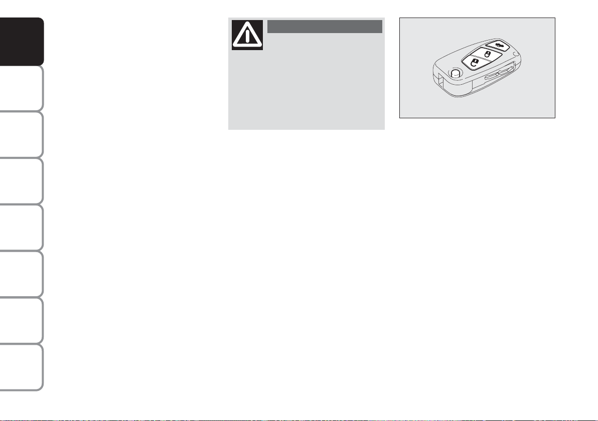
ELECTRICAL ACCESSORIES
If, after buying the car, you decide to add accessories that require electrical power supply
(that will gradually drain the battery), address the Lancia Dealership. They can calculate the overall
electrical absorption and check that the car electric system can support the required load.
CODE card
Keep it in a safe place, not in the car. We recommend that you should always carry the electronic code
provided on the CODE card with you, in case you need to perform an emergency start.
SCHEDULED SERVICING
Correct car maintenance is essential for ensuring that the car stays in tip-top condition and safeguards its
safety features, its environmental friendliness and low running costs for a long time to come.
THE OWNER’S MANUAL CONTAINS…
... important information, advise and warnings for correct use, driving safety and maintenance of your car
over time. Special attention must be paid to the symbols provided " (safety of persons) # (environmental
protection) â (car integrity).
If the multifunction display shows a message reading “See handbook”, you should refer to the section
“Warning lights and messages” in this handbook.
쇵
Page 8

DASHBOARD AND CONTROLS
DASHBOARD........................................................ 8
INSTRUMENT PANEL.......................................... 10
SYMBOLS ............................................................. 11
THE LANCIA CODE SYSTEM.............................. 11
THE KEY AND DOOR LOCKING KIT ................. 13
IGNITION DEVICE .............................................. 20
INSTRUMENTS ................................................... 21
MULTIFUNCTIONAL DISPLAY
(on two-line modal panel)...................................... 22
MULTIFUNCTIONAL DISPLAY
(on three-line modal panel).................................... 25
ADJUSTING THE SEATS ..................................... 38
HEAD RESTRAINTS ............................................ 44
ADJUSTING THE STEERING WHEEL ............... 45
REARVIEW MIRRORS.......................................... 46
HEATING/CLIMATE CONTROL SYSTEM .......... 47
MANUAL CLIMATE CONTROL SYSTEM ........... 48
AUTOMATIC CLIMATE CONTROL
SYSTEM (TWO-ZONE) ....................................... 52
EXTERNAL LIGHTS ........................................... 62
WINDOW WASHING ............................................ 64
CRUISE CONTROL ............................................. 67
CEILING LIGHTS................................................. 69
LIGHT CONTROL BUTTONS .............................. 71
FUEL CUT-OFF INERTIAL SWITCH................... 72
INTERNAL EQUIPMENT .................................... 73
SMOKERS KIT...................................................... 75
SUN VISORS......................................................... 76
SUNROOF ............................................................ 76
POWER WINDOWS ............................................. 78
BOOT .................................................................... 80
BONNET ............................................................... 82
ROOF BARS .......................................................... 83
HEADLIGHTS ...................................................... 84
ABS SYSTEM ....................................................... 85
EOBD SYSTEM .................................................... 86
SOUND SYSTEM .................................................. 87
ACCESSORIES PURCHASED BY THE OWNER .. 88
“DUALDRIVE” ELECTRIC POWER
STEERING SYSTEM ............................................ 89
PARKING SENSORS ............................................ 91
REFUELLING ...................................................... 92
ENVIRONMENTAL PROTECTION ..................... 94
DASHBOARD
AND CONTROLS
SAFETY
DEVICES
AND
DRIVING
STARTING
WARNING
MESSAGES
LIGHTS AND
IN AN
EMERGENCY
AND CARE
MAINTENANCE
TECHNICAL
SPECIFICATIONS
INDEX
7
Page 9
DASHBOARD
AND CONTROLS
SAFETY
DEVICES
AND
DRIVING
STARTING
WARNING
MESSAGES
LIGHTS AND
IN AN
EMERGENCY
AND CARE
MAINTENANCE
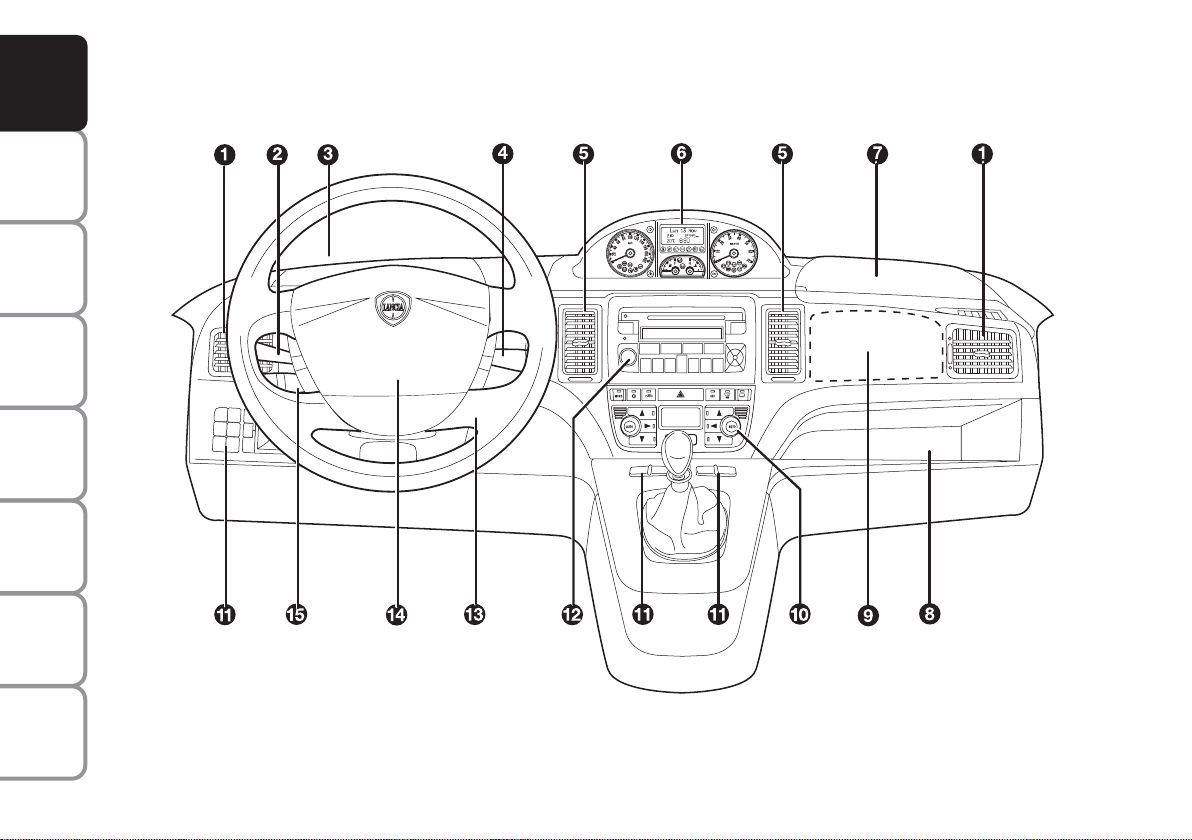
DASHBOARD
The presence and position of the controls, instruments and indicators may vary according to the different versions.
The upper and lower central panel offers several solutions according to the Customer’s requirements (see the illustrations
below).
SPECIFICATIONS
fig. 1
TECHNICAL
1. Side air vents - 2. Left stalk - 3. Upper left-hand glove box - 4. Right stalk - 5. Central air vents - 6. Instrument panel -
7. Upper right-hand glove box - 8. Glove box compartment - 9. Passenger’s airbag - 10. Controls for heating/ventilation/
INDEX
climate control - 11. Control buttons - 12. Sound system (where provided) - 13. Ignition converter - 14. Driver’s airbag -
15. Cruise control (where provided).
8
L0D0374m
Page 10
fig. 2
fig. 3
L0D0231m
L0D0232m
fig. 5
fig. 6
L0D0234m
L0D0235m
Upper central panel:
❒ with fixed glove box compartment,
A-fig. 2, and extractable compartment (DIN), B-fig. 2, for audio system installation;
❒ with required auto system, fig. 3;
❒ with Connet Nav+, fig. 4;
Lower central panel:
❒ with manual climate control system,
B-fig. 5;
❒ with automatic two-zone climate
control system, C-fig. 6.
DASHBOARD
AND CONTROLS
SAFETY
DEVICES
AND
DRIVING
STARTING
WARNING
MESSAGES
LIGHTS AND
IN AN
EMERGENCY
AND CARE
MAINTENANCE
fig. 4
L0D0359m
TECHNICAL
SPECIFICATIONS
INDEX
9
Page 11
INSTRUMENT PANEL
DASHBOARD
AND CONTROLS
SAFETY
DEVICES
AND
DRIVING
STARTING
WARNING
MESSAGES
LIGHTS AND
IN AN
EMERGENCY
AND CARE
MAINTENANCE
TECHNICAL
SPECIFICATIONS
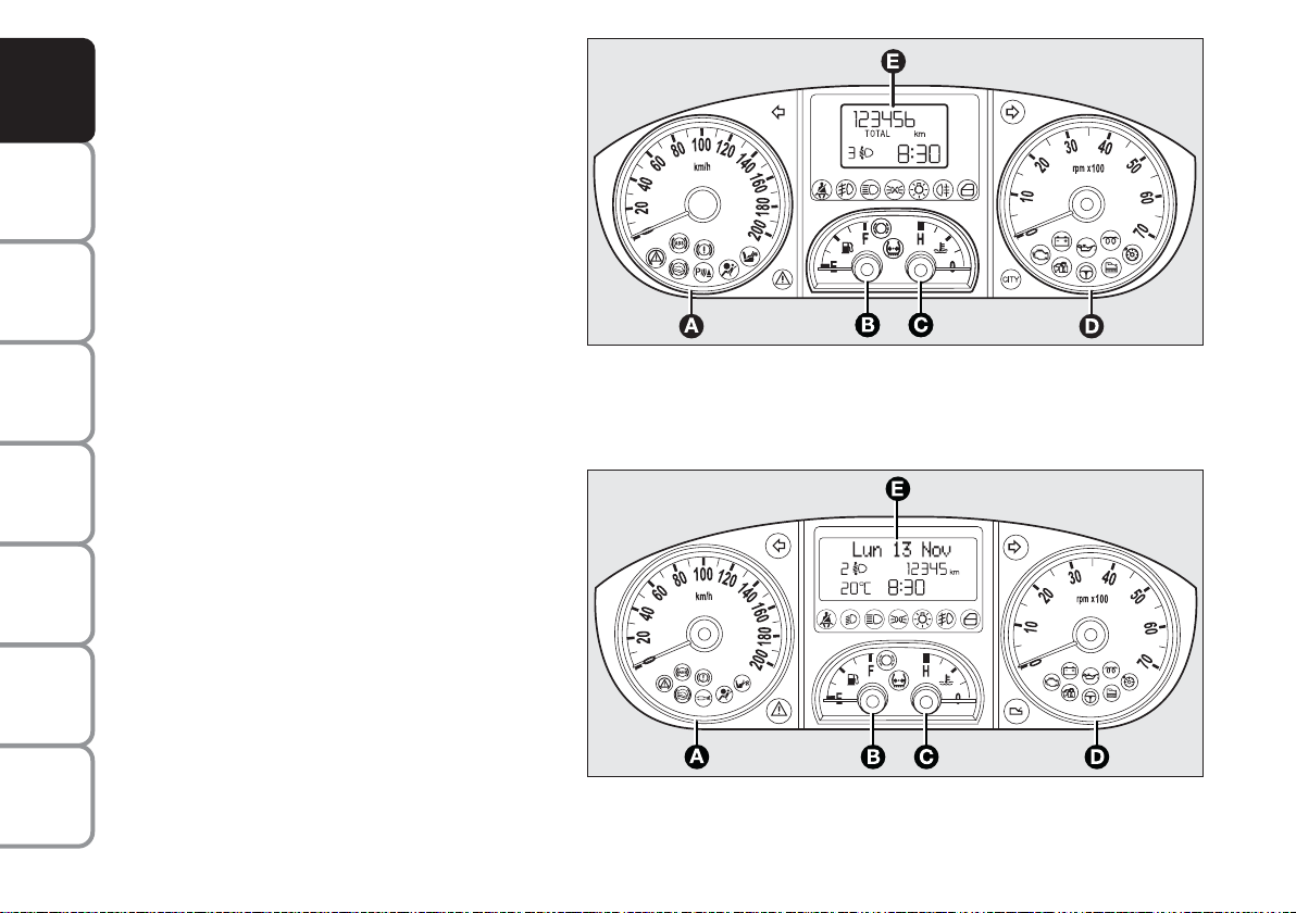
Modal panel
A - Speedometer (speed indicator)
B – Fuel level gauge with reserve warning light
C – Engine coolant temperature gauge and
excessive temperature warning light
D - Rev. counter
E - Multifunctional display
cm Warning lights installed on Multijet versions
only
Comfort
A - Speedometer (speed indicator)
B – Fuel level gauge with reserve warning light
C – Engine coolant temperature gauge and
excessive temperature warning light
D - Rev. counter
E - Reconfigurable multifunctional display
cm Warning lights installed on Multijet versions
only
fig. 7
L0D0372m
INDEX
10
fig. 8
L0D0010m
Page 12
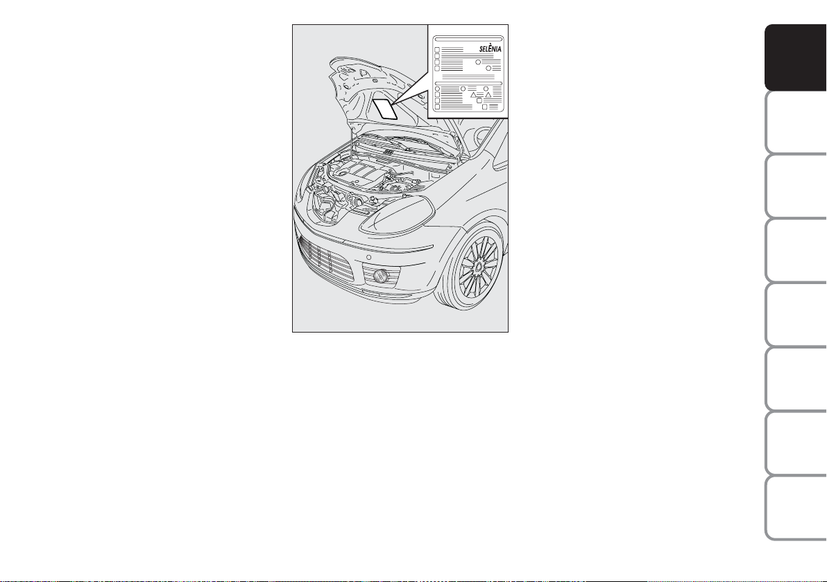
SYMBOLS
THE LANCIA CODE
Special coloured labels have been attached near or actually on some of the
components of your car. These labels
bear symbols that draw your warning
to the precautions required when handling the component in question.
The plate summarising the symbols
used can be found under the bonnet,
fig. 9.
fig. 9
L0D0375m
SYSTEM
This is an electrical engine locking
system which increases protection
against attempted theft of the car. It
is automatically activated when the
ignition key is extracted.
Each key contains an electronic device which modulates the signal emitted during ignition by an antenna
built in the ignition device. This signal is the ‘password’, which changes
at each ignition and is used by the
control unit to acknowledge the key
and allow ignition.
DASHBOARD
AND CONTROLS
SAFETY
DEVICES
AND
DRIVING
STARTING
WARNING
MESSAGES
LIGHTS AND
IN AN
EMERGENCY
AND CARE
MAINTENANCE
TECHNICAL
SPECIFICATIONS
INDEX
11
Page 13
DASHBOARD
AND CONTROLS
SAFETY
DEVICES
AND
DRIVING
STARTING
WARNING
MESSAGES
LIGHTS AND
IN AN
EMERGENCY
AND CARE
MAINTENANCE
OPERATION
Each time the car is started by turning the ignition key to MAR, the Lancia CODE system control unit sends
an acknowledgement code to the engine control unit to deactivate the inhibitor. The code is sent only if the
control unit of the Lancia CODE system has acknowledged the code received from the key. Each time the ignition key is turned to STOP, the
Lancia CODE system deactivates the
functions of the electronic engine control unit.
If, during ignition, the code is not correctly recognized, a warning light
is lit on the instrument panel.
Y
In this case, turn the key to STOP
and then back to MAR. Try with the
other keys provided if the problem
persists. If the engine will not start up
after this operation contact the
Lancia Dealership.
IMPORTANT Each key has its own
code which must be stored by the system ECU. Contact the Lancia Dealership to have new keys (up to max.
eight) with the code stored in them.
Warning light
coming on
Y
when driving
❒ If the warning light
the system is running a self-test
(such as following a voltage failure). If the problem persists, contact the Lancia Dealership.
The electronic components
inside the key may be damaged if the key is submitted
to sharp knocks.
Y
turns on,
TECHNICAL
SPECIFICATIONS
INDEX
12
Page 14
THE KEY AND
DOOR LOCKING
KIT
DASHBOARD
AND CONTROLS
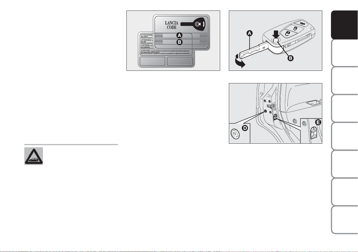
CODE CARD Fig. 10
The car is delivered with the ignition
key and the CODE card which bears
the following data:
❒ the mechanical key code B to be
given to the Lancia Dealership
when ordering duplicate keys.
IMPORTANT In order to ensure perfect efficiency of the electronic devices
inside the keys, they should never be
exposed to direct sunlight.
All the keys and the CODE
card must be handed over
to the new owner when selling the car.
fig. 10
L0D0376m
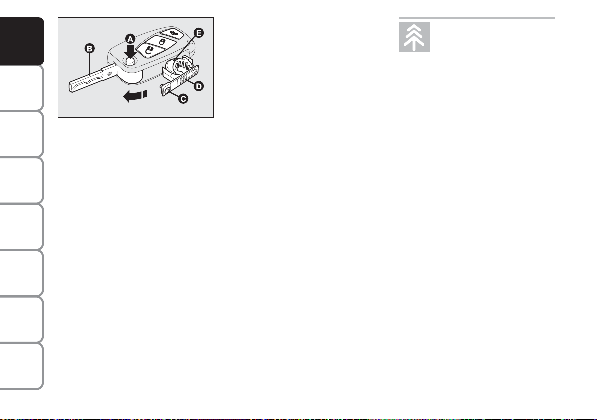
MAIN KEY WITH REMOTE
CONTROL fig. 11
The metal insert of the key A is recessed in the grip.
The key operates:
❒ the ignition switch;
❒ the lock of the door on the driver’s
side;
❒ the lock/release device of the fuel
flap (on versions equipped with a
lockable fuel plug)
fig. 11
fig. 12
L0D0377m
L0D0246m
❒ engagement of the device, D-fig.
12, for locking external opening of
the front and rear doors when the
electric system does not work (e.g.
the battery is down);
❒ engagement of the child safety
lock device, E-fig. 12, installed on
the rear doors.
Button B-fig. 11 enables opening of
the metal insert A.
SAFETY
DEVICES
AND
DRIVING
STARTING
WARNING
MESSAGES
LIGHTS AND
IN AN
EMERGENCY
AND CARE
MAINTENANCE
TECHNICAL
SPECIFICATIONS
INDEX
13
Page 15
DASHBOARD
AND CONTROLS
SAFETY
DEVICES
AND
DRIVING
STARTING
WARNING
MESSAGES
LIGHTS AND
IN AN
EMERGENCY
AND CARE
MAINTENANCE
TECHNICAL
SPECIFICATIONS
To refit metal insert A, proceed as
follows:
❒ Press button B and hold it pressed.
❒ move the metal insert A.
❒ Release button B and turn the
metal insert A until hearing the
click that indicates correct locking.
The button
Ëactivates the release de-
vice for doors, tailgate and fuel flap
(where provided).
The button Áactivates the release device for doors, tailgate and fuel flap
(where provided).
The button R activates opening of
the tailgate.
WARNING
Press button B-fig. 11 only
after moving the key away
from your body, especially your
eyes, and from objects which could
get damaged (e.g. your clothes). Do
not leave the key unattended, because someone, a child especially,
may accidentally press the button
while handling the key.
Door and tailgate lock release
Short pressure on button Ë: lock release of doors, tailgate and fuel flap,
timed switching on of the internal
ceiling lights and double flashing of
direction indicators.
Door locks are automatically released
in case of intervention of the inertial
fuel cut-off switch.
Use the “Setup Menu” of the multifunctional reconfigurable display (see
the dedicated paragraph in section
“Dashboard and Controls”) to set the
system in such a way that only the
door on the driver’s side is released
when pressing button Ë.
fig. 13
L0D0378m
IMPORTANT The remote control frequency may be disturbed by radio
transmissions outside the car (e.g. cellular phones, radio amateurs, etc.). If
this is the case, the remote control
may operate incorrectly.
Door and tailgate locking
Short pressure on button Á: remote
lock of doors, tailgate and fuel flap,
switching off of the internal ceiling
lights and single flashing of direction
indicators.
INDEX
14
Page 16
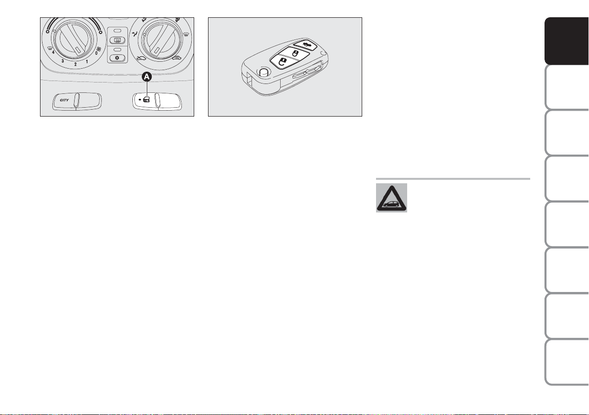
fig. 14
L0D0417m
Deterrence led indications
When locking the doors, the deterrence LED A-fig. 14 on the button
switches on for about 3 seconds.
Then, it starts flashing (deterrence
function). If one or more than one
door or the tailgate does not close correctly when locking it, the LED and
direction indicators start flashing
quickly.
IMPORTANT The remote control frequency may be disturbed by radio
transmissions outside the car (e.g. cellular phones, radio amateurs, etc.). If
this is the case, the remote control
may operate incorrectly.
fig. 15
Remote tailgate opening
L0D0378m
fig. 15
Press the button R , and hold it
pressed, to release (open) the tailgate
remotely. Tailgate opening is indicated
by double flashing of the direction indicators; tailgate closing by single
flashing.
IMPORTANT The remote control frequency may be disturbed by radio
transmissions outside the car (e.g. cellular phones, radio amateurs, etc.). If
this is the case, the remote control
may operate incorrectly.
Door locking from the inside
Keep the doors locked and press the
button A-fig. 14 positioned at the
centre of the dashboard to either lock
or release the doors.
IMPORTANT If one door is not correctly locked, or a system fault occurs,
doors cannot be locked from the inside.
After eliminating the cause of the
problem, the device resumes regular
operation.
If the button for locking
doors from the inside is accidentally pressed, only the
doors opened for getting out
of the car are released; the tailgate
remains locked. For system reset
press the lock/release buttons again.
DASHBOARD
AND CONTROLS
SAFETY
DEVICES
AND
DRIVING
STARTING
WARNING
MESSAGES
LIGHTS AND
IN AN
EMERGENCY
AND CARE
MAINTENANCE
TECHNICAL
SPECIFICATIONS
INDEX
15
Page 17
DASHBOARD
AND CONTROLS
SAFETY
DEVICES
AND
DRIVING
STARTING
WARNING
MESSAGES
LIGHTS AND
IN AN
EMERGENCY
AND CARE
MAINTENANCE
fig. 16
L0D0379m
Replacing the battery of the key
with remote control fig. 16
Battery replacement:
❒ press button A and bring the metal
insert B to the “open” position;
❒ turn the screw C using a fine bit
screwdriver;
❒ take out the battery case D and re-
place the battery E respecting its
polarity;
❒ fit the battery case D back inside
the key and lock it turning screw
C.
Request for additional remote
controls
The system acknowledges up to 8 remote controls. Should a new remote
control be necessary, contact a Lancia
Dealership and be ready to present
the CODE card, a personal identity
document and the car’s ownership
documents.
Used batteries are harmful
to the environment. They
should be disposed of as
specified by law in special
containers or taken to a Lancia
Dealership, which will take care of
their disposal.
TECHNICAL
SPECIFICATIONS
INDEX
16
Page 18
(SPARE) MECHANICAL
KEY, fig. 17-18
Depending on the version, the car is
either supplied with a recessed key 1
or fixed key 2.
The metal insert A of the key 1 is recessed in the grip.
The button B activates opening of the
metal insert A.
The metal insert A is placed back in
the grip as follows.
❒ Press button B and hold it pressed.
❒ Move the metal insert A.
❒ Release button B and turn the
metal insert A until hearing the
click that indicates correct locking.
fig. 17
L0D0014m
WARNING
Only press button B with
the key away from your
body, specifically from your eyes
and from objects which could get
damaged (e.g. your clothes). Do not
leave the key unattended, because
someone, a child especially, may
accidentally press the button while
handling the key.
fig. 18
L0D0380m
The keys are used to activate:
❒ the ignition switch;
❒ the lock of the door on the driver’s
side;
❒ the fuel flap lock/release (on ver-
sions supplied with a lockable
plug)
❒ engagement of the child safety
lock device when the electric system does not work (e.g. when the
battery is down);
❒ engagement of the child safety
lock device on the rear doors.
DASHBOARD
AND CONTROLS
SAFETY
DEVICES
AND
DRIVING
STARTING
WARNING
MESSAGES
LIGHTS AND
IN AN
EMERGENCY
AND CARE
MAINTENANCE
TECHNICAL
SPECIFICATIONS
INDEX
17
Page 19

The main functions that can be activated with the keys (with or without remote control) are the following:
DASHBOARD
AND CONTROLS
SAFETY
DEVICES
AND
DRIVING
STARTING
WARNING
MESSAGES
LIGHTS AND
IN AN
EMERGENCY
AND CARE
MAINTENANCE
TECHNICAL
SPECIFICATIONS
Type of key
Spare
mechanical
key
Door lock release
Turn the key
anticlockwise
(driver’s side)
Turn the key
anticlockwise
(driver’s side)
Main key
with remote control
Short pressing
of button Ë
blinks twice
Direction indicators flashing
(only when key
has remote control)
Deterrence led
Switching off
Pressing button Ë activates opening of the fuel flap.
Door locking
from the outside
Turn the key
clockwise
(driver’s side)
Turn the key
clockwise
(driver’s side)
Short pressing of
button Á
blinks once
Steady for
approximately 3 seconds
and then
deterrent blinking
Unlocking the
tailgate
Prolonged button pressing
(for over 2 seconds) R
blinks twice
Deterrence led
INDEX
18
Page 20
WARNING
Engagement of the child
lock system A-fig. 19 is
ensured exclusively if the revolving plug is rotated until the correct
horizontal position (1) is reached.
DASHBOARD
AND CONTROLS
SAFETY
DEVICES
fig. 19
L0D0101m
CHILD LOCK SYSTEM fig. 19
This device prevents opening of the
rear doors from the inside.
This device can be engaged only with
rear doors open.
❒ position 1 - engaged (door locked);
❒ position 2 - disengaged (door can
be opened from the inside).
The device A stays on even if the
doors are unlocked by the centralised
system.
IMPORTANT Always use this device
when transporting children.
IMPORTANT After engaging the
child lock on both rear doors, check
for proper engagement by trying to
open a rear door with the internal
handle.
WARNING
Disengagement of the child
lock system A-fig. 19 is
ensured exclusively if the revolving plug is rotated until the correct
vertical position (2) is reached.
EMERGENCY DEVICE FOR
EXTERNAL DOOR LOCKING
fig. 20
The doors are fitted with an emergency device to lock them when there
is no power.
In this case, the car doors are locked
as follows.
❒ Fit the ignition key into the re-
volving plug B.
❒ Turn the device to position 1 and
close the door.
fig. 20
L0D0247
The doors are opened as follows.
❒ Fit the key into the revolving plug
of the door lock on the driver’s
side and turn it anticlockwise.
❒ Open the door on the driver’s side.
❒ Sit in the car and open the re-
maining doors using the stalks of
the opening handles.
WARNING
Do not engage the child
lock system simultane-
ously with the door opening stalk.
AND
DRIVING
STARTING
WARNING
MESSAGES
LIGHTS AND
IN AN
EMERGENCY
AND CARE
MAINTENANCE
TECHNICAL
SPECIFICATIONS
INDEX
19
Page 21
DASHBOARD
AND CONTROLS
SAFETY
DEVICES
AND
DRIVING
STARTING
WARNING
MESSAGES
LIGHTS AND
IN AN
EMERGENCY
AND CARE
MAINTENANCE
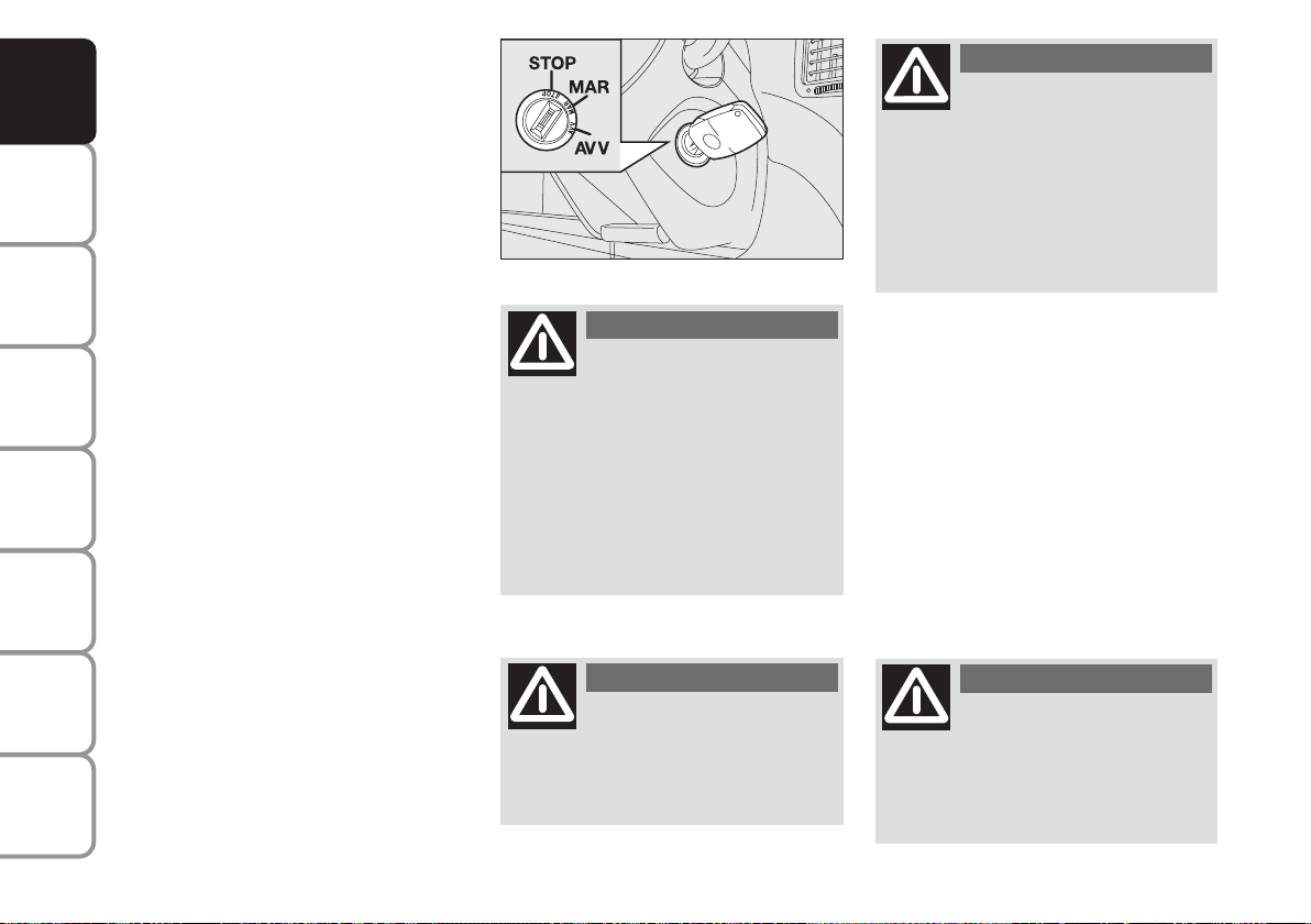
IGNITION DEVICE
The key can be turned to 3 different
positions:
❒ STOP: engine off, key extractable,
steering locked. Some electrical
devices (e.g. sound system, power
windows, etc.) work regularly.
❒ MAR: driving position. All electri-
cal devices work regularly.
❒ AV V: engine starting (unstable po-
sition).
The ignition switch is fitted with an
electronic safety system that turns the
ignition key back to position STOP if
the engine will not start, before repeating the starting operation.
fig. 21
L0D0021m
WARNING
Under no circumstances
should aftermarket works
be carried out, because they may
cause tampering with the driving
system or steering column (e.g. installation of anti-theft device),
which may lead to reduced system
performances and loss of the warranty as well as safety-specific
problems and non-compliance
with the car type-approval.
WARNING
Always remove the key
from the car when leaving
it in order to prevent accidental engagement of the controls. Remember to engage the handbrake. Engage first gear if the car is parked
uphill or reverse if the car is
parked downhill. Never leave children unattended in the car.
STEERING COLUMN LOCK
Engagement
When the key is in position STOP, remove the key and turn the steering
wheel until it is locked.
Disengagement
Rock the steering wheel slightly as you
turn the ignition key to MAR.
TECHNICAL
SPECIFICATIONS
INDEX
20
WARNING
If the ignition system is
tampered with (e.g. after
an attempted theft), address a
Lancia Dealership to have the system checked before starting off.
WARNING
Never extract the key while
the car is moving. The
steering wheel would be locked as
soon as the steering wheel is turned.
This also applies to cases in which
the car is towed.
Page 22
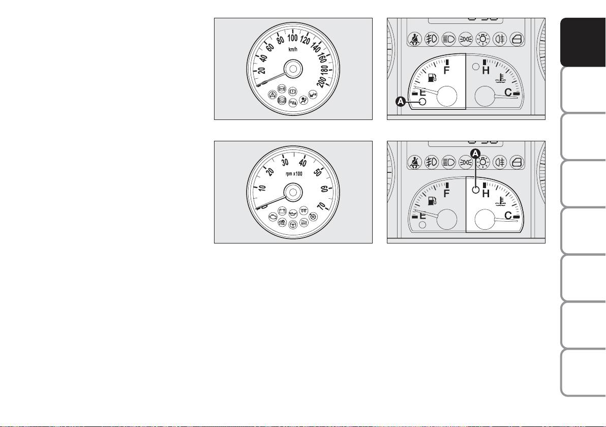
INSTRUMENTS
SPEEDOMETER fig. 22
It shows the car speed.
REV. COUNTER fig. 23
It shows the engine revolutions per
minute.
IMPORTANT The electronic injection
control system gradually shuts off the
flow of fuel when the engine is “overrevving”, thus causing a gradual loss
of engine power.
When the engine is idling, the rev
counter may indicate a gradual or
sudden increase of the speed.
This is normal and does not indicate
a fault. It may be caused, for example, by the operation of the climate
control system or fan. In these cases,
a slow change in engine speed is used
to protect the battery charge.
fig. 22
fig. 23
L0D0241m
L0D0242m
FUEL LEVEL GAUGE fig. 24
This gauge gives an indication of the
litres of fuel in the tank (see the information provided in paragraph “Refuelling the car”).
fig. 24
fig. 25
L0D0023m
L0D0024m
The reserve warning light A turns on
to indicate that approximately
6 litres of fuel are left in the tank.
Do not travel with the tank nearly
empty: lack of fuel supply could damage the catalyser.
DASHBOARD
AND CONTROLS
SAFETY
DEVICES
AND
DRIVING
STARTING
WARNING
MESSAGES
LIGHTS AND
IN AN
EMERGENCY
AND CARE
MAINTENANCE
TECHNICAL
SPECIFICATIONS
21
INDEX
Page 23
DASHBOARD
AND CONTROLS
SAFETY
DEVICES
AND
DRIVING
STARTING
WARNING
MESSAGES
LIGHTS AND
IN AN
EMERGENCY
AND CARE
MAINTENANCE
TECHNICAL
SPECIFICATIONS
ENGINE COOLANT
TEMPERATURE GAUGE fig. 25
Warning light A turns on to indicate
that the temperature of the engine
coolant has remarkably increased. In
this case, stop the engine and go to a
Lancia Dealership. This shows the temperature of the engine coolant fluid and
starts working when the fluid temperature exceeds approx. 50°C. In regular
operating conditions the needle moves
to the different positions allowed inside
the gauge according to the car operating conditions and management of the
engine cooling system.
IMPORTANT If the needle gets positioned at the beginning of the scale
(temperature low) and the warning
light A is on, a failure has occurred in
the system. If this is the case, go to a
Lancia Dealership to have the system
checked.
If the needle indicating the
engine coolant temperature
reaches the red area, stop
the engine immediately and
contact a Lancia Dealership.
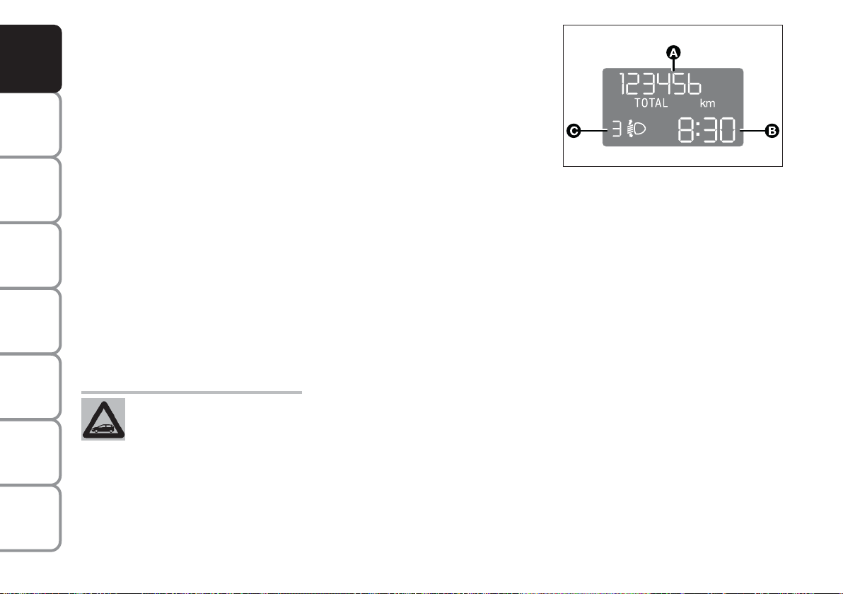
MULTIFUNCTIONAL
DISPLAY
(on two-line modal
panel)
The car can be equipped with a multifunction display that shows useful information for car driving according to
the settings made.
fig. 26
L0D0027m
“STANDARD” SCREEN fig. 26
The standard screen shows the following information:
A Odometer (viewing of covered km
or miles)
B Time (always displayed, even with
ignition key removed and front
doors closed)
C Headlight aiming position (only
with dipped beam headlights on).
NOTE When opening one of the front
doors, the display turns on and shows
the clock and the kilometres or miles
covered for a few seconds.
INDEX
22
Page 24
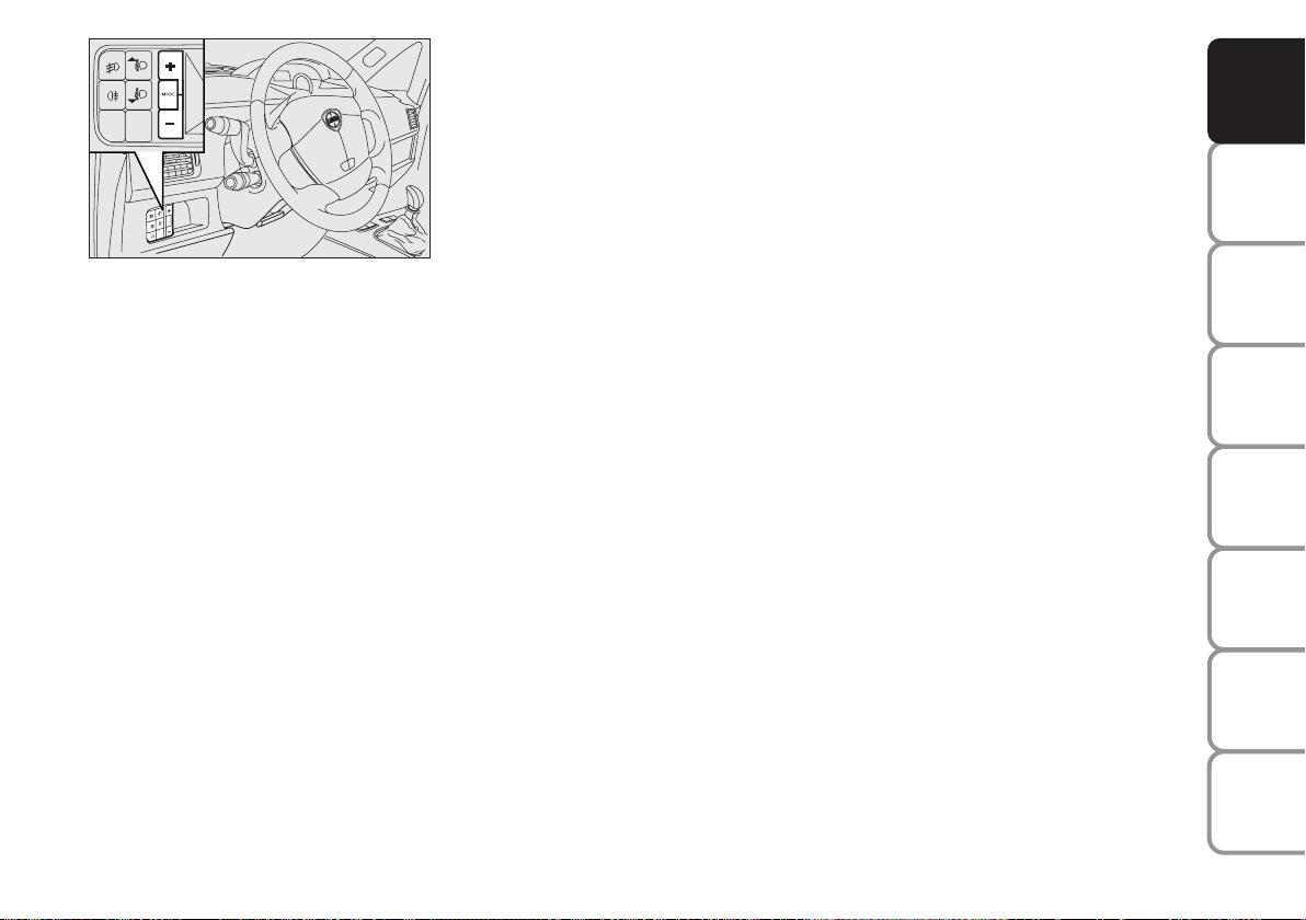
fig. 27
L0D0384m
CONTROL BUTTONS fig. 27
+ To scroll the next items on the dis-
played menu and the related options or increase the displayed
value.
MODE Press briefly to access the
menu and/or go to next
screen or confirm the required menu option.
Hold pressed to go back to
the standard screen.
– To scroll the previous items on the
displayed menu and the related
options or reduce the displayed
value.
NOTE Buttons + and – activate different functions according to the following situations.
SETUP MENU
The “Setup Menu” is used to make
the following settings and/or adjustments:
❒ ADJUSTING THE CLOCK
❒ ADJUSTING THE BUZZER
VOLUME
❒ SETTING THE SPEED LIMIT
❒ SETTING THE UNIT
Adjusting the clock
The car is delivered with the clock adjusted for 24 hours.
To set the required time proceed as
follows:
❒ press the button MODE several
times until the text “Hour” appears;
❒ press the button + to increase the
time by one minute;
❒ press the button – to reduce the
time by one minute;
Hold the buttons + or – pressed for a
few seconds to automatically start
quick increase or reduction of the
time until the buttons are released.
❒ Press the button MODE and hold
it pressed for over 2 seconds to
confirm the time change.
Adjusting the buzzer volume
To adjust the desired volume proceed
as follows:
❒ press the button MODE several
times until the text “bUZZ” appears;
❒ press the button + to increase the
volume;
❒ press the button – to reduce the
volume;
❒ press the button MODE and hold
it pressed for over 2 seconds to
confirm the volume change.
Indication that the set peed limit
has been exceeded
Proceed as described below to set a
reference car speed value beyond
which the system warns the driver
about this by displaying a message
and starting the buzzer.
The car is delivered with this function
in “OFF”mode.
DASHBOARD
AND CONTROLS
SAFETY
DEVICES
AND
DRIVING
STARTING
WARNING
MESSAGES
LIGHTS AND
IN AN
EMERGENCY
AND CARE
MAINTENANCE
TECHNICAL
SPECIFICATIONS
INDEX
23
Page 25
DASHBOARD
AND CONTROLS
SAFETY
DEVICES
AND
DRIVING
STARTING
WARNING
MESSAGES
LIGHTS AND
IN AN
EMERGENCY
AND CARE
MAINTENANCE
Set this function as follows:
❒ press the button MODE several
times until the text “SPEED” appears;
❒ press the button + to increase the
speed value (max. limit being 250
Km/h);
❒ press the button – to reduce the
speed value (min. limit being 30
Km/h below which the system
goes back to “OFF” mode);
❒ press the button MODE and hold
it pressed for over 2 seconds to
confirm the speed setting.
Setting the unit
To set the required unit (kilometres or
miles) proceed as follows:
❒ press the button MODE several
times until the text “Unit” appears;
❒ press the button + or – to change
the unit;
❒ press the button MODE and hold
it pressed for over 2 seconds to
confirm the unit setting.
Viewing of the
fuel cut-off inertial switch
tripping
The screen automatically appears
whenever the fuel cut-off inertial
switch trips after a significant collision.
This switch stops fuel supply.
See the information provided in the
dedicated chapter “Fuel cut-off inertial switch”.
WARNING
If, after the message
“FPSon” appears, you
smell fuel or see leaks from the fuel
supply system, do not reset the
switch to avoid the risk of starting
a fire.
TECHNICAL
SPECIFICATIONS
INDEX
24
Page 26
MULTIFUNCTIONAL
DISPLAY
(on three-line
comfort panel)
The car can be equipped with a multifunction display that shows useful
information for car driving according
to the settings made.
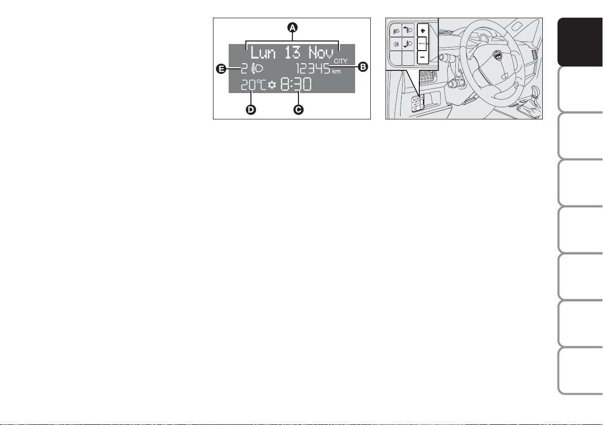
“STANDARD” SCREEN fig. 29
The standard screen shows the following information:
A Date
B Odometer (viewing of covered km
or miles)
C Time (always displayed, even with
ignition key removed and front
doors closed)
fig. 29
L0D09000m
D External temperature
E Headlight aiming position (only
with dipped beam headlights on)
NOTE When opening one of the front
doors, the display turns on and shows
the clock and the kilometres or miles
covered for a few seconds.
fig. 30
L0C0384m
CONTROL BUTTONS fig. 30
+ To scroll the next items on the dis-
played menu and the related options or increase the displayed
value.
MODE Press briefly to access the
menu and/or go to next
screen or confirm the required menu option.
Hold pressed to go back to
the standard screen.
– To scroll the previous items on the
displayed menu and the related
options or reduce the displayed
value.
NOTE Buttons
ferent functions according to the following situations.
+ and – activate dif-
DASHBOARD
AND CONTROLS
SAFETY
DEVICES
AND
DRIVING
STARTING
WARNING
MESSAGES
LIGHTS AND
IN AN
EMERGENCY
AND CARE
MAINTENANCE
TECHNICAL
SPECIFICATIONS
25
INDEX
Page 27

DASHBOARD
AND CONTROLS
SAFETY
DEVICES
AND
DRIVING
STARTING
WARNING
MESSAGES
LIGHTS AND
IN AN
EMERGENCY
AND CARE
MAINTENANCE
TECHNICAL
SPECIFICATIONS
Adjustment of
headlight aiming device (only with
dipped beam headlights on)
- when the standard screen is enabled,
the headlight aiming device can be
regulated (refer to paragraph “Headlights” in this section).
Setup menu
- to scroll the previous and next items
in the menu;
- to increase or decrease values during setting operations.
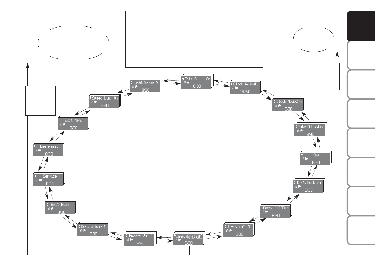
SETUP MENU fig. 31
The menu comprises a series of functions arranged in a cycle which can be
selected through buttons
+ and – to
access the different “select” operations and settings (setup) described in
the following paragraphs.
The setup menu is activated by pressing briefly button MODE.
Intermittent pressing of buttons
+ and
– enables scrolling of the setup menu
options.
Handling modes are different according to the characteristic of the option
selected.
NOTE If the Connect Nav+ system is
installed, only the following functions
can be adjusted/set from the Instrument Panel: “Brightness”, “Speed
Beep”, Light Sensors” (where provided), “Seat belt Buzzer” and “Passenger’s Airbag”. The other functions
are displayed on the Connect Nav+
system which is used to adjust/set
them.
Selecting a menu option
– Briefly press button MODE to select
the menu option that needs to be
changed.
– Press buttons
+ and – (by single
pressing) to select the new setting.
– Briefly press button MODE to store
the new setting and at the same time
go back to the previously selected
menu option.
Selecting the “Set Date”
and “Set time”
– Briefly press button MODE to select
the first value to be changed (e.g.
hours /minutes or year / month /
day).
– Press buttons + and – (by single
pressing) to select the new setting.
– Briefly press button MODE to store
the new setting and at the same time
go to the next setup menu option. If
the processed option is the last one,
the system brings you back to the previously selected option of the main
menu.
Prolonged pressing of the
button MODE enables:
– exiting the setup menu page and
saving of the changes already stored
by the driver (and confirmed by
briefly pressing the button MODE).
The setup menu page is timed. Only
the changes saved by the user by
briefly pressing MODE are saved
when the menu is automatically
closed.
INDEX
26
Page 28
Example:
Italiano
Português
MODE
brief button
pressing
+
+
–
+
fig. 31
Deutsch
Français
–
BAG. PASS.
SERVICE
–
BELT BUZZ.
(*) where provided
–
+
English
Español
+
+
–
SPEED BEEP.
EXITING THE MENU
VOL. BUTTONS
VOL. BUZZER
–
+
From the standard screen, briefly press button MODE
to start browsing. Press + or – to browse within the
menu. NOTE Only the short menu may be accessed for
reasons of safety while the car is moving (“Brightness”
and “Speed Beep” settings). Stop the car to access the
full menu. In cars equipped with a Connect Nav+ system, many functions are viewed from the navigator display.
+
–
CLOCK SETTING
CLOCK MODE
CONSUMPTION
–
+
LIGHT SENS.
–
+
–
LANGUAGE
–
+
TRIP B
TEMP. UNIT
Example:
Year Month
+
–
–
SETTING THE DATE
KEY
DIST. UNIT
–
–
+
(*) This function may only
be displayed after the SBR
system is deactivated by a
Lancia Dealership.
Day
MODE
brief button
pressing
–
–
+
DASHBOARD
AND CONTROLS
SAFETY
DEVICES
AND
DRIVING
STARTING
+
WARNING
MESSAGES
LIGHTS AND
+
IN AN
EMERGENCY
+
AND CARE
MAINTENANCE
TECHNICAL
SPECIFICATIONS
INDEX
27
Page 29

DASHBOARD
AND CONTROLS
SAFETY
DEVICES
AND
DRIVING
STARTING
WARNING
MESSAGES
LIGHTS AND
IN AN
EMERGENCY
AND CARE
MAINTENANCE
Speed limit (Speed beep)
This function enables setting of the
car speed limit (km/h or mph). When
this limit is exceeded the driver is immediately alerted (see section “Warning lights and messages”).
To set the speed limit, proceed as follows:
– briefly press button MODE: the display will show the wording “Speed
Beep”;
– press button + or – to select speed
limit activation (On) or deactivation
(Off);
– if the function is on, press buttons +
or – to select the required speed limit
and then press MODE to confirm.
NOTE The speed may be set in the
range from 30 to 250 km/h, or from
20 to 155 mph according to the previously chosen unit (see “Setting the
distance unit”) described below. The
setting will increase/decrease by 5
units each time button + / – is pressed.
Hold button +/– pressed to increase/decrease the setting rapidly.
Complete the setting by briefly pressing the button when you approach the
required value.
– briefly press button MODE to go
back to the menu screen or press the
button for a prolonged time to go back
to the standard screen without storing
the settings.
To cancel the setting, proceed as follows:
– briefly press button MODE: ON
flashes on the display;
– press button +: OFF flashes on the
display;
– briefly press button MODE to go
back to the menu screen or press the
button for a prolonged time to go back
to the standard screen without storing
the settings.
TECHNICAL
SPECIFICATIONS
INDEX
28
Page 30

Adjusting the sensitivity of the
automatic headlight sensor
(Light sensor) (where provided)
This function is used to adjust the
dusk sensor sensitivity according to
three levels (level 1 = minimum, level
2 = medium, level 3 = maximum); the
higher the sensitivity, the lower the
quantity of external light needed to
switch the headlights on. The car is
delivered with this function set to level
“2”.
To change this setting:
– briefly press button MODE: the previously set level flashes on the display;
– press button + or – for selecting the
desired level;
– briefly press button MODE to go
back to the menu screen or press the
button for a prolonged time to go back
to the standard screen without storing
the settings.
Trip B On/Off (Trip B)
Through this option it is possible to
activate (On) or deactivate (Off) the
Trip B (partial trip) display.
For further information see section
“Trip computer”.
For activation / deactivation, proceed
as follows:
– briefly press button MODE: ON or
OFF flashes on the display (according
to previous setting);
– press button + or – for selecting the
desired value;
– briefly press button MODE to go
back to the menu screen or press the
button for a prolonged time to go back
to the standard screen without storing
the settings.
Setting the clock (Set time)
This function enables setting of the
clock.
To set the clock proceed as follows:
– briefly press button MODE: the display shows the “hours” flashing;
– press button + or – to set the clock;
– briefly press button MODE: “minutes”starts flashing on the display;
– press button + or – to set the clock.
NOTE The setting increases or decreases by one unit each time button
+ or – is pressed. Hold the button
pressed to automatically start a quick
increase/decrease of the set value.
Complete the setting by briefly pressing the button when the required setting is approached.
– briefly press button MODE to go
back to the menu screen or press the
button for a prolonged time to go
back to the standard screen without
storing the settings.
DASHBOARD
AND CONTROLS
SAFETY
DEVICES
AND
DRIVING
STARTING
WARNING
MESSAGES
LIGHTS AND
IN AN
EMERGENCY
AND CARE
MAINTENANCE
TECHNICAL
SPECIFICATIONS
INDEX
29
Page 31

DASHBOARD
AND CONTROLS
SAFETY
DEVICES
AND
DRIVING
STARTING
WARNING
MESSAGES
LIGHTS AND
IN AN
EMERGENCY
AND CARE
MAINTENANCE
12h/24h clock mode
(Clock mode)
This function enables setting the
screen to either 12 or 24 hour mode.
Proceed as follows:
– briefly press button MODE: 12h or
24h starts flashing on the display (depending on the previously set parameter);
– press button + or – for selecting the
desired value;
– briefly press button MODE to go
back to the menu screen or press the
button for a prolonged time to go back
to the standard screen without storing
the settings.
Setting the date (Set Date)
This function enables updating the
date (year - month - day).
To update the date proceed as follows:
– briefly press button MODE: the
year starts flashing on the display;
– briefly press button + or – to set the
year;
– briefly press button MODE: the
month starts flashing on the display;
– press button + or – to set the month;
– briefly press button MODE: the day
starts flashing on the display;
– press button + or – to set the day.
NOTE The setting increases or decreases by one unit each time button
+ or – is pressed. Hold the button
pressed to start automatic quick increase/ decrease of the setting. Complete the setting by briefly pressing
the button when the required setting
is approached.
– briefly press button MODE to go
back to the menu screen or press the
button for a prolonged time to go back
to the standard screen without storing
the settings.
Release of doors and tailgate (Key)
This function enables the release of
the front and rear doors, the release
of the driver's door only or the release
of all the doors including the tailgate.
To set the function, proceed as follows:
– press the MODE button for a short
time, the display shows “Open doors”,
“Op. drv.door” and “Open all”.
– press + or – to select; the selected
item will flash.
– Press MODE for a short time to return to the menu screen or press the
button for a longer time to return to
the standard screen without confirming the selection.
TECHNICAL
SPECIFICATIONS
INDEX
30
Page 32

Unit - “distance” (Dist. unit)
With this function it is possible to set
the units for distance covered (km or
mi).
To set the required unit proceed as
follows:
– briefly press button MODE: km or
mi will flash on the display (according to previous setting);
– press button + or – for setting;
– briefly press button MODE to go
back to the menu screen or press the
button for long to go back to the standard screen without storing settings.
Setting the consumption unit
(Consumption)
This function enables setting the unit
for the amount of fuel consumed
(km/l, l/100 or mpg) depending on
the distance unit selected (either km
or miles - see previous paragraph
“Distance Unit”).
If the distance unit set is “km”, the
display enables setting of the fuel consumption unit (km/l or l/100) depending on the amount of fuel consumed. If the distance unit set is “mi”,
the display shows the fuel consumption unit in “mpg”.
Set this value as follows:
– briefly press button MODE: either
km/l or l/100 starts flashing on the
display (depending on the previously
set parameter);
– press button + or – for selecting the
desired value;
– briefly press button MODE to go
back to the menu screen or press the
button for a prolonged time to go
back to the standard screen without
storing the settings.
DASHBOARD
AND CONTROLS
SAFETY
DEVICES
AND
DRIVING
STARTING
WARNING
MESSAGES
LIGHTS AND
IN AN
EMERGENCY
AND CARE
MAINTENANCE
TECHNICAL
SPECIFICATIONS
INDEX
31
Page 33

DASHBOARD
AND CONTROLS
SAFETY
DEVICES
AND
DRIVING
STARTING
WARNING
MESSAGES
LIGHTS AND
IN AN
EMERGENCY
AND CARE
MAINTENANCE
Setting the temperature unit
(Temp. unit)
This function enables setting of the required temperature unit (either °C or
°F).
To set the required unit proceed as
follows:
– briefly press button MODE: either
°C or °F starts flashing on the display
(depending on the previously set parameter);
– press button + or – for selecting the
desired value;
– briefly press button MODE to go
back to the menu screen or press the
button for a prolonged time to go
back to the standard screen without
storing the settings.
Selecting the language
(Language)
The messages can be displayed in the
following languages: Italian, German,
English, Spanish, French, Portuguese.
To set the required language proceed
as follows:
– briefly press button MODE: the previously set “language” starts flashing
on the display;
– press button + or – for selecting the
desired language;
– briefly press button MODE to go
back to the menu screen or press the
button for a prolonged time to go back
to the standard screen without storing
the settings.
Adjusting the failure/warning
buzzer volume (Buzzer Volume)
With this function the volume of the
buzzer accompanying any
failure/warning indication can be adjusted according to 8 levels. To adjust
the desired volume proceed as follows:
– briefly press button MODE: the previously set volume “level” starts flashing on the display;
– press button + or – for selecting the
desired volume level;
– briefly press button MODE to go
back to the menu screen or press the
button for a prolonged time to go back
to the standard screen without storing
the settings.
TECHNICAL
SPECIFICATIONS
INDEX
32
Page 34

Adjusting the button volume
(Button Vol.)
This function enables setting the volume of the roger-beep accompanying
the activation of buttons MODE, +
and – according to 8 levels.
To adjust the desired volume proceed
as follows:
– briefly press button MODE: the previously set volume “level” starts flashing on the display;
– press button + or – to set the volume
level;
– briefly press button MODE to go
back to the menu screen or press the
button for a prolonged time to go
back to the standard screen without
storing the settings.
S.B.R. buzzer reactivation
(Belt Buzzer) (where provided)
This function can only be displayed
after Lancia Dealership has deactivated the S.B.R. system (see paragraph “S.B.R. system” in section
“Safety devices”).
Scheduled Servicing (Service)
This function enables viewing of information on proper car servicing depending on the kilometres travelled or
daily intervals.
This information is consulted as follows:
– briefly press button MODE: the display shows service requirements in
km or mi according to the previous
setting (see paragraph “Distance
unit”);
– press button + or – to view the service interval in days;
– briefly press button MODE to go
back to the menu screen or press the
button for a prolonged time to go back
to the standard screen.
NOTE According to the “Scheduled
Servicing Plan” the car must be serviced every 20,000 km (or equivalent
mileage) or on a yearly basis. This
message appears automatically when
the key is positioned on MAR after
travelling for 2,000 km (or equivalent
mileage) or 30 days after the deadline. It appears every 200 km (or
equivalent mileage) or 3 days.
The indications will appear more frequently when there are 200 km left.
For 1.3 Multijet versions refer to the
instructions provided in the “Scheduled Servicing Plan” in section “Car
Maintenance” for air filter, engine oil
and engine oil filter replacement. The
indication will appear in kilometres or
miles according to the unit settings.
When the next scheduled servicing is
near, the message “Service” will appear on the display followed by the
number of kilometres or miles or days
left before servicing when the key is
turned to MAR. The “Scheduled Servicing” message shows information in
either kilometres (km) or miles (mi)
or in days (dd) depending on the
deadline showing up first. Go to the
Lancia Dealership where the servicing operations envisaged in the
“Scheduled Service Plan” or “Yearly
Inspection Plan” will be performed
and the message will be reset.
DASHBOARD
AND CONTROLS
SAFETY
DEVICES
AND
DRIVING
STARTING
WARNING
MESSAGES
LIGHTS AND
IN AN
EMERGENCY
AND CARE
MAINTENANCE
TECHNICAL
SPECIFICATIONS
INDEX
33
Page 35

DASHBOARD
AND CONTROLS
SAFETY
DEVICES
AND
DRIVING
STARTING
WARNING
MESSAGES
LIGHTS AND
IN AN
EMERGENCY
AND CARE
MAINTENANCE
Passenger front and side airbag
activation/deactivation
(where provided) (Passenger bag)
This function is used to activate/deactivate the front passenger’s airbag.
Proceed as follows:
❒ press button MODE: the display
shows messages “Bag pass: Off” (to
deactivate) or “Bag pass: On” (to
activate). Press the buttons + and –
followed by button MODE again;
❒ the confirmation request message
will be displayed;
❒ press buttons + or – to select either
Yes (to confirm activation/deactivation) or No (to abort);
❒ briefly press button MODE: the
display shows a message confirming the selected value. Now, go
back to the menu screen or press
the button for a prolonged time to
go back to the standard screen
without storing the settings.
L0D2170g
L0D2172g
L0D2174g
MODE
+
–
MODE
+
–
MODE
L0D2169g
+
–
L0D2171g
+
–
L0D2173g
L0D2174g
TECHNICAL
SPECIFICATIONS
INDEX
34
L0D2175g
L0D2176g
Page 36

Exiting the Menu
This is the last function that closes the
setting cycle listed in the initial menu
screen.
Briefly press button MODE to go
back to the standard screen without
storing the settings.
Press button + to return to the first
menu option (Speed Beep).
TRIP COMPUTER
(where provided)
General features
The “Trip computer” is used to display information on car operation
when the key is turned to MAR. This
function includes a “General trip”
system that monitors the “entire mission” (trip) of the car and the “Trip
B” system that monitors the partial
mission of the car. The former function is part of the entire mission (as illustrated in fig. 33).
Both functions can be reset (to start a
new trip).
The “General Trip” function is used
to display information relating to:
– Range
– Trip distance
– Average consumption
– Instant consumption
– Average speed
– Travel time (driving time).
The “Trip B” function is used to display information relating to:
– Trip distance B
– Average consumption B
– Average speed B
– Travel time B (driving time).
NOTE “Trip B” functions may be disabled (see “Trip B on”). “Range” and
“Instantaneous consumption” cannot
be reset.
DASHBOARD
AND CONTROLS
SAFETY
DEVICES
AND
DRIVING
STARTING
WARNING
MESSAGES
LIGHTS AND
IN AN
EMERGENCY
AND CARE
MAINTENANCE
TECHNICAL
SPECIFICATIONS
INDEX
35
Page 37

DASHBOARD
AND CONTROLS
SAFETY
DEVICES
AND
DRIVING
STARTING
WARNING
MESSAGES
LIGHTS AND
IN AN
EMERGENCY
AND CARE
MAINTENANCE
TECHNICAL
SPECIFICATIONS
INDEX
Values displayed
Range
It indicates the distance left to travel
based on the fuel in the tank assuming
that driving conditions will not change.
The message “----” will appear on the
display in the following cases:
- the range value is below 50 km (30
miles) or the fuel level is below 4
litres;
– car left parked with engine running
for long.
Trip distance
This value shows the distance covered
from the start of a new mission.
Average consumption
This value shows the average consumption from the start of a new mission.
Instant consumption
This indicates the fuel consumption.
The value is constantly updated. The
message “----” will appear on the display if the car is parked with the engine running.
Average speed
This value shows the car average
speed as a function of the overall time
elapsed since the start of the a mission.
Travel time
This value shows the time elapsed
since the start of a new mission.
IMPORTANT If information is not
available, the message “----” will appear instead of the Trip Computer
values. Displaying of the values will
be resumed regularly when normal
operation is restored without resetting
the values displayed before the failure
nor starting a new mission.
TRIP button fig. 32
Button TRIP located on the top of the
right steering column stalk is used
(with ignition key at MAR) to display
and reset the previously described values to start a new mission:
– short pressing to display the different values;
– long pressing to reset and then start
a new mission.
fig. 32
L0D0027m
New mission
The new mission begins after:
– “manual” resetting by the user, by
pressing the relevant button;
– “automatic” resetting, when the
“Trip distance” reaches 9999.9 km or
when the “Travel time” reaches 99.59
(99 hours and 59 minutes);
– disconnection/reconnection of the
battery.
IMPORTANT The reset operations
performed after the “General Trip”
message appears are used to also reset the “Trip B”, which, on its turn, is
used to reset the values of the corresponding function.
36
Page 38

Start of journey procedure
With ignition key at MAR, press and keep button TRIP pressed for over 2 seconds to reset.
Exit TRIP
Exit TRIP is performed automatically after having displayed all the related values or by keeping the button MODE
pressed for over 2 seconds.
Reset GENERAL TRIP
End entire mission
Start new mission
˙
˙
Reset TRIP B
End partial mission
Start new partial mission
fig. 33
Reset GENERAL TRIP
End entire mission
Start new mission
˙
˙
Reset TRIP B
End partial mission
Start new
partial mission
TRIP B
GENERAL TRIP
Reset TRIP B
˙
˙
End partial mission
Start new
partial mission
TRIP B
Reset TRIP B
˙
˙
End partial mission
Start new
partial mission
TRIP B
DASHBOARD
AND CONTROLS
SAFETY
DEVICES
AND
DRIVING
STARTING
WARNING
MESSAGES
LIGHTS AND
IN AN
EMERGENCY
AND CARE
MAINTENANCE
TECHNICAL
SPECIFICATIONS
37
INDEX
Page 39

SEAT
ADJUSTMENT
DASHBOARD
AND CONTROLS
FRONT SEATS
SAFETY
DEVICES
AND
DRIVING
STARTING
WARNING
MESSAGES
LIGHTS AND
IN AN
EMERGENCY
AND CARE
MAINTENANCE
TECHNICAL
SPECIFICATIONS
INDEX
Longitudinal adjustment
Lift the stalk A-fig. 33 and push the
seat either forwards or backwards until the desired position is reached:
your arms should rest on the steering
wheel rim while you are driving.
Check that the seat is firmly locked in
the runners by trying to move it back
and forth.
Height adjustment
(driver’s side) (where provided)
Move lever B-fig. 33 upwards or
downwards to achieve the required
height.
IMPORTANT Adjust the seat sitting
on the driver’s seat after stopping the
car.
fig. 33
L0D0041m
Adjusting the backrest tilting
Move the lever D-fig. 34 following the
direction of the arrow: bring the backrest to the desired position and then
release the lever.
Lumbar adjustment
(where provided)
The position of the driver’s back
against the seat backrest is adjusted
by turning the knob C-fig. 34 clockwise to increase the lumbar push or
anticlockwise to reduce it.
fig. 34
After these adjustments,
make sure that the seats
are securely locked.
L0D0042m
WARNING
38
Page 40

DASHBOARD
AND CONTROLS
SAFETY
DEVICES
fig. 35
L0D0043m
Armrest adjustment
(where provided) fig. 35
To use the armrest bring it from
position 1 to position 2.
Positioning the passenger’s seat
to be used as a table
Bring the armrest (where provided) in
vertical position.
Sit on the driver’s seat or rear seats
and move the lever A-fig. 36 following the direction of the arrow: tilt the
backrest fig. 37 on the cushion and
then release the lever. In this position
the back of the seat can be used as a
table.
fig. 36
fig. 37
L0D0044m
L0D0045m
Positioning the seat
on the driver’s side to be used
as a table
To position the seat on the driver’s
side for using it as a table remove the
headrest (see paragraph “Headrest removal” in section “Headrest”) following the previously described procedure.
fig. 38
L0D0046m
Seat warming (where provided)
The seat warming function is enabled/disabled by pressing the buttons B-fig. 38 to warm the driver’s
seat and C-fig. 38 to warm the passenger’s seat.
When the function is active, a led on
the button is on.
AND
DRIVING
STARTING
WARNING
MESSAGES
LIGHTS AND
IN AN
EMERGENCY
AND CARE
MAINTENANCE
TECHNICAL
SPECIFICATIONS
INDEX
39
Page 41

DASHBOARD
AND CONTROLS
SAFETY
DEVICES
AND
DRIVING
STARTING
WARNING
MESSAGES
LIGHTS AND
IN AN
EMERGENCY
AND CARE
MAINTENANCE
TECHNICAL
SPECIFICATIONS
INDEX
40
fig. 39
L0D0047m
REAR SLIDING SEATS
Adjustments from car inside
Longitudinal adjustment
Lift levers A-fig. 39 or B to adjust the
desired part of the seat. Then, move
the seat forwards or backwards.
Adjusting the backrest tilting
Move the lever C-fig. 40 until the
backrest reaches the desired position
and then release the lever.
To prevent possible irregular movements always push the lever C all the
way down.
fig. 40
fig. 41
L0D0252m
L0D0253m
Adjustments from luggage
compartment
Longitudinal adjustment
Move the handles F and G-fig. 41 to
adjust the desired part of the seat by
moving it forwards or backwards.
fig. 42
L0D0049m
Adjusting the backrest tilting
Move levers A or B-fig. 42 to adjust
the desired part of the seat. Bring the
seat in the desired position and then
release the lever.
WARNING
After these adjustments,
make sure that the seats
are securely locked.
Page 42

DASHBOARD
AND CONTROLS
SAFETY
DEVICES
fig. 43
L0D0051m
Adjusting the central box from
the inside
The central box is brought to horizontal position as follows:
❒ move lever D-fig. 44 (one lever on
each side);
❒ bring the central box all the way
down;
❒ release the lever.
When the central box is all the way
down, and the headrest has been removed, it is possible to use the glass
recess A-fig. 43 (where provided).
fig. 44
L0D0050m
The central box is brought back to
vertical position by moving the lever
D-fig. 44 again (one lever on each
side) to re-align it with the side rear
backrests until the safety click is
heard indicating that the locking hook
E has been secured.
Using the drawer in the
central box compartment
The central box is supplied with a
drawer B-fig. 45.
To use the drawer B press button C
and lift the cushion.
fig. 45
L0D0358m
WARNING
After releasing the adjust-
ment lever, always check
that the seat is locked on the runners by trying to move it back and
forth. If it is not locked, the seat
may move unexpectedly.
WARNING
For max. protection keep
the backrest in upright position, fully rest your back on it
and place the seat belt snug on the
hips.
AND
DRIVING
STARTING
WARNING
MESSAGES
LIGHTS AND
IN AN
EMERGENCY
AND CARE
MAINTENANCE
TECHNICAL
SPECIFICATIONS
INDEX
41
Page 43

DASHBOARD
AND CONTROLS
SAFETY
DEVICES
AND
DRIVING
STARTING
WARNING
MESSAGES
LIGHTS AND
IN AN
EMERGENCY
AND CARE
MAINTENANCE
TECHNICAL
SPECIFICATIONS
INDEX
42
fig. 46
L0D0255m
Adjustment of central box from
luggage compartment
Pull the rope F-fig. 46 and at the
same time push the upper part of the
backrest forwards until the stop clip
is released. Move the backrest until it
is positioned horizontally and release
the rope F. To bring the backrest back
to vertical position, repeat the operation in reverse sequence until the stop
clip is secured.
fig. 47
L0D0242m
Rest position on passenger’s side
fig. 47
To place the seat in the rest position
keep the rear door open and:
❒ bring the passenger’s seat to the
“table” position (see paragraph
“Positioning the seat to be used as
a table” in this section);
❒ move the rear seat forwards until
the end of its stroke fig. 48;
❒ move the passenger’s seat in table
configuration backwards until the
end of its stroke;
❒ remove the rear window shelf (see
paragraph “Removing the rear
window shelf” in this section);
❒ tilt the backrest of the rear seat to
the desired position.
fig. 48
L0D0243m
Rest position on driver’s side
It is the same procedure as above.
However, the headrest must be removed from the seat on the driver’s
side (see paragraph “Headrest” in this
section).
IMPORTANT Refer to section “Boot
Enlargement” for information on the
operations to be carried out with seats
for enlarging the tailgate.
Page 44

WARNING
Carry out adjustments af-
ter stopping the car.
DASHBOARD
AND CONTROLS
fig. 49
L0D0249m
Adjusting the central
box and using the ski
compartment
When the central box is positioned all
the way down, it can be used as the
rear armrest and creates a ski compartment B-fig. 49.
Compartment B can be used for carrying long loads (e.g. ski) by sliding
them into the boot.
For better use of this compartment we
recommend removing the cushion C
to prevent damage.
WARNING If after cushion C removal
the cushion is stored in the boot temporarily, do not place heavy loads on
it which may cause damage or deformations.
fig. 50
L0D0344m
Removing the cushion
The cushion C-fig. 50 can be removed.
For cushion removal: press button D
and extract it from the central box.
For cushion reinstallation: press button D to secure it to the backrest
panel and make sure that it is locked.
WARNING
Heavy loads in the ski
compartment must be
properly secured to prevent them
from violently moving in the event
of a collision or brisk braking.
Stationary rear seats
(where provided)
For seat tipping see paragraph “Tailgate enlargement”.
SAFETY
DEVICES
AND
DRIVING
STARTING
WARNING
MESSAGES
LIGHTS AND
IN AN
EMERGENCY
AND CARE
MAINTENANCE
TECHNICAL
SPECIFICATIONS
INDEX
43
Page 45

HEADRESTS
DASHBOARD
AND CONTROLS
SAFETY
DEVICES
AND
DRIVING
STARTING
WARNING
MESSAGES
LIGHTS AND
IN AN
EMERGENCY
AND CARE
MAINTENANCE
TECHNICAL
SPECIFICATIONS
FRONT HEADRESTS
Headrests can be adjusted in height.
For height adjustment: pull the headrest upwards or push it downwards by
pressing button A-fig. 51. After this
operation is completed, make sure
that the lock click is heard.
Removing the headrest
Press button B-fig. 52 to remove the
headrest.
fig. 51
L0D0052m
REAR SIDE AND CENTRAL
HEADRESTS (where provided)
Headrests can be adjusted in height.
Headrests are lifted by moving them
upwards until the lock click is heard.
Headrests are lowered by pressing
button C-fig. 53.
Headrests are removed (although it is
not required for normal configurations) by pressing button D-fig. 53.
WARNING
If a side bag is fitted, it is
dangerous to use seat covers that do not belong to the Lineaccessori Lancia range.
fig. 52
fig. 53
Travelling without headrests can pose a risk for
the passenger.
L0D0237m
L0D0053m
WARNING
INDEX
44
Page 46

WARNING
Adjust the headrests so
that the head, and not the
neck, rests on them. This is the
only way to make their protective
action efficient.
WARNING
For better efficiency of the
headrest protective action
adjust the backrest so that the
chest is straight and the head is as
close as possible to the headrest.
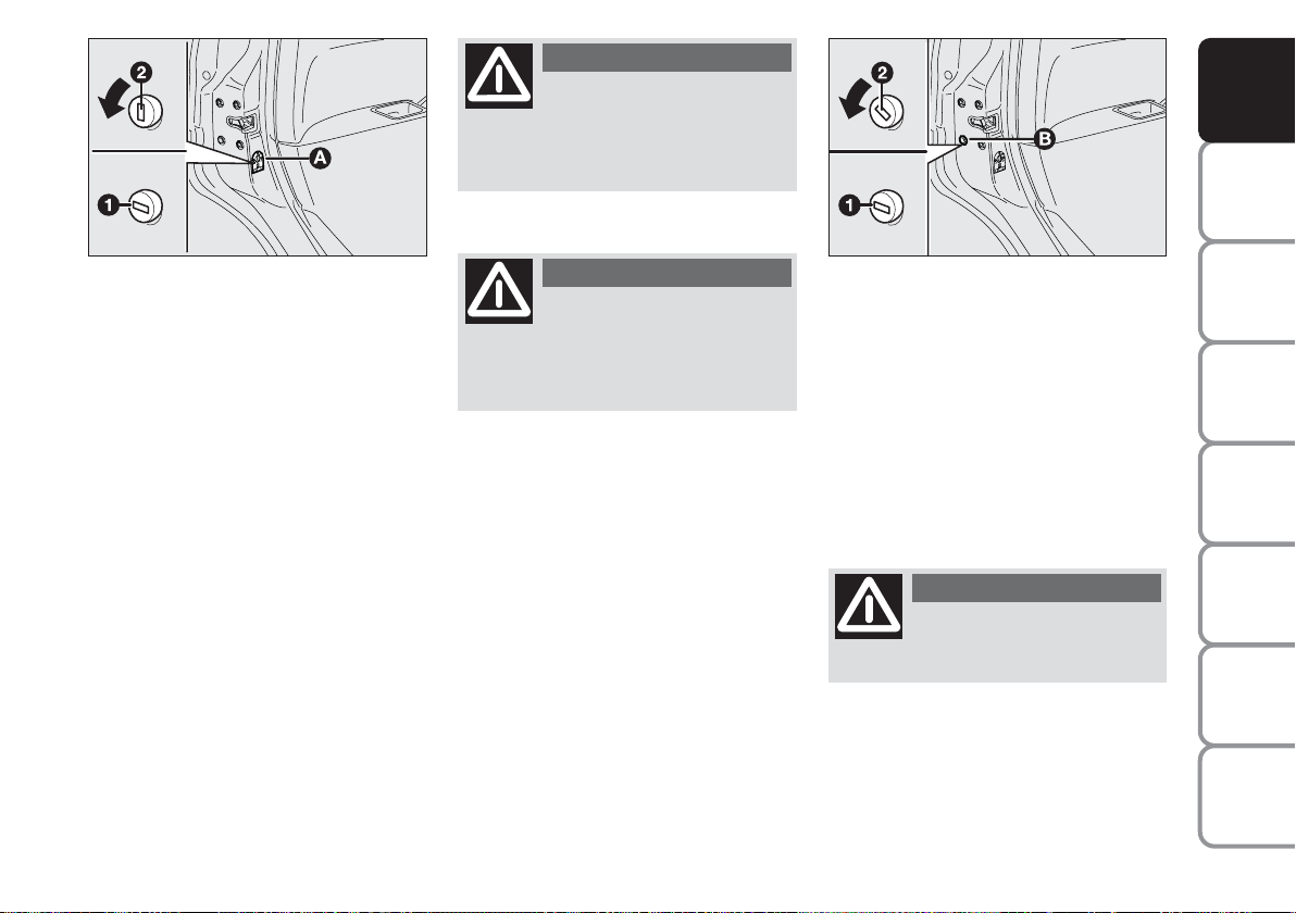
ADJUSTING
THE STEERING
WHEEL
The steering wheel can be adjusted in
both height A-fig. 54 and depth B.
Proceed as follows:
❒ release the lever by pulling it to-
wards the steering wheel (position
2);
❒ readjust the steering wheel as re-
quired;
❒ lock the lever by pushing it for-
wards (position 1).
fig. 54
L0D0382m
WARNING
The steering wheel posi-
tion must be adjusted only
with the car stationary and the engine turned off.
DASHBOARD
AND CONTROLS
SAFETY
DEVICES
AND
DRIVING
STARTING
WARNING
MESSAGES
LIGHTS AND
WARNING
When reinstalling the
headrest, make sure that
the installation direction is correct.
Then, check that the height position is locked.
WARNING
Rear cradle headrests op-
timise visibility and must
always be lifted with a passenger
in the car.
WARNING
Under no circumstances
should after-market operations involving steering system or
steering column modifications (e.g.:
installation of anti-theft device) be
carried out, because they could
badly affect performance and
safety, cause the warranty to become void and also result in car
non-compliance with homologation
requirements.
IN AN
EMERGENCY
AND CARE
MAINTENANCE
TECHNICAL
SPECIFICATIONS
INDEX
45
Page 47

DASHBOARD
AND CONTROLS
SAFETY
DEVICES
AND
DRIVING
STARTING
WARNING
MESSAGES
LIGHTS AND
IN AN
EMERGENCY
AND CARE
MAINTENANCE
TECHNICAL
SPECIFICATIONS
REARVIEW
MIRRORS
INTERNAL MIRROR
The mirror is fitted with a safety device that causes its release in the event
of a violent crash.
It can be moved using lever A-fig. 55
to two different positions: normal or
antiglare.
DOOR MIRRORS
They are adjusted electrically and this
operation is only possible with ignition key turned to MAR.
Proceed as follows:
❒ use switch B-fig. 56 to select the
mirror requiring adjustment (left
or right);
❒ adjust the mirror by moving the
switch C in the four directions.
fig. 55
L0D0056m
Adjust the mirrors after the car has
been stopped and the hand brake engaged.
The electric demisting device of the
mirrors is automatically engaged
when the rear window demister is activated.
Folding
When required (for example when the
mirror causes difficulty in narrow
spaces) it is possible to fold the mirror moving it from position 1 to position 2-fig. 57.
fig. 56
fig. 57
L0D0058m
L0D00569m
During car travel the mirrors must be kept in the
open position, 1-fig. 57.
The door mirror on the driver’s side is convex and therefore
slightly alters the perception of distance.
INDEX
46
Page 48

HEATING/CLIMATE CONTROL SYSTEM
DASHBOARD
AND CONTROLS
SAFETY
DEVICES
AND
DRIVING
STARTING
WARNING
MESSAGES
LIGHTS AND
IN AN
EMERGENCY
AND CARE
MAINTENANCE
fig. 58
L0D0383m
1. Fixed vent for side window defrosting/demisting - 2. Adjustable side air vents - 3. Fixed vents for windscreen defrosting/demisting - 4. Adjustable central vents - 5. Lower vents - 6. Lower vents for rear passengers.
TECHNICAL
SPECIFICATIONS
INDEX
47
Page 49

DASHBOARD
AND CONTROLS
SAFETY
DEVICES
MANUAL CLIMATE CONTROL SYSTEM
(where provided)
AND
DRIVING
STARTING
WARNING
MESSAGES
LIGHTS AND
IN AN
EMERGENCY
AND CARE
MAINTENANCE
TECHNICAL
SPECIFICATIONS
INDEX
48
fig. 59
fig. 60 fig. 61
CENTRAL AND SIDE VENTS
figs. 59-60
A Fixed vent for side window
demisting/defrosting.
B Control for vent opening/closing
C Control for directing the vent and
air flow.
L0D0061m
L0D0062m
CONTROLS
A knob for fan activation and speed adjustment;
B rotating knurled ring for air temperature regulation (hot/cold air mixing);
C rear window demister on/off button;
D climate control compressor on/off button;
E knurled ring for air distribution selection;
F internal air recirculation on/off knob.
L0D0064m
Page 50

AIR DISTRIBUTION
The rotating knurled ring E enables
the air in the car to reach all the areas in the passenger compartment according to 5 options:
« delivery of air from the central and
side vents 2 and 4;
Δ delivery of air from the central and
side vents 2 and 4 and downwards
5 and 6 (bilevel function);
≈ delivery of air downwards 5 and
6;
ƒ
delivery of air downwards 5 and 6
and to the windscreen 3 simultaneously;
-
demisting and defrosting of windscreen 3 and front side windows
vents 1.
REGULATING THE
TEMPERATURE
Proceed as follows:
Turn the rotating knurled ring B-fig.
61 to the right (gauge on red area) to
increase the temperature or to the left
to reduce it.
REGULATING THE FAN SPEED
To ventilate the passengers compartment properly proceed as follows:
❒ deliver air from the central and
side vents 4 and 2;
❒ position the rotating knurled ring
B-fig. 61 on the blue section;
❒ turn knob A to the required speed;
❒ position the knurled ring E on
«
❒ stop internal air recirculation by
placing knob F on
Ú
.
ACTIVATING THE INTERNAL
AIR RECIRCULATION
Position the knob F-fig. 61 on
It is advisable to activate air recycle
in queues or in tunnels to prevent the
introduction of polluted air. Do not
use the function for a long time, particularly if there are many passengers
on board, to prevent the windows
from misting up.
IMPORTANT The internal air recirculation system makes it possible to
reach the required “heating” or
“cooling” conditions faster. Do not use
the air recirculation function on
rainy/cold days as it would considerably increase the possibility of the
windows misting inside.
;
…
.
DASHBOARD
AND CONTROLS
SAFETY
DEVICES
AND
DRIVING
STARTING
WARNING
MESSAGES
LIGHTS AND
IN AN
EMERGENCY
AND CARE
MAINTENANCE
TECHNICAL
SPECIFICATIONS
INDEX
49
Page 51

DASHBOARD
AND CONTROLS
SAFETY
DEVICES
AND
DRIVING
STARTING
WARNING
MESSAGES
LIGHTS AND
IN AN
EMERGENCY
AND CARE
MAINTENANCE
FAST HEATING
Proceed as follows:
❒ close all the vents on the dash-
board;
❒ position the rotating knurled ring
B-fig. 61 on the red section;
❒ turn knob A on 4
-
;
❒ position the rotating knurled ring
E on≈.
FRONT WINDOW FAST
DEMISTING/DEFROSTING
(WINDSCREEN AND SIDE
WINDOWS)
Proceed as follows:
❒ position the rotating knurled ring
B on the red section;
❒ turn knob A on 4
-
;
❒ position the rotating knurled ring E
on-;
❒ stop internal air recirculation by
placing knob F on
Ú
.
After demisting/defrosting, operate
the controls to restore the required
comfort.
Window demisting
In the event of considerable outside
moisture and/or rain and/or considerable differences in temperature inside and outside the passenger compartment, perform the following preventive demisting procedure:
❒ stop internal air recirculation by
placing knob F-fig. 61 on
Ú
;
❒ position the rotating knurled ring
B on the red section;
❒ turn knob A on 2;
❒ position the rotating knurled ring
E on
-
with the option of shifting to position ƒif the windows
do not get misted.
IMPORTANT The climate control system is very useful to make window
demisting faster. To do this, proceed
as previously described and start the
system by pressing buttonD.
TECHNICAL
SPECIFICATIONS
INDEX
50
Page 52

DEMISTING/DEFROSTING
OF REAR WINDOW DEMISTER
AND ELECTRICAL DOOR
MIRRORS (where provided)
Press button C-fig. 61 to enable this
function. When the function is active,
a led on the button goes on.
This is a timed function, which is automatically disabled by the system after a preset time. Press button C
again to disable the function in advance.
IMPORTANT Do not affix decals on
the inside of the rear window over the
heating filaments to avoid damage
that might cause it to stop working
properly.
CLIMATE CONTROL
(cooling and de-humidification)
Proceed as follows:
❒ position the rotating knurled ring
B-fig. 61 on the blue section to
select the required temperature;
❒ turn knob A to the required speed;
❒ position the knurled ring E on
❒ position the knob F on
…
«
;
❒ press button D√(the LED on the
button goes on).
Regulating cooling
Proceed as follows:
❒ stop internal air recirculation by
placing knob F-fig. 61 on
❒ turn the rotating knurled ring B
clockwise to increase the temperature;
❒ turn knob A anticlockwise to re-
;
duce the fan speed.
SERVICING THE SYSTEM
Run the climate control system for at
least 10 minutes every month during
the winter. Have the system inspected
at a Lancia Dealership before the
summer.
Ú
DASHBOARD
;
AND CONTROLS
SAFETY
DEVICES
AND
DRIVING
STARTING
WARNING
MESSAGES
LIGHTS AND
IN AN
EMERGENCY
AND CARE
MAINTENANCE
TECHNICAL
SPECIFICATIONS
INDEX
51
Page 53

DASHBOARD
AND CONTROLS
SAFETY
DEVICES
AND
DRIVING
STARTING
WARNING
MESSAGES
LIGHTS AND
IN AN
EMERGENCY
AND CARE
MAINTENANCE
TECHNICAL
SPECIFICATIONS
INDEX
AUTOMATIC
TWO-ZONE
CLIMATE
CONTROL SYSTEM
(where provided)
INTRODUCTION
The automatic two-zone climate control system adjusts the temperature
and distribution of air in the passenger compartment in two zones: the
driver’s side and the passenger’s side.
Temperature is controlled on the basis of an “equivalent temperature”
principle. In other words, the system
continuously works to keep the comfort level inside the car constant and
to compensate for possible variations
of external conditions, including sun
radiation detected by a specific sensor.
The automatically controlled parameters and functions are:
❒ air temperature delivered to dri-
ver/front passenger vents;
❒ air distribution to driver/front pas-
senger vents;
❒ fan speed (continuous air flow
variation);
❒ compressor ON (for air
cooling/de-humidification);
❒ air recirculation.
All functions may be manually
changed. In order words, you may select one or more functions and change
the parameters as required. Automatic control of the manually
changed functions will be suspended:
the system will change override your
settings only for safety-related reasons
(e.g. risk of misting up).
Manual selections always have higher
priority over automatic settings and
are stored until the user switches the
system back to automatic control expect for cases in which the system intervenes for particular safety-related
reasons.
You can adjust one function automatically and have the automatic system
control all the others.
The amount of air delivered to the
passenger compartment depends on
the car speed, because it is regulated
by the electronic fan.
The temperature of the delivered air
is always controlled automatically depending on the temperature values set
on the driver’s and front passenger’s
display (except for cases in which the
system is OFF or the compressor disengaged).
The following parameters and functions can be set or changed manually:
❒ temperature of air on driver’s/
front passenger’s side;
❒ fan speed (continuous variation);
❒ air distribution on five levels (dri-
ver’s/front passenger’s side);
❒ climate control compressor ON;
❒ monozone/two-zone distribution
priority;
❒ fast demisting/defrosting;
❒ air recirculation;
❒ rear window demister;
❒ system deactivation.
52
Page 54

CONTROLS
A: button for activating the MONO
function (alignment of set temperatures);
B: climate control compressor on/off
button;
C: air recirculation on/off button;
D: climate control system information
display;
DASHBOARD
AND CONTROLS
SAFETY
DEVICES
AND
DRIVING
STARTING
fig. 62
E: climate control system off button;
F: button for activating the MAX-
DEF function (fast front window
defrosting/demisting);
G: rear window demister on/off but-
ton;
H: button for activating the AUTO
function (automatic operation)
and knob for setting the temperature on the passenger’s side;
I: air distribution button on passen-
ger’s side;
L0D0065m
L: fan speed increase/decrease;
M: air distribution button on driver’s
side;
N: button for activating the AUTO
function (automatic operation)
and knob for setting the temperature on the driver’s side.
WARNING
MESSAGES
LIGHTS AND
IN AN
EMERGENCY
AND CARE
MAINTENANCE
TECHNICAL
SPECIFICATIONS
INDEX
53
Page 55

DASHBOARD
AND CONTROLS
SAFETY
DEVICES
AND
DRIVING
STARTING
WARNING
MESSAGES
LIGHTS AND
IN AN
EMERGENCY
AND CARE
MAINTENANCE
USING THE CLIMATE
CONTROL SYSTEM
The system can be started in different
ways, but it is advisable to press one
of the AUTO buttons and then to turn
the knobs to set the temperatures required on the display.
As the system manages two zones in
the passenger compartment, the driver
and front passenger can select different temperature values with a maximum difference of 7 °C.
The system starts running automatically in this way in order to reach
comfortable temperature as quickly
as possible depending on the set temperature values. The system adjusts
the temperature, amount and distribution of air delivered to the passenger
compartment. In addition, it manages
the recirculation function to engage
the climate control system compressor.
During fully automatic operation, the
only functions that are enabled manually are:
❒ MONO to align the air tempera-
ture and distribution on the passenger’s side with that on the driver’s side;
❒
…
, air recirculation, to keep it
always on or off;
❒
-
to speed up demisting/defrosting of windscreen, side windows,
rear window and door mirrors;
❒
(
to demist/defrost the rear win-
dow and door mirrors.
During fully automatic operation the
set temperatures, the air distribution
and fan speed can be changed using
the corresponding supplied buttons or
knobs at any time. The system will
automatically change the settings to
adapt to the new request.
During fully automatic operation
(FULL AUTO), the word FULL will
disappear if the air distribution, air
speed, compressor and/or recirculation settings are changed. In this way,
the functions will switch from automatic to manual control until AUTO
is pressed again. There is only one fan
speed in all the areas of the passenger
compartment.
With on or more manually set functions, the delivered air temperature is
still managed automatically by the
system, except for when the compressor is off. In the case, the air delivered
into the passenger compartment cannot be cooler than the outside air.
TECHNICAL
SPECIFICATIONS
INDEX
54
Page 56

CONTROLS
Air temperature
adjusting knobs
H - N
Rotate the knobs
clockwise or anticlockwise to lift or
lower the air temperature in the front left
area (knob N) and
right left area (knob
H) of the passenger
compartment respec-
tively.
As the system manages two zones in
the passenger compartment, the driver
and front passenger can set different
temperature values with a maximum
difference of 7 °C.
The temperature values set are highlighted on the display near the knobs.
Press button A (MONO) to automatically align the temperature of the air
in the front passenger’s area and that
on the driver’s side. This means that
the same temperature can be set in
the two areas by turning knob N on
the driver’s side.
This function has been included to
make temperature regulation easier
inside the passenger compartment
when the driver is the only passenger.
For separate management of temperatures and air distribution in the two
different areas of the passenger compartment, turn knobs H or press button A-MONO again when the LED on
the button is on.
Turn the knobs either all the way
right or left to the extreme HI or LO
position to use the maximum heating
or maximum cooling functions:
❒ Function HI (max. heating):
select by turning the temperature
knob clockwise over the maximum
value (32 °C). This function is activated from either the driver’s or front
passenger’s side or both (even by selecting function MONO).
The function is enabled when the passenger compartment needs to be
heated as quickly as possible, thus using the system operating capacity at
best. This function uses the heating
fluid at max. temperature; air distribution and fan speed are managed by
the system based on the existing conditions.
Specifically, if the heating fluid is not
sufficiently warm, the fan will not
start up at the maximum speed immediately to limit introduction of excessively cool air into the passenger
compartment.
All manual settings will be allowed
when this function is on.
To switch the function off, simply turn
the temperature knob anticlockwise
and set the required temperature.
❒ Function LO (max. cooling):
select by turning the temperature
knob anticlockwise under the minimum value (16 °C). This function is
activated from either the driver’s or
front passenger’s side or both (even by
selecting function MONO).
DASHBOARD
AND CONTROLS
SAFETY
DEVICES
AND
DRIVING
STARTING
WARNING
MESSAGES
LIGHTS AND
IN AN
EMERGENCY
AND CARE
MAINTENANCE
TECHNICAL
SPECIFICATIONS
55
INDEX
Page 57

DASHBOARD
AND CONTROLS
SAFETY
DEVICES
AND
DRIVING
STARTING
WARNING
MESSAGES
LIGHTS AND
IN AN
EMERGENCY
AND CARE
MAINTENANCE
The function is enabled when the passenger compartment needs to be
cooled as quickly as possible, thus using the system operating capacity at
best. This function enables air recirculation and engages the climate control system compressor; air distribution and fan speed are managed by
the system based on ambient conditions. All manual settings will be allowed when this function is on.
To switch the function off, simply turn
the temperature knob clockwise and
set the required temperature.
Air distribution
buttons I-M
Pressing these buttons it is possible to
manually set one of
the five possible air
distribution modes to
the passenger compartment (right or
left side):
▲ air flow to the windscreen and
front side window vents to demist
or defrost them;
˙ air flow at central and side dash-
board vents to ventilate the chest
and the face during the hot season;
▼ air flow to the front and rear foot
well vents. Thanks to the natural
upwards movement of heat, this
type of distribution is the quickest
for heating the passenger compartment offering the passenger(s)
a prompt feeling of heated air.
˙
Air flow distributed between the
▼
foot well vents (hotter air) and the
central and side dashboard vents
(cooler air). This distribution
mode is particularly useful in
spring and autumn on a sunny
day.
▲
Air flow distributed between foot
▼
well vents and windscreen and
front side window
defrosting/demisting vents. This
distribution mode enables proper
heating of the passenger compartment, thus preventing possible
window misting.
TECHNICAL
SPECIFICATIONS
INDEX
56
Page 58

The distribution mode set is indicated
by the LEDs that light up on the selected buttons.
In combined function mode the relevant function is enabled simultaneously with those already set by pressing the corresponding button. If a
button is pressed for a function that
is active, the operation is cancelled
and the corresponding LED goes off.
To restore automatic air distribution
control after a manual selection, press
button AUTO.
When the driver selects air distribution to the windscreen, the air distribution on the passenger’s side too is
aligned to the windscreen. The passenger can select a different distribution mode by pressing the corresponding buttons.
Fan speed
adjustment buttons
L
Press the ends of button
p
to increase or to
decrease the fan speed and consequently the amount of air delivered to
the passenger compartment, although
keeping the required temperature setting.
The fan speed is shown by the lit bars
on the display.
❒ Max. fan speed = all bars lit;
❒ Min. fan speed = one bar lit.
The fan can be cut off only if the climate control compressor has been
switched off pressing button B.
IMPORTANT To restore automatic
fan speed control after a manual adjustment, press button AUTO.
Buttons
AUTO H-N
(automatic
operation)
Press button AUTO on
the driver’s side and/or
front passenger’s side
to automatically adjust
the amount and distribution of air delivered
to the passenger com-
partment, thus cancelling the previously made manual adjustments.
The message FULL AUTO will appear on the front display in this condition.
When at least one of the functions
managed by the system is manually
changed (air recirculation, air distribution, fan speed or climate control
system compressor off), the message
FULL on the display goes off to indicate that the system is no longer
checking all the functions one by one
(the temperature is still automatic).
DASHBOARD
AND CONTROLS
SAFETY
DEVICES
AND
DRIVING
STARTING
WARNING
MESSAGES
LIGHTS AND
IN AN
EMERGENCY
AND CARE
MAINTENANCE
TECHNICAL
SPECIFICATIONS
INDEX
57
Page 59

DASHBOARD
AND CONTROLS
SAFETY
DEVICES
AND
DRIVING
STARTING
WARNING
MESSAGES
LIGHTS AND
IN AN
EMERGENCY
AND CARE
MAINTENANCE
IMPORTANT If the system can no
longer guarantee achievement or
preservation of the required temperature in the different areas of the passenger compartment due to manual
adjustments of the functions, the set
temperature value flashes, thus indicating a system fault. One minute
later the message AUTO goes off.
To restore system automatic control at
any time, after one or more manual
selections, press button AUTO.
Button MONO A
(to align set
temperatures and
air distribution)
Press button MONO
to automatically align the air temperature and distribution in the front
passenger’s area and that on the driver’s side. This means that the same
temperature can be set in the two areas by turning the knob on the driver’s side. This function makes temperature regulation easier inside the
passenger compartment when the driver is the only passenger. For separate
management of temperatures and air
distribution in the two different areas
of the passenger compartment, turn
knob H or press button MONO A
again when the LED on the button is
on.
Air recirculation
on/off button C
Air recirculation is
managed according to
the following operating logics:
❒ override on (air recirculation al-
ways on), indicated by the active
LED on button C and symbol
í
on the display;
❒ override off (air recirculation al-
ways off and introduction of external air), indicated by the inactive LED on the button and the
symbol
on the display.
ê
These operating conditions are obtained by pressing the air recirculation button C in sequence.
For safety reasons, the system automatically disengages air recirculation
after a pre-set time, thus letting fresh
air in.
TECHNICAL
SPECIFICATIONS
INDEX
58
Page 60

IMPORTANT Air recirculation ON
enables faster achievement of the desired conditions (for passenger compartment heating or cooling). It is
however inadvisable to use it on
rainy/cold days as it would considerably increase the possibility of the
windows misting inside, especially if
the climate control compressor is off.
Recirculation is forced to off (i.e. air
is introduced from the outside) when
the outside temperature is inferior to
5-7°C to prevent misting up.
WARNING
It is advisable not to use
the air recirculation function when the outside temperature
is low to prevent the windows from
rapidly misting up.
Climate control
compressor on/off
button B
Press button √when
the LED on it goes on.
The LED goes off when the climate
control compressor is switched off.
Press the button when the LED is off
to automatically restore system control and use of the compressor. Successful completion of this operation is
highlighted by the button LED
switching on.
The system will switch recirculation
off when the compressor is switched
to off to prevent windows from misting up. Although the system is capable of maintaining the required temperature, the word FULL will disappear from the display. If on the other
hand the system cannot maintain the
required temperature, the digits will
blink and the word AUTO will disappear.
IMPORTANT With the compressor
off, it is not possible to introduced air
cooler than ambient temperature into
the passenger compartment. Furthermore, in certain conditions, the windows could mist up rapidly because
the air is not dehumidified.
DASHBOARD
AND CONTROLS
SAFETY
DEVICES
AND
DRIVING
STARTING
WARNING
MESSAGES
LIGHTS AND
IN AN
EMERGENCY
AND CARE
MAINTENANCE
TECHNICAL
SPECIFICATIONS
59
INDEX
Page 61

DASHBOARD
AND CONTROLS
SAFETY
DEVICES
AND
DRIVING
STARTING
WARNING
MESSAGES
LIGHTS AND
IN AN
EMERGENCY
AND CARE
MAINTENANCE
Disengagement of the compressor remains stored even after the engine
stops.
To restore automatic compressor control, press button √again (in this
case, the system will only work as a
heater) or press AUTO.
With climate control compressor off if
the outside temperature is higher than
the one set, the system will not be able
to keep the required condition, the
temperature value will then start
flashing on the display for a few seconds and the message AUTO goes off.
With climate control compressor off,
the fan speed can be set to zero manually (no bar shown).
With the compressor enabled and the
engine started, the fan speed may be
reduced to the minimum setting only
(one bar shown).
Fast window
demisting/
defrosting button F
Press this button: the
climate control system
will automatically switch on all the
functions required for fast windscreen
and front side window demisting/defrosting, that is:
❒ switches on the climate control
compressor when weather conditions are suitable;
❒ disables air recirculation;
❒ sets the maximum air temperature
HI in both areas;
❒ sets proper fan speed according to
engine coolant temperature to
limit the flow of not sufficiently
warm air to demist the windows
into the passenger compartment;
❒ directs the air flow to the wind-
screen and front side windows
vents;
❒ engages the rear window mister.
IMPORTANT The fast window
demisting/defrosting function remains
engaged for approx. 3 minutes starting from the time when the engine
coolant exceeds 50°C (petrol versions)
or 35°C (Multijet versions).
When this function is active, the LED
of the corresponding button switches
on and that of the rear window
demister. The text FULL AUTO goes
off on the display.
You can only adjust the fan speed and
switch the rear window demister off
manually when this function is active.
To restore operating conditions before
this function is activated, press button F, the air recirculation button C,
the compressor button B or button
AUTO N or H.
TECHNICAL
SPECIFICATIONS
INDEX
60
Page 62

Demisting/
defrosting button
for rear window
and door mirrors G
Press this button to
activate heated rear window demisting/defrosting. When this function is
on, the button led is on.
This function switches off automatically after a pre-set time or by pressing again the button or by turning the
engine off. It will not be switched on
automatically when restarting the engine.
IMPORTANT Do not affix decals on
the inside of the rear window over the
heating filaments to avoid damage
that might cause it to stop working
properly.
Switching the
system OFF E
Press button E to
switch the climate
control system off.
The display will go
out as a consequence.
The following climate control conditions will be established when the system is off:
❒ LEDs are off;
❒ temperatures set are not displayed;
❒ air recirculation is enabled, thus
isolating the passenger compartment from external conditions;
❒ the climate control compressor is
off;
❒ the fan is off.
With the system OFF the rear window
demister can either be enabled or disabled manually by pressing button G.
IMPORTANT The system unit stores
the temperatures set before turning
off and resets them when pressing any
button (except heated rear window).
If the function corresponding to the
button pressed is off, it will be turned
on; if on, it will be kept active.
Press button AUTO to switch the the
climate control system on in automatic mode.
DASHBOARD
AND CONTROLS
SAFETY
DEVICES
AND
DRIVING
STARTING
WARNING
MESSAGES
LIGHTS AND
IN AN
EMERGENCY
AND CARE
MAINTENANCE
TECHNICAL
SPECIFICATIONS
INDEX
61
Page 63

DASHBOARD
AND CONTROLS
SAFETY
DEVICES
AND
DRIVING
STARTING
WARNING
MESSAGES
LIGHTS AND
IN AN
EMERGENCY
AND CARE
MAINTENANCE
TECHNICAL
SPECIFICATIONS
INDEX
EXTERNAL LIGHTS
The left-hand lever includes the controls for the external lights.
The external lights can only be
switched on when the ignition key is at
MAR.
LIGHTS OFF fig. 63
Knurled ring turned to position
SIDE/TAILLIGHTS fig. 64
Turn the knurled ring to position 6.
The warning light 3on the instrument panel comes on at the same time.
DIPPED BEAM HEADLIGHTS
fig. 65
Turn the knurled ring to position
The warning light 3on the instrument panel comes on at the same time.
BEAM HEADLIGHTS fig. 66
When the knurled ring is in position
pull the lever towards the steering
wheel (stable position). The warning
light1on the instrument panel comes
on at the same time.
To turn the beam headlights off, pull
again the lever towards the steering
wheel (dipped beams will turn on
again).
å
.
2
.
2
fig. 63
fig. 64
L0D0066m
L0D0067m
FLASHING THE HEADLIGHTS
Pull the stalk towards the steering
wheel (unstable position) regardless
of the position of the knurled ring.
The warning light
on the instru-
1
ment panel will come on at the same
time.
fig. 65
fig. 66
L0D0068m
L0D0069m
PARKING LIGHTS fig. 67
With the ignition key in position
STOP or removed, rotate knurled ring
in position
. The warning light
6
3
is lit on the instrument panel and all
the plate lights and side/taillights go
on. Move the lever aupwards to turn
on the lights on the right-hand side;
b
move it downwards
to turn on the
lights on the left-hand side. In both
cases the warning light 3on the instrument panel does not turn on.
62
Page 64

DASHBOARD
AND CONTROLS
SAFETY
DEVICES
fig. 67
L0D0071m
DIRECTION INDICATORS
fig. 67
Push the stalk to (stable) position:
❒ up (position 1): right-hand indica-
tor ON;
❒ down (position 2): left-hand indi-
cator ON.
Warning light
ForD
start flashing
on the instrument panel.
Indicators are switched off automatically when the steering wheel is
straightened.
If you want the indicator to flash
briefly to show that you are about to
change lane, move the stalk up or
down without clicking into position
(unstable position). When released,
the stalk will return to its home position.
fig. 68
L0D0070m
“FOLLOW ME HOME”
DEVICE fig. 68
This function allows the illumination
of the space in front of the car for a
preset period of time.
Activation
With the ignition key on STOP or removed, pull the stalk towards the
steering wheel within 2 minutes from
when the engine is turned off.
At each single movement of the stalk,
the time in which the lights stay on is
extended by 30 seconds up to maximum 210 seconds. After this time, the
lights go off automatically.
fig. 69
L0D0072m
AUTOMATIC LIGHT SENSORS
(dusk sensor) (where provided)
This sensor detects any changes in the
external brightness according to the
sensitivity of the set light level: the
higher the sensitivity, the lower the
amount of external light needed to
switch the lights on. The sensitivity of
the dusk sensor is adjusted by means
of the “Setup menu” on the “Multifunctional Display”.
Activation
Rotate the knurled ring in position
2
fig. 69 as to cause automatic switching on of the side/tail lights and low
beam lights simultaneously depending on the external brightness.
AND
DRIVING
STARTING
WARNING
MESSAGES
LIGHTS AND
IN AN
EMERGENCY
A
AND CARE
MAINTENANCE
TECHNICAL
SPECIFICATIONS
INDEX
63
Page 65

DASHBOARD
AND CONTROLS
SAFETY
DEVICES
AND
DRIVING
STARTING
WARNING
MESSAGES
LIGHTS AND
IN AN
EMERGENCY
AND CARE
MAINTENANCE
TECHNICAL
SPECIFICATIONS
INDEX
fig. 70
L0D0384m
When the automatic light sensor is activated, the multifunctional display
shows the pre-set sensor sensitivity
level. On this screen it is possible to
adjust the sensitivity level using the
buttons
+ and –
(see fig. 70).
Deactivation
The main beam headlights will go out
followed by the side/tail lights after
approximately 10 seconds, when the
sensor is deactivated.
If the beam headlights are enabled
(manually by the driver) during automatic lighting, the beam lights go
off automatically along with the
lights.
IMPORTANT The sensor cannot detect the presence of fog. So, in foggy
conditions, switch the lights on manually.
WINDOW
WASHING
WINDSCREEN
WASHER/WIPER
The device can work only when the
ignition key is on MAR.
The right lever can take five different
positions:
A windscreen wiper off
B intermittent.
With the lever in position B, turn the
knurled ring F to select one of four
different speeds for the intermittent
operation mode:
,
= very slow intermittence
--
= slow intermittence
---
= mean intermittence
----
= fast intermittence
fig. 71
C continuous slow operation;
D continuous fast operation
E temporary fast operation
(unstable position).
L0C0073m
64
Page 66

Operation in position E is limited to
the time during which the lever is
kept in that position manually..
When released, the stalk will return
to position A and the wiper will be
automatically stopped.
IMPORTANT Replace wiper blades
as specified in section “Car
maintenance”.
Do not use the windscreen
wiper to remove layers of
snow or ice from the wind-
screen. In such conditions,
the windscreen wiper may be subjected to excessive stress and the
motor protection which prevents operation for a few seconds may trip.
If the issue persists, contact the Lancia Dealership.
fig. 72
L0D0074m
“Smart washing” function
Pull the stalk towards the steering
wheel (unstable position) to operate
the windscreen washer.
Keeping the stalk pulled for more
than half a second, with just one
movement it is possible to operate the
washer jet and the wiper at the same
time.
When releasing the stalk, the jet stops
immediately, while the wiper carries
out another four strokes.
A further stroke after 6 seconds completes the wiping operation.
RAIN SENSOR
(where provided)
The rain sensor is located behind the
driving mirror in contact with the
windscreen and has the purpose of
automatically adjust the frequency of
the windscreen wiper strokes as to the
rain intensity.
IMPORTANT Keep the window clean
in the sensor area.
Activation
Move the right lever down by one
click.
The activation of the rain sensor is
signalled by a control acquisition
“stroke”.
Turn the knurled ring F-fig. 73 to increase the rain sensor sensitivity.
The increase of the sensitivity of the
rain sensor is signalled by a control
and acquisition “stroke”.
By operating the windscreen washer
with the rain sensor enabled, a smart
washing cycle is carried out, without
the additional stroke after 5 seconds;
once completed, the sensor resumes its
regular automatic operation.
DASHBOARD
AND CONTROLS
SAFETY
DEVICES
AND
DRIVING
STARTING
WARNING
MESSAGES
LIGHTS AND
IN AN
EMERGENCY
AND CARE
MAINTENANCE
TECHNICAL
SPECIFICATIONS
65
INDEX
Page 67

DASHBOARD
AND CONTROLS
SAFETY
DEVICES
AND
DRIVING
STARTING
WARNING
MESSAGES
LIGHTS AND
IN AN
EMERGENCY
AND CARE
MAINTENANCE
TECHNICAL
SPECIFICATIONS
INDEX
fig. 73
L0C0073m
Deactivation
Change the stalk knurled ring position from B or turn the ignition key to
STOP.
At the next start-up (key at MAR),
the sensor will not be reactivated even
if the stalk is at B. To activate the sensor, move the stalk to position A or C
and then to position B or turn the sensitivity adjustment knurled ring.
The sensor reactivation is signalled by
a windscreen wiper “stroke”.
The rain sensor is able to recognize
and automatically adjust itself in the
presence of the following particular
conditions:
❒ impurities on the controlled sur-
face (salt, dirt, etc.);
❒ difference between day and night.
WARNING
Streaks of water may
cause unnecessary blade
moving.
REAR WINDOW WASHER/
WIPER fig. 74
The device can work only when the
ignition key is on MAR.
Turning the knurled ring A from positionåto position ' will operate the
rear window wiper as follows:
❒ intermittent operation if the
windscreen wiper is off;
❒ synchronised with the windscreen
wiper (but with half stroke frequency);
fig. 74
L0D0075m
With windscreen wiper on and reverse
gear engaged, rear window wiping
will be continuous.
Pushing the stalk towards the dashboard (unstable position) will activate
the rear window washer.
Keeping the stalk pushed for over half
a second will activate also the rear
window wiper.
Releasing the stalk will activate the
smart washing function as described
for the windscreen wiper.
66
Page 68

CRUISE CONTROL
(constant speed
regulator)
(where provided)
It is a device able to support the driver, with electronic control, which allows driving at speed over 30 km/h
on long and straight dry roads (e.g.:
motorways), at a desired speed, without pressing the accelerator pedal.
Therefore it is not suggested to use
this device on extra-urban roads with
traffic. Do not use it in town.
fig. 75
L0D0076m
DEVICE ENGAGEMENT
Turn the knurling ring A-fig. 75 to
ON.
The device must be enabled only with
th
4
or 5thgear engaged. Travelling
downhill with the device engaged, the
car speed may increase more than the
memorised one. When the device is
activated the instrument panel warning light Ü turns on and the relevant
message (where provided) is displayed on the multifunctional display.
TO MEMORISE SPEED
Proceed as follows:
❒ turn knurling ring A-fig. 75 to ON
and press the accelerator pedal to
the required speed;
❒ push the lever up (+) for at least
three seconds, then release it: the
car speed will be stored. The accelerator pedal may be released.
If needed (e.g. for overtaking), press
the accelerator pedal to accelerate: the
car will return to the previously set
speed when the pedal is released.
DASHBOARD
AND CONTROLS
SAFETY
DEVICES
AND
DRIVING
STARTING
WARNING
MESSAGES
LIGHTS AND
IN AN
EMERGENCY
AND CARE
MAINTENANCE
TECHNICAL
SPECIFICATIONS
INDEX
67
Page 69

DASHBOARD
AND CONTROLS
SAFETY
DEVICES
AND
DRIVING
STARTING
WARNING
MESSAGES
LIGHTS AND
IN AN
EMERGENCY
AND CARE
MAINTENANCE
TECHNICAL
SPECIFICATIONS
RESTORING STORED SPEED
If the device has been disengaged for
example pressing the brake or clutch
pedal, the memorised speed can be reset as follows:
❒ accelerate gradually until reaching
a speed approaching the one
memorised;
❒ engage the gear selected at the
time of speed memorising (4
th
or
5thgear);
❒ press the button RES B.
TO INCREASE THE
MEMORISED SPEED
The stored speed can be increased
in two ways:
❒ pressing the accelerator and then
memorising the new speed
reached;
or
❒ moving the stalk upwards (+).
Each operation of the stalk will correspond to a slight increase in speed
(about 1 km/h), while keeping the
stalk upwards will correspond to a
continuous speed increase.
TO REDUCE MEMORISED
SPEED
The stored speed can be increased in
two ways:
❒ disengaging the device and then
memorising the new speed;
or
❒ moving the stalk downwards (
–)
until reaching the new speed which
will be memorised automatically.
Each operation of the stalk will correspond to a slight reduction in speed
(about 1 km/h), while keeping the
stalk downwards will correspond to a
continuous speed reduction.
DEVICE DISENGAGEMENT
Turn the knurled ring A-fig. 75 to
OFF or the ignition key to STOP. In
addition, the device is automatically
disengaged in one of the following
cases:
❒ pressing the brake pedal.
WARNING
While travelling with the
device engaged, do not set
the gearshift lever to neutral.
WARNING
In case of malfunctioning
or fault of the device, turn
the knurled ring to OFF and contact the Lancia Dealership, after
checking that the protection fuse is
not blown.
INDEX
68
Page 70

LIGHTS
FRONT LIGHT fig. 76
Switch A- turn on/off these lights.
With switch A in central position,
lights C and D will turn on/off when
opening/closing the front doors.
With switch A pressed on the left side,
lights C and D will always stay off.
With switch A pressed on the right
side, lights C and C will always stay
on.
Light turning on/off is gradual.
Switch B performs the spot function;
with light off, it will turn on:
❒ light C if pressed on the left side;
❒ light D if pressed on the right side.
fig. 76
L0D0077m
IMPORTANT Before getting out of
the car, make sure the switch is at
central position: lights off with doors
closed in order to avoid draining the
battery.
In any case, if the switch is left inadvertently to the On position, the lights
will turn off automatically 15 minutes
after turning the engine off.
Ceiling light timing
To facilitate getting in/out of the car
at night or with poor lighting, 2 different timed switching on modes have
been provided:
Light timing when getting into the
car
Lights will turn on as follows:
❒ for about 10 seconds when un-
locking the doors;
❒ for about 3 minutes when opening
one of the doors;
❒ for about 10 seconds when closing
the doors (within 3 minutes).
Timing will stop when turning the ignition key to MAR.
Light timing when getting out of the
car
After removing the key from the ignition switch, the lights will turn on as
follows:
❒ within 2 minutes from turning the
engine off for about 10 seconds;
❒ when opening one of the doors for
about 3 minutes;
❒ when closing the doors for about
10 seconds (within 3 minutes).
Timing will stop automatically when
locking the doors.
DASHBOARD
AND CONTROLS
SAFETY
DEVICES
AND
DRIVING
STARTING
WARNING
MESSAGES
LIGHTS AND
IN AN
EMERGENCY
AND CARE
MAINTENANCE
TECHNICAL
SPECIFICATIONS
69
INDEX
Page 71

DASHBOARD
AND CONTROLS
SAFETY
DEVICES
AND
DRIVING
STARTING
WARNING
MESSAGES
LIGHTS AND
IN AN
EMERGENCY
AND CARE
MAINTENANCE
TECHNICAL
SPECIFICATIONS
fig. 77
L0D0078m
REAR LIGHT
The light will turn on/off by pressing
the movable lens rightwards or leftwards as shown in fig. 77.
If the box is longitudinal to the roof
panel, the light is integrated into the
box itself.
If the car is equipped with a sunroof,
two 5W lights are fitted in the rear
roof panel fig. 78.
fig. 78
L0D0254m
Light timing (where provided)
To facilitate getting in/out of the car
at night or with poor lighting, 2 different timed switching on modes have
been provided:
Light timing when getting into the
car
Lights will turn on as follows:
❒ for about 10 seconds when un-
locking the doors;
❒ for about 3 minutes when opening
one of the doors;
❒ for about 10 seconds when closing
the doors (within 3 minutes).
Timing will stop when turning the ignition key to MAR.
Light timing when getting out of the
car
After removing the key from the ignition switch, the lights will turn on as
follows:
❒ within 2 minutes from turning the
engine off for about 10 seconds;
❒ when opening one of the doors for
about 3 minutes;
❒ when closing the doors for about
10 seconds (within 3 minutes).
Timing will stop automatically when
locking the doors.
INDEX
70
Page 72

LIGHT CONTROL
BUTTONS
HAZARD LIGHTS fig. 79-80
They turn on by pressing switch A,
regardless of the position of the ignition key.
When the function is active, the
switch flashes and warning lights Î
and ¥ on the panel blink.
Press the switch again to turn the
lights off.
FRONT FOG LIGHTS
(where provided) fig. 81
To turn front fog lights on, press button
5
, to activate these lights it is
necessary to have the side/taillights
switched on.
To turn them off, press again the
switch or turn the side/taillights off.
fig. 79
fig. 80
L0D0080m
L0D0081m
WARNING
The use of hazard lights is
governed by the Highway
Code of the country you are in.
Keep to the rules.
fig. 81
fig. 82
L0D0385m
L0D0386m
REAR FOG LIGHTS fig. 82
They turn on, with low beams or front
fog lights on, pressing the button
4
To turn them off, press again the
switch or turn the low beams or front
fog lights off.
DASHBOARD
AND CONTROLS
SAFETY
DEVICES
AND
DRIVING
STARTING
WARNING
MESSAGES
LIGHTS AND
IN AN
EMERGENCY
AND CARE
.
MAINTENANCE
TECHNICAL
SPECIFICATIONS
71
INDEX
Page 73

DASHBOARD
AND CONTROLS
SAFETY
DEVICES
AND
DRIVING
STARTING
WARNING
MESSAGES
LIGHTS AND
IN AN
EMERGENCY
AND CARE
MAINTENANCE
INERTIAL FUEL
CUT-OFF SWITCH
It is located in the bottom, near the
passenger side pillar; to access it, remove the carpet. It trips in the event
of a collision cutting the fuel supply
off; as a consequence, the engine turns
off.
When the switch trips, the instrument
panel warning light èturns on and
the relevant message (where provided) is displayed on the reconfigurable multifunctional display.
Carefully inspect the car to ensure
that there are no fuel leaks, e.g. from
the engine compartment, under the
car or near the tank.
fig. 84
L0D0388m
If no fuel leaks are detected and the
car can start, press button A-fig. 84
in order to reactivate the fuel feeding
system and turn the lights on.
After a crash, turn the ingition key to
STOP to avoid draining the battery.
WARNING
If, after a crash, you smell
fuel or see leaks from the
fuel system, do not reset the switch
to avoid fine risk.
TECHNICAL
SPECIFICATIONS
INDEX
72
Page 74

INTERNAL
EQUIPMENT
UPPER ODDMENT DRAWERS
fig. 85-86
To open the drawers, unlock the desired cover by means of the device A
and lift it to the stable opening position.
WARNING
Do not travel with the
oddment drawers open:
they could hurt the passengers in
case of crash.
ODDMENT COMPARTMENTS
The oddment compartment A-fig. 87
is located in the dashboard, opposite
to the front passenger.
An extractable oddment bag E-fig.
89, belonging to the Lineaccessori
Lancia range, can be placed inside the
compartment A.
Compartment B-fig. 88 is located in
the dashboard, on the left of the steering wheel.
fig. 85
fig. 86
L0D0389m
L0D0087m
Compartment C-fig. 89 and com-
partment DIN D-fig. 89 are located
in the dashboard, in central position.
Compartment DIN D can be removed
in order to install the sound system
from the Lineaccessori Lancia range.
fig. 87
fig. 88
fig. 89
L0D0088m
L0D0418m
L0D0090m
DASHBOARD
AND CONTROLS
SAFETY
DEVICES
AND
DRIVING
STARTING
WARNING
MESSAGES
LIGHTS AND
IN AN
EMERGENCY
AND CARE
MAINTENANCE
TECHNICAL
SPECIFICATIONS
INDEX
73
Page 75

DASHBOARD
AND CONTROLS
SAFETY
DEVICES
AND
DRIVING
STARTING
WARNING
MESSAGES
LIGHTS AND
IN AN
EMERGENCY
AND CARE
MAINTENANCE
TECHNICAL
SPECIFICATIONS
INDEX
74
fig. 90
fig. 91
L0D0343m
L0D0153m
DOOR POCKETS fig. 91
Paper/map pockets are located in
door panels.
fig. 92
fig. 93
L0D0091m
L0D0092m
GLASS RECESS –
CAN RECESS fig. 92
The glass/can recesses are located on
the central console in front of the
handbrake.
CARD RECESS fig. 93
The central console features recesses
to keep telephone cards, magnetic
cards or motorway tickets.
fig. 94
L0D0093m
ODDMENT SHELF
ON ROOF PANEL fig. 94
The shelf is used to rapidly store light
objects (e.g. documents, maps etc.)
IMPORTANT Do not store heavy objects on the shelf nor hang on to it.
The shelf is alternative to the sunroof.
Page 76

REAR CD
COMPARTMENT WITH
CAN RECESS fig. 95
A CD compartment with a can recess
is located on the central console, behind the handbrake.
CURRENT OUTLETS (12V)
They can only operate with ignition
key at MAR.
Outlet A-fig. 96 is located in the
front; if the car is equipped with a
“smoking kit”, outlet A is replaced by
the cigar lighter. Where provided, the
car can also be equipped with a current outlet C-fig. 98 on the left side of
the luggage compartment.
fig. 95
fig. 96
L0D0236m
L0D0236m
SMOKING KIT
(where provided)
CIGAR LIGHTER fig. 99
It is located on the central console
near the handbrake.
Press the button with the ignition key
at MAR; after 15 seconds the button
reverts automatically to its initial position and the cigar lighter is ready for
use.
IMPORTANT Always check that the
cigar lighter has turned off.
ASHTRAY fig. 100
The ashtray is a removable plastic box
with spring loaded opening that can
be fitted into the glass/can recesses on
the central console.
IMPORTANT Do not use the box as
an ashtray and a waste paper basket
at the same time: it might set on fire
in contact with cigarette stubs.
DASHBOARD
AND CONTROLS
SAFETY
DEVICES
AND
DRIVING
STARTING
WARNING
MESSAGES
LIGHTS AND
IN AN
EMERGENCY
AND CARE
MAINTENANCE
fig. 97
L0D0095m
TECHNICAL
SPECIFICATIONS
INDEX
75
Page 77

SUN VISORS
SUNROOF
DASHBOARD
AND CONTROLS
SAFETY
DEVICES
AND
DRIVING
STARTING
WARNING
MESSAGES
LIGHTS AND
IN AN
EMERGENCY
AND CARE
MAINTENANCE
TECHNICAL
SPECIFICATIONS
fig. 99
fig. 100
L0D0096m
L0D0097m
WARNING
The cigar lighter becomes
very hot. Handle with
care. The device must not be used
by children: risk of fire and/or
burns.
These are arranged at the sides of the
internal rearview mirror. They may be
oriented frontally and to the side.
On certain versions, a courtesy mirror
can be applied to the back of the sun
visor.
To use the mirror, open the sliding
door A-fig. 100 (where provided).
(where provided)
Sunroof is fitted with anti-crushing
safety system that detects the presence
of an obstacle during sunroof closing
stroke and that cuts in by stopping
and reversing the sunroof stroke. The
“skydome” sunroof is made of 2 glass
panels, one fixed and the other movable, equipped with manually operated two-position (open/closed) sun
curtains. The sunroof can be operated
only when the ignition key is on
MAR. The opening/closing functions
are controlled by the button located
near the front light.
To open
Press and keep pressed button B-fig.
101, the front pane will set to the
“spoiler” position; press button
Bagain for over half a second to make
the sunroof sliding automatically to
the wide open position; press the button to stop the sunroof at an intermediate position.
INDEX
76
Page 78

fig. 101
L0D0098m
To close
When in wide open position, press
button A-fig. 101 for over half a second to set the front pane to the
“spoiler” position; press the button
again to stop the sunroof at an intermediate position; press button A again
and keep it pressed to close the sunroof completely.
fig. 102
L0D0099m
EMERGENCY
OPENING/CLOSING
If the switch does not work, the sunroof can be operated manually as follows:
❒ remove the protection cap set be-
tween the two sun curtains;
❒ take the Allen wrench provided
❒ fit the wrench into A-fig. 102 and
turn it:
– clockwise to open the sunroof
– counter-clockwise to close the
sunroof.
If a cross roof rack is fitted,
the sunroof should be used
in the “spoiler” position
only.
Do not open the sunroof
with snow or ice to avoid
damage.
WARNING
Always remove the igni-
tion key when you get out
of the car to prevent the sunroof
being operated accidentally and
constituting a danger to the people
left in the car. The improper use of
the sunroof can be dangerous. Before and during its operation ensure that any passengers are not at
risk from the moving roof either by
personal objects getting caught in
the mechanism or by being injured
by it directly.
DASHBOARD
AND CONTROLS
SAFETY
DEVICES
AND
DRIVING
STARTING
WARNING
MESSAGES
LIGHTS AND
IN AN
EMERGENCY
AND CARE
MAINTENANCE
TECHNICAL
SPECIFICATIONS
INDEX
77
Page 79

DASHBOARD
AND CONTROLS
SAFETY
DEVICES
AND
DRIVING
STARTING
WARNING
MESSAGES
LIGHTS AND
IN AN
EMERGENCY
AND CARE
MAINTENANCE
WINDOW
WINDERS
POWER WINDOWS
The 2 button version (front power
windows only) does not feature automatic lifting or lowering, while the 4
button version (front and rear power
windows) is equipped with automatic
lifting and lowering on the driver’s
side, automatic lowering on the passenger’s side (also automatic lifting,
where provided) and automatic lowering only for rear power windows.
IMPORTANT With ignition key at
STOP or removed, the power windows remain activated for about 2
minutes and are deactivated immediately the moment a door is opened.
fig. 103
L0D0103m
DRIVER’S SIDE DOOR fig. 103
Two or five switches (where provided)
located on the internal armrest are
used, with ignition key at MAR:
A to open/close the left front win-
dow;
B to open/close the right front win-
dow;
C to open/close the left rear window
(where provided);
D to open/close the right rear win-
dow (where provided);
E to inhibit rear door controls
(where provided). When the device is activated, the LED on the
button goes on.
TECHNICAL
SPECIFICATIONS
INDEX
78
Page 80

Automatic continuous operation
(where provided)
Some versions feature four power
windows with automatic lifting and
lowering of the front window (driver’s
side) and automatic lowering only of
the other windows.
A Button for continuous auto-
matic opening and closing;
B-C-D Buttons for continuous auto-
matic opening only.
By pressing one of the buttons briefly,
the window moves “in pulse mode”
and stops on releasing the button.
PASSENGER’S SIDE DOOR
AND REAR DOORS (where
provided) fig. 104
The switch controlling the corresponding window is located on the internal armrest of each door.
fig. 104
L0D0103m
WARNING
Incorrect use of the power
windows may be dangerous. Before operation, always
check that no-one is exposed to the
risk of being injured by directly by
the moving window or objects getting caught and dragged. When
leaving the car, always remove the
key from the ignition device to
avoid the risk of injury due to accidental operation of the power
windows.
fig. 105
L0D0156m
MANUAL (where provided)
To open and to close the window use
the relevant window winder fig. 105.
DASHBOARD
AND CONTROLS
SAFETY
DEVICES
AND
DRIVING
STARTING
WARNING
MESSAGES
LIGHTS AND
IN AN
EMERGENCY
AND CARE
MAINTENANCE
TECHNICAL
SPECIFICATIONS
INDEX
79
Page 81

DASHBOARD
AND CONTROLS
SAFETY
DEVICES
AND
DRIVING
STARTING
WARNING
MESSAGES
LIGHTS AND
IN AN
EMERGENCY
AND CARE
MAINTENANCE
BOOT
The tailgate can only be unlocked
from outside the car by using the electric opening handle A-fig. 106.
The tailgate can be opened at any
time if car doors are unlocked.
From the set-up menu of the display
located on the instrument panel (see
“Reconfigurable multifunctional display” in this section) it is possible to
enable the “Key” option in this way,
the boot is not unlocked together with
the doors; press button
mote control to open.
Tailgate opening is indicated by double flashing of direction indicators.
R
of the re-
fig. 106
fig. 107
L0D0390m
L0D0378m
TAILGATE CLOSING
Lower the tailgate by using handle
A-fig. 108 as shown in the figure,
then press the tailgate until a lock
click is heard.
IMPORTANT If the “Key” option is
enabled, before closing the tailgate
ensure that you have the ignition key
with you, as the tailgate will be automatically locked.
Do not fit additional objects
onto the rear window shelf
or tailgate (speakers, spoil-
ers, etc.) except when contemplated by the manufacturer to
ensure the correct operation of the
side gas shock absorbers of the tailgate itself.
TECHNICAL
SPECIFICATIONS
INDEX
80
fig. 108
L0D0391m
Page 82

WARNING
When using the boot, do
not exceed the maximum
admissible loads (see section
“Technical Specifications”). Make
sure that the objects are well
arranged in the boot so that they
will not be projected forwards following sudden braking.
WARNING
When travelling, do not
put any object on the rear
window shelf. they cause cause injury to passengers in the event of
an accident or sudden braking.
BOOT ENLARGEMENT WITH
FIXED SEAT
Proceed as follows:
❒ attach the buckles to the tongues
(shown by the arrows) fitted on
the backrest fig. 109;
❒ ensure that each of the two lengths
C-fig. 110 of the side safety belt is
inserted in the respective belt
guide tongue D;
❒ lift the cushion A as shown in the
figure;
❒ detach the backrest, by shifting
the levers B and tilt it forwards so
as to obtain a continuous loading
bed;
fig. 109
L0D0428m
DASHBOARD
AND CONTROLS
SAFETY
DEVICES
AND
DRIVING
STARTING
WARNING
MESSAGES
LIGHTS AND
fig. 110
L0D0429m
IN AN
EMERGENCY
AND CARE
MAINTENANCE
TECHNICAL
SPECIFICATIONS
INDEX
81
Page 83

DASHBOARD
AND CONTROLS
SAFETY
DEVICES
AND
DRIVING
STARTING
WARNING
MESSAGES
LIGHTS AND
IN AN
EMERGENCY
AND CARE
MAINTENANCE
BONNET
OPENING THE BONNET
Proceed as follows:
❒ pull lever A-fig. 111 in the di-
rection indicated by the arrow;
❒ shift the lever towards the left B-
fig. 113 as shown by the arrow;
❒ lift the bonnet and at the same
time release the rod C-fig. 112
from the catch D, then fit end of
the rod into the bonnet recess E.
IMPORTANT Before opening the
bonnet, check that windscreen wiper
arms are not lifted from the windscreen.
fig. 111
L0D0113m
fig. 113
L0D0392m
WARNING
The bonnet must always
be perfectly closed while
travelling for safety reasons. Make
sure that the bonnet is perfectly
closed and that the lock is engaged.
If you discover that the bonnet is
not perfectly closed while travelling, stop immediately and close
the bonnet in the correct manner.
TECHNICAL
SPECIFICATIONS
INDEX
82
fig. 112
L0C0115m
Page 84

TO CLOSE fig. 112
Proceed as follows:
❒ hold the bonnet up with one hand
and with the other remove rod C
from seat and fit it back into its
catch D;
❒ lower the bonnet to approximately
20 centimetres from the engine
compartment and let it drop.
Make sure that the bonnet is completely closed and not only fastened by the safety catch by trying
to open it. If it is not perfectly
closed, open the bonnet and repeat
the procedure. Do not simply press
it.
IMPORTANT Always check that the
bonnet is closed properly to avoid its
opening while the car is travelling.
WARNING
The bonnet may drop suddenly if the supporting rod
is not in correct position.
ROOF BARS
(where provided)
IMPORTANT Roof bars from the
Lineaccesori Lancia should be used.
Always follow the instructions contained in the assembly kit to the letter. Fitting must be carried out by
qualified personnel.
fig. 114
L0D0248m
IMPORTANT Never exceed the maximum admissible loads (see “Technical Specifications” section).
Check that the attachment fastening
screws are correctly positioned after a
few kilometres.
DASHBOARD
AND CONTROLS
SAFETY
DEVICES
AND
DRIVING
STARTING
WARNING
MESSAGES
LIGHTS AND
IN AN
EMERGENCY
AND CARE
MAINTENANCE
standstill
WARNING
Only perform this operation when the car is at a
TECHNICAL
SPECIFICATIONS
INDEX
83
Page 85

HEADLIGHTS
DASHBOARD
AND CONTROLS
SAFETY
DEVICES
AND
DRIVING
STARTING
WARNING
MESSAGES
LIGHTS AND
IN AN
EMERGENCY
AND CARE
MAINTENANCE
TECHNICAL
SPECIFICATIONS
INDEX
BEAM DIRECTION
Correction direction of the headlights
is essential for the comfort and safety
of the driver and the other road users.
The headlights must be correctly directed to ensure the best visibility conditions when the headlights are on.
Contact a Lancia Dealership to have
the headlights properly adjusted.
HEADLIGHT AIMING DEVICE
This device works with the key at
MAR and the dipped beam headlights
on. The car will slant backwards
when it is loaded, raising the light
beam. The beams must therefore be
directed again in this case.
Do not activate the sun roof
when roof bars are fitted.
fig. 115
L0D0393m
Aiming the headlights fig. 115
To adjust, press buttons andÒon
the instrument dashboard. The display provides the visual indication of
the positions during the adjustment
operation.
Position 0 - one or two persons on the
persons on the front seats – Position
1 - five persons – Position 2 - five persons + luggage in the boot – Position
3 - driver + maximum admissible
load all stored in the boot.
IMPORTANT Check beam aiming
every time the load carried changes.
HEADLIGHT BEAM
ADJUSTMENT ABROAD
fig. 116-117
Dipped beams factory adjustment depends on the country where the car is
purchased.
fig. 116
fig. 117
L0D0118m
L0D0119m
For countries that drive on the opposite side of the road, in order not to
dazzle vehicles coming in the opposite
direction, it is essential to darken the
areas of the headlight according to the
instructions/measurements shown in
the figure; to do this, a non-transparent sticker is required. The illustrations refer to the changeover from
left-hand drive to right-hand drive.
84
Page 86

ABS SYSTEM
The car is fitted with an ABS braking
system, which prevents the wheels
from locking when braking, makes
the most of road grip and gives the
best control when emergency braking
under difficult road conditions.
The system is completed by EBD
(Electronic Braking Force Distribution), which distributes the braking
action between front and rear wheels.
IMPORTANT To achieve maximum
efficiency of the braking system, a
running in period of about 500 km is
required: during this time, avoid sudden, repeated and prolonged braking.
SYSTEM INTERVENTION
Intervention of the ABS is detected by
a slight pulsing of the brake pedal accompanied by noise: such an event indicates that you need to adjust your
speed to the type of road on which
you are travelling.
When the ABS intervenes it means
that you are approaching the grip
limit between tyres and road: slow
down to exploit all the available grip.
FAILURE INDICATIONS
ABS failure
It is indicated by the turning on of
warning light > on the instrument
panel together with the message
(where provided) shown on the reconfigurable multifunctional display
(see section “Warning lights and messages”).
In the case, the braking system will
work as normal without the extra potentials offered by the ABS system.
Drive carefully to the nearest Lancia
Dealership to have the system
checked.
WARNING
When the ABS intervenes
it means that you are approaching the grip limit between
tyres and road: it is necessary to
slow down to adjust the speed according to available grip.
WARNING
The ABS exploits the tyre
road grip to the full, but it
cannot improve it; you should
therefore exercise great caution
when driving on slippery surfaces
without taking unnecessary risks.
DASHBOARD
AND CONTROLS
SAFETY
DEVICES
AND
DRIVING
STARTING
WARNING
MESSAGES
LIGHTS AND
IN AN
EMERGENCY
AND CARE
MAINTENANCE
TECHNICAL
SPECIFICATIONS
85
INDEX
Page 87

DASHBOARD
AND CONTROLS
SAFETY
DEVICES
AND
DRIVING
STARTING
WARNING
MESSAGES
LIGHTS AND
IN AN
EMERGENCY
AND CARE
MAINTENANCE
EBD failure
EBD failure is indicated by the turning on warning lights > and x on
the instrument panel, together with
the message (where provided) shown
on the multifunctional display (see
section “Warning lights and messages”).
In this case, the rear wheels may suddenly lock and the car may swerve.
Drive carefully to the nearest Lancia
Dealership to have the system
checked.
WARNING
When the ABS intervenes,
a slight pulsing of the
brake pedal is felt. Do not lessen
the pressure of your foot on the
pedal; maintain pressure on the
brake without hesitation; this will
ensure that you stop in the shortest
possible space allowed by the road
conditions.
WARNING
If the warning light x on
the instrument panel goes
on (and a message, were provided,
is shown in the multifunctional
display), stop the car immediately
and contact your nearest Lancia
Dealership. Leakage of hydraulic
fluid from the braking system will
compromise functionality of the
braking system, either of the conventional type or with ABS.
EOBD SYSTEM
The EOBD system (European On
Board Diagnosis) allows continuous
diagnosis of the components of the car
correlated with emissions.
It also alerts the driver, by turning on
the warning light Uon the instrument panel (together with relevant
message on the multifunction display,
where provided) (see section “Warning lights and messages”), when these
components are no longer in peak
conditions.
The objective is:
❒ to keep the system efficiency un-
der control;
❒ to warn when a fault causes emis-
sion levels to increase;
❒ to signal the need to replace worn
components.
TECHNICAL
SPECIFICATIONS
INDEX
86
Page 88

The system also has a diagnostic connector that can be interfaced with appropriate tools, which makes it possible to read the error codes stored in
the control unit, together with a series
of specific parameters for engine operation and diagnosis. This check can
also be carried out by the traffic police.
IMPORTANT After eliminating the
problem, to check the system completely, Lancia Dealerships are obliged
to run a bench test and, if necessary,
road tests which may also call for a
long journey.
Go to a Lancia Dealership
as soon as possible if warning light U either does not
light up when the key is
turned to MAR or if while travelling
the warning light comes on either
steady or blinking (along with a
message on the multifunctional display). The operation of warning
light U may be checked by the traffic police using specific devices. Follow the laws in force in the country
where you are driving.
SOUND SYSTEM
(where provided)
As regards the operation of the CD or
CD MP3 sound system, see the dedicated Supplement attached to this
Owner Handbook.
PRESETTING SYSTEM
(where provided)
The system consists of:
❒ sound system power wires
❒ front and rear speaker leads
❒ aerial power wire
❒ 2 tweeters on front door pillars
(30W max power each);
❒ 2 mid-woofers on front doors
(165 mm diameter, 30W max
power each);
❒ 2 full-range speakers on back
doors (165 mm diameter, 30W
max power each);
fig. 118
L0D0120m
Sound system installation
The sound system shall be installed in
the space occupied by the central oddment compartment, here you will find
the preset cables. To remove the oddment compartment press the retaining devices in the points shown in the
figure.
It is advisable to have the
sound system and the inference suppression filter installed at a Lancia Dealer-
ship.
DASHBOARD
AND CONTROLS
SAFETY
DEVICES
AND
DRIVING
STARTING
WARNING
MESSAGES
LIGHTS AND
IN AN
EMERGENCY
AND CARE
MAINTENANCE
TECHNICAL
SPECIFICATIONS
87
INDEX
Page 89

DASHBOARD
AND CONTROLS
SAFETY
DEVICES
AND
DRIVING
STARTING
WARNING
MESSAGES
LIGHTS AND
IN AN
EMERGENCY
AND CARE
MAINTENANCE
SET-UP FOR MOBILE PHONE
(where provided)
The combined mobile phone and CD
or CD MP3 sound system set-up consists of:
❒ dual function antenna (sound sys-
tem + mobile telephone 900/1800
MHz), located on the roof of the
car;
❒ connecting wires to the dual func-
tion antenna and wiring with 10way connector.
The connector is located between the
steering column and the central box.
The Customer is responsible for the purchasing of the
hands-free kit as it must be
compatible with his/her
own mobile phone. It is advisable to
install the microphone near to the
front light.
WARNING
For the installation of the
mobile phone and its connection to the set-up existing in the
car, contact a Lancia Dealership so
as to provide for any possible
problems that could damage the
safety of the car.
WARNING
Be very careful when fit-
ting non-standard additional spoilers, light alloy wheels
or wheel caps: they could reduce
brake ventilation and consequently
brake efficiency in the case of repeated, violent braking or on long
downhill roads. Ensure that nothing (e.g. rubber mats) obstructs the
stroke of the pedals.
ACCESSORIES
PURCHASED BY
THE OWNER
If after buying the car, you decide to
install electrical accessories that require a permanent electric supply
(sound system, satellite antitheft system, etc.) or accessories that in any
case burden the electric supply, contact a Lancia Dealership, whose qualified personnel, besides suggesting the
most suitable devices belonging to
Lineaccessori Lancia, will also evaluate the overall electric absorption,
checking whether the car’s electric
system is able to withstand the load
required, or whether it needs to be integrated with a more powerful battery.
TECHNICAL
SPECIFICATIONS
20W.
INDEX
88
WARNING
The maximum power applicable to the antenna is
Page 90

ELECTRICAL/ELECTRONIC
DEVICE INSTALLATION
The electric/electronic devices installed subsequent to the purchase of
the car and included in the after-sales
service must be marked:
Fiat Auto S.p.A. authorises the installation of transceiver devices on
condition that such installations are
carried out in a workmanlike fashion,
following the manufacturer’s instructions, at a specialised centre.
IMPORTANT Traffic police may not
allow the car on the road in the event
of assembly of devices which imply
modifications to the features of the
car. This may also cause lapse of warranty in relation to faults caused by
the change or either directly or indirectly related to it.
Fiat Auto S.p.A. shall not be liable for
damage caused by the installation of
accessories either not supplied or recommended by Fiat Auto S.p.A.
and/or installed in compliance with
the provided instructions.
TRANSCEIVERS AND MOBILE
PHONES
Radio transceiver equipment (e.g.: etacs mobile phones, HAM radio systems and the like) shall not be used
inside the car unless a separate aerial
is mounted on the roof.
The use of similar devices inside the
passenger compartment (without separate aerial) produces radio-frequency
electromagnetic fields which, amplified by the resonance effects inside the
passenger compartment, may cause
electrical systems equipping the car to
malfunction. This could compromise
safety in addition to constituting a potential hazard for the passengers.
In addition, transmission and reception of these devices may be affected
by the shielding effect of the car body.
As concerns EC-approved mobile
phones (GSM, GPRS, UMTS), strictly
comply with the instructions for use
provided by the mobile phone’s manufacturer.
“DUALDRIVE”
ELECTRIC POWER
STEERING SYSTEM
The car is provided with the electrically controlled power steering system
called “Dualdrive” working only with
ignition key at MAR and engine running, that can be customised by the
driver according to the driving conditions.
ACTIVATION/DEACTIVATION
(CITY function)
To enable/disable the function, press
the button fig. 119 located on the
central area of the instrument dashboard.
The enabling of the function is signalled by the displaying of the word
CITY on the multifunctional display.
With CITY function on, wheel effort
is lighter, easing parking manoeuvres:
The function is particularly helpful
while driving in city centres.
DASHBOARD
AND CONTROLS
SAFETY
DEVICES
AND
DRIVING
STARTING
WARNING
MESSAGES
LIGHTS AND
IN AN
EMERGENCY
AND CARE
MAINTENANCE
TECHNICAL
SPECIFICATIONS
INDEX
89
Page 91

DASHBOARD
AND CONTROLS
SAFETY
DEVICES
AND
DRIVING
STARTING
WARNING
MESSAGES
LIGHTS AND
IN AN
EMERGENCY
AND CARE
MAINTENANCE
fig. 119
L0D0419m
WARNING
Under no circumstances
should after-market operations involving steering system or
steering column modifications (e.g.:
installation of anti-theft device) be
carried out, because they could
badly affect performance and
safety, cause the lapse of the warranty and also result in car noncompliance with homologation requirements.
FAILURE INDICATIONS
Any failure of the power steering is indicated by instrument panel warning
lightgcoming on together with the
message on the multifunction display
(see section “Warning lights and messages”).
In the event of a failure of the electric
power steering, the car continues in
any case to be manoeuvrable with
mechanical steering so that it can be
taken soon as possible to a Lancia
Dealership.
IMPORTANT When making manoeuvres requiring maximum steering
efforts, the steering wheel may become hard to turn; this is normal and
is due to the intervention of the steering control electric motor overheating
protection system. No repairs are,
therefore, required. The power steering system will return to normal operation the next time the car is used.
WARNING
Before servicing the car,
switch off the engine and
remove the key from the ignition
device, activating the steering lock,
especially when car wheels do not
touch the ground. If this is not possible (if the key must be on MAR or
the engine must be running), remove the main fuse which protects
the electric power steering.
TECHNICAL
SPECIFICATIONS
INDEX
90
Page 92

PARKING SENSORS
(where provided)
Parking sensors are located in the rear
bumper and their function is to inform the driver, through an intermittent buzzer, of the presence of obstacles behind the car.
ACTIVATION
The sensors are automatically activated when the reverse gear is engaged. As the distance from the obstacle behind the car decreases, the
acoustic alarm becomes more frequent.
fig. 120
L0D0395m
BUZZER WARNINGS
When the reverse gear is engaged an
intermittent acoustic signal is automatically activated.
The acoustic signal:
❒ becomes louder as the reduction of
distance between the car and the
obstacle decreases;
❒ becomes continuous when the dis-
tance between the car and the obstacle is less than 30 cm and stops
immediately if the distance increases;
❒ iremains constant if the distance
between vehicle and obstacle remains unvaried; if this situation
concerns the side sensors, the
buzzer will stop after about 3 seconds to avoid, for example, warning indications in the event of manoeuvres along walls.
Detection distances
The central radius of action varies according to the engine/ trim of the car:
The recognition area is equivalent to
140 cm, while for small obstacles (or
in the case of parking bollards which
have a rounded shape) it is equivalent
to 70 cm. The lateral radius of action
has a recognition area of 60 cm.
If several obstacles are detected, the
control unit indicates the nearest one.
FAILURE INDICATIONS
See “Warning lights and messages”
section.
OPERATION WITH TRAILER
The system is programmed to deactivate automatically when the trailer
electric cable plug is fitted into the car
tow hook socket.
Sensors are reactivated on removing
the trailer cable plug.
DASHBOARD
AND CONTROLS
SAFETY
DEVICES
AND
DRIVING
STARTING
WARNING
MESSAGES
LIGHTS AND
IN AN
EMERGENCY
AND CARE
MAINTENANCE
TECHNICAL
SPECIFICATIONS
INDEX
91
Page 93

DASHBOARD
AND CONTROLS
SAFETY
DEVICES
AND
DRIVING
STARTING
WARNING
MESSAGES
LIGHTS AND
IN AN
EMERGENCY
AND CARE
MAINTENANCE
GENERAL WARNINGS
❒ When parking, take the utmost
care to avoid obstacles that may
be located above or below the
sensors.
❒ Objects located near the rear of
the car, under certain circumstances are not detected and could
therefore cause damage to the car
or be damaged.
❒ Indications sent by the sensors
can be altered by dirt, snow or ice
deposited on the sensors or by ultrasound systems (e.g.: truck
pneumatic brakes or pneumatic
hammers) nearby the car.
To guarantee the effective
operation of the system, the
sensors must be kept clean
at all times. Be careful not
to scratch or damage the sensors
while cleaning them. Avoid using
dry, rough or hard cloths. Clean the
sensors with clean water with the
addition of car shampoo if necessary. At car wash centres that use
steam or high pressure water jets,
clean the sensors quickly keeping the
nozzle more than 10 cm away.
WARNING
The driver is, however, al-
ways held responsible for
parking and other dangerous manoeuvres. When carrying out this
manoeuvre, ensure that there are
no people, animals or object within
the manoeuvring area. Parking
sensors are designed to assist drivers: in all cases, you must always
pay the utmost attention during
potentially dangerous manoeuvres.
CAR REFUELLING
PETROL ENGINES
Use only unleaded petrol.
To avoid mistakes, the diameter of the
fuel filler is too small to introduce the
beak of a leaded petrol pump. The
petrol octane rating (RON) must not
be lower than 95.
IMPORTANT An inefficient catalyst
leads to harmful exhaust emissions,
thus contributing to air pollution.
IMPORTANT Never use leaded petrol,
even in small amounts or in an emergency, as this would damage the catalyst beyond repair.
TECHNICAL
SPECIFICATIONS
INDEX
92
Page 94

MULTIJET ENGINES
Operation at low temperatures
If the outside temperature is very low,
the diesel thickens due to the formation of paraffin clots with consequent
anomalous operation of the fuel supply system.
In order to avoid these problems, different types of diesel are distributed
according to the season: summer type,
winter type and arctic type (cold,
mountain areas). If refuelling with
diesel fuel whose features are not suitable to the temperature of use, it is
advisable to mix TUTELA DIESEL
ART additive in the proportions
shown on the container with the fuel.
Pour the additive into the tank before
the fuel.
When using or parking the car for a
long time in the mountains or cold areas, it is advisable to refuel using locally available fuel.
In this case, it is also advisable to keep
the tank over 50% full.
FILLING THE TANK
To fill the tank completely, top-up
twice after the pump switches off.
Further top-ups could cause faults in
the fuel feeding system.
For diesel engines, use
diesel fuel for motor vehicles compliant with EN590
European specifications
only. The use of other products or
mixtures may damage the engine
beyond repair and consequently
cause lapse of warranty in relation
to the damage caused. If you accidentally introduce other types of fuel
in the tank, do not start the engine
and empty the tank. If the engine has
run also for a very short time, you
will need to have the entire fuel feed
system emptied in addition to the
tank.
fig. 121
fig. 122
L0D0399m
L0D0420m
FUEL FILLER CAP
The opening of the fuel flap is interlocked with the door opening/closing
control. For this reason, if the doors
are locked, in order to refuel, press
button D-fig. 122.
The cap C-fig, 121 is provided with
a loss prevention device B which secures it to the lid A so that it cannot
be lost. To open the cap C, turn it anticlockwise and remove it.
DASHBOARD
AND CONTROLS
SAFETY
DEVICES
AND
DRIVING
STARTING
WARNING
MESSAGES
LIGHTS AND
IN AN
EMERGENCY
AND CARE
MAINTENANCE
TECHNICAL
SPECIFICATIONS
INDEX
93
Page 95

DASHBOARD
AND CONTROLS
SAFETY
DEVICES
AND
DRIVING
STARTING
WARNING
MESSAGES
LIGHTS AND
IN AN
EMERGENCY
AND CARE
MAINTENANCE
TECHNICAL
SPECIFICATIONS
INDEX
During refuelling, attach the cap to
the device on the inside of the flap, as
shown in the figure.
IMPORTANT The sealing of the tank
may cause light pressuring in the
tank. A little breathing off, while
slackening the cap, is absolutely normal.
After refuelling, tighten the cap by
turning it clockwise until you hear one
or more clicks. Then turn the key
clockwise and remove it and close the
flap.
WARNING
Do not place naked flames
or lit cigarettes near to the
fuel filler: fire risk. Keep your face
away from the fuel filler to prevent
breathing in harmful vapours.
PROTECTING THE
ENVIRONMENT
The devices for curtailing petrol engine
emissions are the following:
❒ three-way catalytic converter;
❒ Lambda sensors;
❒ fuel evaporation prevention system.
In addition, do not let the engine run,
even for a test, with one or more spark
plugs disconnected.
The devices for curtailing diesel fuel engine emissions are the following:
❒ oxidising catalytic converter;
❒ exhaust gas recirculation system
(E.G.R.);
❒ diesel particulate filter (DPF)
DIESEL PARTICULATE
FILTER (DPF)
(for 1.3 Multijet 90 CV versions)
The Diesel Particulate Filter is a mechanical filter, integral with the exhaust
system, that physically traps particulates present in the exhaust gases of
Diesel engines. The diesel particulate
filter has been adopted to eliminate almost totally particulates in compliance
with current / future law regulations.
During normal use of the car, the engine control unit records a set of data
(e.g.: travel time, type of route, tem-
peratures, etc.) and it will then calculate the amount of particulates trapped
by the filter. Since this filter physically
traps particulates, it shall be cleaned
(reclaimed) at regular intervals by
burning carbon particles. The regeneration procedure is controlled automatically by the engine control unit according to the filter conditions and the
conditions of use of the car. During the
regeneration procedure, the following
situations may occur: limited increase
of idle speed, activation of electric fan,
limited increase of smoke, high temperatures at the exhaust. These are not
anomalies; they do not impair car behaviour and the environment. If the
dedicated message is displayed, refer to
section “Warning lights and messages”.
WARNING
The catalytic converter de-
velops high temperature
during operation. Do not park on
grass, dry leaves, pine needles or
other flammable material: fire
risk.
94
Page 96

SAFETY DEVICES
SEAT BELTS ..................................................... 96
PRETENSIONERS............................................. 99
CARRYING CHILDREN SAFELY ...................... 101
“ISOFIX” CHILD
RESTRAINT SYSTEM ASSEMBLY SETUP ....... 105
FRONT AIRBAGS.............................................. 108
SIDE AIRBAGS
(Side bag - Front Window bag) .......................... 110
DASHBOARD
AND CONTROLS
SAFETY
DEVICES
AND
DRIVING
STARTING
WARNING
MESSAGES
LIGHTS AND
IN AN
EMERGENCY
AND CARE
MAINTENANCE
TECHNICAL
SPECIFICATIONS
INDEX
95
Page 97

SEAT BELTS
DASHBOARD
AND CONTROLS
SAFETY
DEVICES
AND
DRIVING
STARTING
WARNING
MESSAGES
LIGHTS AND
IN AN
EMERGENCY
AND CARE
MAINTENANCE
TECHNICAL
SPECIFICATIONS
INDEX
USE OF SIDE REAR
AND FRONT SEAT BEALTS
Wear the belt keeping the chest
straight and rested against the backrest.
To fasten the seat belts, hold the
tongue A-fig. 1 and insert it into the
buckle B, until the locking click is
heard.
If the belt jams when it is extracted,
let it rewind for a short stretch, then
pull it out again without jerking.
Press button C to release the belt. Accompany the belt while it is being rewound to prevent twisting.
Through the reel, the belt automatically adapts to the body of the passenger wearing it, thus giving him/her
freedom of movement.
fig. 1
fig. 2
L0D0126m
L0D0430m
The reel may get blocked when the
car is parked on a steep slope: this is
perfectly normal. In addition, the reel
mechanism blocks the belt whenever
it is pulled and in the event of brisk
braking, collisions and on high speed
bends.
The rear seat is supplied with inertial
reel-driven seat belts with three hooking points.
fig. 3
L0D0431m
Rear seat belts must be worn as
shown in diagram D-fig. 2 (5 seat
versions) or diagram E-fig. 3 (4 seat
versions).
WARNING
Never press button C-fig. 1
when travelling.
96
Page 98

S.B.R. system
The car is fitted with a Seat Belt Reminder system (S.B.R.), consisting of
a buzzer and a flashing warning light
on the instrument panel which
<
warns the driver that the seat belt
must be fastened.
The buzzer can be deactivated temporarily (until the next engine stop)
as follows:
❒ fasten the driver’s seat belt;
❒ turn the ignition key to MAR
❒ wait for over 20 seconds and then
release at least one of the seat
belts.
For permanent deactivation, contact
Lancia Dealership.
The S.B.R. system can be re-activated
through the “Setup” menu only (see
paragraph “Seat belts not fastened”
in section “Warning lights and messages”).
WARNING
Remember that in the
event of a violent collision,
rear seat passengers that do not
wear seat belts both pose a risk for
their safety and also represent a
serious danger for the front seat
passengers.
ADJUSTING THE
FRONT SEAT BELT HEIGHT
(where provided)
Always adjust the seat belt height to
the passenger’s body. This precaution
may considerably reduce the risk of
injury in the event of a collision.
Correct regulation is obtained when
the belt passes approximately half
way between the shoulder and the
neck.
To adjust, either lift or lower the grip
A-fig. 4 of the locking mechanism
and at the same time move the ring B
to the most suitable of the allowed positions.
fig. 4
L0D0128m
WARNING
Stop the car to adjust the
seat belt height.
WARNING
After the adjustment, make
sure that the cursor to
which the ring is secured is blocked
in one of the possible positions.
Release the grip and push downwards to enable the locking device
to click if the grip has not been released in one of the possible positions.
DASHBOARD
AND CONTROLS
SAFETY
DEVICES
AND
DRIVING
STARTING
WARNING
MESSAGES
LIGHTS AND
IN AN
EMERGENCY
AND CARE
MAINTENANCE
TECHNICAL
SPECIFICATIONS
INDEX
97
Page 99

DASHBOARD
AND CONTROLS
SAFETY
DEVICES
AND
DRIVING
STARTING
WARNING
MESSAGES
LIGHTS AND
IN AN
EMERGENCY
AND CARE
MAINTENANCE
TECHNICAL
SPECIFICATIONS
INDEX
USING THE CENTRAL
SEAT BELT
The belt has a two buckles and
tongues.
To use the seat belt, extract the
tongues from their housings H and
P-fig. 5 in the reel recess. Then, pull
the belt and let it run freely trying to
avoid twisting and brisk extraction.
Finally, hook the tongue G-fig. 6 to
the buckle housing L where button M
has been provided.
To wear the belt, let it run and introduce the tongue I-fig. 6 in the housing corresponding to the relevant
buckle N.
The belt is unfastened as follows.
Press button O-fig. 6 and accompany
the belt while it is being rewound to
prevent twisting.
Enlargement of the luggage compartment Press button M-fig. 6 to release
the buckle and accompany the belt
during winding to prevent twisting.
Position tongues I and
G-fig. 6 in their housings P-fig. 5 and
H-fig. 5 respectively, which are both
positioned in the reel recess.
IMPORTANT Place the seats back in
the travel position and restore the normal conditions for using the seat belt.
fig. 5
fig. 6
WARNING
Remember that in the
event of a violent collision,
back seat passengers that do not
wear seat belts both pose a risk for
their safety and also represent a
serious danger for the front seat
passengers.
L0D0311m
L0D0310m
98
Page 100

PRETENSIONERS
To increase the protection efficiency
of the seat belts, the car is fitted with
front pretension. In the event of a violent crash, these devices rewind the
seat belts a few centimetres. In this
way they ensure that the seat belt perfectly adheres to the wearer before the
restraining action begins.
When the pretensioner is engaged, the
reel is blocked. The belt is no longer
wound even if it is accompanied.
IMPORTANT Maximum protection is
obtained from the pretensioner if the
belt is worn tight on the chest and
hips.
A slight emission of smoke may occur.
This smoke is not harmful and does
not indicate a fire.
The pretensioner does not require any
maintenance or greasing.
Any work tampering with its original
conditions invalidates pretensioner efficiency.
If unusual natural events (floods, sea
storms, etc.) have caused the device
to be contaminated by water and
mud, it must be replaced.
WARNING
The pretensioner can only
be used once. Go to a Lancia Dealership to have it replaced
after is has been deployed. For device validity refer to the plate positioned inside the upper glove box
on the passenger’s side. Refer to the
Lancia Dealership when the time
comes to replace the device.
Operations which lead to
shocks, vibrations or localised heating (over 100°C
for a maximum of 6 hours)
in the area around the pretensioners
may damage or trigger them. These
devices are not affected by vibrations caused by irregularities of the
road surface or low obstacles such
as kerbs, etc. Contact Lancia Dealership for any assistance.
DASHBOARD
AND CONTROLS
SAFETY
DEVICES
AND
DRIVING
STARTING
WARNING
MESSAGES
LIGHTS AND
IN AN
EMERGENCY
AND CARE
MAINTENANCE
TECHNICAL
SPECIFICATIONS
INDEX
99
 Loading...