

Page 1

Supplementary instructions
Supplementary instructions
OPTITEMP TR/TC 100
OPTITEMP TR/TC 100
OPTITEMP TR/TC 100OPTITEMP TR/TC 100
Supplementary instructions Supplementary instructions
Measuring inserts: TR 100 resistance thermometers
and TC 100 thermocouples
Category II 1G
© KROHNE 08/2010 - 4001022701 - Ex AD OPTITEMP TR/TC 100 R01 en
Page 2

CONTENTS
OPTITEMP TR/TC100
1 Safety instructions 3
1.1 General notes ................................................................................................................... 3
1.2 EC conformity ................................................................................................................... 3
1.3 Safety instructions............................................................................................................ 3
2 Device description 4
2.1 Device description ............................................................................................................ 4
2.2 Description code............................................................................................................... 4
2.3 Marking............................................................................................................................. 5
2.4 Flammable products ........................................................................................................ 5
2.5 Equipment category .........................................................................................................6
2.6 Protection types................................................................................................................ 6
2.7 Temperature classes........................................................................................................7
2.8 Electrical data................................................................................................................... 8
3 Installation 9
3.1 Special Conditions ............................................................................................................ 9
3.2 Installation........................................................................................................................ 9
4 Electrical connections 10
4.1 General notes ................................................................................................................. 10
4.2 Power supply .................................................................................................................. 11
4.3 Inputs / Outputs.............................................................................................................. 11
4.3.1 Pt100 measuring inserts....................................................................................................... 11
4.3.2 Thermocouple measuring inserts ........................................................................................ 12
4.4 Earthing and equipotential bonding ............................................................................... 12
5 Operation 13
5.1 Start-up........................................................................................................................... 13
5.2 Operation ........................................................................................................................ 13
6 Service 14
6.1 Maintenance ................................................................................................................... 14
6.2 Dismantling .................................................................................................................... 14
7 Notes 15
2
www.krohne.com 08/2010 - 4001022701 - Ex AD OPTITEMP TR/TC 100 R01 en
Page 3

OPTITEMP TR/TC100
1.1 General notes
These additional Ex instructions apply to explosion-protected versions of measuring inserts with
the marking II 1 G. They complement the standard documentation for non-explosion protected
versions.
The information given in these Instructions contains only the data relevant to Category 1
explosion protection. The technical details given in the standard documentation for the nonexplosion protected versions apply unchanged unless excluded or superseded by these
Instructions.
1.2 EC conformity
The manufacturer declares with the EC Declaration of Conformity on his own responsibility
conformity with the protection goals of Directive 94/9/EC for use in hazardous areas with gas.
The EC Type Test Certificate of the National Metrology Institute (PTB) forms the basis of the EC
Declaration of Conformity:
SAFETY INSTRUCTIONS 1
The "X" after the certificate number refers to special conditions for safe use of the device as
described in these Instructions.
You may download the EC Type Test Certificate from the manufacturer's website as needed.
1.3 Safety instructions
Assembly, installation, start-up and maintenance may only be performed by personnel trained in
explosion protection!
CAUTION!
Should operating conditions and locations require the observance of further standards,
guidelines and laws, this is the responsibility of the operator and/or those commissioned by him.
PTB 10 ATEX 2010 X
PTB 10 ATEX 2010 X
PTB 10 ATEX 2010 XPTB 10 ATEX 2010 X
www.krohne.com08/2010 - 4001022701 - Ex AD OPTITEMP TR/TC 100 R01
3
Page 4
2 DEVICE DESCRIPTION
2.1 Device description
Electric thermometers measure the temperature of combustible and non-combustible gases
and liquids. The thermometer contains a Pt100 RTD or a thermocouple.
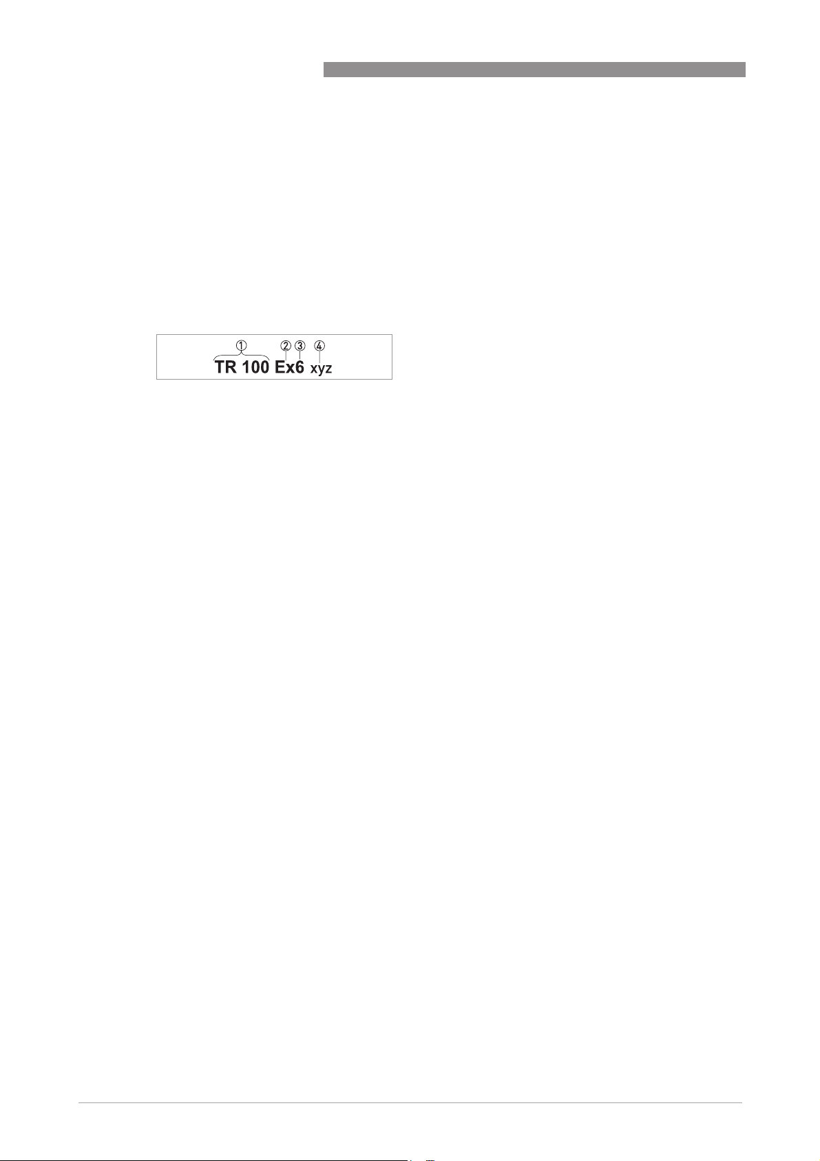
2.2 Description code
The safety description code of the measuring inserts is made up of the following elements
(spaces in the code may be omitted):
1 Sensor type (TR = resistance thermometer, TC = thermocouple)
2 Version (Ex = ATEX approved)
3 Diameter of measuring insert (6=6mm/ 0.24")
4 Space for information not relevant for ex purposes
The length of the measuring insert is displayed on the nameplate in plain text.
OPTITEMP TR/TC100
4
www.krohne.com 08/2010 - 4001022701 - Ex AD OPTITEMP TR/TC 100 R01
Page 5
OPTITEMP TR/TC100
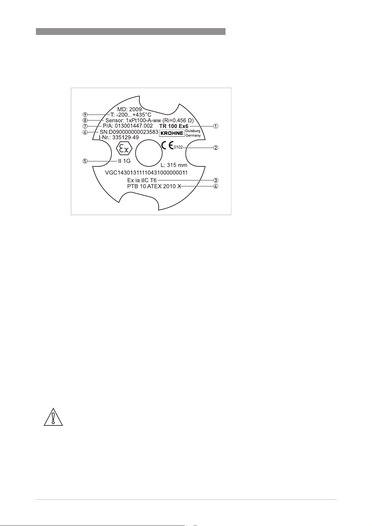
2.3 Marking
DEVICE DESCRIPTION 2
1 Description code
2 Identification number of the notified body as per Directive 94/95, Appendix IV
3 Ex-marking
4 Number of the EC Type Test Certificate
5 Equipment group and category
6 Unique serial number
7 Production order number
8 Sensor name (e.g. 1xPt100-A-ww): single/double version (here: simple, thus 1x), tolerance class (here: tolerance class
A), type of RTD (here: wire-wound version, thus ww)
9 Temperature range of use
2.4 Flammable products
Atmospheric conditions
An explosive atmosphere is a mixture of air and flammable gases, vapours, mists or dusts under
atmospheric conditions. The following values define it:
= -20...+60°C / -4...+140°Fand P
T
atm
Outside of this range, no key data are available as to ignition behaviour for most mixtures.
Operating conditions
Outside of atmospheric conditions you cannot apply explosion protection according to Directive
94/9/EC (ATEX) – regardless of the zone assignment - due to the lack of key safety data.
= 0.8...1.1 bar / 11.6...15.9 psi
atm
CAUTION!
The operator is responsible for ensuring that the measuring inserts are operated safely as
regards the temperature and pressure of the products used.
Include the thermometer assembly in the periodic pressure tests of the system when operating
with flammable products.
www.krohne.com08/2010 - 4001022701 - Ex AD OPTITEMP TR/TC 100 R01
5
Page 6

2 DEVICE DESCRIPTION
2.5 Equipment category
The measuring inserts are designed in category II 1 G for use in Zone 0.
INFORMATION!
Definition of Zone 0 according to EN 1127-1:
An area with a constant or long-term or frequent explosive atmosphere made up of a mixture of
flammable substances in the form of gas, vapours or mist.
OPTITEMP TR/TC100
For detailed information refer to
2.6 Protection types
The marking according to ATEX is: II 1G Ex ia IIC T6
The following types of protection are used:
• The measuring insert is designed in protection type intrinsically safe "i".
• Operation on intrinsically safe circuits with protection level "ia".
Flammable products
II 1G Ex ia IIC T6
II 1G Ex ia IIC T6II 1G Ex ia IIC T6
on page 5.
6
www.krohne.com 08/2010 - 4001022701 - Ex AD OPTITEMP TR/TC 100 R01
Page 7

OPTITEMP TR/TC100
2.7 Temperature classes
The permissible ambient temperature range of the measuring inserts at the terminal block is:
= -40°C...+100°C / -40°F...+212°F.
T
amb
Due to the influence of the product temperature, no fixed temperature class is assigned to
measuring inserts. The temperature class of the devices is much more a function of the existing
product temperature and the maximum value of the sensor output P
following tables for the assignment of the respective version.
CAUTION!
The maximum permissible product temperatures listed in the tables are valid under the
following conditions:
•
The measuring insert is installed and operated in accordance with the installation
instructions in the standard documentation.
•
Ensure that the measuring insert is not heated by the effects of additional heat radiation
(sunshine, neighbouring system components) and thus operated above the permissible
ambient temperature range.
DEVICE DESCRIPTION 2
. Please consult the
i
Maximum permissible product temperature in °C
Temperature
class
T1 450 436 432 425 402 391 383 380 365
T2 300 286 282 275 252 241 233 230 215
T3 200 191 187 180 157 146 138 135 120
T4 135 126 122 115 92 81 73 70 55
T5 100 91 87 80 57 46 - - -
T6 85 76 72 65 42 - - - -
T
o
Pi ≤
50mW
Pi ≤
100mW
Pi ≤
200mW
Maximum permissible product temperature in °F
Temperature
class
T1 842 816 809 797 755 735 721 716 689
T2 572 546 539 527 485 465 451 446 419
T3 392 375 368 356 314 294 280 275 248
T4 275 258 251 238 197 177 163 158 131
T5 212 195 188 176 134 114 - - -
T6 185 168 161 149 107 - - - -
T
o
Pi ≤
50 mW
Pi ≤
100 mW
Pi ≤
200 mW
Pi ≤
500mW
[°C]
Pi ≤
500 mW
[°F]
Pi ≤
650mW
Pi ≤
650 mW
Pi ≤
750mW
Pi ≤
750 mW
Pi ≤
800mW
Pi ≤
800 mW
Pi ≤
1000mW
Pi ≤
1000 mW
www.krohne.com08/2010 - 4001022701 - Ex AD OPTITEMP TR/TC 100 R01
7
Page 8

2 DEVICE DESCRIPTION
Regardless of the temperature class, the lower limit value for the product temperature for all
versions is:
OPTITEMP TR/TC100
• TC 100: T
• TR 100: T
2.8 Electrical data
Connect the sensor circuit of a measuring insert only to intrinsically safe circuits as well as
separate transmitters certified as intrinsically safe or zener barriers. Observe the following
maximum values:
=30V
• U
i
= 140 mA
• I
i
=1.0W
• P
i
Keep in mind the following maximum values for effective capacities and inductances when
interconnecting:
= -40°C / -40°F
M
= -200°C / -328°F
M
Sensor length
up to 5 m / 16.4 ft up to 30 m / 98.4 ft
Ci= [nF] L
TR100 with Pt100 wire wound 3.5 65 21 390
TC100 type K 2.5 25 14 150
TC100 type J 2 48.5 11.5 289.5
= [µH] C
i
= [nF] L
i
= [µH]
i
8
www.krohne.com 08/2010 - 4001022701 - Ex AD OPTITEMP TR/TC 100 R01
Page 9

OPTITEMP TR/TC100
3.1 Special Conditions
Operate the measuring insert only if it is installed in a connection head.
3.2 Installation
DANGER!
The manufacturer is not liable for any damage or injuries resulting from improper use or use
other than the intended purpose. This applies in particular to hazards due to insufficient
corrosion resistance and suitability of the materials in contact with product.
Installation and setup must be carried out according to the applicable installation standards (e.g.
EN 60079-14) by qualified personnel trained in explosion protection. Observe the information
contained in the manuals and the supplementary instructions.
Install the measuring inserts such that
• the terminal base is protected by a connection head,
• no external forces are acting on the measuring insert,
• the device is accessible for any necessary visual inspections and can be viewed from all sides.
INSTALLATION 3
www.krohne.com08/2010 - 4001022701 - Ex AD OPTITEMP TR/TC 100 R01
9
Page 10

4 ELECTRICAL CONNECTIONS
4.1 General notes
The actual temperature sensor, either a Pt100 RTD or a thermocouple, is located in the
replaceable measuring insert. It is inserted through the open head into the thermometer fitting
and attached with two spring loaded M4 screws.
Basic measuring insert versions
OPTITEMP TR/TC100
1 Measuring insert with terminal block
2 Measuring insert with flying wires for transmitter mounting
3 Measuring insert with Ex transmitter (separately approved)
DANGER!
The Ex manual for the transmitter also applies to the variant with the Ex transmitter!
10
www.krohne.com 08/2010 - 4001022701 - Ex AD OPTITEMP TR/TC 100 R01
Page 11

OPTITEMP TR/TC100
4.2 Power supply
As required for further information about the power supply to the measuring inserts refer to
Electrical data
DANGER!
If you are operating the measuring insert together with a transmitter, pay attention to the details
about the power supply in the Ex documentation of the transmitter used. Also observe the
maximum values of the sensor circuit.
on page 8.
4.3 Inputs / Outputs
4.3.1 Pt100 measuring inserts
A measuring insert with a Pt RTD is connected according to DIN EN 60751 in three different
wiring variants (from left to right: 2, 3 and 4 wire switch):
TR 100: Wiring (simple design)
ELECTRICAL CONNECTIONS 4
1 white
2 red
www.krohne.com08/2010 - 4001022701 - Ex AD OPTITEMP TR/TC 100 R01
11
Page 12

4 ELECTRICAL CONNECTIONS
4.3.2 Thermocouple measuring inserts
Wiring of a thermocouple measuring insert is done in accordance with DIN EN 60584:
TC 100: Wiring (simple design)
4.4 Earthing and equipotential bonding
The measuring insert connections withstand a test voltage of 500 VAC to earth.
OPTITEMP TR/TC100
DANGER!
Equipotential bonding
Equipotential bonding
Equipotential bondingEquipotential bonding
Always include the measuring inserts in the equipotential bonding of the installation site (when
installed correctly, the fixing screws guarantee this).
12
www.krohne.com 08/2010 - 4001022701 - Ex AD OPTITEMP TR/TC 100 R01
Page 13

OPTITEMP TR/TC100
5.1 Start-up
DANGER!
To avoid injury and material damage, only operate the measuring inserts under the following
conditions:
•
The equipment was installed and connected in accordance with the manufacturer's
instructions.
•
At the operator's request, a test was conducted prior to start-up to ensure the correct
installation and connection.
•
The check prior to start-up was in compliance with the national regulations for checks before
start-up.
5.2 Operation
DANGER!
To avoid injury and material damage, only operate the measuring inserts under the following
conditions:
OPERATION 5
•
Temperatures, pressures and electrical limit values are in the manufacturer's specified
range.
•
The equipment parts necessary for safety are effective in the long run, never disable them
during operation!
www.krohne.com08/2010 - 4001022701 - Ex AD OPTITEMP TR/TC 100 R01
13
Page 14

6 SERVICE
6.1 Maintenance
DANGER!
Maintenance measures of a safety-relevant nature within the meaning of explosion protection
may only be carried out by the manufacturer, his authorised representative or under the
supervision of authorised inspectors.
For systems in hazardous areas, regular tests are required in order to maintain the proper
condition. The manufacturer recommends checking the following components regularly for
corrosion and damage:
• Housing
• Cable entry(ies)
• Feed lines
6.2 Dismantling
DANGER!
To avoid injury and material damage caused by electric shock, only remove the measuring insert
in a de-energised state!
OPTITEMP TR/TC100
CAUTION!
So as not to damage the cover of the connection head, only open it using a suitable tool (e.g. a
screwdriver).
INFORMATION!
You can replace the measuring insert with a measuring insert identical in construction.
14
www.krohne.com 08/2010 - 4001022701 - Ex AD OPTITEMP TR/TC 100 R01
Page 15

OPTITEMP TR/TC100
NOTES 7
www.krohne.com08/2010 - 4001022701 - Ex AD OPTITEMP TR/TC 100 R01
15
Page 16

KROHNE product overview
• Electromagnetic flowmeters
• Variable area flowmeters
• Ultrasonic flowmeters
• Mass flowmeters
• Vortex flowmeters
• Flow controllers
• Level meters
• Temperature meters
• Pressure meters
• Analysis products
• Measuring systems for the oil and gas industry
• Measuring systems for sea-going tankers
Head Office KROHNE Messtechnik GmbH
Ludwig-Krohne-Str. 5
D-47058 Duisburg (Germany)
Tel.:+49 (0)203 301 0
Fax:+49 (0)203 301 10389
info@krohne.de
© KROHNE 08/2010 - 4001022701 - Ex AD OPTITEMP TR/TC 100 R01 en - Subject to change without notice.
The current list of all KROHNE contacts and addresses can be found at:
www.krohne.com
 Loading...