

Page 1
Data sheet
Liquid Level Switch
Type LLS 4000/4000U
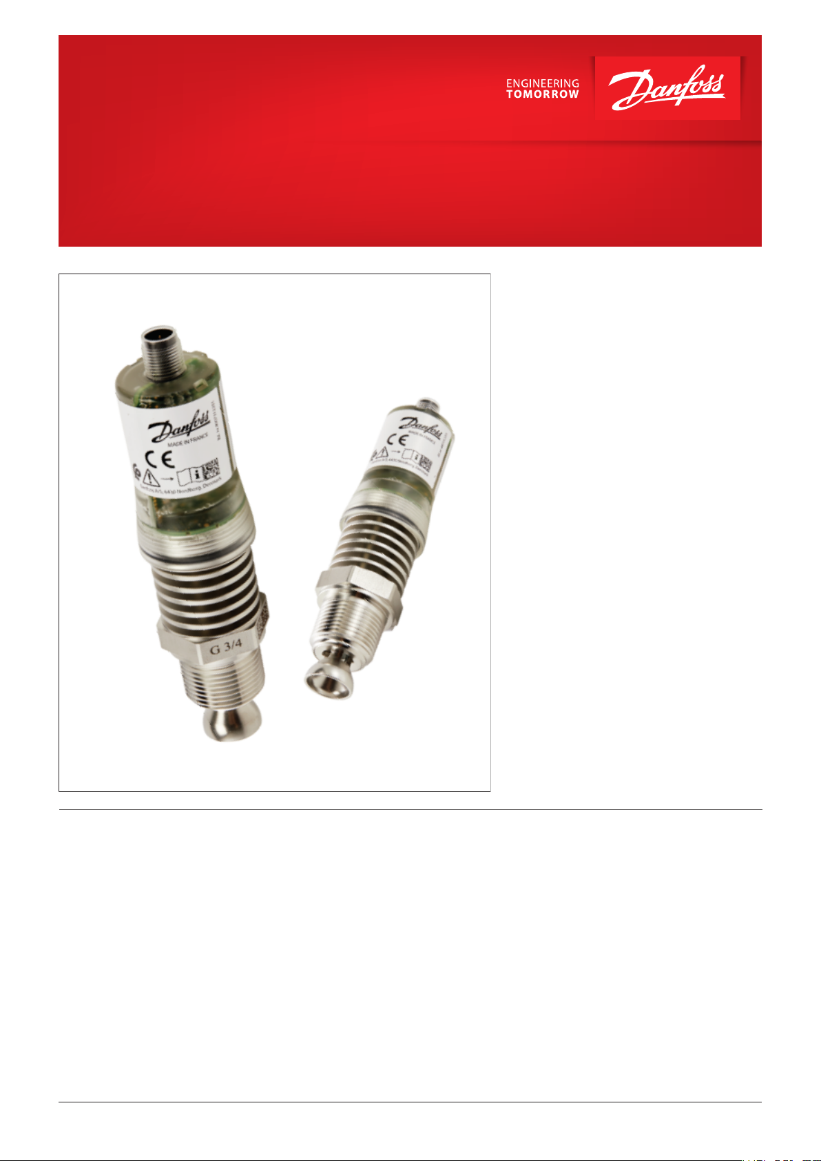
The LLS 4000/4000U liquid level switch is
designed to detect the state (gas or liquid) of the
refrigerant in front of the sensing head, while
installed in a wide range of refrigeration
applications.
The LLS level switch comes in 2 variants, LLS 4000
and LLS 4000U. They are identical except for the
connector thread interface to the system. The LLS
4000 is provided with G3/4" thread, while the LLS
4000U is provided with NPT 3/4" thread.
The LLS 4000/4000U liquid level switch is based
on the proven reflectometry measuring
technology(microwave level measurement)
adapted specifically for the new LLS 4000/4000U
switch.
LLS 4000/4000U liquid level switches can be used
to control the liquid level of many different
refrigerants in vessels, accumulators, receivers,
standpipes, etc.
The switches are normally installed in a pair of
two, controlling the upper liquid level and the
lower liquid level.
The level switch includes a relay that switches by
change in refrigerant state. The on site
configuration of the LLS allows the normally
open/closed relay setting depending on the
desired correlation.
Features
• Plug and play liquid level switch
• Easy installation and minimum or no need for
configuration
• Convenient communication with all units via
Bluetooth and a Danfoss app
• SIL2 compliant version
• 2 commonly used connection variants
• Maintenance free
• Replacement of electronic part without
removing mechanical part (no opening to
refrigerant)
• Applicable for ammonia and commonly used
H(C)FCs
• Well proven reflectometry measuring principle
For SIL applications a SIL2 version is available
with blocked configuration (not configurable).
All configuration and readings from the LLS
switch are performed through Bluetooth and a
downloadable special Danfoss app.
• Approvals: CE, PED, EMC, RED, ROHS, SIL2, FCC,
( EAC, IC pending)
• Conforms to:
Telecommunications Directive RED 2014/53/EU.
Low voltage directive 2014/35/EU.
EMC directive 2014/30/EU.
ROHS 2011/65/EU
© Danfoss | DCS (ms) | 2020.02
AI323832972563en-000101 | 1
Page 2
Contents
Data sheet | Liquid Level Switch, type LLS 4000/4000U
Features .............................................................................. 1
uct concept/applications ........................................................... 3
Prod
Connection types ...................................................................... 4
Measuring principle..................................................................... 4
e
ctrical installation/connection......................................................... 5
El
LED light indicators .................................................................... 5
Configurable parameters .... .. ..... .. ..... ... ..
Ordering ................
Dimensions and weights .................................................................7
Maintenance/service & calibration precautions............... ............................. 8
Bluetooth communication .............................................................. 8
Bluetooth configuration ................................................................ 9
Technical data .................................
Safety/ Approvals .......................................................................11
.. ... ..... ... .. .. ... ..... .. ... . 5
..... ... .... .. .... ... ..... ... .... ... ..... .. ..... .. ... 7
........................................10
2 | AI323832972563en-000101
© Danfoss | DCS (ms) | 2020.02
Page 3
Product concept/
Data sheet | Liquid Level Switch, type LLS 4000/4000U
applications
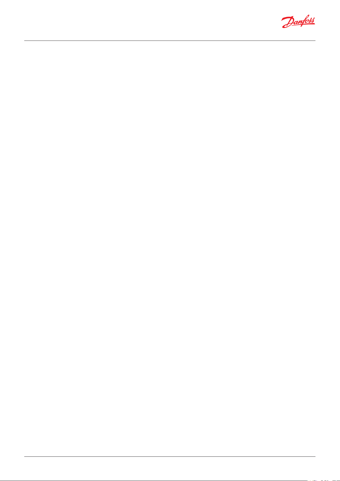
To control if a liquid level is within predened
allowed limits, two LLS 4000 are installed in an
upper and a lower limit position respectively. By
this setup the liquid level is between the two
level switches and the lower switch will sense
liquid, while the upper will sense gas.
In case the liquid level moves outside the limits,
one of the switches will sense opposite and
switch the built-in relay. This relay switch function
should be used for alarm settings. This is made
easy when connected to the system PLC.
SFA
+DSV
FIA
SNV
SCA-X
SVA
SNV
RT
260A
SNV
SVA
BSV
LLG
LLS 4000
LLS 4000
SVA
SVA
AKS 4100
LLG
SCA-X
SNV
SVA
SVA
260A
EKE
347
ICF 25-6-5A
SVA
SNV
SVA
BSV
SNV
SVA
QDV
15
FIA
SNV
RT
SNV
The LLS can be used wherever liquid levels of
ammonia and certain H(C)FC refrigerants must
be controlled.
Upper
LLS 4000/U
Lower
LLS 4000/U
The LLS comes in 2 versions:
- A standard version, which is applicable for most
refrigeration or processing plants, and is fully
configurable regarding type of liquid and relay
setting.
- A SIL2 version applicable for SIL compliant
process plants. This version is non-configurable
regarding relay setting (see section: Configurable
parameters) and is intended specific as the upper
level switch.
Liq. Level
© Danfoss | DCS (ms) | 2020.02
AI323832972563en-000101 | 3
Page 4
Data sheet | Liquid Level Switch, type LLS 4000/4000U
Connection types
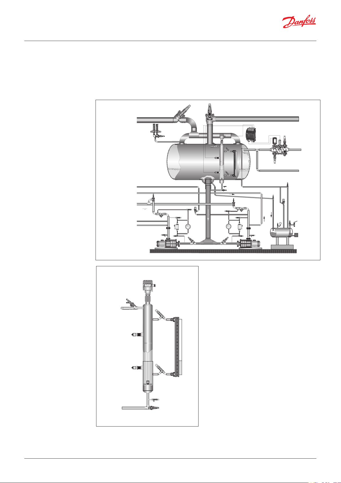
Beside the 2 versions the LLS also comes with 2
different thread types , LLS 4000 and LLS 4000U.
They are identical except for the connector
thread for installation to the system. The LLS
4000 is provided with G¾" thread, while the LLS
4000U is provided with NPT ¾" thread.
LLS 4000
LLS 4000U
G ¾”
NPT ¾”
For connection to the actual part of the system
appropriate weld connectors are needed. NPT
connectors are widespread available, while
Danfoss offers weld connectors for G3/4" thread
as accessory.
Please note geometric restrictions below.
Weld
connector
max
45 mm
1.8 in
min
25 mm
1 in
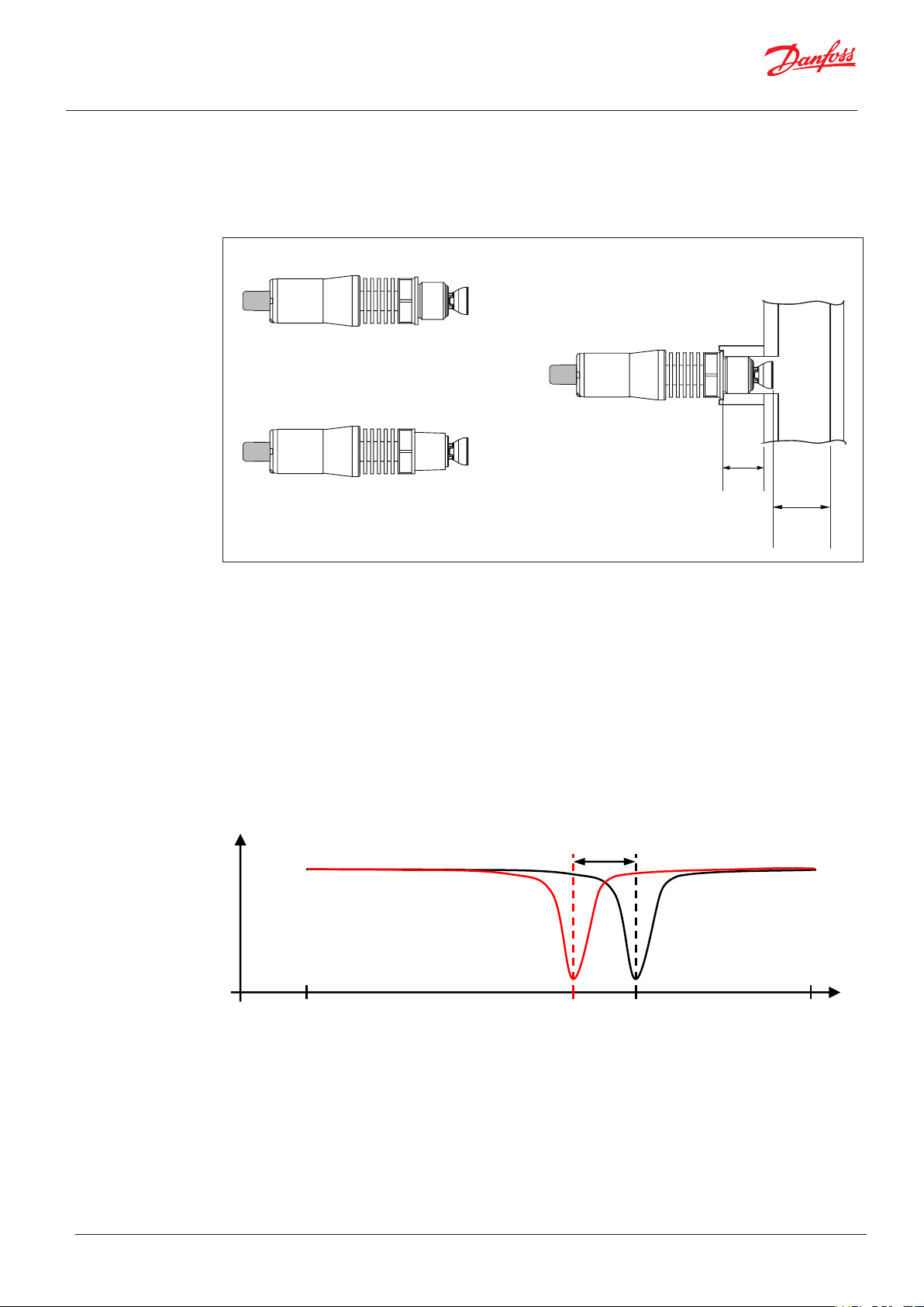
Measuring principle
The measurement principle of the LLS is based
on reflectometry with a 4.9 GHz to 6.2 GHz
linear sweep (Microwave switch technology).
The reflected signal is characterized by a
resonance frequency. The resonance frequency
in air is taken as a reference (fref). When the
sensing element is in contact with the liquid,
the resonance frequency is shifting to a lower
frequency. This is due to the change of the
dielectric constant of the medium.
P
R
4.9 GHz 6,2GHz
with
liquid
The point level switch monitors the resonance
frequency and indicates whether the sensing
element is surrounded by liquid or gas.
The figure below shows the reference frequency
with air (dielectric constant εr=1) in front of the
sensing element and with a liquid dielectric
constant εr> 1.35.
∆f ~ ε
r
without
liquid
f
liquid
f
ref
f
© Danfoss | DCS (ms) | 2020.02
AI323832972563en-000101 | 4
Page 5

Data sheet | Liquid Level Switch, type LLS 4000/4000U
1
2
3
4
+ Red
- White
Green
Black
Relay: 30 V DC
200 mA
24 V DC
+/- 25%
Electrical installation/
connection
The LLS 4000 level switch must be installed as
one unit (mechanical and electrical assembled)
without disassembly to avoid the need for
recalibration.
For powering the device, a low power source
(LPS) must be used with safety extra low
voltage output (SELV) and current limited to 8A
maximum
After connecting the M12 female cable to the
power supply and relay circuit the M12 plug can
be installed on the M12 male connector and the
power can be switched on.
At this stage the green light LED will turn on and
be visible through the transparent housing.
The LLS is now ready for configuration via the
Danfoss Bluetooth app (see section: Configurable
parameters).
Danfoss M12 cables (ordered separately)
M12 cable female x 2 meter
M12 cable female x 8 meter
1
2
4
3
LED light indicators
Configurable parameters
Red light LED
Yellow light LED
Green light LED
There are 3 LED indicators inside the LLS 4000
behind the transparent cover.
• Green indicates the state of power to the
switch.
If flashing: Bluetooth connection is
established
• Yellow indicates if liquid is in front of switch.
• Red indicates if alarm is present.
The set-up of the LLS 4000 is easy and simple,
since only few parameters in the LLS software are
configurable. These are:
Green
Black
Relay: 30 V DC
200 mA
- White
24 V DC
+/- 25%
+ Red
For plants where factory defaults are valid, the
installation and set-up is simply Plug & play.
| AI323832972563en-000101
5
• Media type - Ammonia or Freon (H(C)FC).
Factory default: Ammonia
• Relay NO (normally open) or NC (normally
closed)
Factory default: Normally closed
Below table shows possible configurations, relay
state for given configuration/liquid level and LED
indications
© Danfoss | DCS (ms) | 2020.02
Page 6

Data sheet | Liquid Level Switch, type LLS 4000/4000U
High Level
sensor
High Level
sensor
Low Level
sensor
Low Level
sensor
Level
LLS
4000/4000U
NO mode*
LLS
4000/4000U
NC mode*
SIL2 fixed
configura
tion
Voltage
connected
Green LED Yellow LED Red LED
Level
detection
LLS Fault
Voltage
supply
outside
spec.
LLS
4000/4000U
fault**
* Configuration dependent. Non-SIL2 fully configurable. SIL2 fixed configuration and only applicable
for High Level sensor
** For complete list of failure types refer to failure type section
*** Fault can be detected at any detected level, ie. 2 or all 3 lights on
–
***
–
© Danfoss | DCS (ms) | 2020.02
AI323832972563en-000101 | 6
Page 7

Data sheet | Liquid Level Switch, type LLS 4000/4000U
Ordering
LLS 4000/4000U
Description Code Number
LLS 4000 liquid level switch (excl. welding connector & M12 cable) G 3/4"
LLS 4000 SIL2 liquid level switch (excl. welding connector & M12 cable) G 3/4"
LLS 4000U liquid level switch (excl. welding connector & M12 cable) NPT 3/4"
LLS 4000U SIL2 liquid level switch (excl. welding connector & M12 cable) NPT 3/4"
Spare parts/Accessories
Description Code Number
Weld connector 3/4”G
LLS 4000/U Electronic top part, non SIL2
M12 Danfoss female cable, 2 meter (6.6 ft) 034G7073
M12 Danfoss female cable, 8 meter (26.2 ft) 034G7074
LLS 4000/U Inspection sealing kit
84H6001
0
84H6002
0
0
84H6003
84H6004
0
084H6012
084H601
0
84H6011
0
Dimensions and weights
LLS 4000
19,5
LLS 4000U
0.6
20 15
G3/4
34
H32
142,4
(mm)
5.6
71,3 2
M12x1
36
Weight: approx. 350 g / 0.77 lbs
2.80.78
7 | AI323832972563en-000101
0.77
3/4 NPT
H32
(in)
M12x1
1.4
Weight: approx. 350 g / 0.77 lbs
© Danfoss | DCS (ms) | 2020.02
Page 8

Maintenance/service &
Data sheet | Liquid Level Switch, type LLS 4000/4000U
calibration precautions
The LLS 4000 is considered maintenance free,
but there are a few precautions that needs
attention.
The fins shall be kept free of dirt, dust, paint
and oil etc. that potentially reduces the
thermal heat transfer from the fins to the air.
Ice build-up on the LLS switch reduces the
accessibility for the Bluetooth connection.
- 10 cm icecap reduces the distance from
app device to the LLS to 1 meter.
- 20 cm icecap is considered as the
maximum to be able to connect.
For LLS cleaning use soft cloth dry or wet or
compressed air.
If the electronic part is separated from the
mechanical part during installation, service or
maintenance, the ingress of any foreign
substances to the electronic or mechanical
part shall be avoided.
Generally the separating of electronic and
mechanical parts should be avoided due to
calibration, and the mixing of mechanical and
electronic parts from different switches must
be avoided. In case of the incident mixing of
mechanical and electronic parts from different
switches, subsequent recalibration might be
required.
Prior to calibration the following must be
ensured:
The LLS must be out of liquid state (in gas
phase), otherwise the calibration might end
up incorrect.
This can be secured by either emptying the
actual vessel or uninstall the LLS to ambient
air.
While in "dry" surroundings, connect power to
the LLS switch and perform the calibration.
Ice as such do not impact the functionality
of the product as far as the minimum
ambient temperature is respected.
Bluetooth
communication
The danfoss LLS app includes the calibration
possibility.
- A special Danfoss LLS app can be
downloaded from Android google play or IOS
app store.
- All communication with all LLS installed in a
plant is done by use of this app.
Communication can only happen with one
LLS at a time.
- Each LLS switch includes its own serial
number, which will appear in the app when
connected. At the same time the green light
LED in the actual connected LLS will be
flashing.
Bluetooth® word mark and logos are
registered trademarks of Bluetooth SIG Inc.
Android and Google Play are registered
trademark of Google LLC. App Store is
registered trademarks of Apple Inc.
© Danfoss | DCS (ms) | 2020.02
AI323832972563en-000101 | 8
Page 9

Data sheet | Liquid Level Switch, type LLS 4000/4000U
Bluetooth
configuration
The first time parameter setting of an
individual LLS switch is done by opening
of the app and performing a scan for
devices. The app will get a list of LLS that
are present at the actual location.
will include a name and the matching
serial number for each of the present LLS.
1.
Choose the first item on the list and
observe which LLS' green LED is
flashing.
2.
Log-in with the provided PIN code.
(For safety reason the PIN code should
be changed afterwards).
3.
Touch the Menu Icon.
4.
Touch the Log-in.
5.
Enter the Password provided.
6.
Rename the device to an up to 24
symbol name (8 symbols visible).
7.
Check the parameter settings and if
needed change one or both parameters
Media type/ Switch state.
8.
Note the ID: Name, serial number, media
type and switch state.
9.
Close the app and observe that the
green light stops flashing.
10. This LLS is now ready for operation.
11.
If more LLS are present choose the next
item on the list and repeat steps 1 to 10.
The list
The name and configurable parameters
of any LLS can be changed at any time.
© Danfoss | DCS (ms) | 2020.02
AI323832972563en-000101 | 9
Page 10

Data sheet | Liquid Level Switch, type LLS 4000/4000U
Technical data
© Danfoss | DCS (ms) | 2020.02
AI323832972563en-000101 | 10
Page 11

Data sheet | Liquid Level Switch, type LLS 4000/4000U
Safety/
Approvals
Warning! This is a Class A device.
This device may cause radio
interference in residential areas.
In case o
may be required to take
appropriate measures.
This instrument has to be mounted
on a metallic tank.
The device is intended to be used in
industrial areas.
f interference, the operator
General Warnings/precautions
- Every use that is not described in this
data sheet is considered incorrect and is
not authorized by the manufacturer.
- The LLS device should only be used with
approved media listed under Technical
data. Use with other media must be
validated by Danfoss before installation.
- Verify that the installation and operating
conditions of the device respect those
specified in this sheet, especially concerning
the supply voltage and environmental
conditions.
- All service and maintenance operations
must be performed by qualified personnel.
- Installation must comply with local
standards and legislation.
- Before carrying out any maintenance
operations on the device, disconnect the
device from the main power supply.
- Before unscrewing the LLS device from the
pipe or tank ensure that pipe or tank is
empty and not under pressure.
- Liability for injury or damage caused by
incorrect use of the device lies solely with
the user.
- Depending on the application, the metallic
part of the instrument may be hot or cold.
- If media detection or non-detection by
the level switch could generate a hazard
the SIL version and specific instructions
described in the safety manual (periodic
proof test) should be used. The SIL safety
manual can be downloaded from the
Danfoss web site.
USA/Canada:
This device complies with Part 15 of the
FCC Rules and with RSS-210 of Industry
Canada. Operation is subject to the
following two conditions. (1) this device
may not cause harmful interference, and
(2) this device must accept any
interference received, including
interference that may cause undesired
operation. Changes or modifications not
expressly approved by the party
responsible for compliance could void the
user's authority to operate the equipment.
This device complies with FCC and ISED RF
radiation exposure limits set forth for
general population. This device must be
installed to provide a separation distance
of at least 20cm from all persons and must
not be co-located or operating in
conjunction with any other antenna or
transmitter.
The Product Marketing name of the
instrument is ‘LLS 4000 series’.
Read and apply safety instructions contained in product documentation.
Contact : Danfoss A/S, 6430 Nordborg, Denmark
© Danfoss | DCS (ms) | 2020.02
AI323832972563en-000101 | 11
 Loading...