

Page 1

OPTISENS PAS 2000
OPTISENS PAS 2000
OPTISENS PAS 2000OPTISENS PAS 2000
pH and ORP sensors
Handbook
Handbook
HandbookHandbook
Page 2

: IMPRINT
:::::::::::::::::::::::::::::::::::::::::::::::::::::
OPTISENS PAS 2000
All rights reserved. It is prohibited to reproduce this documentation, or any part thereof, without
the prior written authorisation of KROHNE Messtechnik GmbH & Co. KG.
Subject to change without notice.
Copyright 2008 by KROHNE Messtechnik GmbH & Co.KG - Ludwig-Krohne-Straße 5 - 47058
Duisburg
2
www.krohne.com 11/2008 • MA PAS 2000 R04 en
Page 3

OPTISENS PAS 2000
1 Safety instructions......................................................................... 5
1.1 Intended use......................................................................................................... 5
1.2 Safety instructions from the manufacturer......................................................... 5
1.2.1 Copyright and data protection................................................................................... 5
1.2.2 Disclaimer.................................................................................................................. 5
1.2.3 Product liability and warranty ...................................................................................6
1.2.4 Information concerning the documentation .............................................................6
1.2.5 Display conventions................................................................................................... 7
1.3 Safety instructions for the operator .................................................................... 7
2 Device description ......................................................................... 8
2.1 Scope of delivery .................................................................................................. 8
2.2 Device description................................................................................................ 9
2.3 Nameplates........................................................................................................ 10
2.3.1 OPTISENS PAS 2000 pH sensor .............................................................................. 10
2.3.2 OPTISENS PAS 2000 ORP sensor............................................................................ 11
CONTENTS
3 Installation................................................................................... 12
3.1 Notes on installation.......................................................................................... 12
3.2 Storage & Transport .......................................................................................... 12
3.3 Installing the sensor .......................................................................................... 13
3.3.1 Basic installation instructions................................................................................. 13
3.3.2 Mounting to MAA 2000 telescopic rod immersion holder ...................................... 13
3.3.3 MAA 2000 sensor holder and telescopic rod...........................................................16
3.3.4 Assembly of PAS 2000 to MAA 2000 slide rail immersion holder .......................... 17
3.3.5 Cable connections ................................................................................................... 18
3.4 Mounting the electrode...................................................................................... 18
4 Electrical connections ................................................................. 20
4.1 Safety instructions ............................................................................................. 20
4.2 Cable connections.............................................................................................. 20
5 Operation ..................................................................................... 21
5.1 Sensor display.................................................................................................... 21
5.2 Menu for sensors ............................................................................................... 21
5.2.1 Menu for PAS 2000 pH............................................................................................. 21
5.2.2 Menu for PAS 2000 ORP ..........................................................................................23
5.3 Calibration.......................................................................................................... 24
5.3.1 Calibrating pH.......................................................................................................... 25
5.3.2 Adjusting ORP..........................................................................................................26
5.4 Scaling................................................................................................................ 26
6 Service......................................................................................... 27
6.1 Maintenance....................................................................................................... 27
6.1.1 Broken electrode..................................................................................................... 27
www.krohne.com11/2008 • MA PAS 2000 R04 en
3
Page 4

CONTENTS
6.1.2 Error messages .......................................................................................................27
6.1.3 Incorrect measurements......................................................................................... 28
6.1.4 Cleaning of the flushing nozzle ............................................................................... 28
6.2 Cleaning ............................................................................................................. 28
6.3 Spare parts availability ...................................................................................... 30
6.4 Availability of services........................................................................................ 30
6.5 Returning the device to the manufacturer ........................................................ 31
6.5.1 General information ................................................................................................ 31
6.5.2 Form (for copying) to accompany a returned device .............................................. 32
6.6 Disposal.............................................................................................................. 32
7 Technical data ............................................................................. 33
7.1 Measuring principle ........................................................................................... 33
7.2 Data table ........................................................................................................... 34
7.3 Dimensions & Weight......................................................................................... 36
OPTISENS PAS 2000
8 Appendix...................................................................................... 38
8.1 pH as a function of mV ....................................................................................... 38
8.2 pH temperature dependency ............................................................................. 39
8.3 Support information form.................................................................................. 40
8.4 Setup information form ..................................................................................... 41
9 KROHNE measuring technology - Product overview................... 44
4
www.krohne.com 11/2008 • MA PAS 2000 R04 en
Page 5

OPTISENS PAS 2000
1.1 Intended use
The OPTISENS PAS 2000 Sensors are used to measure pH value or ORP potential in water and
wastewater treatment plants and other industrial applications.
1.2 Safety instructions from the manufacturer
1.2.1 Copyright and data protection
The contents of this document have been created with great care. Nevertheless, we provide no
guarantee that the contents are correct, complete or up-to-date.
The contents and works in this document are subject to German copyright. Contributions from
third parties are identified as such. Reproduction, processing, dissemination and any type of use
beyond what is permitted under copyright requires written authorisation from the respective
author and/or the manufacturer.
SAFETY INSTRUCTIONS 1
The manufacturer tries always to observe the copyrights of others, and to draw on works created
in-house or works in the public domain.
The collection of personal data (such as names, street addresses or e-mail addresses) in the
manufacturer's documents is always on a voluntary basis whenever possible. Whenever
feasible, it is always possible to make use of the offerings and services without providing any
personal data.
We draw your attention to the fact that data transmission over the Internet (e.g. when
communicating by e-mail) may involve gaps in security. It is not possible to protect such data
completely against access by third parties.
We hereby expressly prohibit the use of the contact data published as part of our duty to publish
an imprint for the purpose of sending us any advertising or informational materials that we have
not expressly requested.
1.2.2 Disclaimer
The manufacturer will not be liable for any damage of any kind by using its product, including,
but not limited to direct, indirect, incidental, punitive and consequential damages.
This disclaimer does not apply in case the manufacturer has acted on purpose or with gross
negligence. In the event any applicable law does not allow such limitations on implied warranties
or the exclusion of limitation of certain damages, you may, if such law applies to you, not be
subject to some or all of the above disclaimer, exclusions or limitations.
www.krohne.com11/2008 • MA PAS 2000 R04 en
5
Page 6

1 SAFETY INSTRUCTIONS
Any product purchased from the manufacturer is warranted in accordance with the relevant
product documentation and our Terms and Conditions of Sale.
The manufacturer reserves the right to alter the content of its documents, including this
disclaimer in any way, at any time, for any reason, without prior notification, and will not be liable
in any way for possible consequences of such changes.
1.2.3 Product liability and warranty
The operator shall bear responsibility for the suitability of the device for the specific purpose.
The manufacturer accepts no liability for the consequences of misuse by the operator. Improper
installation and operation of the devices (systems) will cause the warranty to be void. The
respective "Standard Terms and Conditions" which form the basis for the sales contract shall
also apply.
OPTISENS PAS 2000
1.2.4 Information concerning the documentation
To prevent any injury to the user or damage to the device it is essential that you read the
information in this document and observe applicable national standards, safety requirements
and accident prevention regulations.
If this document is not in your native language and if you have any problems understanding the
text, we advise you to contact your local office for assistance. The manufacturer can not accept
responsibility for any damage or injury caused by misunderstanding of the information in this
document.
This document is provided to help you establish operating conditions, which will permit safe and
efficient use of this device. Special considerations and precautions are also described in the
document, which appear in the form of underneath icons.
6
www.krohne.com 11/2008 • MA PAS 2000 R04 en
Page 7
OPTISENS PAS 2000
1.2.5 Display conventions
The following symbols are used to help you navigate this documentation more easily:
DANGER!
This symbol designates safety advice on handling electricity.
WARNING!
These warning signs must be observed without fail. Even only partial disregarding such
warnings can result in serious health damage, damage to the device itself or to parts of the
operator
CAUTION!
These warnings must be observed without fail. Even only partial disregarding such warnings can
lead to improper functioning of the device.
’
s plant.
SAFETY INSTRUCTIONS 1
LEGAL NOTICE!
This symbol designates information on statutory directives and standards.
NOTE!
This symbol designates important information for the handling of the device.
• HANDLING
HANDLING
HANDLINGHANDLING
This symbol designates all instructions for actions to be carried out by the operator in the
specified sequence.
i CONSEQUENCE
CONSEQUENCE
CONSEQUENCECONSEQUENCE
This symbol designates all important consequences of the previous actions.
1.3 Safety instructions for the operator
WARNING!
In general, devices from the manufacturer may only be installed, commissioned, operated and
maintained by properly trained and authorized personnel.
This document is provided to help you establish operating conditions, which will permit safe and
efficient use of this device.
www.krohne.com11/2008 • MA PAS 2000 R04 en
7
Page 8
2 DEVICE DESCRIPTION
2.1 Scope of delivery
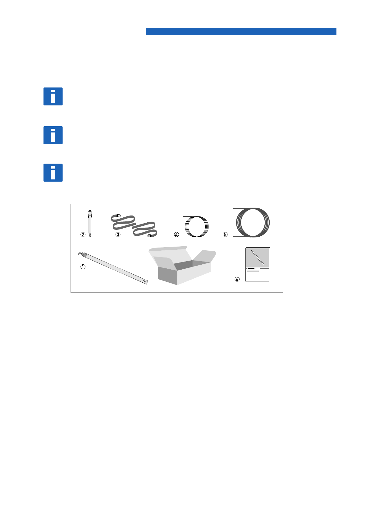
INFORMATION!
Inspect the cartons carefully for damage or signs of rough handling. Report damage to the
carrier and to the local office of the manufacturer.
INFORMATION!
Check the packing list to check if you received completely all that you ordered.
INFORMATION!
Look at the device nameplate to ensure that the device is delivered according to your order.
Check for the correct supply voltage printed on the nameplate.
OPTISENS PAS 2000
Figure 2-1: Standard scope of delivery for PAS 2000 pH sensor
1 PAS 2000 pH sensor
2 Gel-filled pH combination electrode
3 2 straps
4 10 m / 33 ft cable
5 10 m / 33 ft flush hose
6 Complete documentation
8
www.krohne.com 11/2008 • MA PAS 2000 R04 en
Page 9

OPTISENS PAS 2000
Figure 2-2: Standard scope of delivery for PAS 2000 ORP sensor
1 PAS 2000 ORP sensor
2 Gel-filled ORP combination electrode
3 2 straps
4 10 m / 33 ft cable
5 10 m / 33 ft flush hose
6 Complete documentation
DEVICE DESCRIPTION 2
Accessories available for PAS 2000 sensors
• MAA 2000 Insertion Holder, Telescopic Rod for PAS 2000 (inclusive telescopic rod plus rod
holder, handrail mounting bracket, sensor adapter)
• MAA 2000 Side Wall Mounting for PAS 2000
• Signal cable extension for OPTISENS 2000 sensors, 10 m / 33 ft
• Signal cable extension for OPTISENS 2000 sensors, 10 m / 33 ft
Consumables/Spare parts available for PAS 2000 sensors
• pH - electrode PAS 2000 pH
• ORP- electrode PAS 2000 ORP
2.2 Device description
INFORMATION!
This manual details installation procedures and operational features of the KROHNE
OPTISENS 2000 pH and ORP sensors. Menu navigation and technical data for the MAC 080
converter can be found in the OPTISENS MAC 080 manual.
The PAS 2000 sensors are manufactured in SIS2343 (316SS) stainless steel and PVC. The
sensors are mounted onto the MAA 2000 Adjustable telescopic rod holder using a POM adapter.
An adjustable stainless steel slide rail holder is available as an option. All PAS 2000 sensors
incorporate automatic cleaning as standard. The electronics is protected in the rugged casing,
ensuring its reliability in very demanding environments.
www.krohne.com11/2008 • MA PAS 2000 R04 en
9
Page 10

2 DEVICE DESCRIPTION
The sensor has a fixed, shielded 10 m / 33 ft cable used for signal transmission between the
sensor and the MAC 080 converter. The cable sheath is made of Hytrel and is highly resistant to
aggressive materials and fluids.
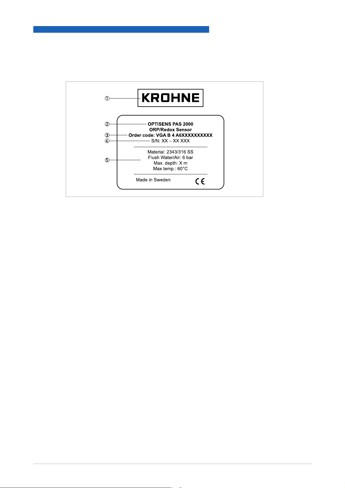
2.3 Nameplates
INFORMATION!
Look at the device nameplate to ensure that the device is delivered according to your order.
Check for the correct supply voltage printed on the nameplate.
2.3.1 OPTISENS PAS 2000 pH sensor
OPTISENS PAS 2000
Figure 2-3: Nameplate OPTISENS PAS 2000 ph sensor
1 Manufacturer
2 Device type
3 Order code
4 Serial number
5 Sensor information
10
www.krohne.com 11/2008 • MA PAS 2000 R04 en
Page 11
OPTISENS PAS 2000
2.3.2 OPTISENS PAS 2000 ORP sensor
DEVICE DESCRIPTION 2
Figure 2-4: Nameplate OPTISENS PAS 2000 ORP
1 Manufacturer
2 Device type
3 Order code
4 Serial number
5 Sensor information
www.krohne.com11/2008 • MA PAS 2000 R04 en
11
Page 12

3 INSTALLATION
3.1 Notes on installation
INFORMATION!
Inspect the cartons carefully for damage or signs of rough handling. Report damage to the
carrier and to the local office of the manufacturer.
INFORMATION!
Check the packing list to check if you received completely all that you ordered.
INFORMATION!
Look at the device nameplate to ensure that the device is delivered according to your order.
Check for the correct supply voltage printed on the nameplate.
3.2 Storage & Transport
OPTISENS PAS 2000
• Store the device in a dry, dust-free location.
• Avoid continuous direct sunlight.
• The original packaging is designed to protect the equipment. It has to be used if you the
device is transported or send back to the manufacturer.
12
www.krohne.com 11/2008 • MA PAS 2000 R04 en
Page 13
OPTISENS PAS 2000
3.3 Installing the sensor
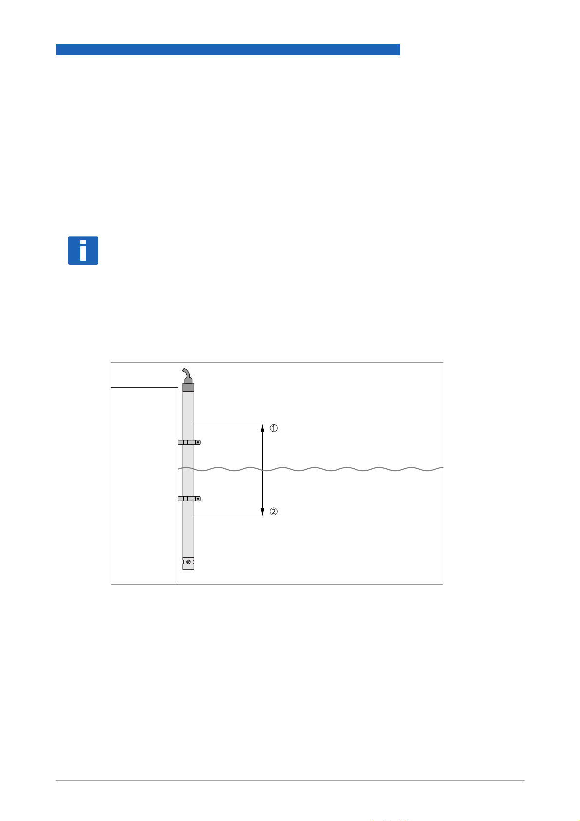
3.3.1 Basic installation instructions
The electrode should be placed deep enough so that it always stays in the measuring media,
even when the level varies (see figure 3-1). The measuring ability of the electrode is influenced
negatively if the column of liquid to be measured is too large. For optimal results the column
should not exceed 300 mm / 12".
NOTE!
To protect the sensor from damage, the sensor should never be fully submerged into water.
Therefore a maximal immersion depth of 800 mm / 31" has to be maintained.
The sensor should be mounted in a vertical position. In some applications it may be desirable to
mount at a certain angle. In this case the angle from the horizontal plane should be greater than
or equal to 45°.
INSTALLATION 3
Figure 3-1: Installing the PAS 2000 in a flume
3.3.2 Mounting to MAA 2000 telescopic rod immersion holder
The mounting bracket of the telescopic rod is mounted to a handrail or a separate holder.
In case a handrail is not available, a mounting post with a vertical bar for sensor mounting can be
purchased from the manufacturer.
www.krohne.com11/2008 • MA PAS 2000 R04 en
13
Page 14
3 INSTALLATION
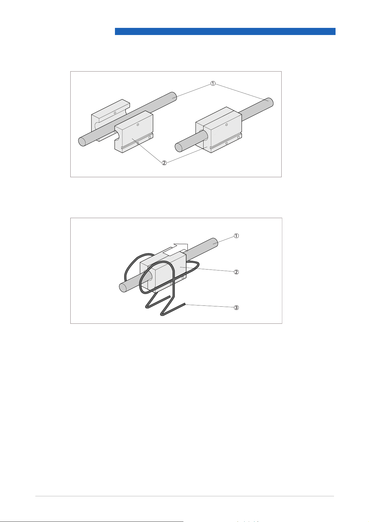
Figure 3-2: Placing the rod holder around the rod
1 Telescopic rod
2 Rod holder
OPTISENS PAS 2000
14
Figure 3-3: Inserting the rod holder into the mounting bracket
1 Telescopic rod
2 Rod holder
3 Mounting bracket
www.krohne.com 11/2008 • MA PAS 2000 R04 en
Page 15

OPTISENS PAS 2000
INSTALLATION 3
Figure 3-4: OPTISENS MAA 2000 Telescopic rod immersion holders
1 Telescopic rod
2 Sensor holder
3 Handrail with mounting bracket attached
4 Rod holder
5 Mounting bracket
CAUTION!
Do not extend the rod sections beyond the black lines. This could lead to rod damage.
CAUTION!
The sensor should be mounted in a vertical position. In some applications it may be desirable to
mount at a certain angle. In this case the angle from the horizontal plane should be greater than
or equal to 45
°
.
www.krohne.com11/2008 • MA PAS 2000 R04 en
15
Page 16

3 INSTALLATION
Mounting to telescopic rod immersion holder
• Mount the flexible mounting bracket on an existing handrail or on a separate holder, diameter
32...50 mm / 1.3...2.0" or square 28...42 mm / 1.1...1.7". The bent lip on the mounting plate
shall be on top and faced toward the liquid or tank.
• Adjust the mounting bracket to the correct angle and tighten the nuts.
i The bracket shall be fixed to the rail, and must not be able to rotate around it.
• Adjust the length of the telescopic rod as necessary by twisting the nuts while holding the rod.
Do not extend the rod sections beyond the black lines. This could lead to rod damage.
• Insert the PVC rod holder with the telescopic rod into the mounting bracket. Make sure that
the guide tracks of the rod holder are properly seated in the bracket.
• Fasten the safety-locking clamp.
• Check that the mounting bracket is safely fixed to the rail for the spring to work the way it is
intended.
3.3.3 MAA 2000 sensor holder and telescopic rod
OPTISENS PAS 2000
In standard applications the PAS 2000 telescopic rod version gets delivered pre-assembled. In
case the assembly needs to be done on side, the sensor is inserted into the telescopic rod and
fixed with two POM half shells, which additionally integrate the flushing system (see chapter 8).
NOTE!
To ensure easy access to the electrode in case of maintenance, make sure that the removable
part of the electrode holder is fixed clearly outside of the POM sensor holder.
16
www.krohne.com 11/2008 • MA PAS 2000 R04 en
Page 17

OPTISENS PAS 2000
INSTALLATION 3
3.3.4 Assembly of PAS 2000 to MAA 2000 slide rail immersion holder
As an alternative way of mounting the sensor, an adjustable slide rail holder is available.
1 Slide rail
2 Sensor
3 28 mm / 1.10" clamp
NOTE!
Please make sure that the assembly is mounted in a vertical position. In some applications it
may be desirable to mount at a certain angle. In this case the angle from the horizontal plane
should be greater than or equal to 45
°
.
Mounting instructions:
• Mount the slide rail assembly to the side wall of the basin or open channel using the two
predrilled holes. The adjustable limit stop should be on the bottom and the two sliding clamps
above.
• Take the two clamps off from the slide rail and mount them around the sensor housing. Please
make sure the two guide tracks line-up in one straight line to each other. See figure 3-4!
• Slide the sensor with the two clamps into the slide rail and make sure that the guide tracks of
the two clamps are properly seated.
• Adjust the sensor position as necessary (see chapter 3.3.2.) and fasten the limit stop.
www.krohne.com11/2008 • MA PAS 2000 R04 en
17
Page 18

3 INSTALLATION
3.3.5 Cable connections
Connect the sensor to the MAC 080 converter using the connector on the end of the attached
sensor cable. In the event that two sensors are to be connected to the same MAC 080 converter,
use the optional junction box.
See MAC 080 handbook for details.
3.4 Mounting the electrode
NOTE!
If the electrode has been in the cap for an extended period of time, salt crystals may need to be
rinsed away with water.
NOTE!
If the electrode cannot be immersed into the measuring media before it is put to use, the
electrode's small, plastic protective cover should be filled with a buffer solution of pH 7.
OPTISENS PAS 2000
• Connect the supply voltage. Remove the protective cap from the electrode probe.
• In order to mount an electrode the electrode holder at the lower end of the sensor must be
taken off.
• The electrode is mounted in the electrode holder by taking the enclosed nut, washer and O-
ring and threading them onto the electrode.
Note: Adjust the electrode position so that the diaphragm on the lower part of the electrode is
in contact with the measuring media.
• Tighten the nut with your hand.
• Remove the protective cover over the connector on top of the electrode and plug in the cable
coming from the electronic inside the sensor rod.
• Feed the cable into the sensor rod. It is easier to get the cable in place if the holder is turned
so the cable gets curled. Be careful not to damage the sealing or the cable.
• Mount the electrode holder back into the tube. Be careful not to damage the sealing.
18
www.krohne.com 11/2008 • MA PAS 2000 R04 en
Page 19

OPTISENS PAS 2000
INSTALLATION 3
Figure 3-5: Mounting the electrode
1 Diaphragm
2 Electrode
3 Nut
4 Washer
5 O-ring
www.krohne.com11/2008 • MA PAS 2000 R04 en
19
Page 20

4 ELECTRICAL CONNECTIONS
4.1 Safety instructions
DANGER!
All work on the electrical connections may only be carried out with the power disconnected. Take
note of the voltage data on the nameplate!
DANGER!
Observe the national regulations for electrical installations!
WARNING!
Observe without fail the local occupational health and safety regulations. Any work done on the
electrical components of the measuring device may only be carried out by properly trained
specialists.
OPTISENS PAS 2000
INFORMATION!
Look at the device nameplate to ensure that the device is delivered according to your order.
Check for the correct supply voltage printed on the nameplate.
4.2 Cable connections
INFORMATION!
Please refer to the MAC 080 manual for detailed information.
Connect the sensor to the MAC 080 converter using the connector on the end of the attached
sensor cable. In the event that two sensors are to be connected to the same converter, use the
optional junction box.
20
www.krohne.com 11/2008 • MA PAS 2000 R04 en
Page 21

OPTISENS PAS 2000
5.1 Sensor display
By simultaneously pressing ↓ and ^ you alter between MAC 080 main menu and the sensor
information display for the selected sensor. PAS 2000 has two information pages. The first one
shows in addition to the measured value maximum, minimum and average values for the last
24 hours. The values are based on hour values which means they may jump when a new hour
starts and the oldest is skipped.
The second information display shows the date of the last calibration (PAS 2000 pH only) and the
date the electrode was changed.
5.2 Menu for sensors
Use ↑ or ↓ to select the sensor in the main display. The menu for the selected sensor is accessed
by pressing ^ for five seconds. If the selected sensor is not active (the text No transmitter
shown) a warning is displayed that asks you to make another choice in order to show the sensor
menu.
OPERATION 5
No transmitter is
No transmitterNo transmitter
5.2.1 Menu for PAS 2000 pH
Menu "Settings"
Submenu Description
Tag
Tag Name of the sensor (10 characters) shown in the main display.
TagTag
I-Time
I-Time Integration time or dampening - can be set up to 999 seconds. Normal value is 5-10
I-TimeI-Time
Decimals
Decimals "1 or "2", number of decimals to show the measured value (only pH).
DecimalsDecimals
Reset day
Reset day "Yes" or "No", Yes resets the day calculation of min- max- and average.
Reset dayReset day
Analog
Analog "None" , "Out1", "Out2", "Out3", "Out4", "Out1+2", or "Out3+4". Pick which analog
AnalogAnalog
seconds.
output(s) to be used with sensor.
Menu "Calibrate"
Submenu Description
Take sample
Take sample "No", "Smart", or "manual". Refer to chapter 10 for details.
Take sampleTake sample
Cal Temp
Cal Temp Temperature at which calibration was done.
Cal TempCal Temp
Measure Temp
Measure Temp Temperature of measured media.
Measure TempMeasure Temp
Slope %
Slope % Shows the current condition of the electrode. A value between 93 % and 102 % is
Slope %Slope %
Sample 1 pH
Sample 1 pH Actual pH for the first buffer.
Sample 1 pHSample 1 pH
Sample 2 pH
Sample 2 pH Actual pH for the second buffer.
Sample 2 pHSample 2 pH
Calibrated
Calibrated Date of last air calibration.
CalibratedCalibrated
New electr.
New electr. Date when electrode was last changed. Push ^ to edit the date, then ^ again to store
New electr.New electr.
acceptable.
it.
www.krohne.com11/2008 • MA PAS 2000 R04 en
21
Page 22

5 OPERATION
Menu "Cleaning"
Submenu Description
Press ^ to go to the cleaning program
Cleaner
Cleaner "None", "Flush" or "Brush". Do not select “Brush” since this does not exist for this
CleanerCleaner
Interval min
Interval min 0...999 minutes, time between cleaning cycles.
Interval minInterval min
Length sec
Length sec 0...999 seconds, duration of flushing cycle.
Length secLength sec
Freeze sec
Freeze sec 0...999 seconds, extra freeze time of output signal after a flushing cycle.
Freeze secFreeze sec
Relay
Relay "-", "1", "2", "Along 1", or "Along 2". Select relay to operate solenoid for flush cycle if
RelayRelay
Next time
Next time The next scheduled cleaning time. Pushing ^ on this line will set the time to current
Next timeNext time
Menu "Scale / Alarm"
OPTISENS PAS 2000
sensor.
this sensor is a master with its own relay, or relay used by master if this sensor is a
slave. These are the same relays used for “Alarm relay
time and start a cleaning cycle. This could be used to test the "Flush" cycle.
Alarm relay” below.
Alarm relayAlarm relay
Submenu Description
Max
Max Measured value corresponding to 100 %, equal to 20 mA output signal (or 4 mA if 20-
MaxMax
Min
Min Measured value corresponding to 0 %, equal to 4 mA output signal (or 20 mA if 20-4 mA
MinMin
Hi-Alarm
Hi-Alarm Level that activates an alarm when exceeded, 0 = not in use.
Hi-AlarmHi-Alarm
Low-Alarm
Low-Alarm Level that activates an alarm when underpassed, 0 = not in use.
Low-AlarmLow-Alarm
Alarm Relay
Alarm Relay "-", "1", "2" or "1 and 2". Check that the relay is not being used for cleaning.
Alarm RelayAlarm Relay
4mA is used).
is used).
22
www.krohne.com 11/2008 • MA PAS 2000 R04 en
Page 23

OPTISENS PAS 2000
Menu "System"
Submenu Description
Type
Type Type of sensor, read only.
TypeType
Serial
Serial Serial number of the sensor, read only.
Serial Serial
SoftW
SoftW Software version of the sensor, read only.
SoftWSoftW
Press ^ to go to "info" read only menu. This menu is for KROHNE internal use.
Info
Info
InfoInfo
MS 1 mV Millivolt value for the first calibration point.
MS 2 mV Millivolt value for the second calibration point.
pH 1 pH for the first calibration point.
pH 2 pH for the second calibration point.
RV 0 mV Raw value for 0 mV.
RV 200 mV Raw value for 200 mV.
Ch1 Raw value.
MS mV Electrode output in millivolt.
pH Current measure value.
Samp/s Number of samples per second.
Service
Service Not accessible for users.
ServiceService
OPERATION 5
5.2.2 Menu for PAS 2000 ORP
Menu "Settings"
Submenu Description
Tag
Tag Name of the sensor (10 characters) shown in the main display.
TagTag
I-Time
I-Time Integration time or dampening - can be set up to 999 seconds. Normal value is 5-10
I-TimeI-Time
Analog
Analog "None", "Out1", "Out2", "Out3", "Out4", "Out1+2" or "Out3+4". Pick which analog
AnalogAnalog
seconds.
output(s) to be used with sensor.
Menu "Calibrate"
Submenu Description
Adjust
Adjust "No", "Reset" or "Set". Automatic offset adjustment.
AdjustAdjust
Offset
Offset Offset for the electrode.
OffsetOffset
@Buffer
@Buffer Buffer used for adjustment, saved during the automatic offset adjustment.
@Buffer@Buffer
ORP mV
ORP mV Current reading.
ORP mVORP mV
New electr.
New electr. Date when electrode was last changed. Push ^ to edit the date, then ^ again to store it.
New electr.New electr.
www.krohne.com11/2008 • MA PAS 2000 R04 en
23
Page 24

5 OPERATION
Menu "Cleaning"
Submenu Description
Press ^ to go to the cleaning program
Cleaner
Cleaner "None", "Flush" or "Brush". Do not select "Brush" since this does not exist for this
CleanerCleaner
Interval min
Interval min 0...999 minutes, time between cleaning cycles.
Interval minInterval min
Length sec
Length sec 0...999 seconds, duration of flushing cycle.
Length secLength sec
Freeze sec
Freeze sec 0...999 seconds, extra freeze time of output signal after a flushing cycle.
Freeze secFreeze sec
Relay
Relay "-", "1", "2", "Along 1" or "Along 2". Select relay to operate solenoid for flush cycle if
RelayRelay
Next time
Next time The next scheduled cleaning time. Pushing ^ on this line will set the time to current
Next timeNext time
Menu "Scale / Alarm"
OPTISENS PAS 2000
sensor.
this sensor is a master with its own relay, or relay used by master if this sensor is a
slave. These are the same relays used for "Alarm relay"
time and start a cleaning cycle. This could be used to test the "Flush" cycle.
"Alarm relay" below.
"Alarm relay""Alarm relay"
Submenu Description
Max
Max Measured value corresponding to 100 %, equal to 20 mA output signal (or 4 mA if 20-
MaxMax
Min
Min Measured value corresponding to 0 %, equal to 4 mA output signal (or 20 mA if 20-4 mA
MinMin
Hi-Alarm
Hi-Alarm Level that activates an alarm when exceeded, 0 = not in use.
Hi-AlarmHi-Alarm
Low-Alarm
Low-Alarm Level that activates an alarm when underpassed, 0 = not in use.
Low-AlarmLow-Alarm
Alarm Relay
Alarm Relay "-", "1", "2" or ”1 and 2”. Check that the relay is not being used for cleaning.
Alarm RelayAlarm Relay
4mA is used).
is used).
Menu "System"
Submenu Description
Type
Type Type of sensor, read only.
TypeType
Serial
Serial Serial number of the sensor, read only.
Serial Serial
SoftW
SoftW Software version of the sensor, read only.
SoftWSoftW
Press ^ to go to "info" read only menu. This menu is for KROHNE internal use.
Info
Info
InfoInfo
RV 0 mV Raw value for 0 mV.
RV 1000 mV Raw value for 1000 mV.
Ch1 Raw value.
ORP mV Current reading in millivolt.
Samp/s Number of samples per second.
Service
Service Not accessible for users.
ServiceService
5.3 Calibration
The sensor is shipped pre-calibrated, but since all electrodes are different, the sensor must be
calibrated with its electrode to give a good measurement. The electrode degrades by time and
calibrations shall be done regularly following a maintenance schedule.
24
www.krohne.com 11/2008 • MA PAS 2000 R04 en
Page 25

OPTISENS PAS 2000
The time between calibrations varies with the application, it is usually between one and ten
weeks. It is important that the sensor has been switched on for about 30 minutes prior to the
calibration in order to stabilize.
5.3.1 Calibrating pH
For a pH calibration there are two alternatives: smart or manual. Irrespective of the type of
calibration you chose, you need two pH buffers which both have a common, known temperature.
For a smart calibration you need two different buffer solutions with pH 4.00, 7.00, or 10.00. For a
manual calibration, two different buffer solutions can be used irrespective of the buffer value.
Remove the sensor and, if necessary the electrode as well, but make sure that the electrode is
still connected to the signal amplifier. Make sure that you have at least 2 standard buffers
available with pH 4 00, 7.00 or 10.00 of a known temperature (it is best to pour the buffers into
plastic cups). Now do the steps that follow:
OPERATION 5
• Enter the sensor menu. The output is frozen when the menu is opened.
• Open the "Calibrate" menu, select "Calibrate", then "Smart" or "Manual" and press ^.
• A window pops up and asks for the buffer temperature. Enter the temperature and press ^.
• MAC 080 will say "Put the electrode in buffer 1". Spray the electrode using clean water, then
immerse it in the first buffer, and press ^.
• The text will say "Waiting for stable signal xxx,x mV" (xxx,x is the millivolt signal from the
electrode). By pressing ^ you can select to abort the calibration or to accept the value shown.
• If smart calibration is used and MAC 080 recognizes the buffer, MAC 080 will suggest a pH
value showing the text "Accept smart calibration pH X.X". You can choose to accept the value
or to change it manually.
• If manual calibration is used MAC 080 will always ask for the value of the buffer, enter the
value and press ^.
• MAC 080 will now tell you "Put the electrode in buffer 2". Spray the electrode using clean
water, then immerse it in the second buffer, and press ^.
• The text will say "Waiting for stable signal xxx,x mV" (xxx,x is the millivolt signal from the
electrode). By pressing ^ you can select to abort the calibration or to accept the value shown.
• If smart calibration is used and MAC 080 recognizes the buffer, MAC 080 will suggest a pH
value showing the text "Accept smart calibration pH X.X". You can choose to accept the value
or to change it manually.
• If manual calibration is used MAC 080 will always ask for the value of the buffer, enter the
value and press ^.
• The second buffer is not accepted if it is less than 1 pH from buffer 1, if so the second
calibration will be repeated.
• When the calibration is finished the slope is shown in the display ("Slope XX%"). This gives an
indication of the shape of the electrode. A good electrode has a slope between 93 and 102 %.
• Press ^ to finish the calibration.
www.krohne.com11/2008 • MA PAS 2000 R04 en
25
Page 26

5 OPERATION
5.3.2 Adjusting ORP
The ORP sensor is not re-calibrated, an offset adjustment is done instead. The offset adjustment
can be done in two ways: automatic or manual. Irrespective of the way you chose, you need a
buffer with a known potential.
Remove the sensor and, if necessary the electrode as well, but make sure that the electrode is
still connected to the signal amplifier. Wipe clean the electrode before adjustment. Now do the
steps that follow:
• Spray the electrode using clean water, then immerse it in the first buffer, and wait for a stable
reading.
• Enter the sensor menu. The output is frozen when the menu is opened.
• Open the "Calibrate" menu, then select "Adjust", choose "Set" and press ^.
• A window pops up asking for the ORP potential. Enter it and then press ^. MAC 080 will
calculate the difference and use it as offset.
OPTISENS PAS 2000
5.4 Scaling
The Scale / Alarm
low boundaries for a 4...20 mA output signal. In addition, this menu allows the user to set high
and low alarm values to switch a relay when solids have reached critical points.
Max
Max sets the 20 mA point output
MaxMax
Min
Min sets the 4 mA point output (may be negative for special applications)
MinMin
Hi-Alarm
Hi-Alarm sets the high alarm set point; the value zero inactivates the alarm
Hi-AlarmHi-Alarm
Low-Alarm
Low-Alarm sets the low alarm set point; the value zero inactivates the alarm
Low-AlarmLow-Alarm
Scale / Alarm menu (see the OPTISENS MAC 080 manual) allows the user to set the high and
Scale / AlarmScale / Alarm
26
www.krohne.com 11/2008 • MA PAS 2000 R04 en
Page 27

OPTISENS PAS 2000
6.1 Maintenance
PAS 2000 sensors are easy to maintain. An electrode maintenance schedule should be kept,
listing when it is removed and cleaned. When this is done, the electrode should be checked
against a known buffer solution. If the control value does not match, a re-calibration should be
made.
Regularly check that the sensor does not get damp or wet inside during cleaning and other
activities. Also check that the electrode is correctly mounted in its holder to avoid leaking.
CAUTION!
Use distilled water for cleaning, otherwise the calibration and in worst case the total life time of
the electrode might be compromised.
6.1.1 Broken electrode
SERVICE 6
Lightning or static discharges during thunder storms may cause damage to the electrode, and
could also damage the signal amplifier. The electrode is the most exposed point since it is in
direct contact with the water and, consequently, the ground connection for a discharge.
Physical damage to the electrode usually makes measuring impossible. Make sure that neither
electrode nor cable is damaged.
6.1.2 Error messages
Display text Explanation Cause Solution
Unkown buffer The smart calibration
Same buffer During calibration the
does not recognize the
current buffer from the
signal of the electrode.
PAS 2000 pH does not
perceive a difference of
buffers.
Unknown buffers have
been used.
Broken sensor,
damaged electronic
components or bad
cable connection.
Same buffers have been
used.
The electrode or the
electronic components
in the sensor may be
broken.
Use standard buffers
4.00, 7.00 and 10.00.
Check or reseat cable
connection. Inspect
electrode and exchange
it if damaged.
Make sure that you use
two different buffers
during calibration.
Inspect electrode and
exchange it if damaged.
www.krohne.com11/2008 • MA PAS 2000 R04 en
27
Page 28

6 SERVICE
6.1.3 Incorrect measurements
Problem Solution
Dirty electrode Clean with distilled water
Insufficient or poor reference solution in the
electrode
Change of "slope" due to age Recalibration
Old electrode which gives slope <93 % Change electrode
6.1.4 Cleaning of the flushing nozzle
If the flushing nozzle becomes plugged, it can usually be cleaned by back flushing it with clean
water. Before attempting to backflush, close the valve for the flush water source and disconnect
the sensor flushing hose from the solenoid valve. Then, place a 12 mm hose over the flush
nozzle and carefully open the water valve.
OPTISENS PAS 2000
Refill/change reference solution (only for refillable
electrodes)
The pressure should clear the line of solids. If backflushing does not work initially, try cleaning
the flushing nozzle with a needle. Try backflushing the nozzle again as described above until
clean water comes out at the solenoid valve end of the hose.
6.2 Cleaning
The sensor is equipped with a flushing nozzle. The nozzle is used to direct the cleaning liquid
supplied through a 6 mm hose that is mounted along the sensor housing to flush the electrode. A
solenoid valve that is wired to a relay in the MAC 080 converter controls the air or liquid (see
handbook OPTISENS MAC 080).
Compressed air is recommended for most applications.
CAUTION!
For PAS 2000 submersible sensor the highest allowed flushing pressure is 6 bar / 87 psi. When
using air, 2 bar / 29 psi is usually sufficient.
NOTE!
Pay attention to the requirements for protection against backflow, according to the
EN 1717 standard for drinking water devices. If possible, use plant reuse water or effluent water
for cleaning.
28
www.krohne.com 11/2008 • MA PAS 2000 R04 en
Page 29

OPTISENS PAS 2000
Figure 6-1: Flushing system
1 Flush nozzle for automatic cleaning
NOTE!
In order to clean the sensor, flushing must be activated in the Settings
converter
SERVICE 6
Settings menu in the MAC 080
SettingsSettings
There are two different ways of cleaning a sensor: The sensor can either be cleaned as a master
or as a slave. Both options are described in the following instructions.
Cleaning the sensor as a master (sensor has its own relay)
• Select the sensor in the main menu by using ↑ or ↓.
• Press ^ for approximately five seconds to enter the sensor menu.
• Use ↑ or ↓ to select Cleaning
• In the Cleaning
Cleaning submenu, select Cleaner
CleaningCleaning
• Then specify the cleaning interval in minutes (Interval min
(Lenght sec
Lenght sec).
Lenght secLenght sec
Cleaning and press ^.
CleaningCleaning
Cleaner and set it to Flush
CleanerCleaner
Flush.
FlushFlush
Interval min) and the flush time in seconds
Interval minInterval min
• Specify the relay to be used according to the wiring inside the MAC 080 converter. For
example, if the solenoid is wired to relay #1, set Relay
• For sensors configured as masters, Next time
Next time displays the next time flush will be activated.
Next timeNext time
Relay to #1
RelayRelay
#1 for flushing.
#1#1
Pushing ^ will set it to current time and thus start cleaning.
• If needed, specify the extra freeze time in seconds (Freeze sec
Freeze sec).
Freeze secFreeze sec
www.krohne.com11/2008 • MA PAS 2000 R04 en
29
Page 30

6 SERVICE
Cleaning the sensor as a slave (along with another sensor)
• Select the sensor in the main menu by using ↑ or ↓.
• Press ^ for approximately five seconds to enter the sensor menu.
• Use ↑ or ↓ to select Cleaning
• The parameters Cleaner
the sensor being the master.
• Set Relay
Relay to Along #1
RelayRelay
• If needed, specify the extra freeze time in seconds (Freeze sec
Along #1 or Along #2
Along #1Along #1
Cleaning and press ^.
CleaningCleaning
Cleaner, Interval min
CleanerCleaner
6.3 Spare parts availability
The manufacturer adheres to the basic principle that operational spare parts for each device or
each important accessory part will be kept available for a period of 10 (ten) years after delivery of
the last production run for that device.
OPTISENS PAS 2000
Interval min and Lenght sec
Interval minInterval min
Along #2 depending on what relay the master sensor uses.
Along #2Along #2
Lenght sec in the Cleaning
Lenght secLenght sec
Freeze sec).
Freeze secFreeze sec
Cleaning submenu are set for
CleaningCleaning
Operational spare parts are defined as parts that are subject to faults in normal operation.
6.4 Availability of services
The manufacturer offers a range of services to support the customer after expiration of the
warranty. These include repair, technical support and training.
NOTE!
For more precise information, please contact your local representative.
30
www.krohne.com 11/2008 • MA PAS 2000 R04 en
Page 31

OPTISENS PAS 2000
6.5 Returning the device to the manufacturer
6.5.1 General information
This device has been carefully manufactured and tested. If installed and operated in accordance
with these operating instructions, it will rarely present any problems.
CAUTION!
Should you nevertheless need to return a device for inspection or repair, please pay strict
attention to the following points:
•
Due to statutory regulations on environmental protection and safeguarding the health and
safety of our personnel, manufacturer may only handle, test and repair returned devices that
have been in contact with products without risk to personnel and environment.
•
This means that the manufacturer can only service this device if it is accompanied by the
following certificate (see next section) confirming that the device is safe to handle.
SERVICE 6
CAUTION!
If the device has been operated with toxic, caustic, flammable or water-endangering products,
you are kindly requested:
•
to check and ensure, if necessary by rinsing or neutralizing, that all cavities are free from
such dangerous substances,
•
to enclose a certificate with the device confirming that is safe to handle and stating the
product used.
www.krohne.com11/2008 • MA PAS 2000 R04 en
31
Page 32

6 SERVICE
6.5.2 Form (for copying) to accompany a returned device
Company: Address:
Department: Name:
Tel. no.: Fax no.:
Manufacturer's order no. or serial no.:
The device has been operated with the following medium:
OPTISENS PAS 2000
This medium is: water-hazardous
toxic
caustic
flammable
We checked that all cavities in the device are free from such
substances.
We have flushed out and neutralized all cavities in the
device.
We hereby confirm that there is no risk to persons or the environment through any residual media
contained in the device when it is returned.
Date: Signature:
Stamp:
6.6 Disposal
CAUTION!
Disposal must be carried out in accordance with legislation applicable in your country.
32
www.krohne.com 11/2008 • MA PAS 2000 R04 en
Page 33

OPTISENS PAS 2000
7.1 Measuring principle
The pH value is normally measured with an electrode where pH is expressed as a function of
voltage. Today's electrodes often contain both a measuring electrode and a reference electrode,
which in combination provide a voltage in linear proportion to the pH value. Electrodes internally
combined with a reference and measuring cell are divided into two categories: gel electrodes
and refillable electrodes. The gel electrode is the simpler and less expensive type. There are a
number of different types of refillable electrodes for different applications, each with different
internal solutions that are to be added at regular intervals. KROHNE provides gel-filled glass
electrodes.
To compensate for the temperature dependence of the electrode, the temperature of the media
is measured by the transmitter and compensated automatically via the MAC 080 software. The
temperature can also be read in the MAC 080 converter and used as secondary value when a
transmitter is configured to use two analogue outputs.
TECHNICAL DATA 7
NOTE!
The build in temperature measurement is not a precision measurement, but shall be seen as an
indication.
The temperature compensation can also be set manually to a fixed value via the MAC 080 menu.
All settings are made in the MAC 080 converter using a self-instructing menu controlled by just
three keys. The output signal is frozen when you switch to menu mode so that the output signal
will not change during procedures such a re-calibration.
The MAC 080 has two 4-20 mA outputs (extendable to four), and relay outputs for alarm and
cleaning of the electrode. The current pH/mV values and the temperature measurement of the
active sensor are continuously displayed in the MAC 080 display. Maximum, minimum and
average values for the last 24 hours can be obtained by pressing two buttons.
www.krohne.com11/2008 • MA PAS 2000 R04 en
33
Page 34

7 TECHNICAL DATA
7.2 Data table
Measuring system
Measuring principle Potentiometric measurement
Field of application Continuous measurement of pH
Modular design A typical measuring system
Measuring accuracy ± 1.5 % FS (Full scale) ± 1.5 % FS (Full scale)
Measuring range 0…14 pH -1500…+1500 mV (ORP)
OPTISENS PAS 2000
OPTISENS PAS 2000 pH OPTISENS PAS 2000 ORP
using combination electrodes
in waste water applications
consists of:
MAC 080 Multiparameter
Converter
1 (or up to 4) OPTISENS 2000
Sensors
Solenoid valves for flushing Solenoid valves for flushing
MAA 2000 mounting assemblies MAA 2000 mounting assemblies
Potentiometric measurement
using combination electrodes
Continuous measurement of ORP
in waste water applications
A typical measuring system
consists of:
MAC 080 Multiparameter
Converter
1 (or up to 4) OPTISENS 2000
Sensors
Operating conditions
Process temperature 0…60°C / 32…140°F 0…60°C / 32…140°F
Max. immersion depth 0.8 m / 2.6 ft 0.8 m / 2.6 ft
Calibration Two point calibration (smart or
manual) using two buffer
solutions
Offset calibration (automatic or
manual) using clean water and
one buffer solution
Installation conditions
PAS 2000 + MAA 2000 Telescopic
rod for immersion into basins
PAS 2000 + MAA 2000 Slide rail
for side wall mounting
Flushing With filtered air or clean water
Process connection Submerged in open channels/basins
The telescopic rod can be fixed to the handrail using a flexible spring
loaded mounting bracket
Fully extended: 2.7 m / 8.9 ft
Mounting bracket for:
- Round handrails ø = 32…50 mm / 1.3…2"
- Square cross-sections 28…42 mm / 1.1…1.7"
Installation on the side wall of basins; retractable holder with
adjustable stop
Pressure: 2…6bar / 29…87 psi
Hose: 1/4" external diameter; length: 10 m / 32.8 ft
Solenoid valve: available in 230 V and 117 V versions; up to 2 sensors
can be connected to one solenoid valve
34
www.krohne.com 11/2008 • MA PAS 2000 R04 en
Page 35

OPTISENS PAS 2000
Materials
Enclosure 316SS 316SS
Cable feed through PVC PVC
Sensor holder for telescopic rod POM POM
Connection cable 5-pin M 12 contact; fixed on
Flush hose PE PE
Electrode Design: Combination electrode
TECHNICAL DATA 7
OPTISENS PAS 2000 pH OPTISENS PAS 2000 ORP
5-pin M 12 contact; fixed on
sensor side, shielded; 10 m /
32.8 ft long; insulation: Hytrel
12 mm / 0.47"; Length: 120 mm /
4.72"
PG13.5 threated cap PG13.5 threated cap
KCL-Gel KCL-Gel
Connector: KOAX Connector: KOAX
sensor side, shielded; 10 m /
32.8 ft long; insulation: Hytrel
Design: Combination electrode
12 mm / 0.47"; Length: 120 mm /
4.72"
Approvals
Protection class IP65 (Nema 4x)
Approval mark CE
EMC (89/336/EEC) Electromagnetic compatibility (EMC) in accordance with:
EN 61000-6-4:2001 Emission standard for industrial environments
EN 61000-6-2:2001 Immunity for industrial environments
Low Voltage Directive
(89/336/EEC)
Safety requirements for electrical equipment for measurement,
control, and laboratory use in accordance with EN 61010-1:2001
www.krohne.com11/2008 • MA PAS 2000 R04 en
35
Page 36

7 TECHNICAL DATA
7.3 Dimensions & Weight
OPTISENS PAS 2000
36
Dimensions [mm] Dimensions [inches]
a 1085 42.7
b 1000 39.4
c Ø28 Ø1.1
d 35 1.4
Weight [kg] Weight [lbs]
PAS 2000 length 1000 mm / 39.4" 1.8 4
www.krohne.com 11/2008 • MA PAS 2000 R04 en
Page 37

OPTISENS PAS 2000
MAA 2000 sensor holder and telescopic rod
TECHNICAL DATA 7
1 Flexible telescopic rod
2 Large diameter sensor holder
3 Flush nozzle for automatic cleaning
Weight [kg] Weight [lbs]
MAA 2000 sensor holder 0.5 1.1
www.krohne.com11/2008 • MA PAS 2000 R04 en
37
Page 38

8 APPENDIX
8.1 pH as a function of mV
The pH-value is the negative logarithm of the hydrogen ion concentration, and it is directly
related to the proportion of hydrogen ions H
electrode measures excess or deficit of the hydrogen ions and gives a proportional millivolt
signal as output. The signal is 59.16 mV per 1 pH at 77°F. In clean water there is a total balance
between hydrogen ions and hydroxide ions, the output from the electrode is 0.0 mV and pH is 7.
The millivolt signal is measured by PAS 2000 pH and the corresponding pH is calculated in
MAC 080.
mV pH H+ ions, mol/l OH- ions, mol/l Example
414 0 1 0.00000000000001
355 1 0.1 0.0000000000001
296 2 0.01 0.000000000001 Coca Cola
237 3 0.001 0.00000000001
177 4 0.0001 0.0000000001 Orange juice
118 5 0.00001 0.000000001
59 6 0.000001 0.00000001 Milk
0 7 0.0000001 0.0000001 Clean water
-59 8 0.00000001 0.000001 Blood
-118 9 0.000000001 0.00001
-177 10 0.0000000001 0.0001
-237 11 0.00000000001 0.001
-296 12 0.000000000001 0.01
-355 13 0.0000000000001 0.1
-414 14 0.00000000000001 1 Sulfa
OPTISENS PAS 2000
+
to hydroxide ions OH- in the media. The pH-
38
www.krohne.com 11/2008 • MA PAS 2000 R04 en
Page 39

OPTISENS PAS 2000
8.2 pH temperature dependency
The output from a pH-electrode varies with the temperature in a predictable way. The size of the
variation depends on both the temperature and the pH being measured.
°C °F pH pH pH pH pH pH pH pH pH pH pH pH
5 41 2.30 3.24 4.18 5.12 6.06 7.00 8.06 9.12 10.18 11.24 12.30 13.36
15 59 2.15 3.12 4.09 5.06 6.03 7.00 8.03 9.06 10.09 11.12 12.15 13.18
25 77 2.00 3.00 4.00 5.00 6.00 7.00 8.00 9.00 10.00 11.00 12.00 13.00
35 95 1.85 2.88 3.91 4.94 5.97 7.00 7.97 8.94 9.91 10.88 11.85 12.82
45 113 1.70 2.76 3.82 4.88 5.94 7.00 7.94 8.88 9.82 10.76 11.70 12.64
55 131 1.55 2.64 3.73 4.82 5.91 7.00 7.91 88.2 9.73 10.64 11.55 12.46
65 149 1.40 2.52 3.64 4.76 5.88 7.00 7.88 8.76 9.64 10.52 11.40 12.28
75 167 1.25 2.40 3.55 4.70 5.85 7.00 7.85 8.70 9.55 10.40 11.25 12.10
85 185 1.10 2.28 3.46 4.64 5.82 7.00 7.82 8.64 9.46 10.28 11.10 11.92
95 203 0.95 2.16 3.37 4.58 5.79 7.00 7.79 8.58 9.37 10.16 10.95 11.74
APPENDIX 8
At pH 7 or 78°F the temperature error is zero. If temperature or pH changes the temperature
error is calculated using the following formula: 0.03 pH-difference / pH / 10°C. PAS 2000 pH has
a built in compensation for the temperature error provided that the correct temperature of
calibration buffers and measured media is entered.
www.krohne.com11/2008 • MA PAS 2000 R04 en
39
Page 40

8 APPENDIX
8.3 Support information form
Before calling the customer support, please collect the information in this form and have it at
hand.
Company:
Company: Name:
Company:Company:
Phone:
Phone: E-mail:
Phone:Phone:
Sensor type:
Sensor type: Position / Tag:
Sensor type:Sensor type:
Name:
Name:Name:
E-mail:
E-mail:E-mail:
Position / Tag:
Position / Tag:Position / Tag:
OPTISENS PAS 2000
First go to the converter menu by pressing ↑ and ^ simultaneously for five seconds. Then select System
and press ^. Write down the following information.
Version:
Version:
Version:Version:
Serial:
Serial:
Serial:Serial:
Box temp:
Box temp:
Box temp:Box temp:
Leave the converter menu by pressing ↑ and ^ simultaneously. Use ↑ and ↓ to select the sensor in the
main display. Go to the sensor menu by pressing ^ for five seconds. Then select System
Write down the following information.
Type:
Type: SoftW:
Type:Type:
Serial:
Serial:
Serial:Serial:
Select Info
Info, then press ^ to go to the Info menu.
InfoInfo
MS 1 mV
MS 1 mV 1 MS 2 mV
MS 1 mVMS 1 mV
pH 1
pH 1 1 pH 2
pH 1pH 1
RV 0 mV
RV 0 mV RV 200 mV
RV 0 mVRV 0 mV
RV 1000 mV
RV 1000 mV 2 Ch1
RV 1000 mVRV 1000 mV
MS mV
MS mV 1 ORP mV
MS mVMS mV
pH
pH 1
pHpH
Leave the menu by pressing ↑ and ^ simultaneously.
1 Only for PAS 2000 ph
2 Only for PAS 2000 ORP
SoftW:
SoftW:SoftW:
MS 2 mV 1
MS 2 mVMS 2 mV
pH 2 1
pH 2pH 2
RV 200 mV 1
RV 200 mVRV 200 mV
Ch1
Ch1Ch1
ORP mV 2
ORP mVORP mV
System and press ^.
SystemSystem
System
SystemSystem
40
www.krohne.com 11/2008 • MA PAS 2000 R04 en
Page 41

OPTISENS PAS 2000
8.4 Setup information form
This form can be used to document the setup of the sensor.
Sensor type
Sensor type
Sensor typeSensor type
Position / Tag
Position / Tag
Position / TagPosition / Tag
In the System
System submenu of the sensor menu the following information can be collected:
SystemSystem
Serial
Serial
SerialSerial
SoftW
SoftW
SoftWSoftW
In the Settings
Settings submenu of the sensor menu the following parameters can be set:
SettingsSettings
I-time
I-time
I-timeI-time
APPENDIX 8
Decimals
Decimals
DecimalsDecimals
1
Analog
Analog
AnalogAnalog
In the Cleaning
Cleaning submenu of the sensor menu the following parameters can be set:
CleaningCleaning
Cleaner
Cleaner
CleanerCleaner
Cleaning interval
Cleaning interval
Cleaning intervalCleaning interval
Cleaning length
Cleaning length
Cleaning lengthCleaning length
Cleaning relay
Cleaning relay
Cleaning relayCleaning relay
In the Scale / Alarm
Scale / Alarm submenu of the sensor menu the following parameters can be set:
Scale / AlarmScale / Alarm
Max
Max
MaxMax
Min
Min
MinMin
High alarm
High alarm
High alarmHigh alarm
Low alarm
Low alarm
Low alarmLow alarm
Alarm relay
Alarm relay
Alarm relayAlarm relay
Leave the menu by pressing ↑ and ^ simultaneously.
1 Only for PAS 2000 pH
www.krohne.com11/2008 • MA PAS 2000 R04 en
41
Page 42

8 APPENDIX
OPTISENS PAS 2000
42
www.krohne.com 11/2008 • MA PAS 2000 R04 en
Page 43

OPTISENS PAS 2000
APPENDIX 8
www.krohne.com11/2008 • MA PAS 2000 R04 en
43
Page 44

OPTISENS PAS 2000 nnnnnnnnnnnnnnnnnnnnnnnnnnnnnnnnnnnnnnnnnnnnnnnnnnnn
n
KROHNE measuring technology - Product overview
• Electromagnetic flowmeters • Level measuring instruments
• Variable area flowmeters • Temperature measuring instruments
• Mass flowmeters • Pressure measuring instruments
• Ultrasonic flowmeters • Analysis
• Vortex flowmeters • Oil and gas industry
• Flow controllers
Addresses:
Great Britain
Germany
Northern sales office
KROHNE Messtechnik GmbH & Co. KG
Bremer Str. 133
D-21073 Hamburg
Phone:+49 (0)40 767 3340
Fax:+49 (0)40 767 33412
nord@krohne.com
ZIP code: 10000 - 29999, 49000 - 49999
Western and middle sales office
KROHNE Messtechnik GmbH & Co. KG
Ludwig-Krohne-Straße
D-47058 Duisburg
Phone:+49 (0)203 301 4416
Fax:+49 (0)203 301 10416
west@krohne.com
ZIP code: 30000 - 34999, 37000 48000, 50000 - 53999, 57000 - 59999,
98000 - 99999
Southern sales office
KROHNE Messtechnik GmbH & Co. KG
Landsberger Str. 392
D-81241 Munich
Phone:+49 (0)89 121 5620
Fax:+49 (0)89 129 6190
sued@krohne.com
ZIP code: 0 - 9999, 80000 - 89999,
90000 - 97999
Southwestern sales office
KROHNE Messtechnik GmbH & Co. KG
Rüdesheimer Str. 40
D-65239 Hochheim/Main
Phone: +49(0)6146) 827 30
Fax:+49 (0)6146 827 312
rhein-main@krohne.com
ZIP code: 35000 - 36999, 54000 56999, 60000 - 79999
Instrumentation and control
equipment catalog
TABLAR Messtechnik GmbH
Ludwig-Krohne-Str. 5
D-47058 Duisburg
Phone:+49 (0)2 03 305 88 0
Fax:+49 (0)2 03 305 8888
kontakt@tablar.de; www.tab lar.de
KROHNE sales
companies
International
Australia
Australia
AustraliaAustralia
KROHNE Australia Pty Ltd
Quantum Business Park 10/287
Victoria Rd Rydalmere NSW 2116
Phone: +61 2 8846 1700
Fax: +61 2 8846 1755
krohne@krohne.com.au
Austria
Austria
AustriaAustria
KROHNE Gesellschaft m.b.H.
Modecenterstraße 14
A-1030 Vienna
Phone:+43 (0)1/203 45 32
Fax:+43 (0)1/203 45 32 99
info@krohne.at
Belgium
Belgium
Belgium Belgium
KROHNE Belgium N.V.
Brusselstraat 320
B-1702 Groot Bijgaarden
Phone:+32 (0)2 4 66 00 10
Fax:+32 (0)2 4 66 08 00
krohne@krohne.be
Brazil
Brazil
Brazil Brazil
KROHNE Conaut Controles
Automaticos Ltda.
Estrada Das Águas Espraiadas, 230
C.P. 56 06835 - 080 EMBU - SP
Phone:+55 (0)11-4785-2700
Fax:+55 (0)11 4785-2768
conaut@conaut.com.br
China
China
ChinaChina
KROHNE Measurement Instruments
(Shanghai) Co. Ltd., (KMIC)
9th Floor, Puyuan Science Park,
Building A
396 Guilin Road
Shanghai 200233
Tel.: +86 (021) 6470 5656
Fax: +86 (021) 6451 6408
info@krohne-asia.com
Czech Republic
Czech Republic
Czech RepublicCzech Republic
Krohne CZ, spol. s r.o.
Sobìsická 156
63800 Brno
Phone: +420 (0)545.242 627
Fax: +420 (0)545 220 093
brno@krohne.cz
France
France
FranceFrance
KROHNE S.A.S.
Les Ors BP 98
F-26103 ROMANS Cedex
Phone:+33 (0)4 75 05 44 00
Fax:+33 (0)4 75 05 00 48
info@krohne.fr
Great Britain
Great BritainGreat Britain
KROHNE Ltd.
Rutherford Drive
Park Farm Industrial Estate
Wellingborough
Northants NN8 6AE
Phone:+44 (0)19 33 408 500
Fax:+44 (0)19 33 408 501
info@krohne.co.uk
CIS
CIS
CISCIS
Kanex KROHNE Engineering AG
Business Centre "POLLARS", office
164
Derbenevskaya nab., 11-B
113114 Moscow/Russia
Tel. / Fax: +7 (0)495 913-68-41
Tel. / Fax: +7 (0)495 913-68-42
Tel. / Fax: +7 (0)495 913-68-43
Tel. / Fax: +7 (0)495 913-68-44
krohne@krohne.ru
India
India
IndiaIndia
Krohne Marshall Ltd.
A-34/35, M.I.D.C. Industrial Area,
H-Block
Pimpri Poona 411018
Phone:+91 (0)202 744 2020
Fax:+91 (0)202 744 2020
pcu@vsnl.net
Iran
Iran
IranIran
KROHNE Liaison Office
North Sohrevardi Ave. 26,
Sarmad St., Apt. #9
Tehran 15539
Phone: +9821 8874 5973
Fax: +9821 8850 1268
krohne@krohneiran.com
Italy
Italy
ItalyItaly
KROHNE Italia Srl.
Via V. Monti 75
I-20145 Milan
Phone:+39 02 4300 661
Fax:+39 02 4300 6666
info@krohne.it
Korea
Korea
KoreaKorea
KROHNE Korea
Room 508 Miwon Bldg 43
Yoido-Dong Youngd eungpo-Ku
Seoul, Korea
Phone: 00-82-2-782-1900
Fax: 00-82-2-780-1749
mail@krohne.co.kr
Netherlands
Netherlands
NetherlandsNetherlands
KROHNE Nederland B.V.
Kerkeplaat 14
NL-3313 LC Dordrecht
Phone:+31 (0)78 630 6200
Fax:+31 (0)78 630 6405
Service Direct: +31 (0)78 630 6222
info@krohne.nl
Norway
Norway
NorwayNorway
KROHNE Norway A.S.
Ekholtveien 114
NO-1521 Moss
Phone:+47 (0)69 264 860
Fax:+47 (0)69 267 333
postmaster@krohne.no
Poland
Poland
PolandPoland
KROHNE Polska Sp.z.o.o.
ul. Stary Rynek Oliwski 8a
80-324 Gdansk
Phone: +48 (0)58 520 9211
Fax.:+48 (0)58 520 9212
info@krohne.pl
Switzerland
Switzerland
SwitzerlandSwitzerland
KROHNE AG
Uferstr. 90
CH-4019 Basel
Phone:+41 (0)61 638 30 30
Fax:+41 (0)61 638 30 40
info@krohne.ch
Singapore
Singapore
SingaporeSingapore
Tokyo Keiso - KROHNE (Singapore)
Pte. Ltd.
14, International Bus iness Park,
Jurong East
Chiyoda Building, #01-01/02
Singapore 609922
Phone: (65) 6567 4548
Fax : (65) 6567 9874
tks@tokyokeiso-krohne.com.sg
Republic of South Africa
Republic of South Africa
Republic of South AfricaRepublic of South Africa
KROHNE Pty. Ltd.
Bushbock Close
Corporate Park South
Midrand, Gauteng
P.O. Box 2069
Midrand, 1685
Tel.: +27 (0)11 314 1391
Fax: +27 (0)11 314 1681
midrand@krohne.co.za
Spain
Spain
SpainSpain
I.I. KROHNE IBERIA, S.r.l.
Poligono Indust rial Nilo
Calle Brasil, nº. 5
28806 Alcalá de Henares Madrid
Phone: +34 (0)91 883 2152
Fax: +34 (0)91 883 4854
krohne@krohne.es
USA
USA
USAUSA
KROHNE, Inc.
7 Dearborn Road
Peabody, MA 01960
Phone: +1 (800) FLOWING
Phone: +1 (978) 535 6060 (in MA)
info@krohne.com
Representatives
Algeria
Argentina
Cameroon
Canada
Chile
Columbia
Croatia
Denmark
Ecuador
Egypt
Finland
Gabon
Ghana
Greece
Hong Kong
Hungary
Indonesia
Iran
Ireland
Israel
Ivory Coast
Japan
Jordan
Kuwait
Libya
Lithuania
Malaysia
Mauritius
Mexico
Morocco
New Zealand
Peru
Portugal
Romania
Saudi Arabia
Senegal
Slovakia
Slovenia
Sweden
Taiwan
Thailand
Tunisia
Turkey
Venezuela
Yugoslavia
Other countries
KROHNE Messtechnik GmbH & Co. KG
Ludwig-Krohne-Str. 5
D-47058 Duisburg
Phone:+49 (0)203 301 0
Fax:+49 (0)203 301 389
export@krohne.com
© KROHNE 11/2008 MA PAS 2000 R04 en Subject to change without notice
www.krohne.com
 Loading...