

Page 1

Digital measuring converter for ion-sensitive measurements
Page 2

Copyright
All rights reserved.
Version A, Copyright 2006 by
KROHNE Messtechnik GmbH & Co.KG • Ludwig-Krohne-Straße 5 • 47058 Duisburg
Tel. +49 (203) 301-0
www.krohne.com
2
Page 3

1
Safety Information....................................................................................................4
1.1 General information ........................................................................................................................................ 4
1.2 Display conventions ........................................................................................................................................ 5
1.3 Installation .......................................................................................................................................................... 6
1.4 Handling and Use............................................................................................................................................. 7
1.5 Identification...................................................................................................................................................... 8
2
Description..................................................................................................................9
2.1 Product................................................................................................................................................................. 9
3
Installation.................................................................................................................11
3.1 Mounting to wall or weather cover .........................................................................................................11
3.2 Electrical connection.....................................................................................................................................12
4
Basic Functiions and Start Up ............................................................................14
4.1 Front of the converter...................................................................................................................................14
4.2 Measuring channel display .........................................................................................................................15
4.3 Plug Connections (Probes)..........................................................................................................................15
5
Start Up.......................................................................................................................17
5.1 Important information .................................................................................................................................17
5.2 Switch On / Off ................................................................................................................................................18
5.3 Change measuring channel display ........................................................................................................19
5.4 Control button functions.............................................................................................................................20
5.5 Menu settings ..................................................................................................................................................21
5.5.1 Parameter-menu ................................................................................................................. 21
5.5.2 Branching of Parameter menu into further sub-menus....................................................... 22
5.5.3 General Menu ..................................................................................................................... 24
5.5.4 Data logger menu ............................................................................................................... 25
5.6 Key lock..............................................................................................................................................................26
5.7 The most important settings for a quick start......................................................................................27
6
Calibration .................................................................................................................29
6.1 Preparation for sensor calibration ............................................................................................................29
6.2 2-Point-Calibration ........................................................................................................................................30
6.2.1 Producing calibration standards (ISE)................................................................................ 31
6.2.2 Carrying out 2-Point-Calibration........................................................................................ 32
6.3 Offset Calibration ...........................................................................................................................................36
6.4 General settings..............................................................................................................................................39
6.5 Hydrograph Menu..........................................................................................................................................42
6.6 Channel-specific settings ............................................................................................................................44
6.7 Calibration submenu ....................................................................................................................................49
6.8 Sensor date submenu...................................................................................................................................51
6.9 Data logger settings ......................................................................................................................................53
www.krohne.com
3
Page 4

1 Safety Information
1.1 General information
For your protection, please read and pay attention to all safety information prior to start-up of your
converter PAM2080.
Retain these instructions and all other information for future reference.
Utilisation other than that described here compromises the safety of persons and the entire measuring
equipment and is therefore impermissible.
The manufacturer will assume no liability for damage arising from improper or non-compliant utilisation
of the products.
DANGER!
Improper handling can lead to electric shock. “Hazardous voltages” representing a risk of electric shock
for humans may be present on non-insulated parts in the product’s casing. Therefore cut off the device’s
power supply prior to opening the connection cavity cover.
Assembly, electrical connection, start-up, operation and maintenance of the measuring equipment may
only be effected by trained personnel who must be authorised by the system operator for the activities
indicated. The trained personnel must have read and understood these operating instructions and must
follow the directions in these operating instructions.
Check that all connections are correct prior to starting up the measuring point as a whole. Make sure that
electrical cables and hose connections are not damaged.
Do not commission damaged products and protect these products from unintentional start-up. Label the
damaged product as defective.
If faults cannot be eliminated, you must remove the products from operation and protect them from
unintentional start-up. Repairs that are not described in these operating instructions must only be carried
out directly with the manufacturer or via the service department of KROHNE.
www.krohne.com
4
Page 5
1.2 Display conventions
The following symbols are used to help you navigate this document more easily:
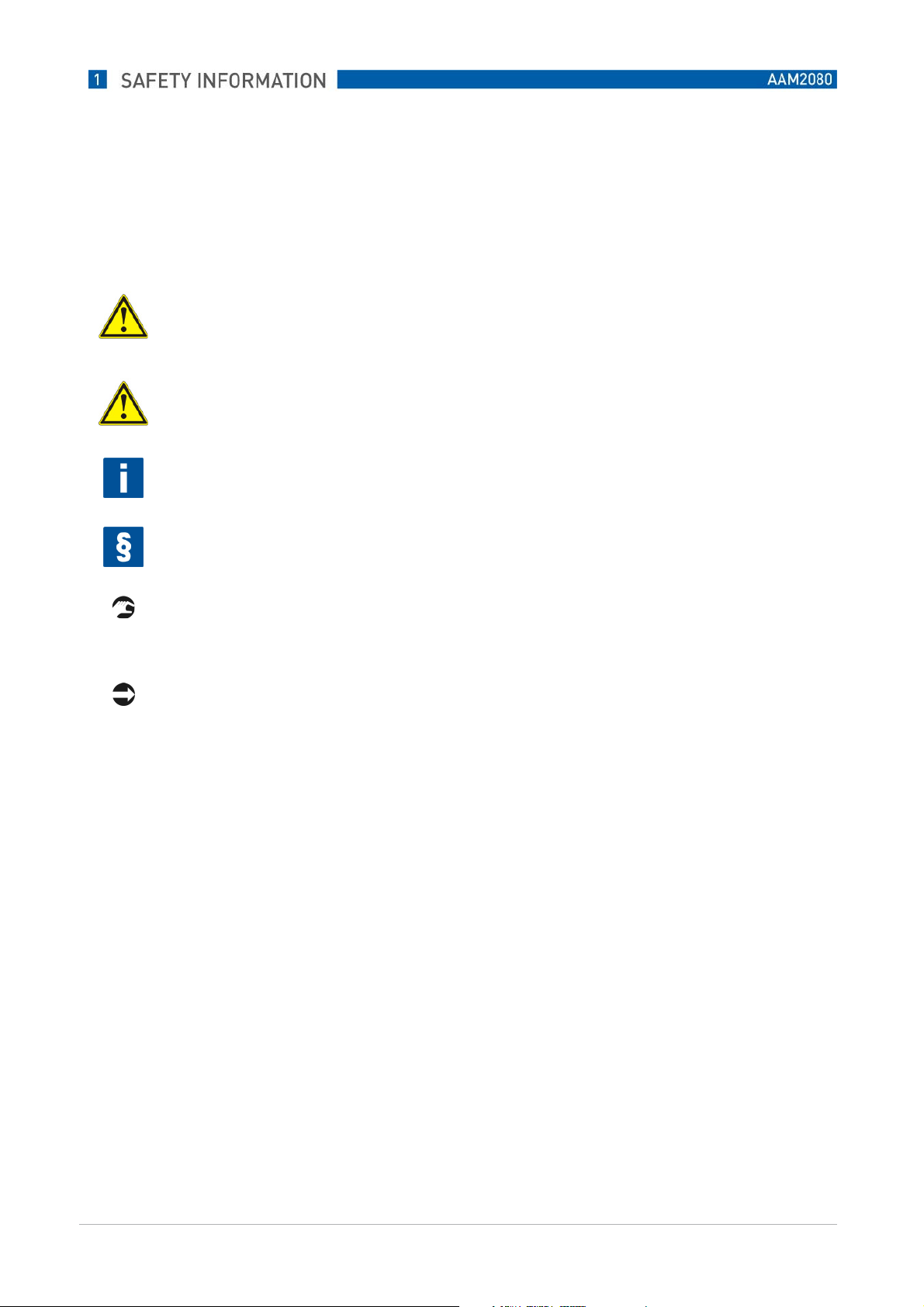
WARNING! DANGER!
These warning signs must be observed without fail. Even only partial disreagarding such warnings can
result in serious health damage, damage to the device itself or to parts of the oprator´s plant.
CAUTION!
These warning signs must be observed without fail. Even only partial disreagarding such warnings can
lead to improper functioning of the device.
NOTE!
This symbol designates important information for the handling of the device.
LEGAL NOTICE!
This symbol designates information on statutory directives and standards.
HANDLING!
This symbol designates all instructions for actions to be carried out by the operator in the specified
sequence.
CONSEQUENCE!
This symbol designates all important consequences of the previous actions..
www.krohne.com
5
Page 6

1.3 Installation
CAUTION!
First assemble the device at the definitive place of use. Using suitable screws, fix the device to a weatherprotected wall or weather cover, e.g. a pedestal.
Effect all electrical connections before switching on the device, otherwise damage is possible.
Water, moisture and dust
Converter PAM2080 is designed according to protection class IP 54 and correspondingly protected
against penetration of water, moisture and dust. Nevertheless, avoid extreme conditions.
Heat
Do not install converter PAM2080 close to heat sources, such as heaters, radiators, conduits containing
hot mediums. Avoid direct sunlight.
Power supply
Converter PAM2080 is equipped with a multi-range switching power supply and must only be operated
live within the indicated range (see Technical Data).
Mains connection
To ensure safe and impeccable operation converter PAM2080 must be securely connected to a mains
connection box by means of a mains cable.
Accessories
To ensure safe operation we recommend utilisation of our accessories.
www.krohne.com
6
Page 7

1.4 Handling and Use
Cleaning
Where necessary, clean converter PAM2080 using a damp cloth and mild cleaning products. Use no
abrasive cleaning or scouring products (front film is sensitive to scratches). Never use solvents or
cleaning sprays containing solvents.
Decomissioning
Decommission the device if you notice damage to the casing, if you notice moisture in the device (e.g.
fogged display) or if the converter does not function as prescribed.
Transportation / return
It is recommended to transport the device in its original packaging across large distances or when
returning the device.
In the event of repair please send the device – cleaned – to the KROHNE sales office covering your area.
As far as possible, use the original packaging when doing so.
Please enclose the completed hazardous goods sheet (copy penultimate page of these operating
instructions) with the packaging and additionally with the dispatch documents.
Play your part in environmental protection
Converter PAM2080 also contains electronic parts that contain precious metals in small quantities. These
raw materials are fully recyclable. Please deposit electrical devices intended for disposal at appropriate
collection points (electrical scrap).
Unauthorised interventions in the device render the guarantee ineffective.
www.krohne.com
7
Page 8

1.5 Identification
Type plate
KROHNE
KROHNE
KROHNEKROHNE
PPPPAM2080
AM2080
AM2080AM2080
230 VAC
ambient.Temp. Umgebungstemp. +5–50°C
Output 1 – 4: 0/4 .. 20 mA
Ausgang 1 – 4: 0/4 .. 20 mA
CERTIFICATE AND APPROVALS
Declaration of compliance:
The product fulfils the statutory requirements of the harmonised European standards. KROHNE confirms
compliance with the standards by attaching the CE symbol.
IP 65
www.krohne.com
8
Page 9

2 Description
2.1 Product
Digital converter for analysing and displaying measured parameters of KROHNE sensors.
--
Uninterrupted, secure data communication between MiniCVal components by means of IC bus
--
technology
8 freely parameterisable channels for easy allocation of up to 8 sensors.
--
4 analogue outputs 0/4 .. 20 mA for free allocation of channels.
--
5 configurable relays, freely adjustable for thresholds (min./max.) or as fault sensors. Collective
--
notification for several channels or individually.
Full-graphic liquid crystal display (background illuminated) with clear-to-view, large display of
--
individual parameters.
Additionally, the most important information at a glance: calibration status, sensor condition, clean
--
function.
Data logger function with adjustable graphical hydrograph display, for improved on-site trend
--
detection and operating status diagnosis.
The following parameters are pre-configured factory-side and directly retrievable via the menu:
--
Semi-conductor
--
pH value (pH)
--
Redox (mV)
--
Ammoniac (NH3)
--
Ammonium (NH4 / NH4-N))
--
Nitrate (NO3 / NO3-N)
--
Nitrite (NO2 / NO2-N)
--
Water hardness (°GH Ca/Mg)
--
Sulfite (SO22-)
--
Sulfide (S2-)
--
Cyanide (CN-)
--
Chloride (Cl-)
--
Fluoride (F-)
--
Bromide (Br-)
--
Sodium (Na+)
--
Potassium (K+)
--
Oxygen (O2 dissolved)
--
Chlorine (Cl2 dissolved)
--
o-Phosphate (PO43-)
--
Lithium (Li+)
--
Refraction
--
Lead (Pb2+)
--
www.krohne.com
9
Page 10

Further parameters on request.
New parameters and new firmware can be imported into converter PAM2080 at any time via software
update. (Information on this from KROHNE service department or at www.krohne.de).
www.krohne.com
10
Page 11

3 Installation
3.1 Mounting to wall or weather cover
Using appropriate screws, (d=6 mm), fix converter PAM2080 to straight surfaces (wall) or to a
weather cover (for example weather cover ZAB-04, order no. 5.520.004 with pre-drilled holes).
You gain access to the lower fixing eyes by opening the terminal connection cavity (all dimensions
indicated in mm).
www.krohne.com
11
Page 12

Relais Error
)
3.2 Electrical connection
WARNING!
Electrical connection may only be carried out by authorised trained personnel.
Ensure that there is no voltage present in the mains cable before connection work commences.
Prior to connection, make sure that the mains voltage matches the voltage indicated on the type plate!
A clearly identified cut-off device must be installed close to the measuring system.
Fuse the measuring converter customer-side with 1.3 A.
Do not lay signal lines together with high-voltage lines in shared cable channels.
Switch on the measuring converter only with the sensors attached at all times.
Relais GW 2
Hilfsenergie
230 V AC
L1N123456789
(Grenzwert 2)
Relais GW 1
(Grenzwert 1)
+ - + - + - + - + - + - + - + - + -
Erdung / Masse
RS 232
0/4 .. 20 mA
Analog-
Ausgänge
Relais GW 3
(Störungsmelder
(Grenzwert 3)
Relais GW 4
(Grenzwert 4)
102122232425262728PEPE
(Kanal 1-4)
(Kommunikation)
www.krohne.com
12
Page 13
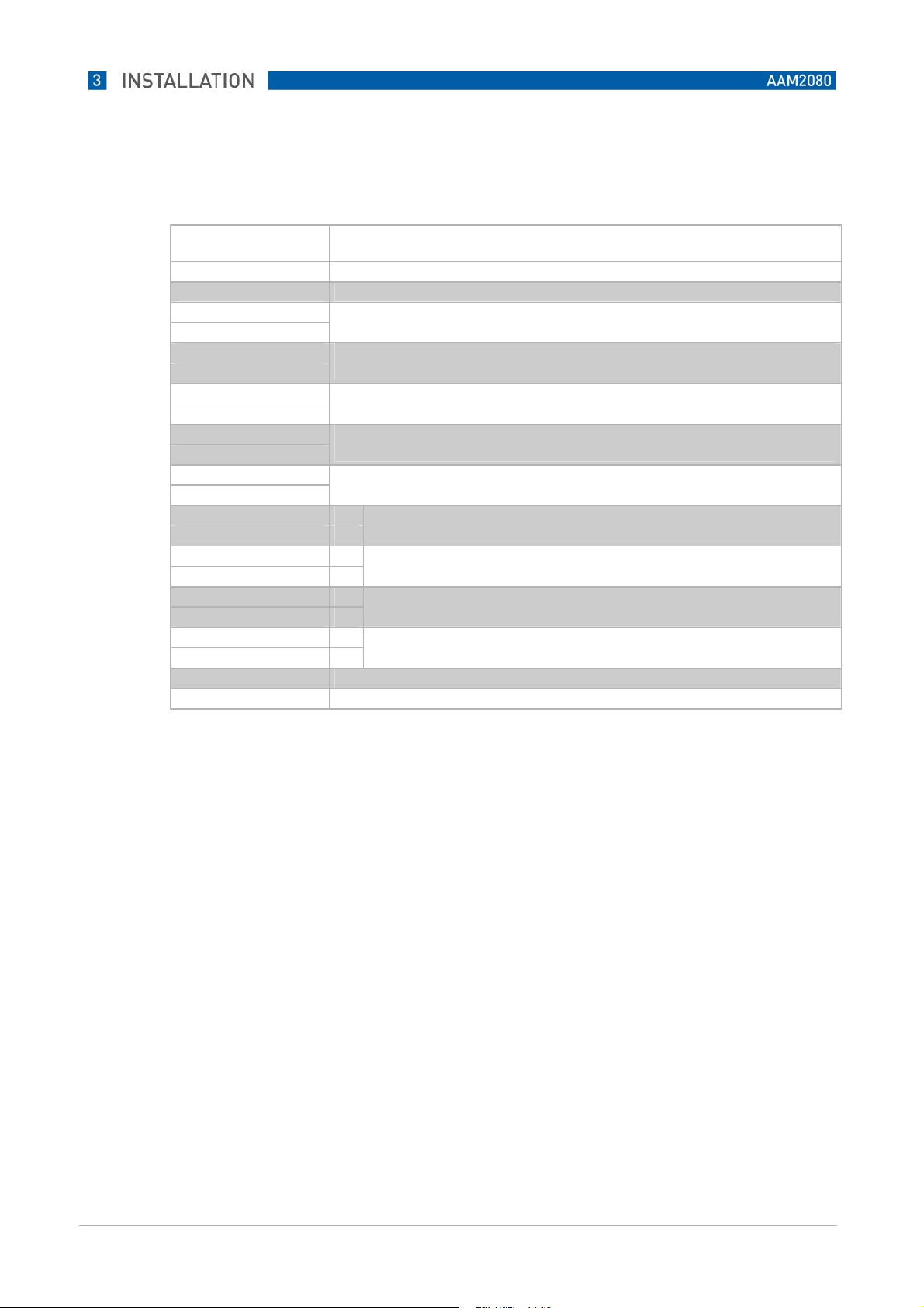
Terminal occupancy
Terminal Function
L ~ Auxiliary power 230 V AC
N ~ Auxiliary power 230 V AC
1
2
3
4
5
6
7
8
9
10
21 +
22 23 +
24 25 +
26 27 +
28 PE Protective conductor (earth/ground)
PE Protective conductor (earth/ground)
K1 Relay 1 max. 230 V AC, 2A
K2 Relay 2 max. 230 V AC, 2A
K3 Relay 3 max. 230 V AC, 2A
K4 Relay 4 max. 230 V AC, 2A
K5 Relay 5 max. 230 V AC, 2A
Analogue output 1 0/4 .. 20 mA
Analogue output 2 0/4 .. 20 mA
Analogue output 3 0/4 .. 20 mA
Analogue output 4 0/4 .. 20 mA
www.krohne.com
13
Page 14

4 Basic Functiions and Start Up
4.1 Front of the converter
2
3
4
5 6
7
8
1
9
“On/Off” switch.
1
Graphical LCD display with background illumination.
2
Menu function button.
3
Call up menu functions, quit menu functions and cancel entries.
Page down individual pages in the menu.
Enter function button.
4
Switch between various displays (retrieval of single channels, hydrographs, etc.), confirm
(acknowledge) entries.
Hold function button.
5
“Maintenance” system setting. The current analogue output signals are frozen (Hold).
Raise values in entry mode.
Measure function button.
6
“Measure” system setting and release of analogue output signals. Lower values in entry mode.
Cal function button.
7
Calls up calibration routines.
Clean function button.
8
Triggers manual cleaning.
Screw connections for power supply, signal lines.
9
Ports for two sensor data lines.
www.krohne.com
14
Page 15

4.2 Measuring channel display
4.3 Plug Connections (Probes)
As standard, two ports (F10) are included on converter PAM2080 for the direct connection of two
measuring probes, for example immersion probe AS75-S4 (see illustration on the right).
Connection to a PAM2080 converter
max. 2 probes directly to the converter
each additional probe via bus distribution boxes
(max. 8 probes on one PAM2080 converter = 8 channels)
Bus connection boxes and extensions for data cables are available as Accessories from KROHNE.
www.krohne.com
15
Page 16
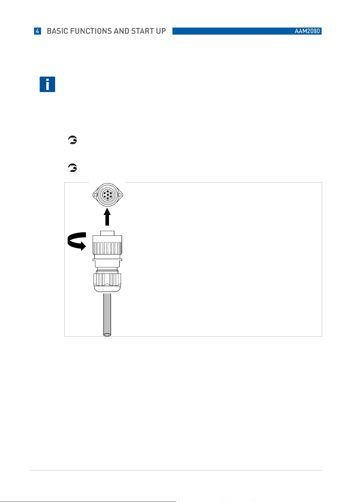
INFORMATION!
The converter recognises all connected probes automatically. You can attach and pin-align the probes at
any port you choose, in any sequence you choose, even during operation. Data transmission between
measuring probes and converter takes place via an internal bus system.
The system's plugs and ports are coded for reverse polarity protection.
Connect the corresponding data cable plugs with the ports on the immersion holder and converter
PAM2080 / bus distribution box.
Always secure the connections by tightening the plug retaining ring.
www.krohne.com
16
Page 17

5 Start Up
5.1 Important information
DANGER!
Carry out the following checks after electrical connection.
Are device or cables externally undamaged?
--
Does the supply voltage match the indications on the type plate?
--
Are electrical / resistance inputs attached and shielded?
--
Are the mounted cables free of strain?
--
Is the cable type guide perfectly separated? Always guide power supply and signal lines separately
--
across the entire the cable route.
Cable guide free of loops and crossovers?
--
Are all screw terminals tightened?
--
Are all cable entry points mounted, tightened and sealed?
--
Are the sensor data cables securely connected to the converter?
--
Is there a cut-off device present?
--
Is the converter made safe with the correct fuse?
--
www.krohne.com
17
Page 18

5.2 Switch On / Off
Switch on converter PAM2080 at the On / Off switch.
The converter runs a self-test for approx. 20 sec. The converter identifies all sensors connected
to the system in the process.
The auto-clean function launches in addition.
The display is inactive during the self-test.
After the self-test, the first channel with its parameters is automatically shown in the display.
NOTE!
The scroll function is active during initial start-up (factory settings). In the process, if several probes are
attached, the converter switches automatically to the next measuring channel every 6 seconds, and so on.
www.krohne.com
18
Page 19

5.3 Change measuring channel display
<
Enter> function button
By pressing Enter you call up attached measuring channels in sequence manually.
The scroll function continues to be active.
The scroll function (alternating channel display) automatically begins again after approx. 60 sec.
inactivity.
You jump to the next measuring channel by pressing Enter again.
www.krohne.com
19
Page 20

5.4 Control button functions
Some of the control buttons have multiple functions,
depending on which area of the operating menu you are currently in .
Button Functions in measuring mode Functions in parameter mode
Retrieval of parameter menus in the respective
measuring channel or data logger area.
Page down individual channels
- Channel 1
- Channel 2
- Channel 3 ..... etc.
- Trendline 1
- Trendline 2
Set system status to “Maintenance”.
Display:
(Signal outputs on Hold.
Automatic rinse function is off.)
Set system status to “Measurement”.
(Signal outputs are released. Automatic rinse
function is active.)
Calibration functions are launched.
Display:
(Signal outputs are frozen according to the set
Hold time.)
Back to measuring mode.
Cancel entries.
Acknowledge entries and jump to
the next point / menu address.
Jump up one address in the menu
field. Increase values on entry.
Jump down one address in the
menu field. Reduce value on entry.
Trigger rinse function manually.
Display:
(Signal outputs are frozen according to the set
Hold time.)
www.krohne.com
20
Page 21

5.5 Menu settings
Converter PAM2080 has various menu and control levels for General Settings, measuring channels and
trend display functions. Most parameters are pre-set factory-side, in order to start up the measuring point
quickly and easily.
For a number of settings you enter alphanumerical values directly.
For other settings you can choose from various functions.
The necessary settings are explained in the following sections.
5.5.1 Parameter-menu
www.krohne.com
21
Page 22

5.5.2 Branching of Parameter menu into further sub-menus
Calibration menu
www.krohne.com
22
Page 23

Sensor data
www.krohne.com
23
Page 24

5.5.3 General Menu
www.krohne.com
24
Page 25

5.5.4 Data logger menu
www.krohne.com
25
Page 26

5.6 Key lock
Converter PAM2080 is equipped with an
automatic key lock in order to prevent unintentional changes to menu settings.
Undo key lock
Hold down Menu button.
Then also press Enter for a few seconds.
A flashing cursor in the first entry row indicates that the key lock has been lifted and changes
are possible.
The keys are automatically locked again after 3 minutes of inactivity.
The lock must be lifted again prior to new changes or entries.
You can undo the key lock as described above at the menu level on every screen.
www.krohne.com
26
Page 27

5.7 The most important settings for a quick start
You can quickly adapt the measuring system to your needs if you pay attention to the small number of
settings described below. All further changes and configurations can be carried out at any time during
ongoing operation.
The measuring system is pre-configured factory-side in accordance with the order data.
Electrode type
Check whether the set electrode type matches the electrode installed in the immersion holder in the
respective measuring channel (= Addr.No.). Pay attention to electrode identification and plug no. (=
Addr.No.). The electrode type (measuring parameter) is displayed top right in the called-up measuring
channel.
Change the electrode type where necessary under "Menu – Sensor data – Electrode".
Measuring range = mA-output
Set the mA range that you need for the respective sensor:
"Menu – Power output – mARange / Start point / Finish point"
Example: Ammonium (NH4-N)
0 .. 20 mA ----- 0 .. 50 mg/l NH4-N
www.krohne.com
27
Page 28

Displaying units
You can select the parameter units.
for pH: pH or mV
for Redox mV or Volt
for ISE connectn. or Atom
(NH4 NH4-N)
"Display – Units"
Auto clean function
If necessary, set the rinse function for immersion holders here. Our recommendation:
Rinse medium Air
Interval: 0,5 hr.
Rinse duration: 4 sec.
Hold time: 30 sec..
Automatic: yes
Rinse medium water
Interval: 2,0 hr.
Rinse duration: 20 sec.
Hold time: 30 sec.
Automatic: yes
"Rinse – Interval / Duration / Hold time / Automatic"
CAUTION!
If you use water as the rinse medium, it is essential that you activate the winter service in addition
(against risk of frost)!
www.krohne.com
28
Page 29

6 Calibration
6.1 Preparation for sensor calibration
To ensure that the measuring system can supply you with correct online data, the installed sensors must
be pre-calibrated.
It is essential that you pay attention to the following information:
Remove all potential protective caps, if present, from the sensors.
In the case of ion-sensitive probes (ISE), check that there are no air bubbles adhering to the inner
side of the membrane. For procedure for removing air bubbles.
Leave the immersion holder with the sensors in the measuring medium for at least one hour before
you commence with a calibration. The sensors need this time in order to get used to the medium
matrix.
We recommend undertaking the following types of calibration:
2-point calibration when:
Starting up for the first time.
--
Changing/regenerating electrodes.
--
Changing the measuring point (≈ change of matrix).
--
Offset calibration:
Regularly during permanent operation depending on electrode drift.
--
www.krohne.com
29
Page 30

6.2 2-Point-Calibration
2-point calibration takes place with two separate measuring solutions (standards) with known
concentrations.
pH- Redox electrodes:
To calibrate pH / Redox electrodes use ready-made standard buffer solutions that can also be procured via
the chemical / laboratory market.
Ion-sensitive probes (ISE):
To calibrate ion-sensitive probes do not use ready-made standard solutions from the laboratory market.
These are of no use for calibration, since as a synthetic measuring solution they never correspond to the
water matrix in which the online measurement is subsequently used. In practice, the resulting calibration
data are only utilisable to a limited extent and may sometimes lead to considerable deviations in
measurement.
Produce your own calibration standards. This is not difficult, but the mistakes described above can be
avoided by doing so. Production of a customised standard solution is described below.
If possible, calibration solutions should be used that are within the prescribed measuring range for online
measuring. The use of concentrations at approx. 10-20% and approx. 80-90% of the expected measuring
range has proved effective (see example).
Example:
0 .. 50 mg/ NO3-N measuring range set on PAM2080 (= mA output)
ca. 5 mg/l NO3-N = 1st standard solution (10% measuring range)
ca. 45 mg/l NO3-N = 2nd standard solution (90% measuring range)
Produce calibration standards with “your” specific water matrix.
For this you use the actual measuring water in which the online measurement is to function later.
www.krohne.com
30
Page 31

6.2.1 Producing calibration standards (ISE)
1st standard (lower concentration) sample volume approx. 800 ml:
Fill a clean vessel (1-ltr. beaker) with approx. 400 ml measuring water.
Dilute with drinking/processing water to approx. 800 ml calibration solution.
For sewage works: optimum dilution water is drained water from final sedimentation.
Determine the precise concentration of the 1st standard solution in the laboratory, please note
measurement.
2nd standard (upper concentration) sample volume approx. 800 ml:
Fill a clean vessel (1-ltr. beaker) with approx. 800 ml measuring water.
Using a suitable standard salt increase the concentration in the sample.
Determine the precise concentration of the 2nd standard solution in the laboratory, please note
measurement.
Where necessary, the mix ratios should be adapted to the optimum measuring range by means of
trials. You can obtain information on suitable standard salts from KROHNE.
www.krohne.com
31
Page 32

6.2.2 Carrying out 2-Point-Calibration
Select the measuring channel that you wish to calibrate.
Set the calibration type to 2-point calibration ("Calibration – Cal.method – 2-Point").
Now enter the determined concentrations (laboratory values) of the calibration solutions / pH buffer
for 1st buffer and 2nd buffer in the Cal menu ("Menu – Cal.menu – 2-Point-Calibration – 1st buffer /
2nd buffer").
Terminate the entry and return from the Cal menu via the parameter menu back to the measurement
display ("Menu – Cal.menu – Menu – Parameter")
Now place the immersion holder with the probe to be calibrated in the 1st calibration standard. First
clean the probe thoroughly using clean water.
The probe/immersion holder should be moved/swung in the calibration solution if possible.
Now press the Hold button on the converter.
Converter goes into system setting “Maintenance”.
Display symbol “Maintenance”.
www.krohne.com
32
Page 33

Now press the Cal button on the converter
Calibration is launched.
“Hold”, “Electrode active”, “Buffer”, “Run time” symbols displayed.
Calibration to the 1st standard lasts approx. 2 minutes. The symbols “Hold” and “Run time”
are displayed after that.
System waits for the 2nd standard.
Now place the immersion holder in the
2nd calibration standard.
First rinse the probe thoroughly again using clean water.
www.krohne.com
33
Page 34

The probe/immersion holder should be moved/swung in the calibration solution again if possible.
Now press the Cal button on the converter again in order to continue calibration.
“Hold”, “Electrode active”, “Buffer”, “Run time” symbols displayed.
Again, calibration to the 2nd standard lasts approx. 2 minutes. The “Hold”, “Electrode”, and
“Run time” symbols are then displayed.
The converter now calculates the calibration curve
The “Hold” symbol is then displayed.
2-point calibration is thereby completed.
To complete, press the “Measure” button in order to delete the hold function. By doing so you
release the analogue output again.
www.krohne.com
34
Page 35

Pay attention to the specific calibration data for this probe
Slope
Offset
www.krohne.com
35
Page 36

6.3 Offset Calibration
Offset calibration is used to compensate for the electrode drift that sets in due to the interaction of the
probes with the measuring medium.
This drift is dependent upon the substances contained in the water and is therefore different for every
measuring point. With time, you will establish how often you need to carry out an offset in each case.
Offset calibration is very easy to carry out. The probe generally remains in the measuring medium in the
process.
Carrying Out Offset Calibration
Select the measuring channel that you wish to calibrate.
Set the calibration type to offset calibration ("Calibration – Cal.method – Offset). Ensure that
measurement is active (must not remain on “Hold”).
Now press the Cal button once.
Displays of “Hold”, “Electrode active”, “Buffer”, “Run time” indicate that the offset routine is
running.
The symbols “Hold”, “Buffer” and “Run time” are displayed after approx. 20 sec.
Now press the Cal button once more in order to save the determined measurement internally.
You now have 2 hours.
www.krohne.com
36
Page 37

The current measurement is saved by the converter as “Redox voltage” for the next 2 hours.
Offset calibration must be completed within this period, otherwise the entire process will be
cancelled. The converter will then continue to work with the former calibration data.
Now take a medium sample close to the probe. Determine the concentration of the sample
(laboratory).
The converter continues to work as normal in the meantime.
Enter the determined laboratory value of the sample in the measuring converter as “current
value” ("Calibration – current value").
Then press the Cal button on the converter again in order to continue / complete the calibration.
The symbols “Hold”, “Electrode active”, “Buffer”, “Run time” are displayed.
The “laboratory value” is adopted and a curve adaptation is recalculated by the converter using
the saved internal “Redox value”.
The symbols “Hold”, “Electrode” and “Run time” are displayed.
The symbols disappear after a few seconds and measurement is in the active measuring mode
with new offset of the concentration curve.
www.krohne.com
37
Page 38

NOTE ON PH / REDOX MEASUREMENT
You can carry out offset calibration with total ease with both ISE probes and pH / Redox probes.
Proceed as described above. Measure the pH value of the measuring medium using a comparison pH
measurement (manual pH meter) and enter the pH value under Buffer 1.
www.krohne.com
38
Page 39

6.4 General settings
Enter the menu-button to make the general settings.
General Data
Designation Settings Description
Scroll time
Modifications
Parameters
00.0 – 99.9 min
permitted
blocked
save data
load data
Normal
Hold
Reset
Default
Automatic display-switching between measuring channels.
00.0 min = no scroll function
Permitted: Entries and modifications are possible.
Blocked: Entries and modifications are not possible.
save data: Saves the current general settings in EEPROM.
load data: Loads and uses the last saved settings
Normal Standard setting. Relay contacts are active as long as thresholds
are exceeded.
Hold Relay contacts are active, but are held even if thresholds are no
longer exceeded.
Reset using the Measure button.
Reset The converter carries out a new system start.
All set data are retained
Default The converter carries out a new system start. All data set by the
user are reset to factory settings.
Relay-Output
Designation Settings Description
Inverted
Switching contacts
Relay No. 1
Switching contacts
Relay No. 2
00000 11111
00 – 16 Pre-alert 00 = not active
00 – 16 Pre-alert 00 = not active
The switching contacts for the respective relay can be set as follows
0 = close actively (idle current, relay open as normal)
1 = open actively (operating current, relay closed as normal)
Relay allocation:
0 0 0 0 0
Relay 1
Relay2
Relay 3
Relay 4
Relay 5
01 = active on measuring channel 1
02 = active on measuring channel 2
03 = active on measuring channel 3
and so on
Alert Setting possibilities as with pre-alert
Fault Setting possibilities as with pre-alert
01 = active on measuring channel 1
02 = active on measuring channel 2
03 = active on measuring 3
and so on
Alert Setting possibilities as with pre-alert
Fault Setting possibilities as with pre-alert
www.krohne.com
39
Page 40

Switching contact
Relay No. 3
Switching contact
Relay No. 4
Switching contact
Relay No. 5
00 – 16
00 – 16
00 – 16
Pre-alert 00 = not active
01 = active on measuring channel 1
02 = active on measuring channel 2
03 = active on measuring channel 3
and so on
Alert Setting possibilities as with pre-alert
Fault Setting possibilities as with pre-alert
Pre-alert 00 = not active
01 = active on measuring channel 1
02 = active on measuring channel 2
03 = active on measuring channel 3
and so on
Alert Setting possibilities as with pre-alert
Fault Setting possibilities as with pre-alert
Pre-alert 00 = not active
01 = active on measuring channel 1
02 = active on measuring channel 2
03 = active on measuring channel 3
and so on
Alert Setting possibilities as with pre-alert
Fault Setting possibilities as with pre-alert
The relays can be freely programmed individually or in combinations. In the process only one alert status
can be allocated to each relay (lower alert threshold or upper alert threshold or technical fault). Incorrect
or duplicated allocations can lead to measuring converter malfunction.
www.krohne.com
40
Page 41

Date and time
Designation Settings Description
Date
Time
01.01.04 –
31.12.99
00:00 – 23:59 Time entry / modification if required. Automatic adjustment from standard time (GMT
Date entry / modification if required
(+1)) to summer time (GMT+1 (+2)) does not take place.
www.krohne.com
41
Page 42

6.5 Hydrograph Menu
Hydrographs and data loggers
Designation Settings Description
Status curve
Number windows
Resolution 00.02 – 99.00
Time range 00.1 – 99.9 h Adjustable time for the visible time window of the status curve. Recommendation:
Yes
No
00 – 03
min.
Yes
The measurement is shown additionally as a trend curve in the field beneath the
temperature display in the normal display screen of a measuring channel.
The display range corresponds to the set range of the mA power output.
No
Depiction of the hydrograph in the measuring channel display screen is switched off.
Indicates the number of hydrograph windows (data logger function). A maximum of 3
windows can be activated.
Time interval during which the measurements are depicted in the status curve in
updated form.
24.0 h
Calibration of analogue outputs
Designation Settings Description
Channel number 01 – 08 Selection of the channel in which the analogue output is to be tested / calibrated.
Simulation 00 – 20 mA Entry of a power value which is then present at the corresponding terminals of the
Power value 00 – 20 mA Entry of the power value actually arriving at the end of the signal line when a
respective channel.
Ideal for simple testing of signal lines from the converter to analogue value recorders.
simulated current value has been preset.
The converter automatically corrects the analogue output based on the entry.
This way you can easily compensate for signal deviations/losses of current in signal
lines.
www.krohne.com
42
Page 43

Fixed allocations of analogue outputs
Designation Settings Description
Parameters 00:00:00:00 Allocation of 4 of the maximum 8 possible measuring channels (01 – 08) to the 4
mA outputs 00:00:00:00 Free allocation of analogue outputs 01-04 to the measuring channel defined above
Baud rate RS232 02400
04800
09600
19200
38400
Baud rate RS422 02400
04800
09600
19200
38400
analogue outputs. Attention, no channel may be indicated multiple times.
Factory setting 09600 baud.
Setting for data transmission between converter and PC. If possible, do not change the
baud rate on the converter.
If necessary, change the baud rate on your PC to the same baud rate as the converter.
Factory setting 19200 baud.
Setting for data transmission between converter and probe.
Do not change the baud rate, otherwise communication between converter and probe
may be disrupted.
In the case of doubt speak to the KROHNE service department beforehand.
www.krohne.com
43
Page 44

6.6 Channel-specific settings
This menu is the same for every measuring channel.
You must undertake specific parameter changes for every measuring channel separately.
Measuring point name
Designation Settings Description
Addr: 01 NAM760-
BDS
1. Title
The name of the measuring point or another designation can be entered here. The
following ASCII symbols are available to you.
! „ # $ % & ´ ( ) * + , - .
/ 0 1 2 3 4 5 6 7 8 9 : ; < =
> ? A B C D E F G H I J K L M
N O P Q R S T U V W X Y Z a b
c d e f g h i j k l m n o p q
r s t u v w x y z
www.krohne.com
44
Page 45

Sensor data - setting of sensor type
Designation Settings Description
Slope xxx.x %
0.00 – 100 %
Offset +- x.xx pX
- 9.99 - + 9.99
pX
Electrode Gas sensor
pH-Type
Ammoniac
Ammonium
Nitrate
Potassium
Calcium
Sulfite
Cyanide
Chloride
Fluoride
Sodium
Bromide
Nitrite
Redox
Oxygen
Chlorine
Phosphate
Lithium
Refraction
Lead
Sulfide
Sulfide-H
Sulfide-H2
Zero line 000.0 ppm Lower sensor-specific sensitivity threshold. This value is a component of the factory
Displays the dynamic sensor slope. The value changes depending on the calibration
data and sensor duration of operation.
Manual correction of the value is generally not necessary.
Please ask for details at the KROHNE service department covering your area.
Displays the dynamic sensor zero point. The value changes depending on the
calibration and sensor duration of operation.
Manual correction of the value is generally not necessary.
Please ask for details at the KROHNE service department covering your area.
Sensor type that is recognised by the converter.
The new sensor type must be selected here if the sensor is changed on the respective
measuring channel.
Depending on sensor type the corresponding factory setting is retrieved with the
specific sensor data.
Further sensor types on request.
calibration. Modifications only after consultation with KROHNE-System service
department.
Sensor calibration
Designation Settings Description
Current value 00.00 ppm Displays the last current calibration value.
Cal. method Offset
2-point
StdAdd.
C-curve
Entry of the offset value for offset calibration here. See also offset calibration
Opportunity to select calibration routines. See calibration menu for further details.
Offset
1-point adaptation of an available calibration curve in order to compensate for drift
deviations.
2-point
Calibration method via 2 standard solutions.
Std.Add.
Calibration routine via a standard addition (optional).
C-curve
Calibration by creating a concentration curve (optional).
www.krohne.com
45
Page 46

General settings for sensor
Designation Settings Description
Start position Measurement
Maintenance
Check type Off
Normal
Moderate
Strict
Zero balance Manual
Automatic
Indicates in which mode the converter is to switch following start-up / Power on.
Measurement
The converter switches to measuring mode. The analogue outputs are active.
Maintenance
The converter remains in maintenance mode, the analogue outputs are switched to
Hold.
Manual release by pressing the Measurement button on the converter is necessary.
Indicates under which criteria the functionality of the electrodes is to be monitored.
Off
Electrode monitoring only during calibration.
Normal
Constant checking using standard tolerances.
Moderate
Constant checking using tight tolerances.
Strict
Constant checking using minimum tolerances.
Recommend setting in standard applications: "Off".
Manual
Null balance occurs during the next calibration in each case. Specifically for large
measuring ranges. This setting is used in the normal case.
Automatic
For use when measuring is undertaken consistently in the lower measuring range. Null
balance then occurs internally. Increases precision in the lower measuring range.
Setting analogue outputs
Designation Settings Description
mA range 0 .. 20 mA
4 .. 20 mA
Start point 000.0 ppm Enter the start concentration for 0 or 4 mA
Finish point 000.0 ppm Enter the finish concentration for 20 mA
Set the type of analogue signals here
Setting threshholds (relay control)
Designation Settings Description
Pre-alert 000.0 ppm The pre-alert is triggered if values are exceeded. Set relays are activated.
Alert 000.0 ppm The alert is triggered if values are exceeded. Set relays are activated
Hysteresis 000.0 ppm Adjustable switching threshold
Delay 000.0 min Adjustable time by which an alert trigger can be delayed.
www.krohne.com
46
Page 47

Settings for the display
Designation Settings Description
Units lin
log
mV
pH
%
Modify permitted
blocked
save data
load data
System Reset
Default
Test
Zero point 000.0 ppm Measurements beneath this adjustable value are displayed with this value.
The selection possibilities depend on the respective parameter. The reference
magnitude between molecule or element can also be chosen during ISE measurement.
permitted
Entries and modifications are possible for this channel.
blocked
Entries and modifications are not possible
save data
Saves the current measuring channel settings.
load data
loads and uses the last saved channel settings.
Reset
The converter is restarted with the currently used parameters
Default
The converter is restarted with the factory settings. Existing customised settings are
lost.
Test
The converter switches to a test mode. Use this setting only in consultation with
KROHNE service.
Settings for auto-clean function
Designation Settings Description
Interval 000.0 h Entry at which time intervals the auto-clean function is to be activated.
Duration 000 sec Rinse duration in seconds
Hold time 000 sec Waiting period after rinsing after which measurement can be engaged again. The
Automatic Yes
No
Recommendation: 000.5 h for compressed air, 002.0 h for water
Recommendation: 005 sec. for compressed air, 020 sec. for water
analogue outputs are frozen during the hold time. Recommendation: 030 sec.
Yes The auto-clean function is active
No The auto-clean function is not active.
www.krohne.com
47
Page 48

Settings for auto-clean function winter service (necessary when rinsing with water)
Designation Settings Description
Interval
Duration
Hold time
Temperature 008 °C Limit temperature for winter service program.
Automatic Yes
000.0 h
000 sec
000 sec
No
Entry at which time intervals the auto-clean function is to be activated.
Recommendation: 000.2 h
Rinse duration in seconds
Recommendation: 002 sec.
Waiting period after rinsing after which measurement can be engaged again. The
analogue outputs are frozen during the hold time.
Yes The auto-clean function is active
No The auto-clean function is not active.
Switch to other menu levels
Designation Settings Description
Menu MainMnu
CalMnu
SensorMnu
MainMnu Return to the main menu
CalMnu Call up the calibration menu
SensorMnu Call up the specific sensor menu
www.krohne.com
48
Page 49

6.7 Calibration submenu
You set the specific parameters for the calibration routines in this menu.
You get to the calibration submenu via the measuring channel menu.
Entering current value for offset calibration
Designation Settings Description
Current pt 00.00 ppm Entry of the laboratory value for offset calibration
Settings for standard addition (optional)
Designation Settings Description
Sample volume 10.00 lt Pre-set volume in which calibration is carried out following standard addition.
Flow 000.02 ml Inflow rate of the standard calibration solution
Standard 0.000 M/l Concentration of the standard in Mol/l
No. steps 03 step Enter number of steps with which the standard addition is to be implemented.
2-point calibration: Entering the concentrations of the standard solutions
Designation Settings Description
1st buffer 000.0 ppm Entry of the concentration of the first calibration standard (low concentration)
2nd buffer 000.0 ppm Entry of the concentration of the second calibration standard (higher concentration)
www.krohne.com
49
Page 50

Compensation of constant disturbances (manual correction of cross-sensitivities )
Designation Settings Description
Correction value +- 00.0 ppm Here you can manually undertake compensations if disturbing ions disturb the
measurement by a constant amount.
Set a fixed correction value that is added to the measurement (+) or deducted from the
measurement (-).
After entering the correction value you must carry out an offset calibration using the
medium’s current measurement (measurement prior to entry of the correction value).
Calibrating the temperature sensor
Designation Settings Description
Temperature 025.0 °C If the temperature sensor does not display the correct temperature, the temperature can
be calibrated here.
Implementation: enter the current temperature and then press Enter. Switch briefly into
display mode. Switch back to the menu and enter the same temperature once again.
Press Enter. The calibration temperature is saved.
Settings for calibration with standard addition (optional) only on Analyser DISCO-2
Designation Settings Description
Pump duration 00.1 min Pump duration of a metering pump
Cond. volume 0.000 lt Volume of conditioning medium which is to be set
Automatic No
Yes
Valve number 000 Sets which valve is to be controlled during standard addition
No
Manual activation of the standard addition
Yes
Automatic activation of the standard addition
Back to measuring mode
Designation Settings Description
Menu Parameters
Default
Parameters
Return to the measuring channel menu
Default
Restart with factory settings
The parameters used up to now are deleted.
www.krohne.com
50
Page 51

6.8 Sensor date submenu
In the sensor data submenu you have the opportunity to activate sensor-specific functions. You can offset
various sensors with one another and thus actively reduce cross-sensitivities from unknown ions.
You get to the sensor data submenu via the measuring channel menu.
Settings for disturbing ion compensation
Designation Settings Description
Channel number 00 Set the other channel that is to be used for compensation here.
Coefficient -9.99 - +9.99 Offsetting factor by which the cross-sensitivity in respect of counter-ions is to be
Addition Yes
No
compensated. Please ask KROHNE for the specific values.
Yes
Activation of compensation
No
Deactivation of compensation
Electrode specification (factory setting)
Designation Settings Description
Inner buffer +- 000 mV Sensor-specific features. Loaded on retrieval of the sensor. Please do not change the
Norm-Offset +- 0.00 pX Sensor-specific features. Loaded on retrieval of the sensor. Please do not change the
factory setting.
factory setting.
www.krohne.com
51
Page 52

Damping the analogue output
Designation Settings Description
Averaging above 000 –100
points
mA simulation 00.00 – 20.00
mA
Designation Settings Description
Disp. parameters 00 Number of parameters that are attached to the converter.
Base address 01 – 08 The address that is allocated to the parameter. The address can be changed if
Second title If required, enter an additional title for the parameter here.
Option for averaging analogue output.
This value is issued at the analogue output after a power value is entered.
necessary.
Pay attention that no sensor has the same base address. Otherwise the converter cannot
communicate with the sensors without problems.
www.krohne.com
52
Page 53

6.9 Data logger settings
If one or more data logger windows were activated in the general cross-channel settings,
you have the opportunity to configure the hydrograph screens.
You can depict up to 3 measuring channels simultaneously per screen.
Use Enter to call up the respective hydrograph screen.
Use Menu to call up the data logger settings:
Designation Settings Description
Hydrograph
Range 000.1 – 999.9 h Establishes the range to be depicted
Scale 000.1 – 999.9 h Establishes the scale with time and date display
1st curve
Address 01 – 08 Selection of the channel that is to be displayed in this screen.
Title Indicate a title for the channel here
Start 000.0 ppm Measuring range start that is to be depicted
Finish 000.0 ppm Measuring range finish that is to be depicted
2nd curve
Address 01 – 08 Selection of the channel that is to be displayed in this screen.
Title Indicate a title for the channel here
Start 000.0 ppm Measuring range start that is to be depicted
Finish 000.0 ppm Measuring range finish that is to be depicted
3rd curve
Address 01 – 08 Selection of the channel which is to be displayed in this screen.
Title Indicate a title for the channel here
Start 000.0 ppm Measuring range start that is to be depicted
Finish 000.0 ppm Measuring range finish that is to be depicted
www.krohne.com
53
Page 54

KROHNE as vendor, warrants to the original purchaser of this instrument that it will be free of defects in
material and workmanship, in normal use and service, for a period of one year from date of delivery to the
original purchaser. KROHNE’s, obligation under this warranty is limited to replacing, at its factory, the
instrument or any part thereof. Parts, which by their nature are normally required to be replaced
periodically, consistent with normal maintenance, specifically reagent, desiccant, sensors, electrodes and
fuses are excluded. Also exclud¬ed are accessories and supply type items.
Original purchaser is responsible for return of the instruments, or parts thereof, to KROHNE. This
includes all freight charges incurred in shipping to and from KROHNE sales organization.
KROHNE is not responsible for damage to the instrument, or parts thereof, resulting from misuse,
environmental corrosion, negligence or accident, or defects resulting from repairs, alterations or
installation made by any person or company not authorized by KROHNE.
KROHNE assumes no liability for consequential damage of any kind, and the original purchaser, by
placement of any order for the instrument, or parts thereof, shall be deemed liable for any and all damages
incurred by the use or misuse of the instruments, or parts thereof, by the purchaser, its employees, or
others, following receipt thereof.
Carefully inspect this product for shipping damage, if damaged, immediately notify the shipping company
and arrange an on-site inspection. KROHNE cannot be responsible for damage in shipment and cannot
assist with claims without an on-site inspection of the damage.
This warranty is given expressly and in lieu of all other warran¬ties, expressed or implied. Purchaser
agrees that there is no warranty on merchantability and that there are no other warranties, ex¬pressed or
implied. No agent is authorized to assume for KROHNE any liability except as set forth above.
Please include the following return template with your instrument.
www.krohne.com
54
Page 55

Device Return Template:
This device has been carefully manufactured and tested. If
installed and operated in accordance with these operating
instructions, it will rarely present any problems. Should you
nevertheless need to return a device for inspection or repair,
please pay strict attention to the following points:
Due to statutory regulations on environmental protection and
safeguarding the health and safety of our personnel,
KROHNE may only handle, test and repair returned devices
that have been in contact with products without risk to
personnel and environment.
This means that KROHNE can only service this device if it
is accompanied by the following certificate confirming that
the device is safe to handle.
S P E C I M E N certificate
Company:………………………………………………. Address:……………………………………………
Department:…………………………………………… Name:……………………………………………
Tel. No.:……………………………………………….. Fax
Email:…………………………………………………...
The enclosed device
Type:…………………………………………………………………………………………………………………
…………
KROHNE Order No. or Series No.:……………………………………………………………………..
has been operated with the following
liquid:……………………………………………………………………………….
Because this liquid is
water-hazardous toxic caustic.. flammable
we have
checked that all cavities in the device are free from such substances
flushed out and neutralized all cavities in the device
We confirm that there is no risk to humans or environment through any residual liquid contained in this device.
If the device has been operated with toxic, caustic,
flammable or water-endangering products, you are
kindly requested:
• to check and ensure, if necessary by rinsing or
neutralizing, that all cavities are free from such
dangerous substances,
• to enclose a certificate with the device
confirming that is safe to handle and stating the
product used.
We cannot service this device unless accompanied
by such a form.
……
………
No.:…………………………………………….......
.
www.krohne.com
55
 Loading...