

Page 1
Handbook
Handbook
OPTIBAR P 3050 C
OPTIBAR P 3050 C
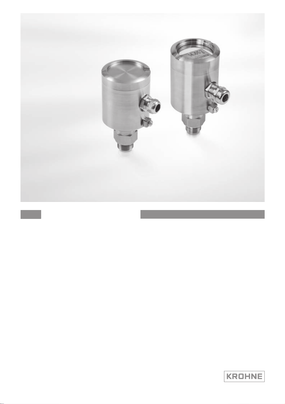
OPTIBAR P 3050 COPTIBAR P 3050 C
Compact pressure transmitter with recessed
diaphragm
HandbookHandbook
© KROHNE 03/2012 - 4001953401 - MA OPTIBAR P3050C R02 en
Page 2

: IMPRINT :::::::::::::::::::::::::::::::::::::::
All rights reserved. It is prohibited to reproduce this documentation, or any part thereof, without
the prior written authorisation of KROHNE Messtechnik GmbH.
Subject to change without notice.
Copyright 2012 by
KROHNE Messtechnik GmbH - Ludwig-Krohne-Str. 5 - 47058 Duisburg (Germany)
2
www.krohne.com 03/2012 - 4001953401 - MA OPTIBAR P3050C R02 en
Page 3

OPTIBAR P 3050 C
CONTENTS
1 Safety instructions 5
1.1 Intended use ..................................................................................................................... 5
1.2 Technical limits ................................................................................................................ 6
1.3 Permissible products .......................................................................................................6
1.4 Certification ...................................................................................................................... 6
1.5 Safety instructions from the manufacturer ..................................................................... 7
1.5.1 Copyright and data protection ................................................................................................ 7
1.5.2 Disclaimer ............................................................................................................................... 7
1.5.3 Product liability and warranty ................................................................................................ 8
1.5.4 Information concerning the documentation........................................................................... 8
1.5.5 Warnings and symbols used................................................................................................... 9
1.6 Safety instructions for the operator................................................................................. 9
2 Device description 10
2.1 Scope of delivery............................................................................................................. 10
2.2 Device description .......................................................................................................... 11
2.2.1 Device design ........................................................................................................................ 12
2.2.2 Process connection variants................................................................................................. 12
2.3 Nameplates .................................................................................................................... 13
3 Installation 14
3.1 Notes on installation ......................................................................................................14
3.2 Storage ........................................................................................................................... 14
3.3 Transport ........................................................................................................................ 14
3.4 Installation specifications .............................................................................................. 14
3.5 Installation...................................................................................................................... 15
3.5.1 Sealing and screwing-in .......................................................................................................15
3.5.2 Humidity ................................................................................................................................ 15
3.5.3 Pressure connection via impulse line .................................................................................. 16
3.5.4 Opening the device, installing and dismantling the graphic display ................................... 16
3.6 Ventilating the pressure sensor..................................................................................... 17
4 Electrical connections 18
4.1 Safety instructions.......................................................................................................... 18
4.2 Notes for electrical cables ............................................................................................. 18
4.2.1 Requirements for signal cables provided by the customer ................................................. 19
4.2.2 Laying electrical cables correctly......................................................................................... 19
4.2.3 Connection to the feed unit................................................................................................... 20
4.3 Electrical connection......................................................................................................20
4.3.1 Tailoring the cables .............................................................................................................. 20
4.3.2 Connection in the terminal compartment ............................................................................ 21
4.4 Grounding the measuring device ................................................................................... 22
4.5 Description of the current output................................................................................... 22
www.krohne.com03/2012 - 4001953401 - MA OPTIBAR P3050C R02 en
3
Page 4

CONTENTS
OPTIBAR P 3050 C
5 Operation 23
5.1 Start-up........................................................................................................................... 23
5.2 Factory settings and settings during reset.................................................................... 23
5.3 General setting options .................................................................................................. 24
5.4 Setting the blind device .................................................................................................. 24
5.4.1 Position correction................................................................................................................ 24
5.4.2 Zero point and span start (4 mA) ..........................................................................................24
5.4.3 Span end (20 mA) .................................................................................................................. 25
5.4.4 Factory reset ......................................................................................................................... 25
5.5 Setting the version with display ..................................................................................... 25
5.5.1 Display and operating elements...........................................................................................25
5.5.2 Structure of the operating menu..........................................................................................27
5.5.3 Description of the function ................................................................................................... 28
6 Service 30
6.1 Replacing the pressure sensor, the electronics and the display .................................. 30
6.2 Spare parts availability...................................................................................................31
6.3 Availability of services .................................................................................................... 31
6.4 Repairs............................................................................................................................ 31
6.5 Returning the device to the manufacturer..................................................................... 32
6.5.1 General information.............................................................................................................. 32
6.5.2 Form (for copying) to accompany a returned device............................................................ 33
6.6 Disposal .......................................................................................................................... 33
7 Technical data 34
7.1 Measuring principle........................................................................................................34
7.2 Technical data................................................................................................................. 36
7.3 Pressure ranges............................................................................................................. 38
7.4 Dimensions and weights ................................................................................................ 39
4
www.krohne.com 03/2012 - 4001953401 - MA OPTIBAR P3050C R02 en
Page 5
OPTIBAR P 3050 C
1.1 Intended use
CAUTION!
Responsibility for the use of the measuring devices with regard to suitability, intended use and
corrosion resistance of the used materials against the measured fluid lies solely with the
operator.
INFORMATION!
The manufacturer is not liable for any damage resulting from improper use or use for other than
the intended purpose.
SAFETY INSTRUCTIONS 1
The pressure transmitter series OPTIBAR
absolute and gauge pressure of gases, vapours and liquids. The available measuring ranges and
permitted maximum working pressures for each are indicated on the nameplate and described
in the "Technical data" section. To observe the intended use, adhere to the following points:
• Observe the instructions in this document.
• Comply with the technical specifications (for details refer to
• Observe the permissible products (for details refer to
• Only suitably qualified personnel may install and operate the device.
• Observe the generally accepted standards of good practice.
OPTIBAR were designed and constructed to measure the
OPTIBAROPTIBAR
Technical limits
Permissible products
on page 6).
on page 6).
CAUTION!
•
Any modification to the device, including drilling, sawing, trimming, welding and soldering of
parts, or partially painting over or coating, is prohibited.
•
Neither is it permitted to use the device as a climbing aid e.g. for installation purposes, as a
holder for cables, pipes or other loads.
•
The mounting or installation of parts is only permitted as described in this document, or
insofar as it has been authorised by the manufacturer or a certified service partner.
DANGER!
For devices used in hazardous areas, additional safety notes apply; please refer to the Ex
documentation.
www.krohne.com03/2012 - 4001953401 - MA OPTIBAR P3050C R02 en
5
Page 6

1 SAFETY INSTRUCTIONS
1.2 Technical limits
The device was constructed solely for use within the technical limits indicated on the nameplate
and in the technical data. Applications outside of these limits are not permitted and could lead to
significant risk of accident. For this reason, observe the following limits:
• Do not exceed or go below the maximum permissible pressure or vacuum.
• Do not exceed or go below the indicated permissible operating temperature range.
• Do not exceed or go below the indicated permissible ambient temperature.
• Observe the housing protection type during use (IP67 only with internally ventilated cable!).
1.3 Permissible products
The device is designed to measure the pressure of vaporous, gaseous and liquid media. Device
variants featuring recessed diaphragms are not suitable for the measurement of products
containing solids or viscous and paste-like products. Prior to using any corrosive or abrasive
products, the operator must check the resistance of all parts in contact with the product.
OPTIBAR P 3050 C
1.4 Certification
CE marking
The device fulfils the statutory requirements of the following EC directives:
• Low Voltage Directive 2006/95/EC
• EMC directive 2004/108/EC
• EMC specification acc. to EN 61326/A1
The manufacturer certifies successful testing of the product by applying the CE mark.
Pressure Equipment Directive PED
Devices with a permissible pressure PS ≤ 200 bar (20 MPa) comply with Article 3 Section (3) and
were not subject to a conformity assessment. These devices were designed and manufactured in
accordance with sound engineering practice (SEP).
The CE marking on the device does not apply to the Pressure Equipment Directive.
DANGER!
For devices used in hazardous areas, additional safety notes apply; please refer to the Ex
documentation.
6
www.krohne.com 03/2012 - 4001953401 - MA OPTIBAR P3050C R02 en
Page 7

OPTIBAR P 3050 C
1.5 Safety instructions from the manufacturer
1.5.1 Copyright and data protection
The contents of this document have been created with great care. Nevertheless, we provide no
guarantee that the contents are correct, complete or up-to-date.
The contents and works in this document are subject to copyright. Contributions from third
parties are identified as such. Reproduction, processing, dissemination and any type of use
beyond what is permitted under copyright requires written authorisation from the respective
author and/or the manufacturer.
The manufacturer tries always to observe the copyrights of others, and to draw on works created
in-house or works in the public domain.
The collection of personal data (such as names, street addresses or e-mail addresses) in the
manufacturer's documents is always on a voluntary basis whenever possible. Whenever
feasible, it is always possible to make use of the offerings and services without providing any
personal data.
SAFETY INSTRUCTIONS 1
We draw your attention to the fact that data transmission over the Internet (e.g. when
communicating by e-mail) may involve gaps in security. It is not possible to protect such data
completely against access by third parties.
We hereby expressly prohibit the use of the contact data published as part of our duty to publish
an imprint for the purpose of sending us any advertising or informational materials that we have
not expressly requested.
1.5.2 Disclaimer
The manufacturer will not be liable for any damage of any kind by using its product, including,
but not limited to direct, indirect or incidental and consequential damages.
This disclaimer does not apply in case the manufacturer has acted on purpose or with gross
negligence. In the event any applicable law does not allow such limitations on implied warranties
or the exclusion of limitation of certain damages, you may, if such law applies to you, not be
subject to some or all of the above disclaimer, exclusions or limitations.
Any product purchased from the manufacturer is warranted in accordance with the relevant
product documentation and our Terms and Conditions of Sale.
The manufacturer reserves the right to alter the content of its documents, including this
disclaimer in any way, at any time, for any reason, without prior notification, and will not be liable
in any way for possible consequences of such changes.
www.krohne.com03/2012 - 4001953401 - MA OPTIBAR P3050C R02 en
7
Page 8

1 SAFETY INSTRUCTIONS
1.5.3 Product liability and warranty
The operator shall bear responsibility for the suitability of the device for the specific purpose.
The manufacturer accepts no liability for the consequences of misuse by the operator. Improper
installation and operation of the devices (systems) will cause the warranty to be void. The
respective "Standard Terms and Conditions" which form the basis for the sales contract shall
also apply.
1.5.4 Information concerning the documentation
To prevent any injury to the user or damage to the device it is essential that you read the
information in this document and observe applicable national standards, safety requirements
and accident prevention regulations.
If this document is not in your native language and if you have any problems understanding the
text, we advise you to contact your local office for assistance. The manufacturer can not accept
responsibility for any damage or injury caused by misunderstanding of the information in this
document.
This document is provided to help you establish operating conditions, which will permit safe and
efficient use of this device. Special considerations and precautions are also described in the
document, which appear in the form of underneath icons.
OPTIBAR P 3050 C
8
www.krohne.com 03/2012 - 4001953401 - MA OPTIBAR P3050C R02 en
Page 9
OPTIBAR P 3050 C
1.5.5 Warnings and symbols used
Safety warnings are indicated by the following symbols.
DANGER!
This information refers to the immediate danger when working with electricity.
DANGER!
This warning refers to the immediate danger of burns caused by heat or hot surfaces.
DANGER!
This warning refers to the immediate danger when using this device in a hazardous atmosphere.
DANGER!
These warnings must be observed without fail. Even partial disregard of this warning can lead to
serious health problems and even death. There is also the risk of seriously damaging the device
or parts of the operator's plant.
SAFETY INSTRUCTIONS 1
WARNING!
Disregarding this safety warning, even if only in part, poses the risk of serious health problems.
There is also the risk of damaging the device or parts of the operator's plant.
CAUTION!
Disregarding these instructions can result in damage to the device or to parts of the operator's
plant.
INFORMATION!
These instructions contain important information for the handling of the device.
LEGAL NOTICE!
This note contains information on statutory directives and standards.
• HANDLING
HANDLING
HANDLINGHANDLING
This symbol designates all instructions for actions to be carried out by the operator in the
specified sequence.
i RESULT
RESULT
RESULTRESULT
This symbol refers to all important consequences of the previous actions.
1.6 Safety instructions for the operator
WARNING!
In general, devices from the manufacturer may only be installed, commissioned, operated and
maintained by properly trained and authorized personnel.
This document is provided to help you establish operating conditions, which will permit safe and
efficient use of this device.
www.krohne.com03/2012 - 4001953401 - MA OPTIBAR P3050C R02 en
9
Page 10
2 DEVICE DESCRIPTION
2.1 Scope of delivery
INFORMATION!
Inspect the cartons carefully for damages or signs of rough handling. Report damage to the
carrier and to the local office of the manufacturer.
INFORMATION!
Do a check of the packing list to make sure that you have all the elements given in the order.
INFORMATION!
Look at the device nameplate to ensure that the device is delivered according to your order.
Check for the correct supply voltage printed on the nameplate.
OPTIBAR P 3050 C
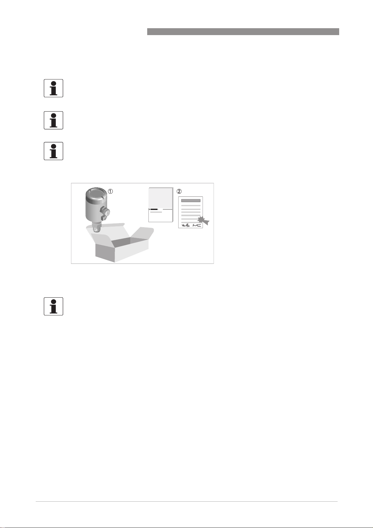
Figure 2-1: Scope of delivery
1 Device in the version as ordered.
2 Documentation (calibration protocol, factory and material certification (if ordered) and product documentation)
INFORMATION!
Assembly materials and tools are not part of the delivery. Use the assembly materials and tools
in compliance with the applicable occupational health and safety directives.
10
www.krohne.com 03/2012 - 4001953401 - MA OPTIBAR P3050C R02 en
Page 11

OPTIBAR P 3050 C
2.2 Device description
The pressure gauges are designed solely for the direct measurement of process pressures and
indirect level measurement in straight, symmetrical tanks. In addition to the main measuring
parameters, it is also possible to measure the sensor temperature.
The device can be operated "on site" using a push button on the converter electronics (zero
point, measurement span start and span end) or using the optionally available LCD display with
four push buttons.
Depending on the measuring range and overload resistance, piezoresistive or thin film sensors
may be used. The pressure is transmitted either directly or by way of a separating diaphragm
and a liquid fill to a measuring diaphragm, which then distorts and reverses under the applied
pressure. The measuring diaphragm features RTDs that change their resistance value based on
the mechanical distortion, enabling the applied pressure to be inferred.
Communication takes place via an analogue 4...20 mA current signal in 2-wire technology.
The measuring device is supplied ready for operation. The factory settings for the operating data
correspond to your order specifications.
DEVICE DESCRIPTION 2
The following versions with retracted diaphragm are available:
• Compact version with analogue output 4...20 mA
• Compact version with analogue output 4...20 mA and optional LCD display
Versions with flush mounted diaphragm are pending.
www.krohne.com03/2012 - 4001953401 - MA OPTIBAR P3050C R02 en
11
Page 12
2 DEVICE DESCRIPTION
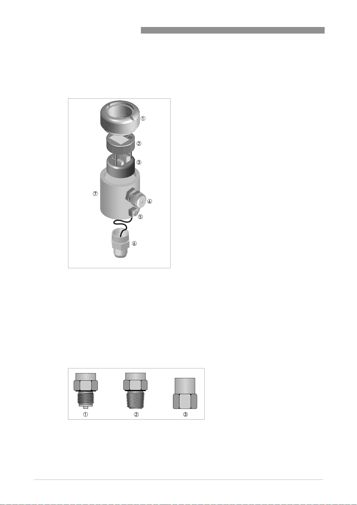
2.2.1 Device design
The following exploded drawing shows the general design of pressure transmitters.
OPTIBAR P 3050 C
Figure 2-2: Device design
1 Stainless steel lid
2 Display unit (optional)
3 Converter module
4 Cable entry
5 Grounding screw
6 Process connection with built-in pressure cell
7 Stainless steel housing
2.2.2 Process connection variants
The following process connection variants are available:
Figure 2-3: Process connection variants
1 G½-B
2 ½" NPT - male
3 ½" NPT - female
12
www.krohne.com 03/2012 - 4001953401 - MA OPTIBAR P3050C R02 en
Page 13

OPTIBAR P 3050 C
2.3 Nameplates
INFORMATION!
Look at the device nameplate to ensure that the device is delivered according to your order.
Check for the correct supply voltage printed on the nameplate.
DEVICE DESCRIPTION 2
Figure 2-4: Example for a nameplate
1 Product name and serial number
2 Type code
3 Specifications for process conditions: measuring range, MWP (= Maximum Working Pressure) and process tempera-
ture limit
4 Electrical data: signal output and power supply
5 Filling oil
6 Protection category
7 Barcode
8 Manufacturer logo and address
www.krohne.com03/2012 - 4001953401 - MA OPTIBAR P3050C R02 en
13
Page 14

3 INSTALLATION
3.1 Notes on installation
INFORMATION!
Inspect the cartons carefully for damages or signs of rough handling. Report damage to the
carrier and to the local office of the manufacturer.
INFORMATION!
Do a check of the packing list to make sure that you have all the elements given in the order.
INFORMATION!
Look at the device nameplate to ensure that the device is delivered according to your order.
Check for the correct supply voltage printed on the nameplate.
3.2 Storage
INFORMATION!
Observe the storage information found on the package. Labels on the original packing must
always remain legible and may not be damaged.
OPTIBAR P 3050 C
• Store the device in a dry, dust-free location.
• Avoid continuous direct sunlight.
• Store the device in its original packing.
• Storage temperature: -20…+70°C / -4…+158°F
3.3 Transport
• Use original packing for transport and ensure that the package does not get crushed or
damaged by sharp objects or other boxes.
• Do not throw or drop the device!
• Avoid temperatures below -20°C/ -4°F and above +70°C / +158°F.
• Observe any transportation information found on the packing.
• When transporting by ship, use seaworthy outer packing.
3.4 Installation specifications
INFORMATION!
Observe the relevant directives, ordinances, standards and accident prevention regulations (e.g.
VDE/VDI 3512, DIN 19210, VBG, Elex V, etc.).
The accuracy of the measurement is only guaranteed if the transmitter and accompanying
impulse line(s), if any, have been correctly installed. In addition, extreme ambient conditions
including large fluctuations in temperature, vibrations and shocks should be kept as far away as
possible from the measuring equipment.
14
www.krohne.com 03/2012 - 4001953401 - MA OPTIBAR P3050C R02 en
Page 15

OPTIBAR P 3050 C
3.5 Installation
CAUTION!
•
Prior to installing the transmitter it is essential to verify whether the version of the device on
hand completely fulfils the technical and safety requirements of the measuring point. This
applies in particular to the measuring range, overpressure resistance, temperature,
explosion protection and operating voltage.
•
Check the materials used for the wetted parts (e.g. gasket, process connection, separating
diaphragm etc.) for suitability as regards product resistance.
3.5.1 Sealing and screwing-in
Connecting shank G:
A flat gasket in accordance with DIN EN 837-1 is required for sealing.
NPT thread connection:
Seal the thread with Teflon or other similar permissible, resistant sealing material.
Process connection for special connections:
Information regarding the installation of variants with special connections is available from the
manufacturer on request.
INSTALLATION 3
3.5.2 Humidity
Use a suitable cable and tighten the cable gland in accordance with the recommended torque
specifications. Protect the transmitter from penetrating moisture by dropping the cable down
before the screw connection. Any liquids running along the cable will thus drip off before
reaching the screw connection; refer to
particularly important for unprotected installation outside or in rooms in which moisture is an
issue (e.g. as a result of cleaning processes) or on cooled or heated containers.
Laying electrical cables correctly
on page 19. This is
www.krohne.com03/2012 - 4001953401 - MA OPTIBAR P3050C R02 en
15
Page 16

3 INSTALLATION
3.5.3 Pressure connection via impulse line
Bear the following in mind when connecting the pressure connection via an impulse line:
• Select the shortest impulse line possible and lay without sharp bends.
• Avoid deposits and blockages in the impulse line. Accordingly, lay the impulse line so that
such occurrences are impossible. Do not exceed a drop or rise of approx. 8% in the pipe.
• Ensure that the impulse line flows freely before the connection and rinse with compressed
air or, even better, with the product itself.
• When measuring liquid, the impulse line must be completely purged of air.
• Run the impulse line so that trapped air (when measuring liquids) or condensate (when
measuring gas) can flow back into the process line.
• Hot steam must not enter the process connection (the excess temperature will destroy the
device). To avoid this situation, a suitable water trap (such as a U-tube filled with water prior
to installation) can be installed upstream from the measuring device.
• Ensure that the connection is perfectly sealed!
3.5.4 Opening the device, installing and dismantling the graphic display
OPTIBAR P 3050 C
DANGER!
Check whether the ambient air around the signal converter is explosive. Opening the signal
converter in an explosive atmosphere may result in ignition and explosion.
DANGER!
The product may cause the signal converter to become extremely hot. Possible risk of burning.
For this reason, promptly shut off the process or isolate the signal converter sufficiently from
the product prior to starting work and check that the converter has cooled down to room
temperature.
DANGER!
For devices used in hazardous areas, additional safety notes apply; please refer to the Ex
documentation.
Electrically, the graphic display is connected to the device using a plug connector on the
connection board with the aid of a flying lead. The display is mechanically fixed by way of a
spacer plugged into the connection board. For optimal readability, the display can be infinitely
rotated on this bracket by 350°, adjusting to any of the pressure transmitter's possible
installation positions.
16
www.krohne.com 03/2012 - 4001953401 - MA OPTIBAR P3050C R02 en
Page 17

OPTIBAR P 3050 C
Procedure
• Ensure that the signal converter has been de-energised!
• Remove the housing cover from the signal converter by hand.
If the housing cover is stuck and cannot be moved by hand, use a suitable square material to
carefully remove it. Place this tool in the flaring located in the housing cover. Take care not to
damage the optionally available window cover! Use a lever action to now carefully apply
greater torque to loosen it. As soon as the housing cover opens, put the tool away and turn the
cover by hand until it opens.
• Ensure that no moisture gets into the device while it is open (drops, spray, liquid mist, etc. …).
• If there is a display, it can be removed by pulling it forward gently. Pay attention to the
connecting cable between the device and the display. To completely remove the display, the
connecting cable must be carefully pulled out of the connector on the board.
i The connection board is now available for further work.
• To install the display and close the housing, follow the steps in reverse order.
Note that the housing covers for devices with displays and devices without displays are
different heights. Never attempt, even on a temporary basis, to install a housing cover for a
blind device on a device with an installed display.
INFORMATION!
Each time a housing cover is opened, the thread should be cleaned and greased. Use only resinfree and acid-free grease.
Ensure that the housing gasket is properly fitted, clean and undamaged.
INSTALLATION 3
3.6 Ventilating the pressure sensor
In the case of gauge pressure transmitters, mechanical reasons make it necessary to charge the
reference side of the pressure sensor with atmospheric pressure. Ventilation occurs in versions
in IP65 via a special aerator fitted with a Gore-Tex
not covered or closed (e.g. covering over with paint not permitted).
For the IP 67 version, a vented cable fitted with a capillary tube must be used. In the process,
ensure that the capillary tubes are vented in a dry room protected from moisture and that no
dust or moisture can penetrate the capillary tube opening.
®
filter. Ensure that the ventilation opening is
www.krohne.com03/2012 - 4001953401 - MA OPTIBAR P3050C R02 en
17
Page 18

4 ELECTRICAL CONNECTIONS
4.1 Safety instructions
DANGER!
All work on the electrical connections may only be carried out with the power disconnected. Take
note of the voltage data on the nameplate!
DANGER!
Observe the national regulations for electrical installations!
DANGER!
For devices used in hazardous areas, additional safety notes apply; please refer to the Ex
documentation.
WARNING!
Observe without fail the local occupational health and safety regulations. Any work done on the
electrical components of the measuring device may only be carried out by properly trained
specialists.
OPTIBAR P 3050 C
INFORMATION!
Look at the device nameplate to ensure that the device is delivered according to your order.
Check for the correct supply voltage printed on the nameplate.
4.2 Notes for electrical cables
DANGER!
The device must be grounded to a spot in accordance with regulations in order to protect
personnel against electric shocks.
DANGER!
Cables may only be connected when the power is switched off! Since the transmitter has no
switch-off elements, overcurrent protection devices, lightning protection and/or energy isolating
devices must be provided by the customer.
18
www.krohne.com 03/2012 - 4001953401 - MA OPTIBAR P3050C R02 en
Page 19

OPTIBAR P 3050 C
ELECTRICAL CONNECTIONS 4
4.2.1 Requirements for signal cables provided by the customer
INFORMATION!
If the signal cable was not ordered, it is to be provided by the customer. The following
requirements regarding the electrical values of the signal cable must be observed:
Specifications for standard signal cables
• 2 twisted double wire circuits
• 20 AWG twisted, tinned copper conductors
• Completely tinned copper shielding
• Casing colour: grey
• Colour of wires:
Pair 1: black / red; pair 2: green / white
• Test voltage: ≥ 500 VAC RMS (750 VDC)
• Temperature range: -40...+105°C / -40...+221°F
• Capacity: ≤ 200 pF/m / 61 pF/ft
• Inductance: ≤ 0.7 µH/m / 0.2 µH/ft
4.2.2 Laying electrical cables correctly
Figure 4-1: Protect housing from dust and water
1 Lay the cable in a loop just before the housing.
2 Tighten the screw connection of the cable entry securely.
3 Never mount the housing with the cable entries facing upwards.
4 Seal cable entries that are not needed with a plug.
www.krohne.com03/2012 - 4001953401 - MA OPTIBAR P3050C R02 en
19
Page 20

4 ELECTRICAL CONNECTIONS
4.2.3 Connection to the feed unit
Figure 4-2: Connection to the feed unit
1 Red
2 Black
3 Green/yellow
4 Feed unit with load
4.3 Electrical connection
4.3.1 Tailoring the cables
OPTIBAR P 3050 C
Depending on the version supplied, the electrical connection requires an M16x1.5 cable
connection (for cable diameters: 5...10 mm / 0.2...0.4") or M20x1.5 and ½"NPT (the latter via an
adapter). The terminals in the terminal compartment are designed for wire widths of up to
1.5 mm². To ensure a proper connection, you should strip the cable 40…50 mm / 1.6...2".
Figure 4-3: Stripping the cable
1 40...50 mm / 1.6...2"
2 5mm/ 0.2"
20
www.krohne.com 03/2012 - 4001953401 - MA OPTIBAR P3050C R02 en
Page 21

OPTIBAR P 3050 C
4.3.2 Connection in the terminal compartment
Figure 4-4: Connection in the terminal compartment
1 (V
) signal terminals
in+
2 (V
) signal terminals
in-
3 (PE) grounding terminal or equipotential bonding terminal
4 Push button for measurement span start and span end
ELECTRICAL CONNECTIONS 4
CAUTION!
When using an intrinsically safe or grounded feed unit, do not connect PE!
www.krohne.com03/2012 - 4001953401 - MA OPTIBAR P3050C R02 en
21
Page 22

4 ELECTRICAL CONNECTIONS
4.4 Grounding the measuring device
DANGER!
There should be no difference in potential between the pressure sensor and the housing or
protective earth of the transmitter!
• The pressure sensor must be properly grounded.
• When using an intrinsically safe or grounded feed unit, do not connect PE!
• Do not use the grounding cable to connect any other electrical devices to ground at the same
time.
• The pressure transmitter is connected to ground by means of a functional grounding
conductor.
• In hazardous areas, grounding is used at the same time for equipotential bonding.
A ground terminal is provided on the outside of the housing to accommodate wire widths of up to
2
1.5 mm
.
OPTIBAR P 3050 C
Figure 4-5: Position of the ground terminal on the housing
1 Ground terminal
4.5 Description of the current output
The current output is a 2-wire 4...20 mA output.
Overload condition:
• Lower limit: 3.8 mA
• Upper limit: 20.5 mA
Alarm current:
• Low alarm current: 3.6 mA
• High alarm current: 21 mA
Standard setting: High alarm current
The transmitter works with voltages of 12...45 VDC, no load.
[KΩ] = (UB [V] - 12 V) / alarm current max. [mA]
R
Load
where U
= supply voltage and R
B
= max. load resistance (load)
Load
22
www.krohne.com 03/2012 - 4001953401 - MA OPTIBAR P3050C R02 en
Page 23

OPTIBAR P 3050 C
5.1 Start-up
The pressure transmitter may only be started up after it has been completely installed and
checked by appropriately qualified personnel. Switch on the operating voltage for start-up. Prior
to applying the operating voltage, it is crucial to check the correctness of the process connection
and the electrical connection and ensure that the impulse line has been completely filled with
the process medium. Then proceed with start-up. If available, the shut-off fixtures are to be
activated in the following sequence (all valves are closed in the base setting):
• Open extraction shut-off valve, if any.
• Open shut-off valve, if any.
For shut-down reverse the order.
INFORMATION!
Please note that absolute pressure transmitters with measuring ranges ≤100 kPa abs. (1 bara)
were affected by the externally present atmospheric pressure during transport and storage. A
warm-up period of several hours following start-up is therefore required in order to reach the
specified accuracy.
OPERATION 5
5.2 Factory settings and settings during reset
The pressure transmitter factory settings can be based on a measuring span specified by the
customer in the order. This and other information is located on the device nameplate. If the
customer has not specified any settings, the device always leaves the factory with the following
settings:
Device parameter Factory pre-setting
Lower range limit (zero point) 4mA
Upper range limit (URL) 20 mA
Alarm current High alarm 21 mA
Damping 0.1 s
Main display value [*] Pressure value in % URL
Sensor temperature [*] Indication in K
Write protection [*] No
Language [*] English
Contrast [*] 50%
Bargraph indication [*] Yes
[*] only with optional LCD display
During a reset (which can be selected using the keyboard on the display), the pressure
transmitter is automatically started with the above factory settings.
For a factory reset without LCD display, push the push button on the converter electronics for
more than 30 seconds.
www.krohne.com03/2012 - 4001953401 - MA OPTIBAR P3050C R02 en
23
Page 24

5 OPERATION
5.3 General setting options
Both the setting options and the procedure for setting the measuring device parameters differ
greatly between the blind version and the version with display. With the display version,
advanced setting and configuration options are available without requiring the push button on
the converter electronics. For this reason, the settings for the respective versions are each
described separately below.
5.4 Setting the blind device
To adjust the settings on the blind device you require access to the push button located on the
converter electronics.
5.4.1 Position correction
The measuring device is set to be installed vertically (cover opens up) when it leaves the factory.
Zero point shifts may occur when installing the pressure transmitter (e.g. slightly angular
installation site or through pressure sensors etc.). These shifts must be rectified.
INFORMATION!
Prior to starting with the correction, ensure that the pressure transmitter has already reached
its operating temperature (approx. 5 minutes operating time, where the pressure transmitter
has already reached the ambient temperature).
OPTIBAR P 3050 C
5.4.2 Zero point and span start (4 mA)
Open the housing cover (for details refer to
graphic display
or from a pressure transducer. The pressure must be stable and extremely accurate (<< 0.15%).
Hold the push button (1) down with a blunt object and release within 0.5...2 seconds. The span
start set in this way is stored power failure proof.
Figure 5-1: Zero point setting and position correction for devices without display
1 Push button
on page 16). The pressure span start (4 mA) is provided either from the process
Opening the device, installing and dismantling the
24
www.krohne.com 03/2012 - 4001953401 - MA OPTIBAR P3050C R02 en
Page 25

OPTIBAR P 3050 C
5.4.3 Span end (20 mA)
OPERATION 5
Open the housing cover (for details refer to
graphic display
or from a pressure transducer. The pressure must be stable and extremely accurate (<< 0.15%).
Hold the push button (1) down for at least 5 seconds using a blunt object and then release within
10 seconds. The span end set in this way is stored power failure proof.
on page 16). The pressure span end (20 mA) is provided either from the process
5.4.4 Factory reset
Open the housing cover (for details refer to
graphic display
object and then release it. The pressure transmitter now resets itself and loads the factory
settings (see details on page 23).
on page 16). Hold down the push button (1) for at least 30 seconds using a blunt
5.5 Setting the version with display
5.5.1 Display and operating elements
The following illustrations show examples of the display while in measuring mode, in the
selection menu and when configuring measurement values.
Display during measuring mode
Opening the device, installing and dismantling the
Opening the device, installing and dismantling the
Figure 5-2: Example of display during normal measuring mode
1 TAG ID
2 Measured value
3 Bargraph indication in %
4 Unit of measured value
www.krohne.com03/2012 - 4001953401 - MA OPTIBAR P3050C R02 en
25
Page 26

5 OPERATION
Display in selection menu
Figure 5-3: Example of display in the selection menu for device configuration
1 Selected main menu
2 List of possible submenus
3 Button for menu selection (SEL)
4 Button used to go back one level in the menu (BACK)
5 Button in the menu used to navigate down the list (↓)
6 Button in the menu used to navigate up the list (↑)
Display for configuration of settings
OPTIBAR P 3050 C
Figure 5-4: Example of display when editing the setting values
1 Menu name of setting value
2 Setting value to be edited and corresponding unit
3 Button to select editing mode (EDIT)
4 Button used to go back one level in the menu (BACK)
Navigation in the operating menu
MENU SEL EDIT
→ → →
Normal
operation
← ← ↑↓ ←
BACK BACK SAVE
Config.
menu
Editing
menu
QUIT
Edit
BACK
26
www.krohne.com 03/2012 - 4001953401 - MA OPTIBAR P3050C R02 en
Page 27

OPTIBAR P 3050 C
5.5.2 Structure of the operating menu
Measuring mode/menu Function of the existing buttons
Display mode and normal mode MENU: indicate menu
Selection mode and configuration
menu
Editing menu Edit numerical value:
BACK: back to indication
• ↓: contrast darker
• ↑: contrast lighter
SEL: select menus
BACK: one level back
↓: navigate down the list
↑: navigate up the list
Edit numerical value:
Edit numerical value:Edit numerical value:
SEL: select digit position
BACK: store
↓: reduce value or browse character map
↑: increase value or browse character map
Confirm set numerical value:
Confirm set numerical value:
Confirm set numerical value:Confirm set numerical value:
EDIT: back to editing mode
BACK: one level back
QUIT: reset to original value
SAVE: save new value
Selection from list or confirm action:
Selection from list or confirm action:
Selection from list or confirm action:Selection from list or confirm action:
SAVE: save selection
BACK: one level back
↓: navigate down the list
↑: navigate up the list
OPERATION 5
www.krohne.com03/2012 - 4001953401 - MA OPTIBAR P3050C R02 en
27
Page 28

5 OPERATION
OPTIBAR P 3050 C
5.5.3 Description of the function
Main menu Description
Submenu
Config Device
Write Protection Switches on/off write protection for the transmitter.
Factory reset is possible despite write protection. Preset PIN: 3050
Proc. Pres. Read Reads the active process pressure as measurement span start or measurement span end.
Meas. Span. Start Determines the active pressure as the new measurement span start.
Meas. Span. End Determines the active pressure as the new measurement span end.
Measurement Span Provides setting options for the measurement span in terms of the unit and manually
Meas. Span Unit Determines the measurement span unit.
Meas. Span. Start Manually determines the measurement span start.
Meas. Span. End Manually determines the measurement span end.
PV Offset Determines the active pressure as the new zero point and shifts the upper/lower limit value by
Loop Current Provides setting options as regards the upper/lower current limit and the alarm current.
Upper Limit Manually determines the upper limit of the output current.
Lower Limit Manually determines the lower limit of the output current.
High Alarm Value Determines the high alarm value which is output as current.
Low Alarm Value Determines the low alarm value which is output as current.
Alarm Current Selection option as to whether the high alarm value or low alarm value should be output as
Proc. Var. Unit Provides the selection option for the process value unit on the local LCD display.
Sens. Temp. Unit Provides the selection option for the unit of temperature on the local LCD display.
Factory Reset Resets all settings to those configured at the factory (see details on page 23).
determines the measurement span start or end.
Available units:
mbar; bar; pa; kpa; Mpa; Torr; psi; atm; gf/cm²; kgf/cm²; mm HG (0°C); in HG (0°C);
mm H2O (4°C); mm H2O (68°F); in H2O (4°C); in H2O (60°F); in H2O (68°F); ft H2O (68°F)
the new offset.
Function only available with gauge pressure.
alarm current.
Available units:
mbar; bar; pa; kpa; Mpa; Torr; psi; atm; gf/cm²; kgf/cm²; mm HG (0°C); in HG (0°C);
mm H2O (4°C); mm H2O (68°F); in H2O (4°C); in H2O (60°F); in H2O (68°F); ft H2O (68°F)
Available units:
K; °C; °F
Display
Display Value Selection option of the displayed measured value.
Bargraph Activates or deactivates the bar graph in the start view. The bar graph indicates the output in
Contrast Setting option to increase or decrease the display contrast (between 30...100%).
Language Selection of display language.
Version ODU Indicates the active software version of the display module.
Version CCT Indicates the active software version of the device.
Serial number Indicates the device serial number.
28
percent (0%...100%) of the measuring span.
Softkeys remain unaffected.
www.krohne.com 03/2012 - 4001953401 - MA OPTIBAR P3050C R02 en
Page 29

OPTIBAR P 3050 C
Main menu Description
Submenu
Diagnosis
Process Value Indicates the active process value.
Sensor Temperature Indicates the active sensor temperature
Output Current Indicates the active output current.
Output in Percent Indicates the output in percent of the measuring span.
Identification
Tag Name Specifies the name of the device (maximum 16 characters).
OPERATION 5
www.krohne.com03/2012 - 4001953401 - MA OPTIBAR P3050C R02 en
29
Page 30

6 SERVICE
OPTIBAR P 3050 C
6.1 Replacing the pressure sensor, the electronics and the display
DANGER!
All work on the electrical connections may only be carried out with the power disconnected. Take
note of the voltage data on the nameplate!
DANGER!
Check whether the ambient air around the pressure transmitter is explosive. Opening the signal
converter in an explosive atmosphere may result in ignition and explosion.
DANGER!
The product may cause the pressure transmitter to become extremely hot. Possible risk of
burning. For this reason, promptly shut off the process or isolate the pressure transmitter
sufficiently from the product prior to starting work and check that it has cooled down to room
temperature.
WARNING!
Observe without fail the local occupational health and safety regulations. Any work done on the
electrical components of the measuring device may only be carried out by properly trained
specialists.
DANGER!
Observe the waiting period for Ex devices.
Pressure sensor and electronics
Pressure sensor and electronics
Pressure sensor and electronicsPressure sensor and electronics
When used as intended in normal operation, the pressure transmitter is completely
maintenance-free. For this type of device, the manufacturer makes no provision for repairs,
replacement of electronics or measuring element for the user. To ensure safe operation, the
entire device must be replaced in the event of damage to or failure of the pressure sensor or the
electronics. The replaced device may not be repaired for reasons of safety. Please clearly mark
the device as defective and dispose of it properly.
CAUTION!
Adhere to national disposal regulations. Proper disposal avoids negative consequences for
people and the environment and allows valuable raw materials to be recycled.
30
www.krohne.com 03/2012 - 4001953401 - MA OPTIBAR P3050C R02 en
Page 31

OPTIBAR P 3050 C
Display
It is also not permitted to repair faulty displays. They must simply be replaced by a new display
module. However, in this case, the reason for the damage or failure of the graphic display must
be reported. If the failure is the result of overheating or overloading the device, the entire device
must be marked clearly as defective, must be replaced and then disposed of properly. Repair is
not permitted!
INFORMATION!
For detailed information please contact your local representative.
6.2 Spare parts availability
The manufacturer adheres to the basic principle that functionally adequate spare parts for each
device or each important accessory part will be kept available for a period of 3 years after
delivery of the last production run for the device.
This regulation only applies to spare parts which are subject to wear and tear under normal
operating conditions.
SERVICE 6
6.3 Availability of services
The manufacturer offers a range of services to support the customer after expiration of the
warranty. These include repair, maintenance, technical support and training.
INFORMATION!
For more precise information, please contact your local representative.
6.4 Repairs
Repairs may be carried out exclusively by the manufacturer or the manufacturer authorised
specialist companies.
www.krohne.com03/2012 - 4001953401 - MA OPTIBAR P3050C R02 en
31
Page 32

6 SERVICE
6.5 Returning the device to the manufacturer
6.5.1 General information
This device has been carefully manufactured and tested. If installed and operated in accordance
with these operating instructions, it will rarely present any problems.
CAUTION!
Should you nevertheless need to return a device for inspection or repair, please pay strict
attention to the following points:
•
Due to statutory regulations on environmental protection and safeguarding the health and
safety of our personnel, manufacturer may only handle, test and repair returned devices that
have been in contact with products without risk to personnel and environment.
•
This means that the manufacturer can only service this device if it is accompanied by the
following certificate (see next section) confirming that the device is safe to handle.
CAUTION!
If the device has been operated with toxic, caustic, flammable or water-endangering products,
you are kindly requested:
•
to check and ensure, if necessary by rinsing or neutralizing, that all cavities are free from
such dangerous substances,
•
to enclose a certificate with the device confirming that is safe to handle and stating the
product used.
OPTIBAR P 3050 C
32
www.krohne.com 03/2012 - 4001953401 - MA OPTIBAR P3050C R02 en
Page 33

OPTIBAR P 3050 C
6.5.2 Form (for copying) to accompany a returned device
Company: Address:
Department: Name:
Tel. no.: Fax no.:
Manufacturer's order no. or serial no.:
The device has been operated with the following medium:
SERVICE 6
This medium is: water-hazardous
toxic
caustic
flammable
We checked that all cavities in the device are free from such
substances.
We have flushed out and neutralized all cavities in the
device.
We hereby confirm that there is no risk to persons or the environment through any residual media
contained in the device when it is returned.
Date: Signature:
Stamp:
6.6 Disposal
CAUTION!
Disposal must be carried out in accordance with legislation applicable in your country.
www.krohne.com03/2012 - 4001953401 - MA OPTIBAR P3050C R02 en
33
Page 34

7 TECHNICAL DATA
7.1 Measuring principle
Figure 7-1: Measuring principle for pressure measurement
1 Signal cables of measuring bridge
2 Ventilation (only with gauge pressure transmitters)
3 Silicone cell
4 Silicone diaphragm with piezoresistive elements
5 Liquid fill
6 Process pressure "P"
7 Metal diaphragm
OPTIBAR P 3050 C
The process pressure is transmitted from the metal diaphragm (7) via the liquid fill behind it
(5) directly to the silicone measuring cell (3). The embedded piezoresistive measuring
elements on the silicone diaphragm (4) experience a corresponding strain which is then
converted via a Wheatstone Bridge circuit to a voltage proportional to the applied process
pressure.
Absolute pressure, gauge pressure and vacuum can be measured using this measuring
principle.
34
www.krohne.com 03/2012 - 4001953401 - MA OPTIBAR P3050C R02 en
Page 35

OPTIBAR P 3050 C
Available measurement configurations
a: Pe = Effective pressure [2 bar]
b: P
amb
c: P
= Vacuum [0 bar]
0
1 Absolute pressure [1.513 bara]
2 Gauge pressure [0.5 barg]
Absolute pressure
During the production process, the sensor is evacuated on the negative side of the measuring
cell and then sealed and referenced against a vacuum.
The pressure transmitter now measures the absolute pressure (1) compared to a "zero"
pressure in an empty space (vacuum).
TECHNICAL DATA 7
= Ambient pressure [1.013 bar]
Gauge pressure
The back of the sensor is open to the atmosphere via air ventilation. The device is thus
automatically referenced to the continuously changing ambient air pressure, indicating the
gauge pressure (2) in the process compared to the respective atmospheric pressure.
www.krohne.com03/2012 - 4001953401 - MA OPTIBAR P3050C R02 en
35
Page 36

7 TECHNICAL DATA
OPTIBAR P 3050 C
7.2 Technical data
INFORMATION!
•
The following data is provided for general applications. If you require data that is more
relevant to your specific application, please contact us or your local representative.
•
Additional information (certificates, special tools, software,...) and complete product
documentation can be downloaded free of charge from the website (Download Center).
Measuring system
Measuring principle Metallic diaphragm with piezoresistive measuring cell
Application range Measurement of absolute and gauge pressure of gases, vapours and liquids
Measuring ranges
Measuring ranges
Measuring rangesMeasuring ranges
Absolute pressure Pressure ranges [bara]: 0…0.5; 0…1; 0…5; 0…10; 0…40; 0…100; 0…200
Pressure ranges [psia]: 0…7.25; 0…14.5; 0…72.5; 0…145; 0…580; 0…2900
Gauge pressure Pressure ranges [barg]: 0…0.2; 0…0.5; 0…1; 0…2; 0…5; 0…10; 0…20
Pressure ranges [psig]: 0…2.9; 0…7.25; 0…14.5; 0…29; 0…72.5; 0…145;
0…290
Design
Blind version Position correction, zero and measurement span adjustment of span start
Version with display (optional) LCD graphic display with 4 push buttons.
(4 mA) and span end (20 mA) with push button on the converter electronics.
Resolution: 128 x 64
User languages: German, English and French (in preparation)
Measuring accuracy
Reference conditions acc. to
IEC 60770
Measuring accuracy In relation to non-linearity, hysteresis and repeatability
Long-term stability acc. to
DIN EN 61298-1
Response time acc. to IEC 61298-1 T(95%) = 50 ms (incl. dead time)
Ambient temperature (constant): +18...+30°C / +64...+86°F
Relative humidity (constant): 30...80%
Ambient pressure (constant): 950...1060 mbar / 14.8...15.4 psi
Filling: silicone oil
±0.1% of measuring span
≤±0.1% within 1 year
36
www.krohne.com 03/2012 - 4001953401 - MA OPTIBAR P3050C R02 en
Page 37

OPTIBAR P 3050 C
TECHNICAL DATA 7
Operating conditions
Temperature limits
Temperature limits
Temperature limitsTemperature limits
Operating temperature Blind version: -40…+85°C / -40...+185°F
With LCD graphic display: -20…+70°C / -4…+158°F
Ambient temperatures below -10°C / +14°F may affect the readability of the
display.
Process temperature -40…+85°C / -40...+185°F
Storage temperature -20…+70°C / -4…+158°F
Other conditions
Other conditions
Other conditionsOther conditions
Protection category acc. to IEC 529 /
EN 60529
Standard: IP65
Optional: IP67 with internally ventilated cable for gauge pressure sensors
Installation conditions
Installation Can be installed in any position, zero point or position correction may be
Dimensions and weights For detailed information refer to section "Dimensions and weights".
required following installation.
Maximum error through mounting position: <3.5 mbar / <0.05 psi
Materials
Wetted parts Stainless steel W.1.4404 (AISI 316L)
Non-wetted parts Stainless steel W.1.4404 (AISI 316L)
Internal housing cover gasket: EPDM
Version with display: Makrolon
®
Process connections
Standard G½-B acc. to DINEN837-1
NPT versions ½"-14 NPT - female
½"-14 NPT - male
Process connections with flush
mounted diaphragm
In preparation
Electrical connection
Supply voltage 12...45 VDC
Output signal 4...20 mA, 2-wire
Damping 0.1 s
Max. load resistance (current output) R
Initialisation time 10 s
Alarm current Configurable as high alarm (21 mA) and low alarm (3.6 mA) using optional LCD
Cable feedthroughs M16 in plastic, nickel-plated brass or 316L stainless steel
[KΩ] = (UB [V] - 12 V) / alarm current max. [mA]
Load
= supply voltage
with U
B
display
www.krohne.com03/2012 - 4001953401 - MA OPTIBAR P3050C R02 en
37
Page 38

7 TECHNICAL DATA
OPTIBAR P 3050 C
Approvals and certificates
CE The device fulfils the statutory requirements of the EC directives. The
Electromagnetic compatibility (EMC) Electromagnetic influence < 0.5% of measuring span
NAMUR NE 43
manufacturer certifies that these requirements have been met by applying the
CE marking.
EMC conformity for EN 61326-1 (05/2006)
7.3 Pressure ranges
Gauge pressure
Order code Pressure range Maximum working
pressure
Smallest
calibratable span
Low pressure
resistance p
[bar] / [psi] [bar] [bar] [bar]
1 -0.2...0.2 / -3...3 2.5 0.02 0.05
2 -0.5...0.5 / -7...7 2.5 0.05 0.05
3 -1...1 / -15...15 3 0.1 0.05
4 -1...2 / -15...145 4 0.2 0.05
5 -1...5 / -15...72 7 0.5 0.05
6 -1...10 / -15...145 15 1 0.05
7 -1...20 / -15...290 30 2 0.05
Absolute pressure
Order code Pressure range Maximum working
pressure
[bar] / [psi] [bar] [bar] [bar]
N 0...0.5 / 0...7 2.5 0.05 0.05
P 0...1 / 0...15 3 0.01 0.05
R 0...5 / 0...72 7 0.5 0.05
S 0...10 / 0...145 15 1 0.05
T 0...50 / 0...725 100 5 0.05
U 0...100 / 0...1450 200 10 0.05
V 0...200 / 0...2900 300 20 0.05
Smallest
calibratable span
Low pressure
resistance p
abs.
abs.
38
www.krohne.com 03/2012 - 4001953401 - MA OPTIBAR P3050C R02 en
Page 39

OPTIBAR P 3050 C
7.4 Dimensions and weights
TECHNICAL DATA 7
Figure 7-2: Dimensions for available process connection variants
d = WS27
e = M16x1.5
1 G½
2 ½" NPT - male
3 ½" NPT - female
Version Dimensions Weight
a b c
[mm / "] [g / lb]
Process connection G½
Blind version 60 / 2.4 71 / 2.8 124 / 4.9 734 / 1.60
Version with display 60 / 2.4 79 / 3.1 132 / 5.2 834 / 1.80
Process connection ½" NPT - male
Blind version 60 / 2.4 71 / 2.8 121 / 4.8 710 / 1.57
Version with display 60 / 2.4 79 / 3.1 129 / 5.1 810 / 1.78
Process connection ½" NPT - female
Blind version 60 / 2.4 71 / 2.8 118 / 4.6 748 / 1.65
Version with display 60 / 2.4 79 / 3.1 126 / 5.0 834 / 1.80
www.krohne.com03/2012 - 4001953401 - MA OPTIBAR P3050C R02 en
39
Page 40

KROHNE product overview
• Electromagnetic flowmeters
• Variable area flowmeters
• Ultrasonic flowmeters
• Mass flowmeters
• Vortex flowmeters
• Flow controllers
• Level meters
• Temperature meters
• Pressure meters
• Analysis products
• Products and systems for the oil & gas industry
• Measuring systems for the marine industry
Head Office KROHNE Messtechnik GmbH
Ludwig-Krohne-Str. 5
47058 Duisburg (Germany)
Tel.:+49 (0)203 301 0
Fax:+49 (0)203 301 10389
info@krohne.de
© KROHNE 03/2012 - 4001953401 - MA OPTIBAR P3050C R02 en - Subject to change without notice.
The current list of all KROHNE contacts and addresses can be found at:
www.krohne.com
 Loading...