

Page 1
Supplementary instructions
Supplementary instructions
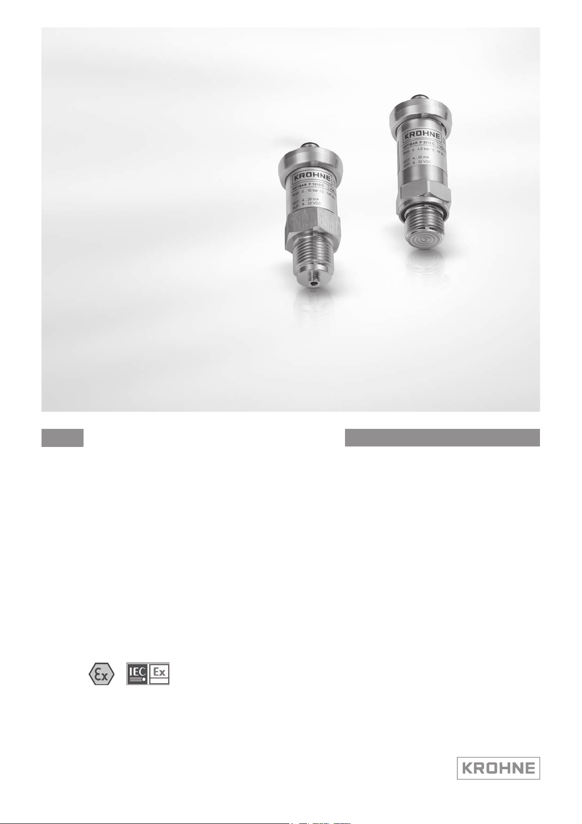
OPTIBAR P 1010/2010 C
OPTIBAR P 1010/2010 C
OPTIBAR P 1010/2010 COPTIBAR P 1010/2010 C
Supplementary instructions Supplementary instructions
Pressure transmitter
Equipment category II 1G / Ga, II 1D / Da in protection type intrinsic safety Exi
© KROHNE 01/2014 - 4002866801 - AD OPTIBAR PX010 Ex R01en
Page 2

CONTENTS
OPTIBAR P 1010/2010 C
1 Safety instructions 3
1.1 General notes ................................................................................................................... 3
1.2 EC conformity ................................................................................................................... 3
1.3 Approval according to the IECEx scheme ........................................................................ 3
1.4 Safety instructions............................................................................................................ 4
2 Device description 5
2.1 Device description ............................................................................................................ 5
2.2 Marking............................................................................................................................. 5
2.3 Flammable products ........................................................................................................ 6
2.4 Equipment category .........................................................................................................6
2.5 Protection types................................................................................................................ 6
2.6 Ambient temperature / temperature classes.................................................................. 7
2.7 Electrical data................................................................................................................... 7
3 Installation 8
3.1 Installation........................................................................................................................ 8
4 Electrical connections 9
4.1 General notes ................................................................................................................... 9
4.2 Power supply .................................................................................................................... 9
4.3 Inputs/outputs .................................................................................................................. 9
4.4 Grounding and equipotential bonding.............................................................................. 9
5 Operation 10
5.1 Start-up........................................................................................................................... 10
5.2 Operation ........................................................................................................................ 10
5.3 Electrostatic charge .......................................................................................................10
6 Service 11
6.1 Maintenance ................................................................................................................... 11
6.2 Dismantling .................................................................................................................... 11
2
www.krohne.com 01/2014 - 4002866801 - AD OPTIBAR PX010 Ex R01en
Page 3

OPTIBAR P 1010/2010 C
1.1 General notes
These additional instructions apply to explosion-protected versions of the pressure transmitter
OPTIBAR P 1010 C / P 2010 C with the marking II 1 G or II 1 D. They complete the standard
documentation for non-explosion protected versions.
The information given in these instructions contains only the data relevant to Category 1
explosion protection. The technical details given in the standard documentation for the nonexplosion protected versions apply unchanged unless excluded or superseded by these
instructions.
1.2 EC conformity
The manufacturer declares with the EC declaration of conformity on his own responsibility
conformity with the protection goals of directive 94/9/EG acc. to EN 60079-0 and EN 60079-11 for
use in hazardous areas with gas.
The EC type test certificate of the Institut für Sicherheitstechnik GmbH forms the basis of the EC
declaration of conformity:
SAFETY INSTRUCTIONS 1
IBExU 13 ATEX 1133 X
IBExU 13 ATEX 1133 X
IBExU 13 ATEX 1133 XIBExU 13 ATEX 1133 X
The "X" after the certificate number refers to special conditions for safe use of the device, which
have been listed in these instructions.
The EC type test certificate may be downloaded from the manufacturer's website as needed.
1.3 Approval according to the IECEx scheme
Conformity with IECEx standards was tested in accordance with the IECEx Certification Scheme
for Explosive Atmospheres acc. to IEC 60079-0, IEC 60079-11 and IEC 60079-26. The number of
the IEC certificate is:
IECEx IBE 13.0050 X
IECEx IBE 13.0050 X
IECEx IBE 13.0050 XIECEx IBE 13.0050 X
The "X" after the certificate number refers to special conditions for safe use of the device, which
have been listed in these instructions.
The EC type test certificate may be downloaded from the manufacturer's website as needed.
www.krohne.com01/2014 - 4002866801 - AD OPTIBAR PX010 Ex R01en
3
Page 4

1 SAFETY INSTRUCTIONS
1.4 Safety instructions
Assembly, installation, start-up and maintenance may only be performed by personnel trained in
explosion protection!
CAUTION!
The operator or his agent is responsible for observing any additional standards, directives or
laws if required due to operating conditions or place of installation. This applies in particular to
the use of easily detachable process connections when measuring flammable media.
OPTIBAR P 1010/2010 C
4
www.krohne.com 01/2014 - 4002866801 - AD OPTIBAR PX010 Ex R01en
Page 5

OPTIBAR P 1010/2010 C
2.1 Device description
The OPTIBAR P 1010 C / P 2010 C pressure transmitters are designed to measure the absolute
pressure and gauge pressure in flammable and non-flammable gases and liquids. The pressure
transmitters are supplied as standard with 2-wire, 4...20 mA signal outputs.
2.2 Marking
The marking of the entire device is on the housing, where the following identification plate can be
found.
DEVICE DESCRIPTION 2
Figure 2-1: Example of an identification plate
1 Device type
2 Manufacturer
3 Note to observe the documentation
4 Manufacturer's website
5 Identification number for CE marking
6 Approval-related connection data
7 Ex approval-related information
8 Electrical connection data
9 Rating data: measuring range, MWP
www.krohne.com01/2014 - 4002866801 - AD OPTIBAR PX010 Ex R01en
5
Page 6

2 DEVICE DESCRIPTION
2.3 Flammable products
Atmospheric conditions:
Atmospheric conditions:
Atmospheric conditions:Atmospheric conditions:
An explosive atmosphere is a mixture of air and flammable gases, vapours, mists or dusts under
atmospheric conditions. It is defined by the following values
= -20...+60°C / -4...+140°F and P
T
atm
Outside of this range, no key figures are available as to ignition behaviour for most mixtures.
Operating conditions:
Operating conditions:
Operating conditions:Operating conditions:
Outside of atmospheric conditions you cannot apply explosion protection according to directive
94/9/EC (ATEX) – regardless of the zone assignment - due to the lack of key safety data.
2.4 Equipment category
Pressure transmitters are rated in the Categories II 1G or EPL Ga for use in zone 0 and II 1D or
Da for use in zone 20.
2.5 Protection types
= 0.8...1.1 bar / 11.6...15.9 psi.
atm
OPTIBAR P 1010/2010 C
The pressure transmitter is designed with protection type intrinsic safety, protection level "ia"
according to EN 60079-11.
The marking is:
acc. to ATEX:
II 1G Ex ia IIC T4 Ga or II 1D Ex ia T85
II 1G Ex ia IIC T4 Ga or II 1D Ex ia T85°C
II 1G Ex ia IIC T4 Ga or II 1D Ex ia T85II 1G Ex ia IIC T4 Ga or II 1D Ex ia T85
C
CC
acc. to IECEx:
Ex ia IIC T4 Ga or Ex ia IIIC T85
Ex ia IIC T4 Ga or Ex ia IIIC T85°C Da
Ex ia IIC T4 Ga or Ex ia IIIC T85Ex ia IIC T4 Ga or Ex ia IIIC T85
The marking contains the following information:
The marking contains the following information:
The marking contains the following information:The marking contains the following information:
II
II Group II explosion protection
IIII
1111 Equipment category 1
GGGG Gas explosion protection
Ex ia
Ex ia Intrinsically safe, level of protection "ia"
Ex iaEx ia
IIC
IIC Gas group, suitable for gas groups IIC, IIB and IIA
IICIIC
IIIC
IIIC Dust group, suitable for dust groups IIIA, IIIB and IIIC
IIICIIIC
T4
T4 Temperature class, suitable for temperature classes T4...T1
T4T4
Ga
Ga EPL, suitable for zone 0
GaGa
Da
Da EPL, suitable for zone 20
DaDa
C Da
C DaC Da
The marking contains the following information:
The marking contains the following information:
The marking contains the following information:The marking contains the following information:
II
II Group II explosion protection
IIII
1111 Equipment category 1
DDDD Dust explosion protection
T85
T85°CCCC Maximum surface temperature 85°C / 185°F
T85T85
6
www.krohne.com 01/2014 - 4002866801 - AD OPTIBAR PX010 Ex R01en
Page 7

OPTIBAR P 1010/2010 C
2.6 Ambient temperature / temperature classes
DEVICE DESCRIPTION 2
Use in zone 0 / zone 20
(P
Use from zone 1 / zone 21
zone 0 / zone 20, ambient temperature range: -20...+60°C / -4...+140°F
zone 0 / zone 20zone 0 / zone 20
: 0.8...1.1 bar / 11.6...15.9 psi)
atm
zone 1 / zone 21, ambient temperature range: -20...+70°C / -4...+158°F
zone 1 / zone 21zone 1 / zone 21
2.7 Electrical data
Signal output: 4...20 mA, 2-wire
Nominal voltage: 10...28 VDC
Nominal current: 4...20 mA
Built-in equipment for the pressure transmitters may only be connected to separate intrinsically
safe circuits with the following maximum values:
[V]: 28 V
• U
i
[mA]: 93 mA
• I
i
[mW]: 660 mW
• P
i
[nF]: ~ 0 nF
• C
i
[µH]: ~ 0 µH
• L
i
The supply connections have a maximum internal capacity of 27 nF to the housing plus circuit
inductivities 1 µH/m and circuit capacities 160 pF/m (for factory cable).
www.krohne.com01/2014 - 4002866801 - AD OPTIBAR PX010 Ex R01en
7
Page 8

3 INSTALLATION
3.1 Installation
Installation and setup must be carried out according to the applicable installation standards (e.g.
EN 60079-14) by qualified personnel trained in explosion protection. The information given in the
manuals and the supplementary instructions must be observed at all times.
Install pressure transmitters so that
• there is sufficient overvoltage protection in the event of lightning or overvoltage.
• they are not in a pneumatic flow.
• excessive dust deposits (over 5 mm) and complete dust coverage are prevented.
• there is no danger from mechanical impact effects.
• the device is accessible for any necessary visual inspections and can be viewed from all sides.
• the nameplate is clearly visible.
• it can be operated from a location with secure footing.
CAUTION!
The manufacturer is not liable for any damage resulting from improper use or use other than the
intended purpose. This applies in particular to hazards due to insufficient corrosion resistance
and suitability of the materials in contact with product.
OPTIBAR P 1010/2010 C
8
www.krohne.com 01/2014 - 4002866801 - AD OPTIBAR PX010 Ex R01en
Page 9

OPTIBAR P 1010/2010 C
4.1 General notes
Overvoltage protection
If the pressure transducer is being used as category 1 G equipment, a suitable overvoltage
protection device must be installed upstream (see Industrial Safety Regulations [BetrSichV]
formerly Technical Regulations for Flammable Liquids [TRbF100] and EN 60079-14).
Circuits
The circuits are designed in protection type "intrinsically safe".
The connecting cables should be selected according to the applicable installation standards (e.g.
EN 60079-14) and the maximum operating temperature. Ensure that no residual current can
form between separate intrinsically safe signal circuits.
• The connecting cables must be fixed and laid so they are sufficiently protected against
damage.
• Devices with plugs are to be mounted in that way that protection degree IP20 is maintained.
• All cores that are not used must be securely connected to the ground potential of the
hazardous area or carefully insulated against each other and against ground (test voltage ≥
500 V
• Lay cables so as to ensure that there is sufficient distance between surfaces of the
measuring unit and the connecting cable.
• Supplied blind plugs / cable entries guarantee protection against foreign bodies and water
(protection category) IP66 / 67 according to EN 60529 in the temperature range
T
• The outer diameter of the connecting cable must be within the sealing range of the cable
entry (8...13 mm / 0.31...0.51").
• Unused cable entries are to be closed (>IP66 / 67).
).
eff
= -40...+100°C / -40...+212°F.
amb
ELECTRICAL CONNECTIONS 4
Ensure that all seals are tight.
4.2 Power supply
The pressure transmitter does not require a separate power supply. The required supply for the
built-in electronics is provided via the 4...20 mA current output.
4.3 Inputs/outputs
The terminal assignment of the built-in electrical equipment is described in the standard
documentation. The pressure transmitter signal circuits may only be connected to certified
intrinsically safe slave units or circuits. For more information refer to chapter "Electrical data".
4.4 Grounding and equipotential bonding
If the device is not sufficiently electrostatically grounded via the process cables, an additional
ground connection must be established using the ground terminal.
Any existing cable shields should be connected to ground according to applicable installation
regulations (EN 60079-14). A terminal connection in the terminal compartment permits a short
way grounding of the cable shields.
www.krohne.com01/2014 - 4002866801 - AD OPTIBAR PX010 Ex R01en
9
Page 10

5 OPERATION
5.1 Start-up
Start-up is only permitted when the pressure transmitter:
• is correctly installed in the system and connected.
• has been checked for the proper state with regard to its installation and connection
requirements.
The user of the system must have it checked before start-up in compliance with the national
regulations for checks before startup.
5.2 Operation
Pressure transmitter must be operated in such a way that they remain within the maximum and
minimum permissible temperatures and pressures and the electrical limit values.
Pressure transmitter may only be operated if the equipment parts necessary for safety are
effective in the long run, and are not rendered inoperable during operation.
For more information refer to chapter "Dismantling"
OPTIBAR P 1010/2010 C
5.3 Electrostatic charge
In order to avoid ignition hazards due to electrostatic charge, pressure transmitter
may not be used in areas where the following appear:
• processes that generate large charges,
• machines with friction and cutting processes,
• spraying of electrons (e.g. in the vicinity of electrostatic painting systems).
10
www.krohne.com 01/2014 - 4002866801 - AD OPTIBAR PX010 Ex R01en
Page 11

OPTIBAR P 1010/2010 C
6.1 Maintenance
Maintenance work of a safety-relevant nature within the meaning of explosion protection may
only be carried out by the manufacturer, his authorised representative or under the supervision
of authorised inspectors.
To maintain proper condition, regular inspections are required for systems in hazardous areas.
The following checks are recommended:
• Checking the housing, the cable entries and the feed lines for corrosion and/or damage.
• Checking the measuring unit and the piping connections for leakage.
• Checking the measuring unit and the indicator for dust deposits.
• Including the pressure transmitters in the regular pressure test of the process line.
6.2 Dismantling
Removal and installation are the responsibility of the operator.
SERVICE 6
Before disconnecting the electric connecting cable of the device, make sure that all cables
leading to the indication unit are isolated from the ground of the hazardous area. This also
applies to functional earthing conductors (FE) and equipotential bonding conductors (PA).
WARNING!
•
Pressurised pipes have to be depressurised before removing the measuring unit.
•
In the case of environmentally critical or hazardous products, appropriate safety precautions
must be taken with regard to residual liquids in the measuring unit.
•
New gaskets have to be used when re-installing the device in the piping.
www.krohne.com01/2014 - 4002866801 - AD OPTIBAR PX010 Ex R01en
11
Page 12

KROHNE product overview
• Electromagnetic flowmeters
• Variable area flowmeters
• Ultrasonic flowmeters
• Mass flowmeters
• Vortex flowmeters
• Flow controllers
• Level meters
• Temperature meters
• Pressure meters
• Analysis products
• Products and systems for the oil & gas industry
• Measuring systems for the marine industry
Head Office KROHNE Messtechnik GmbH
Ludwig-Krohne-Straße 5
47058 Duisburg (Germany)
Tel.:+49 203 301 0
Fax:+49 203 301 103 89
info@krohne.com
© KROHNE 01/2014 - 4002866801 - AD OPTIBAR PX010 Ex R01en - Subject to change without notice.
The current list of all KROHNE contacts and addresses can be found at:
www.krohne.com
 Loading...