

Page 1
Handbook
Handbook
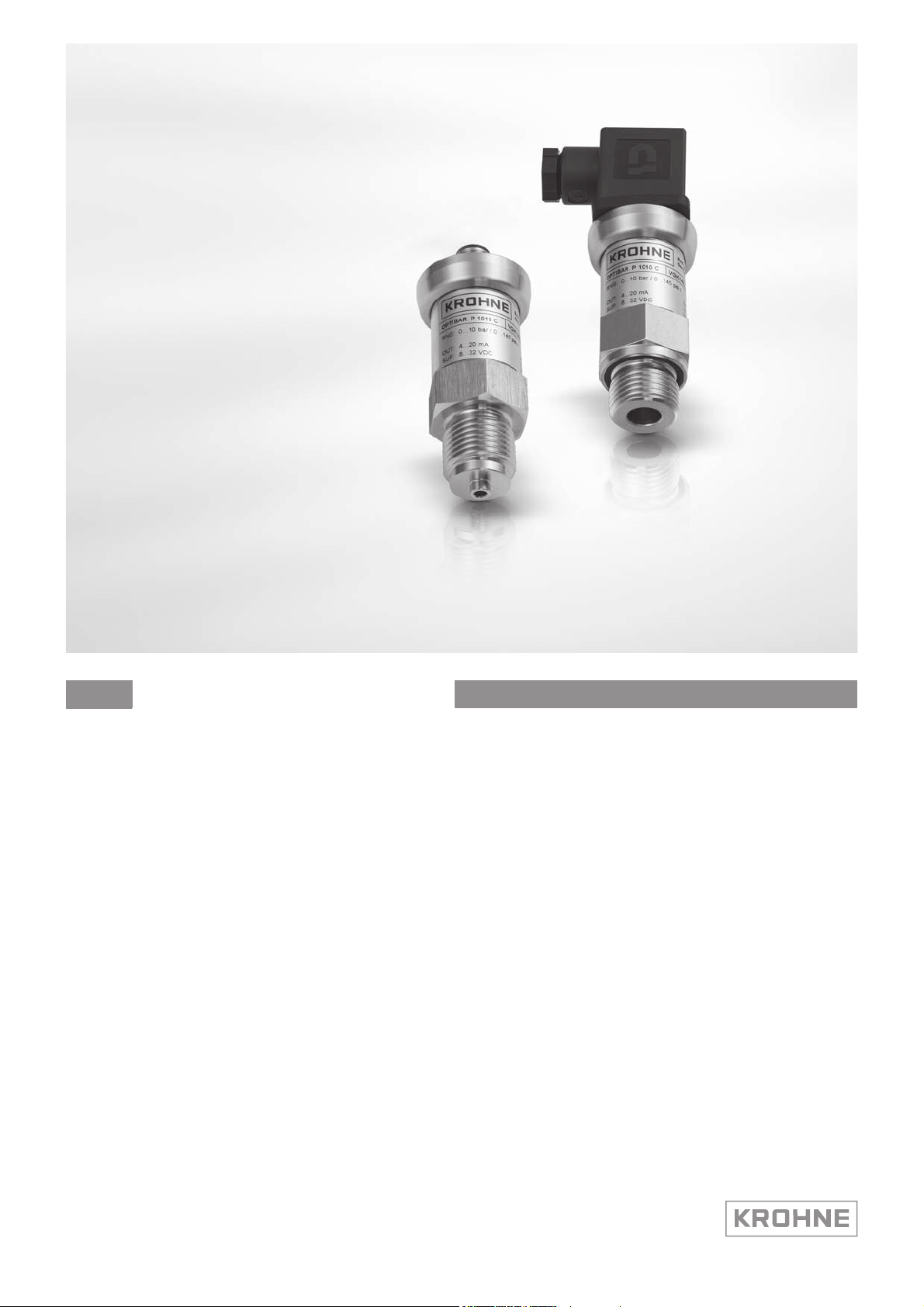
OPTIBAR P 1010 C
OPTIBAR P 1010 C
OPTIBAR P 1010 COPTIBAR P 1010 C
Pressure transmitter with recessed diaphragm for
general applications
HandbookHandbook
© KROHNE 06/2014 - 4002622102 - MA OPTIBAR P1010C R02 en
Page 2

: IMPRINT :::::::::::::::::::::::::::::::::::::::
All rights reserved. It is prohibited to reproduce this documentation, or any part thereof, without
the prior written authorisation of KROHNE Messtechnik GmbH.
Subject to change without notice.
Copyright 2014 by
KROHNE Messtechnik GmbH - Ludwig-Krohne-Str. 5 - 47058 Duisburg (Germany)
2
www.krohne.com 06/2014 - 4002622102 - MA OPTIBAR P1010C R02 en
Page 3

OPTIBAR P 1010 C
CONTENTS
1 Safety instructions 5
1.1 Intended use ..................................................................................................................... 5
1.2 Technical limits ................................................................................................................ 5
1.3 Certification ...................................................................................................................... 5
1.4 Safety instructions from the manufacturer ..................................................................... 6
1.4.1 Copyright and data protection ................................................................................................ 6
1.4.2 Disclaimer ............................................................................................................................... 6
1.4.3 Product liability and warranty ................................................................................................ 7
1.4.4 Information concerning the documentation........................................................................... 7
1.4.5 Warnings and symbols used................................................................................................... 8
1.5 Safety instructions for the operator................................................................................. 8
2 Device description 9
2.1 Scope of delivery............................................................................................................... 9
2.2 Nameplate ...................................................................................................................... 10
3 Installation 11
3.1 General notes on installation ......................................................................................... 11
3.2 Installation specifications .............................................................................................. 11
3.3 Installation...................................................................................................................... 12
3.3.1 Installation steps for connections acc. to DIN 3852............................................................. 13
3.3.2 Installation steps for connections acc. to EN 837 ................................................................ 13
3.3.3 Installation steps for NPT connections ................................................................................13
4 Electrical connections 14
4.1 Safety instructions.......................................................................................................... 14
4.2 Terminal assignment ..................................................................................................... 14
4.3 Electrical connection diagram ....................................................................................... 15
5 Service 16
5.1 Maintenance ................................................................................................................... 16
5.2 Recalibration .................................................................................................................. 16
5.3 Spare parts availability...................................................................................................17
5.4 Availability of services .................................................................................................... 17
5.5 Repairs............................................................................................................................ 17
5.6 Returning the device to the manufacturer..................................................................... 17
5.6.1 General information.............................................................................................................. 17
5.6.2 Form (for copying) to accompany a returned device............................................................ 18
5.7 Disposal .......................................................................................................................... 18
www.krohne.com06/2014 - 4002622102 - MA OPTIBAR P1010C R02 en
3
Page 4

CONTENTS
OPTIBAR P 1010 C
6 Technical data 19
6.1 Technical data................................................................................................................. 19
6.2 Dimensions and weights ................................................................................................ 22
6.3 Measuring ranges with piezoresistive measuring cell.................................................. 25
6.4 Measuring ranges with thin-film measuring cell .......................................................... 25
7 Notes 26
4
www.krohne.com 06/2014 - 4002622102 - MA OPTIBAR P1010C R02 en
Page 5

OPTIBAR P 1010 C
1.1 Intended use
CAUTION!
Responsibility for the use of the measuring devices with regard to suitability, intended use and
corrosion resistance of the used materials against the measured fluid lies solely with the
operator.
INFORMATION!
The manufacturer is not liable for any damage resulting from improper use or use for other than
the intended purpose.
The OPTIBAR P 1010 C
OPTIBAR P 1010 C pressure transmitter is designed to measure the absolute pressure and
OPTIBAR P 1010 COPTIBAR P 1010 C
gauge pressure in gases and liquids.
1.2 Technical limits
The device was constructed solely for use within the technical limits indicated on the nameplate
and in the technical data. Applications outside of these limits are not permitted and could lead to
significant risk of accident. For this reason, observe the following limits:
SAFETY INSTRUCTIONS 1
• Do not exceed the maximum working pressure (MWP).
• Do not exceed the indicated permissible operating temperature range.
• The permissible ambient temperatures given may not be exceeded or undershot.
• Observe the ingress protection of the housing during use.
1.3 Certification
CE marking
The device fulfils the statutory requirements of the following EC directives:
• EMC Directive 2004/108/EC
• EMC specification acc. to EN 61326/A1
The manufacturer certifies successful testing of the product by applying the CE marking.
Pressure equipment directive (PED)
Devices with a permissible pressure PS ≤ 200 bar (20 MPa) comply with Article 3 Section (3) and
are not subject to a conformity assessment. These devices were designed and manufactured in
accordance with sound engineering practice (SEP).
The CE marking on the device does not apply to the Pressure Equipment Directive.
DANGER!
For devices used in hazardous areas, additional safety notes apply; please refer to the Ex
documentation.
www.krohne.com06/2014 - 4002622102 - MA OPTIBAR P1010C R02 en
5
Page 6

1 SAFETY INSTRUCTIONS
1.4 Safety instructions from the manufacturer
1.4.1 Copyright and data protection
The contents of this document have been created with great care. Nevertheless, we provide no
guarantee that the contents are correct, complete or up-to-date.
The contents and works in this document are subject to copyright. Contributions from third
parties are identified as such. Reproduction, processing, dissemination and any type of use
beyond what is permitted under copyright requires written authorisation from the respective
author and/or the manufacturer.
The manufacturer tries always to observe the copyrights of others, and to draw on works created
in-house or works in the public domain.
The collection of personal data (such as names, street addresses or e-mail addresses) in the
manufacturer's documents is always on a voluntary basis whenever possible. Whenever
feasible, it is always possible to make use of the offerings and services without providing any
personal data.
OPTIBAR P 1010 C
We draw your attention to the fact that data transmission over the Internet (e.g. when
communicating by e-mail) may involve gaps in security. It is not possible to protect such data
completely against access by third parties.
We hereby expressly prohibit the use of the contact data published as part of our duty to publish
an imprint for the purpose of sending us any advertising or informational materials that we have
not expressly requested.
1.4.2 Disclaimer
The manufacturer will not be liable for any damage of any kind by using its product, including,
but not limited to direct, indirect or incidental and consequential damages.
This disclaimer does not apply in case the manufacturer has acted on purpose or with gross
negligence. In the event any applicable law does not allow such limitations on implied warranties
or the exclusion of limitation of certain damages, you may, if such law applies to you, not be
subject to some or all of the above disclaimer, exclusions or limitations.
Any product purchased from the manufacturer is warranted in accordance with the relevant
product documentation and our Terms and Conditions of Sale.
The manufacturer reserves the right to alter the content of its documents, including this
disclaimer in any way, at any time, for any reason, without prior notification, and will not be liable
in any way for possible consequences of such changes.
6
www.krohne.com 06/2014 - 4002622102 - MA OPTIBAR P1010C R02 en
Page 7

OPTIBAR P 1010 C
1.4.3 Product liability and warranty
The operator shall bear responsibility for the suitability of the device for the specific purpose.
The manufacturer accepts no liability for the consequences of misuse by the operator. Improper
installation and operation of the devices (systems) will cause the warranty to be void. The
respective "Standard Terms and Conditions" which form the basis for the sales contract shall
also apply.
1.4.4 Information concerning the documentation
To prevent any injury to the user or damage to the device it is essential that you read the
information in this document and observe applicable national standards, safety requirements
and accident prevention regulations.
If this document is not in your native language and if you have any problems understanding the
text, we advise you to contact your local office for assistance. The manufacturer can not accept
responsibility for any damage or injury caused by misunderstanding of the information in this
document.
This document is provided to help you establish operating conditions, which will permit safe and
efficient use of this device. Special considerations and precautions are also described in the
document, which appear in the form of underneath icons.
SAFETY INSTRUCTIONS 1
www.krohne.com06/2014 - 4002622102 - MA OPTIBAR P1010C R02 en
7
Page 8
1 SAFETY INSTRUCTIONS
1.4.5 Warnings and symbols used
Safety warnings are indicated by the following symbols.
DANGER!
This warning refers to the immediate danger when working with electricity.
DANGER!
This warning refers to the immediate danger of burns caused by heat or hot surfaces.
DANGER!
This warning refers to the immediate danger when using this device in a hazardous atmosphere.
DANGER!
These warnings must be observed without fail. Even partial disregard of this warning can lead to
serious health problems and even death. There is also the risk of seriously damaging the device
or parts of the operator's plant.
OPTIBAR P 1010 C
WARNING!
Disregarding this safety warning, even if only in part, poses the risk of serious health problems.
There is also the risk of damaging the device or parts of the operator's plant.
CAUTION!
Disregarding these instructions can result in damage to the device or to parts of the operator's
plant.
INFORMATION!
These instructions contain important information for the handling of the device.
LEGAL NOTICE!
This note contains information on statutory directives and standards.
• HANDLING
HANDLING
HANDLINGHANDLING
This symbol designates all instructions for actions to be carried out by the operator in the
specified sequence.
i RESULT
RESULT
RESULTRESULT
This symbol refers to all important consequences of the previous actions.
1.5 Safety instructions for the operator
WARNING!
In general, devices from the manufacturer may only be installed, commissioned, operated and
maintained by properly trained and authorized personnel.
This document is provided to help you establish operating conditions, which will permit safe and
efficient use of this device.
8
www.krohne.com 06/2014 - 4002622102 - MA OPTIBAR P1010C R02 en
Page 9

OPTIBAR P 1010 C
2.1 Scope of delivery
INFORMATION!
Inspect the packaging carefully for damages or signs of rough handling. Report damage to the
carrier and to the local office of the manufacturer.
INFORMATION!
Do a check of the packing list to make sure that you have all the elements given in the order.
INFORMATION!
Look at the device nameplate to ensure that the device is delivered according to your order.
Check for the correct supply voltage printed on the nameplate.
The following items are supplied with the device:
• Measuring device in ordered version
• For mechanical connections DIN 3852: O-ring (pre-assembled)
• Product documentation
DEVICE DESCRIPTION 2
INFORMATION!
Assembly materials and tools are not part of the delivery. Use the assembly materials and tools
in compliance with the applicable occupational health and safety directives.
www.krohne.com06/2014 - 4002622102 - MA OPTIBAR P1010C R02 en
9
Page 10

2 DEVICE DESCRIPTION
2.2 Nameplate
INFORMATION!
Look at the device nameplate to ensure that the device is delivered according to your order.
Check for the correct supply voltage printed on the nameplate.
The device can be identified by its nameplate. It provides the most important data.
OPTIBAR P 1010 C
Figure 2-1: Example for a nameplate
1 Manufacturer logo and address
2 CE marking and other approvals (e.g. ATEX, PED,...)
3 Serial number
4 Type code
5 Barcode
6 Electrical connection diagram
7 Specifications for process conditions (measuring range, MWP (= Maximum Working Pressure) and electrical data (sig-
nal output and power supply))
8 Product name
10
www.krohne.com 06/2014 - 4002622102 - MA OPTIBAR P1010C R02 en
Page 11

OPTIBAR P 1010 C
3.1 General notes on installation
INFORMATION!
Inspect the packaging carefully for damages or signs of rough handling. Report damage to the
carrier and to the local office of the manufacturer.
INFORMATION!
Do a check of the packing list to make sure that you have all the elements given in the order.
INFORMATION!
Look at the device nameplate to ensure that the device is delivered according to your order.
Check for the correct supply voltage printed on the nameplate.
3.2 Installation specifications
WARNING!
Install the device only when depressurised and without power!
INSTALLATION 3
DANGER!
For installation the respective regulations for explosion protection have to be fulfilled.
INFORMATION!
For installations outdoor and in damp areas, the following points must be observed:
•
To ensure that no moisture can get into the connector, the device should be connected
electrically immediately after installation. Otherwise a moisture admission has to be
prevented e.g. by using a suitable protection cap.
•
Select an installation if possible, where a mounting position allows draining of spray and
condensate. Sealing surfaces should not be submerged!
•
When using devices with cable glands or output, the cable should be looped facing down so
that any liquid that collects on the cable can drip off.
•
Install the device so it is protected from direct sunlight. In the worst case scenario, the
permissible operating temperature will be exceeded in the presence of direct sunlight. This
can negatively affect or damage the functionality of the device. In addition, it can lead to
temporary measuring errors if the internal pressure of the device increases due to the
sunlight.
•
When installing outside where the risk of lightning or overvoltage may exist and damage the
device, we recommend installing suitable overvoltage protection between the supply device
or control cabinet and the device.
www.krohne.com06/2014 - 4002622102 - MA OPTIBAR P1010C R02 en
11
Page 12

3 INSTALLATION
INFORMATION!
•
Handle this highly sensitive electronic measuring device with care, both in and out of the
packaging!
•
Only remove the packaging and any protection cap from the device immediately before
installing to prevent damage to the diaphrahm! Keep the supplied protection cap! Remove the
protection cap slowly and carefully to avoid any negative pressure on the diaphragm.
•
Handle the unprotected diaphragm with extreme care; it is very easily damaged.
•
A device with a gauge reference in the housing (small hole next to the electrical connection)
must be installed so that the gauge reference necessary for measurement is protected from
dirt and moisture. Should the pressure transmitter be exposed to fluid admission, the air
pressure compensation is blocked by the gauge reference. Accurate measurement in this
state is not possible. It can also result in damage to the pressure transmitter.
•
Ensure that no mechanical stress is applied to the pressure port during installation as this
may result in a shift in the characteristic curve. This applies in particular to very small
pressure ranges as well as to devices with plastic pressure ports.
•
With hydraulic systems, arrange the device so that the pressure port faces up (venting).
•
Provide cooling fins when using on steam lines.
3.3 Installation
OPTIBAR P 1010 C
CAUTION!
•
Prior to installing the pressure transmitter, it is essential to verify whether the version of the
device on hand completely fulfils the technical and safety requirements of the measuring
point. This applies in particular to the measuring range, overpressure resistance,
temperature, explosion protection and operating voltage.
•
Check the materials used for the wetted parts (e.g. gasket, process connection, separating
diaphragm etc.) for suitability as regards process compatibility.
12
www.krohne.com 06/2014 - 4002622102 - MA OPTIBAR P1010C R02 en
Page 13

OPTIBAR P 1010 C
3.3.1 Installation steps for connections acc. to DIN 3852
• Make sure that the O-ring fits properly in the intended groove.
• Ensure that the raised face of the receiving part has a smooth surface.
• Screw the device into the thread by hand.
• Devices with wrench flats must be tightened with a wrench. For information on tightening
torque refer to the following table.
Wrench size Tightening torque [Nm]
Wrench size of steel
Wrench size of steel
Wrench size of steelWrench size of steel
G1/4 approx. 5
G1/2 approx. 10
G3/4 approx. 15
G1 approx. 20
G1 1/2 approx. 25
Wrench size of plastic
Wrench size of plastic
Wrench size of plasticWrench size of plastic
All sizes max. 3
INSTALLATION 3
3.3.2 Installation steps for connections acc. to EN 837
• When sealing, use a suitable gasket that corresponds to the product and pressure to be
measured (e.g. a copper gasket).
• Ensure that the raised face of the receiving part has a smooth surface.
• Screw the device into the thread by hand.
• Then tighten the device with the wrench.
Wrench size Tightening torque [Nm]
G1/4 approx. 20
G1/2 approx. 50
3.3.3 Installation steps for NPT connections
• When sealing, use a suitable sealing agent that is compatible with the product (e.g. PTFE
tape).
• Screw the device into the thread by hand.
• Then tighten the device with the wrench.
Wrench size Tightening torque [Nm]
1/4 NPT approx. 30
1/2 NPT approx. 70
www.krohne.com06/2014 - 4002622102 - MA OPTIBAR P1010C R02 en
13
Page 14

4 ELECTRICAL CONNECTIONS
4.1 Safety instructions
DANGER!
All work on the electrical connections may only be carried out with the power disconnected. Take
note of the voltage data on the nameplate!
DANGER!
Observe the national regulations for electrical installations!
DANGER!
For devices used in hazardous areas, additional safety notes apply; please refer to the Ex
documentation.
WARNING!
Observe without fail the local occupational health and safety regulations. Any work done on the
electrical components of the measuring device may only be carried out by properly trained
specialists.
OPTIBAR P 1010 C
INFORMATION!
Look at the device nameplate to ensure that the device is delivered according to your order.
Check for the correct supply voltage printed on the nameplate.
4.2 Terminal assignment
WARNING!
Install the device only when depressurised and without power!
Electrical
connections
- - -
Supply + 1 1 IN + wh (white)
Supply - 2 2 IN - bn (brown)
Shielding Ground contact 4 - gn/ye
ISO 4400 M12x1 (4-pin) Field housing Cable colours
(DIN 47100)
(green/yellow)
14
Devices with cable glands and cable connector
Ensure that the outer diameter of the cable used is within the permissible clamping range. Also
ensure that it is sitting firmly in the cable gland with no gaps!
www.krohne.com 06/2014 - 4002622102 - MA OPTIBAR P1010C R02 en
Page 15

OPTIBAR P 1010 C
Devices with cable output
Observe the following minimum bending radii when laying the cable:
• Cable without venting:
static installation: 5-times the cable diameter
dynamic application: 10-times the cable diameter
• Cable with venting:
static installation: 10-times the cable diameter
dynamic application: 20-times the cable diameter
Devices with cable output and integrated venting
The PTFE filter at the end of the cable on the venting port may not be damaged or removed. For
the electrical connection it is preferable to use a shielded and twisted multicore cable.
Devices with ISO 4400 connector
Ensure that the cable connector is properly installed to guarantee the protection category
indicated! Ensure that the gasket supplied is installed between the plug and the cable connector.
After connecting the cable, fasten the cable connector to the device using the screw.
ELECTRICAL CONNECTIONS 4
Devices with field housing
With these devices, the connection terminals are under the housing cover. To electrically
connect the device, the cover must first be unscrewed. Before screwing the cover back on, check
the O-ring and raised face on the housing for damage and replace if necessary! Screw the cover
back on by hand and ensure that the field housing is firmly closed.
4.3 Electrical connection diagram
Figure 4-1: Electrical connection diagram
1 Supply +
2 Supply -
3 Shielding
4 Supply voltage V
S
www.krohne.com06/2014 - 4002622102 - MA OPTIBAR P1010C R02 en
15
Page 16

5 SERVICE
5.1 Maintenance
In principal, the device is maintenance free. If necessary, clean the device housing when
switched off using a damp cloth and a non-aggressive cleaning solution.
Depending on the product, deposits or contamination can still occur on the diaphragm. If the
product has a known affinity, the operator must determine the cleaning intervals accordingly.
Once the device has been properly taken out of commission, the diaphragm can generally be
carefully cleaned using a non-aggressive cleaning solution and a soft brush or sponge. If the
diaphragm is calcified, decalcification by the manufacturer is recommended.
INFORMATION!
Improper cleaning can result in irreparable damage to the measuring cell. For this reason,
never use sharp objects or compressed air to clean the diaphragm.
5.2 Recalibration
During the life cycle of the device, the offset or full-scale of the device may shift. If this occurs,
note that the signal value output will deviate based on the set start or end value of the measuring
range. If one of these phenomena does occur following prolonged use, recalibration is
recommended to ensure continued high accuracy.
OPTIBAR P 1010 C
16
www.krohne.com 06/2014 - 4002622102 - MA OPTIBAR P1010C R02 en
Page 17

OPTIBAR P 1010 C
5.3 Spare parts availability
The manufacturer adheres to the basic principle that functionally adequate spare parts for each
device or each important accessory part will be kept available for a period of 3 years after
delivery of the last production run for the device.
This regulation only applies to spare parts which are subject to wear and tear under normal
operating conditions.
5.4 Availability of services
The manufacturer offers a range of services to support the customer after expiration of the
warranty. These include repair, maintenance, technical support and training.
INFORMATION!
For more precise information, please contact your local sales office.
5.5 Repairs
SERVICE 5
Repairs may be carried out exclusively by the manufacturer or the manufacturer authorised
specialist companies.
5.6 Returning the device to the manufacturer
5.6.1 General information
This device has been carefully manufactured and tested. If installed and operated in accordance
with these operating instructions, it will rarely present any problems.
CAUTION!
Should you nevertheless need to return a device for inspection or repair, please pay strict
attention to the following points:
•
Due to statutory regulations on environmental protection and safeguarding the health and
safety of our personnel, manufacturer may only handle, test and repair returned devices that
have been in contact with products without risk to personnel and environment.
•
This means that the manufacturer can only service this device if it is accompanied by the
following certificate (see next section) confirming that the device is safe to handle.
CAUTION!
If the device has been operated with toxic, caustic, flammable or water-endangering products,
you are kindly requested:
•
to check and ensure, if necessary by rinsing or neutralising, that all cavities are free from
such dangerous substances,
•
to enclose a certificate with the device confirming that is safe to handle and stating the
product used.
www.krohne.com06/2014 - 4002622102 - MA OPTIBAR P1010C R02 en
17
Page 18

5 SERVICE
5.6.2 Form (for copying) to accompany a returned device
Company: Address:
Department: Name:
Tel. no.: Fax no.:
Manufacturer's order no. or serial no.:
The device has been operated with the following medium:
OPTIBAR P 1010 C
This medium is: radioactive
water-hazardous
toxic
caustic
flammable
We checked that all cavities in the device are free from such
substances.
We have flushed out and neutralized all cavities in the
device.
We hereby confirm that there is no risk to persons or the environment through any residual media
contained in the device when it is returned.
Date: Signature:
Stamp:
5.7 Disposal
CAUTION!
Disposal must be carried out in accordance with legislation applicable in your country.
18
www.krohne.com 06/2014 - 4002622102 - MA OPTIBAR P1010C R02 en
Page 19

OPTIBAR P 1010 C
TECHNICAL DATA 6
6.1 Technical data
INFORMATION!
•
The following data is provided for general applications. If you require data that is more
relevant to your specific application, please contact us or your local sales office.
•
Additional information (certificates, special tools, software,...) and complete product
documentation can be downloaded free of charge from the website (Download Center).
Measuring system
Measuring principle Piezoresistive measuring cell up to 40 bar / 580 psi
Thin-film measuring cell from 60 bar / 870 psi
Application range Measurement of gauge and absolute pressure in gases and liquids
Measuring range Fixed 0.1...600 bar / 1.5...8700 psi; refer also to chapter "Measuring ranges"
Measuring accuracy
Reference conditions Medium: air
Temperature: ambient temperature
Ambient pressure: 1013 mbar / 14.7 psi
Nominal position: vertical, pressure port down
Power supply: 24 VDC
Pressure type Gauge pressure / absolute pressure
Measuring accuracy according to
IEC 60770 (terminal based)
(Hysteresis, non-linearity, nonrepeatability)
Ambient temperature effect on
zero and span
Nominal pressure (P
Nominal pressure (P
(URL = Upper Range Limit)
Nominal pressure (PN) < 0.4 bar / 5.8 psi:
≤± 1.5% of URL in compensated range of 0...+50°C / +32...+122°F
) < 0.4 bar / 5.8 psi: ≤± 0.5% of URL
N
) > 0.4 bar / 5.8 psi: ≤± 0.25% of URL
N
Nominal pressure (P
≤± 0.75% of URL in compensated range of -20...+85°C / -4...+185°F
Nominal pressure (P
Long-term stability ≤±0.1% of URL within one year under reference conditions
Step response time < 10 ms (T90)
Vacuum resistance PN ≥ 1 bar / 14.5 psi: vacuum resistant
< 1 bar / 14.5 psi: on request
P
N
) > 0.4 bar / 5.8 psi:
N
) = -1...0 bar / -14.5...0 psi: ≤± 0.75% of URL
N
www.krohne.com06/2014 - 4002622102 - MA OPTIBAR P1010C R02 en
19
Page 20

6 TECHNICAL DATA
Operating conditions
Temperature
Temperature
TemperatureTemperature
Nominal temperature -20...+80°C / -4...+176°F
Ambient temperature -40…+85°C / -40...+185°F
Ex i zone 0: -20...+60°C / -4...+140°F at p
Ex i from zone 1: -20...+70°C / -4...+158°F
Storage temperature -40…+100°C / -40...+212°F
Medium temperature P
Other conditions
Other conditions
Other conditionsOther conditions
Ingress protection acc. to IEC
529 / EN 60529
≤ 40 bar / 580 psi: -40...+125°C / -40...+257°F
N
P
≥ 60 bar / 870 psi: -25...+125°C / -13...+257°F
N
With cooling fins (optional):
P
> 0 barg: -40...+200°C / -40...+392°F;
N
P
< 0 barg: -40...+150°C / -40...+302°F
N
Connector M16 ISO 4400: IP65
Connector M12x1, 4-pin: IP67
Cable PUR: IP67
Cable PUR with venting: IP68 (1mWS / 24h)
Thread M12, housing in 1.4404 / AISI 316L: IP67
= 0.8...1.1 bar
abs
OPTIBAR P 1010 C
Installation conditions
Mounting position Any - factory calibration carried out with pressure port down.
Dimensions For detailed information refer to chapter "Dimensions and weights".
Weight Min. 200 g / 0.44 lb (depending on pressure port)
Materials
Housing Stainless steel 1.4404 / AISI 316L
Field housing (optional): stainless steel 1.4301 / AISI 304
Cable gland Nickel-plated brass
Fill fluid Silicone oil (PN ≤ 40 bar / 580 psi)
Without (PN ≥ 60 bar / 870 psi)
Wetted parts
Wetted parts
Wetted partsWetted parts
Pressure port Stainless steel 1.4404 / AISI 316L
Separating diaphragm Stainless steel 1.4435 / AISI 316L
Sealing FKM (medium temperature ≤ +200°C / +392°F); EPDM; NBR
20
www.krohne.com 06/2014 - 4002622102 - MA OPTIBAR P1010C R02 en
Page 21

OPTIBAR P 1010 C
TECHNICAL DATA 6
Process connections
Thread Thread ANSI 1/2 NPT-M; thread ANSI 1/4 NPT-M
Thread ISO 228 G1/2, EN 837-1; thread ISO 228 G1/2, 10 mm bore, DIN 3852; thread
ISO 228 G1/4, EN 837-1; thread ISO 228 G1/4, DIN 3852
Electrical connection
Output signal 4...20 mA current output; 2-wire
Power supply Standard: Ub = 8...32 VDC
Ex i: Ub = 10 ... 28 VDC
Safety maximum values (Ex i) Ui = 28 V, Ii = 93 mA, Pi = 660 mW, Ci ≈ 0 nF, Li ≈ 0 μH;
The supply connections have a maximum internal capacity of 27 nF to the housing.
Load R
Short circuit protection Continuously
Reverse polarity protection In the event of reversed connections there is no damage but also no function.
Ripple 0.05% of URL / 10 V
Electrical connection Connector M16 ISO 4400
≤ (Ub - U
lmax
Connector M12x1, 4-pin
Cable PUR
Cable PUR with venting
Thread M12, housing 316L
) / 0.02 A [Ohm]
bmin
Approvals and certificates
CE The device fulfils the statutory requirements of the EC directives. The manufacturer
Electromagnetic compatibility
(EMC) acc. to EN 61326
Pressure equipment directive 97/23/EC
Ex
Ex
ExEx
ATEX II 1G Ex ia IIC T4 or II 1D Ex ia T85°C
IECEx Ex ia IIC T4 Ga or Ex ia IIIC T85°C Da
Other standards and approvals
Other standards and approvals
Other standards and approvalsOther standards and approvals
Vibration resistance acc. to
EN 60068-2-6
Shock resistant (impact)
according to EN 60068-2-27
certifies that these requirements have been met by applying the CE marking.
EMC Directive: 2004/108/EC
For more information consult the relevant declaration of conformity.
10g RMS (25...2000 Hz)
500g / 1 ms (PN ≤ 40 bar / 580 psi)
100g / 11 ms (PN ≥ 60 bar / 870 psi)
www.krohne.com06/2014 - 4002622102 - MA OPTIBAR P1010C R02 en
21
Page 22

6 TECHNICAL DATA
6.2 Dimensions and weights
Connection plug and field housing
OPTIBAR P 1010 C
Figure 6-1: Dimensions for connection plug and field housing
1 ISO 4400 (cable connector is part of delivery)
2 M12x1 (4-pin)
3 Cable output
4 Cable output, cable with venting
5 Field housing
Dimensions
1 2 3 4 5
[mm] ["] [mm] ["] [mm] ["] [mm] ["] [mm] ["]
a 10.5 0.4 10.5 0.4 10.5 0.4 10.5 0.4 48 1.9
b 12 0.47 10 0.39 Ø4.3 Ø0.17 7.4 0.29 Ø49.5 Ø1.95
c Ø34.5 Ø1.36 Ø34.5 Ø1.36 Ø35 Ø1.38 Ø35 Ø1.38 44 1.7
d - - - - 15 0.59 15 0.59 M12x1.5
22
www.krohne.com 06/2014 - 4002622102 - MA OPTIBAR P1010C R02 en
Page 23

OPTIBAR P 1010 C
Pressure transmitter with threaded connection (ISO 228)
TECHNICAL DATA 6
Figure 6-2: Dimensions for pressure transmitter with threaded connection (ISO 228)
1 G1/2 DIN 3852
2 G1/2 EN 837
3 G1/2 open connection (10 mm / 0.39" bore)
4 G1/4 DIN 3852
5 G1/4 EN 837
Dimensions
1 2 3 4 5
[mm] ["] [mm] ["] [mm] ["] [mm] ["] [mm] ["]
e 50 2 50 2 50 2 50 2 50 2
h G1/2 G1/2 G1/2 G1/4 G1/4
k 17 0.67 23 0.9 17 0.67 14 0.55 15 0.59
m 14 0.55 3 0.12 14 0.55 12 0.47 2 0.08
n - - - - 21 0.83 - - - -
0 - - - - Ø10 Ø0.39 - - - -
p - - - - - - - - - -
The entire length of the device is made up of the electrical connection (a), the transmitter
housing (e) and the process connection (k).
With cooling fins (optional) additional 32 mm / 1.26".
www.krohne.com06/2014 - 4002622102 - MA OPTIBAR P1010C R02 en
23
Page 24

6 TECHNICAL DATA
Pressure transmitter with cooling fins and threaded connection (ANSI)
Figure 6-3: Dimensions for pressure transmitter with cooling fins and threaded connection (ANSI)
1 Cooling fins (optional)
2 Thread ANSI 1/4 NPT-M
3 Thread ANSI 1/2 NPT-M
OPTIBAR P 1010 C
Dimensions
1 2 3
[mm] ["] [mm] ["] [mm] ["]
e 50 2 50 2 50 2
h - 1/4 NPT 1/2 NPT
k - - 14 0.55 20 0.79
r 32 1.26 - - - -
The entire length of the device is made up of the electrical connection (a), the transmitter
housing (e) and the process connection (k).
With cooling fins (optional) additional 32 mm / 1.26".
24
www.krohne.com 06/2014 - 4002622102 - MA OPTIBAR P1010C R02 en
Page 25

OPTIBAR P 1010 C
TECHNICAL DATA 6
6.3 Measuring ranges with piezoresistive measuring cell
Pressure in bar
Nominal pressure
(gauge/abs.)
Max. working pressure
(MWP)
Burst pressure (OPL) 7.5 1.5 1.5 1.5 3 7.5 7.5 15
Nominal pressure
(gauge/abs.)
Max. working pressure
(MWP)
Burst pressure (OPL) 15 25 50 50 120 120 210
-1...0 0.10 0.16 0.25 0.40 0.60 1 1.6
5 0.5 1 1 2 5 5 10
2.5 4 6 10 16 25 40
10 20 40 40 80 80 105
Pressure in psi
Nominal pressure
(gauge/abs.)
Max. working pressure
(MWP)
Burst pressure (OPL) 108.8 21.8 21.8 21.8 43.5 108.8 108.8 217.6
Nominal pressure
(gauge/abs.)
Max. working pressure
(MWP)
Burst pressure (OPL) 217.6 362.6 725 725 1740 1740 3046
-14.5...0 1.45 2.32 3.63 5.80 8.70 14.5 23.2
72.5 7.3 14.5 14.5 29 72.5 72.5 145
36.3 58.0 87.0 145 232.1 362.6 580
145 290 580 580 1160 1160 1523
6.4 Measuring ranges with thin-film measuring cell
Pressure in bar
Nominal pressure
(gauge/abs.)
Max. working pressure
(MWP)
Burst pressure (OPL) 420 1000 1000 1250 1250 1250
Pressure in psi
Nominal pressure
(gauge/abs.)
Max. working pressure
(MWP)
Burst pressure (OPL) 6092 14500 14500 18130 18130 18130
60 100 160 250 400 600
210 600 600 1000 1000 1000
870 1450 2321 3626 5800 8700
3046 8702 8702 14500 14500 14500
www.krohne.com06/2014 - 4002622102 - MA OPTIBAR P1010C R02 en
25
Page 26

7 NOTES
OPTIBAR P 1010 C
26
www.krohne.com 06/2014 - 4002622102 - MA OPTIBAR P1010C R02 en
Page 27

OPTIBAR P 1010 C
NOTES 7
www.krohne.com06/2014 - 4002622102 - MA OPTIBAR P1010C R02 en
27
Page 28

KROHNE product overview
• Electromagnetic flowmeters
• Variable area flowmeters
• Ultrasonic flowmeters
• Mass flowmeters
• Vortex flowmeters
• Flow controllers
• Level meters
• Temperature assemblies
• Pressure transmitters
• Analysis products
• Products and systems for the oil & gas industry
• Measuring systems for the marine industry
Head Office KROHNE Messtechnik GmbH
Ludwig-Krohne-Str. 5
47058 Duisburg (Germany)
Tel.:+49 203 301 0
Fax:+49 203 301 103 89
info@krohne.com
© KROHNE 06/2014 - 4002622102 - MA OPTIBAR P1010C R02 en - Subject to change without notice.
The current list of all KROHNE contacts and addresses can be found at:
www.krohne.com
 Loading...