

Page 1

Technical Datasheet
Technical Datasheet
OPTIWAVE 7300 C
OPTIWAVE 7300 C
OPTIWAVE 7300 COPTIWAVE 7300 C
Technical DatasheetTechnical Datasheet
24 GHz Non-contact Radar (FMCW) Level Meter
•
For liquid applications
•
The only guarantee for measuring accurately in difficult conditions
•
Antenna options (Drop, Hygienic, etc.) designed for specific purposes
© KROHNE 03/2015 - 4000112308 - TD OPTIWAVE 7300 R13 en
Page 2

CONTENTS
OPTIWAVE 7300 C
1 Product features 3
1.1 The radar solution for liquids........................................................................................... 3
1.2 Applications ...................................................................................................................... 5
1.3 Measuring principle.......................................................................................................... 7
2 Technical data 8
2.1 Technical data................................................................................................................... 8
2.2 Antenna selection........................................................................................................... 14
2.3 Guidelines for maximum operating pressure................................................................ 15
2.4 Dimensions and weights ................................................................................................ 17
3 Installation 29
3.1 Intended use ................................................................................................................... 29
3.2 Pre-installation requirements ....................................................................................... 29
3.3 How to prepare the tank before you install the device .................................................. 30
3.3.1 Recommended mounting position........................................................................................ 30
3.3.2 Theoretical data for hygienic applications ........................................................................... 31
3.4 Installation recommendations for liquids...................................................................... 32
3.4.1 General requirements .......................................................................................................... 32
3.4.2 Standpipes (stilling wells and bypass chambers) ................................................................ 33
3.5 How to install the device on the tank ............................................................................. 37
3.5.1 How to install a device with a flange connection ................................................................. 37
3.5.2 How to install a device with a threaded connection............................................................. 37
3.5.3 How to install a device with a hygienic connection .............................................................. 38
4 Electrical connections 41
4.1 Safety instructions.......................................................................................................... 41
4.2 Electrical installation: outputs 1 and 2 .......................................................................... 41
4.2.1 Non-Ex devices ..................................................................................................................... 42
4.2.2 Devices for hazardous locations........................................................................................... 42
4.3 Protection category ........................................................................................................43
4.4 Networks ........................................................................................................................ 44
4.4.1 General information.............................................................................................................. 44
4.4.2 Point-to-point connection..................................................................................................... 44
4.4.3 Multi-drop networks ............................................................................................................. 45
5 Order information 46
5.1 Order code ...................................................................................................................... 46
2
www.krohne.com 03/2015 - 4000112308 - TD OPTIWAVE 7300 R13 en
Page 3

OPTIWAVE 7300 C
1.1 The radar solution for liquids
This device is a non-contact Radar (FMCW) Level Meter for distance, level, volume and mass
measurement of liquids, pastes and slurries. It gives a stabler measurement than pulse radar
and is well suited to agitated process conditions. The device can operate at very low and very
high process temperatures as long as the process connection temperature limits are observed.
PRODUCT FEATURES
1
1 Optional touch screen with 4-button operation
2 2-wire level meter
3 One converter for all applications
4 Stainless steel horn, PTFE/PP Drop or PEEK Hygienic antenna
5 Antenna extension (for long nozzles)
6 Optional Metaglas® barrier
7 Rotatable housing
8 One converter for all applications
www.krohne.com03/2015 - 4000112308 - TD OPTIWAVE 7300 R13 en
3
Page 4

1
PRODUCT FEATURES
Highlights
• ±3mm/ ±0.12¨ standard accuracy
• Optionally equipped with a 4-button touch screen display and an easy-to-use setup wizard
• Reliable measurement in difficult process conditions
• Operates up to a process connection temperature of +200°C / +390°F and 100 barg / 1450 psig
for standard applications, and up to +570°C / +1058°F for molten salt applications
• Measuring range up to 80 m / 260 ft
• Horn and Drop antenna versions can be extended to suit any nozzle length
• Drop antenna for corrosive liquids (with optional PTFE/PP flange plate) or where product
build-up is likely to occur
• Sealed Drop antenna extension option for pressurized tanks
• Hygienic antenna for processes where stringent hygiene standards must be obeyed
• PACTware and DTMs included as standard
• Optional second current output
• Directly-accessible graphic touchscreen/wizard (option)
• Converter rotates 360°
• Triple barrier gas-tight protection available for working with dangerous gases
(using pre-stressed fused glass)
• Fast motion software that can measure 5 times per second for wave height measurement
OPTIWAVE 7300 C
Industries
• Chemicals
• Food & Beverage
• Oil & Gas
• Petrochemicals
• Pharmaceutical
• Pulp & Paper
• Water & Wastewater
Applications
• Tanks with agitators
• Process tanks
• Storage tanks
• Torpedo ladles (foundries)
• Wave height
4
www.krohne.com 03/2015 - 4000112308 - TD OPTIWAVE 7300 R13 en
Page 5

OPTIWAVE 7300 C
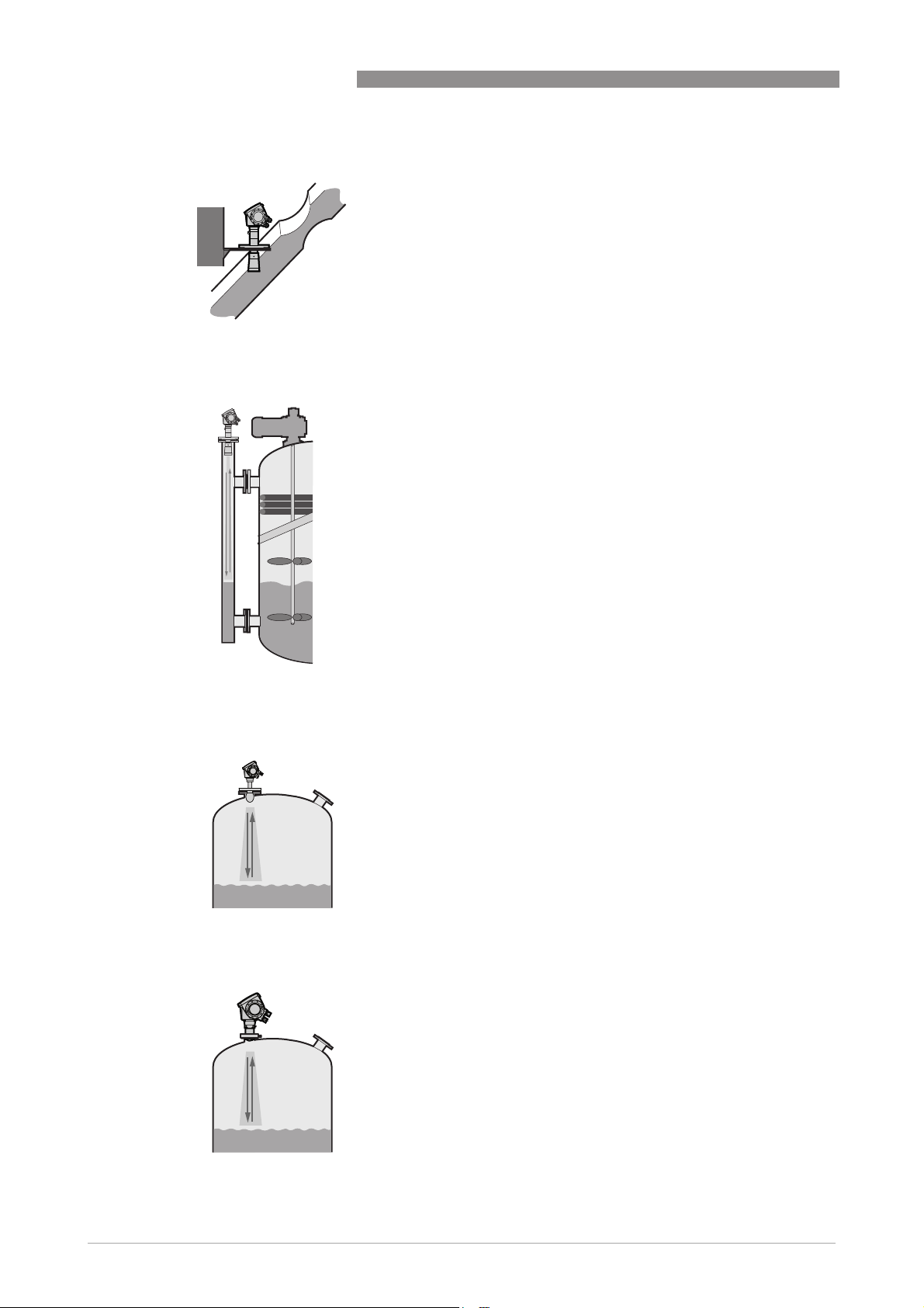
1.2 Applications
1. Level measurement of liquids in storage tanks
2. Level measurement of liquids in process tanks
PRODUCT FEATURES
The level transmitter can measure the level of a
wide range of liquid products on a large variety of
installations, including LPG and LNG tanks. It does
not require calibration or commissioning when
installed. It can measure any liquid within the stated
pressure and temperature range, and distances up
to 80 m / 260 ft.
The level transmitter can measure level accurately
in agitated conditions, such as near to vortexes
caused by agitators, and also where foam is present.
1
3. Wave height measurement
The fast motion software option permits the device
to measure 5 times per second. The device can
follow fast changes in the height of surface waves in
oceans and lakes. This software also permits the
device to monitor torpedo ladle filling operations in
steel mills.
www.krohne.com03/2015 - 4000112308 - TD OPTIWAVE 7300 R13 en
5
Page 6
1
PRODUCT FEATURES
4. Open channel metering or flow
5. Measurement of liquids in a bypass chamber
OPTIWAVE 7300 C
The level transmitter can measure level in an open
channel and convert this measurement into flow
values if the characteristics of the channel are
known. This solution is the high-end alternative to
ultrasonic and hydrostatic pressure transmitters.
If the tank is full of obstructions such as agitators
and reinforcements, we recommend installing the
radar level transmitter in a bypass chamber or a
stilling well. This solution is also available from us
under the name BM 26 W. The BM 26 W combines
the BM 26 A with the radar level transmitter. The
device includes a permanent, local indication
without a power supply. Please refer to the BM 26 W
documentation for further information.
6. Measurement of corrosive liquids with a Drop antenna
The Drop antenna option combines a relatively small
radar beam for more precise measurement and a
shape that avoids product build-up. If the tank
contains corrosive liquids such as acids and alkaline
solutions, we recommend the DN80 / 3¨ Drop
antenna with the PTFE or PP flange plate protection
option.
7. Measurement of liquids with a Hygienic antenna
The Hygienic antenna option is made of materials
that agree with FDA regulations. It is suitable for
level measurement in processes that require
hygienic equipment (such as the food, beverage and
pharmaceutical industries).
6
www.krohne.com 03/2015 - 4000112308 - TD OPTIWAVE 7300 R13 en
Page 7
OPTIWAVE 7300 C
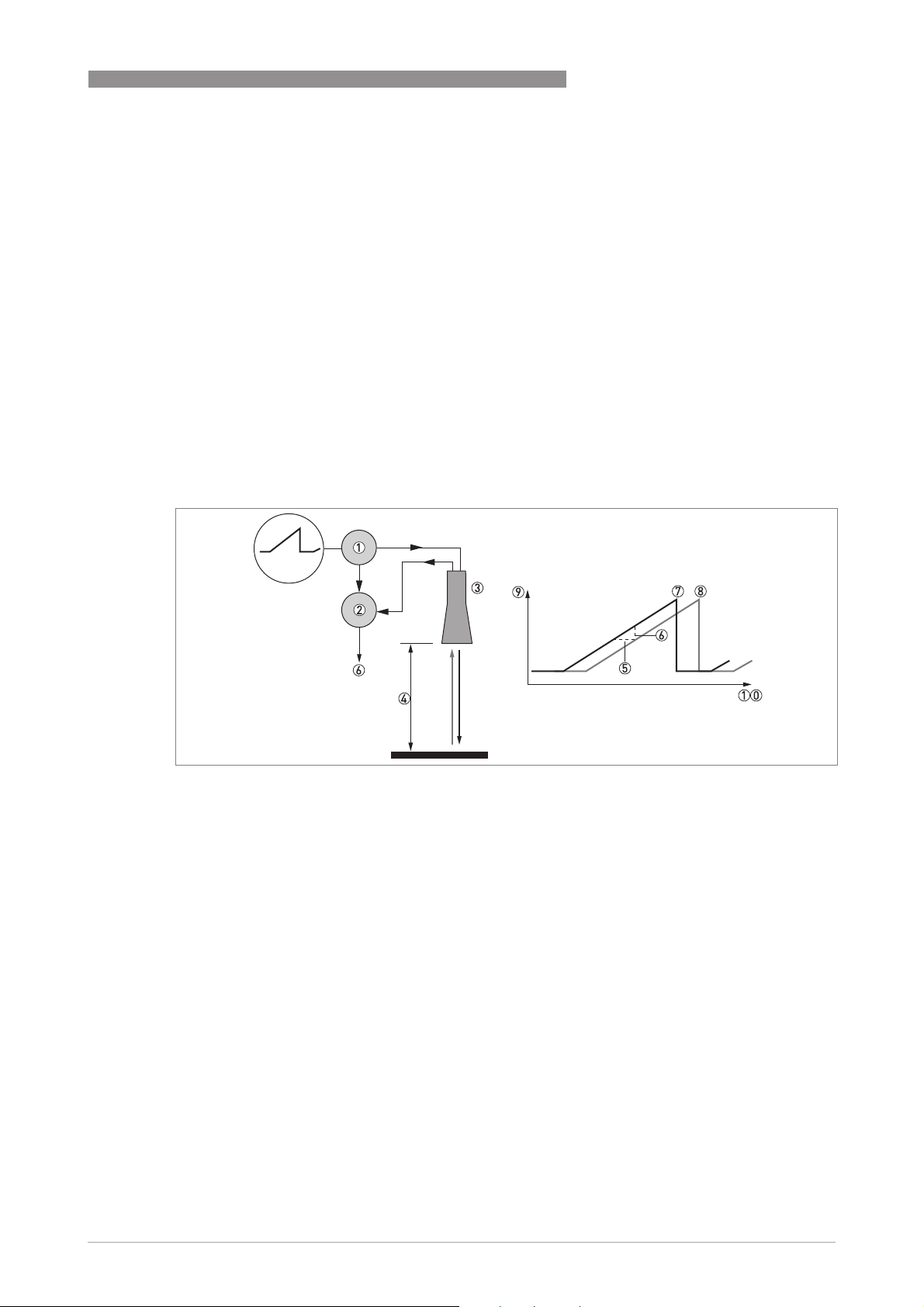
1.3 Measuring principle
A radar signal is emitted via an antenna, reflected from the product surface and received after a
time t. The radar principle used is FMCW (Frequency Modulated Continuous Wave).
The FMCW-radar transmits a high frequency signal whose frequency increases linearly during
the measurement phase (called the frequency sweep). The signal is emitted, reflected on the
measuring surface and received with a time delay, t. Delay time, t=2d/c, where d is the distance
to the product surface and c is the speed of light in the gas above the product.
For further signal processing the difference Δf is calculated from the actual transmitted
frequency and the received frequency. The difference is directly proportional to the distance. A
large frequency difference corresponds to a large distance and vice versa. The frequency
difference Δf is transformed via a Fourier transformation (FFT) into a frequency spectrum and
then the distance is calculated from the spectrum. The level results from the difference between
tank height and measuring distance.
PRODUCT FEATURES
1
Figure 1-1: Measuring principle of FMCW radar
1 Transmitter
2 Mixer
3 Antenna
4 Distance to product surface, where change in frequency is proportional to distance
5 Differential time delay, Δt
6 Differential frequency, Δf
7 Frequency transmitted
8 Frequency received
9 Frequency
10 Time
www.krohne.com03/2015 - 4000112308 - TD OPTIWAVE 7300 R13 en
7
Page 8

2
TECHNICAL DATA
OPTIWAVE 7300 C
2.1 Technical data
•
The following data is provided for general applications. If you require data that is more
relevant to your specific application, please contact us or your local sales office.
•
Additional information (certificates, special tools, software,...) and complete product
documentation can be downloaded free of charge from the website (Download Center).
Measuring system
Measuring principle 2-wire loop-powered level transmitter; K-band (24...26 GHz) FMCW radar
Application range Level measurement of liquids, pastes and slurries
Primary measured value Δf (change in frequency) between the emitted and received signal
Secondary measured value Distance, level, volume, mass and reflectivity
Design
Construction The measurement system consists of a measuring sensor (antenna) and a signal
Options Integrated LCD display with sun cover (-20..+60°C/ -4…+140°F); if the ambient
Accessories Weather protection
Max. measuring range 80 m / 260 ft
Min. tank height 0.2 m / 8¨ (1 m / 40¨ for hygienic antenna)
Max. change in level Standard software: 1...10 m/minute / 3.3...32.8 ft/minute
Min. dead zone Antenna extension length + antenna length + 0.1 m / 4¨ (200 mm / 8¨ for the hygienic
converter which is only available in a compact version
temperature is not in these limits, the display switches off
2nd current output
Fast motion software (5 measurements per second)
PTFE/PP flange plate protection (for Drop antennas without antenna extensions
only)
Distance piece (for process connection temperature: +150...+200°C / +300...+390°F)
1
Antenna purging system (supplied with a ¼ NPTF connection)
Antenna extensions of 105 mm / 4.1¨ length (Max. length for Drop antenna versions:
525 mm / 20.7¨; not available for the Hygienic antenna)
Discs (low-pressure flanges) with bolt hole dimensions and positions that agree
with DN80...200 in PN2.5...40 or 3¨...8¨ in 150 lb for devices with the G 1½ threaded
connection. Max. pressure: 1 barg / 14.5 psig at +20°C / +68°F.
Depends on the antenna option, dielectric constant of the product and installation
type. Refer also to "Antenna selection".
Fast motion software: The device uses strongest signal in the measuring range to
calculate the distance for each measurement cycle. The menu item for tracing
velocity is available, but the function is disabled and changes have no effect on the
performance of the device.
antenna)
8
www.krohne.com 03/2015 - 4000112308 - TD OPTIWAVE 7300 R13 en
Page 9

OPTIWAVE 7300 C
Beam angle of antenna Horn DN40 / 1.5¨: 20°
Horn DN50 / 2¨: 15°
Horn / Sheet metal horn DN80 / 3¨: 10°
Horn / Sheet metal horn DN100 / 4¨: 8°
Sheet metal horn DN150 / 6¨: 6°
Sheet metal horn DN200 / 8¨: 4°
Drop DN80 / 3¨: 8°
Drop DN150 / 6¨: 4°
Hygienic DN50 / 2¨: 15°
Display and user interface
Display and user interface
Display and user interfaceDisplay and user interface
Display LCD display
9 lines, 160 × 160 pixels in 8-step grayscale with 4-button keypad
Interface languages English, German, French, Italian, Spanish, Portuguese, Japanese, Simplified
Chinese and Russian
TECHNICAL DATA
Measuring accuracy
Resolution 1mm/ 0.04¨
Repeatability ±1mm/ ±0.04¨
Accuracy ±3mm/ ±0.12¨, when distance <10m/ 33ft;
Reference conditions acc. to EN 60770
Reference conditions acc. to EN 60770
Reference conditions acc. to EN 60770Reference conditions acc. to EN 60770
Temperature +20°C ±5°C / +70°F ±10°F
Pressure 1013 mbara ±20 mbar / 14.69 psia ±0.29 psi
Relative air humidity 60% ±15%
Target Metal plate in an anechoic chamber
±0.03% of measured distance, when distance > 10 m / 33 ft
2
Operating conditions
Temperature
Temperature
TemperatureTemperature
Ambient temperature -40…+80°C/ -40…+175°F (according to the temperature limits of the gasket
Storage temperature -40…+85°C/ -40…+185°F
Process connection temperature Horn / Sheet metal horn antenna:
material. Refer to "Materials" in this table.)
Ex: see supplementary operating instructions or approval certificates
Horn / Sheet metal horn antenna:
Horn / Sheet metal horn antenna:Horn / Sheet metal horn antenna:
Standard: -50…+150°C/ -58…+300°F
Option: -50…+200°C/ -58…+390°F
(the process connection temperature must agree with the temperature limits of the
gasket material. Refer to "Materials" in this table.)
Ex: see supplementary operating instructions or approval certificates
Drop antenna (PTFE):
Drop antenna (PTFE):
Drop antenna (PTFE):Drop antenna (PTFE):
-50…+150°C/ -58…+300°F (the process connection temperature must agree with
the temperature limits of the gasket material. Refer to "Materials" in this table.)
Ex: see supplementary operating instructions or approval certificates
Drop antenna (PP):
Drop antenna (PP):
Drop antenna (PP):Drop antenna (PP):
-40…+100°C/ -40…+210°F (the process connection temperature must agree with
the temperature limits of the gasket material. Refer to "Materials" in this table.)
Ex: see supplementary operating instructions or approval certificates
Hygienic antenna (PEEK):
Hygienic antenna (PEEK):
Hygienic antenna (PEEK):Hygienic antenna (PEEK):
-20…+150°C/ -4…+300°F (the process connection temperature must agree with
the temperature limits of the gasket material. Refer to "Materials" in this table.)
Ex: see supplementary operating instructions or approval certificates
www.krohne.com03/2015 - 4000112308 - TD OPTIWAVE 7300 R13 en
9
Page 10

2
TECHNICAL DATA
Pressure
Pressure
PressurePressure
Operating pressure Drop antenna (PP):
Other conditions
Other conditions
Other conditionsOther conditions
Dielectric constant (εr) ≥1.5
Vibration resistance IEC 60068-2-6 and EN 50178 (10...57 Hz: 0.075 mm / 57...150 Hz:1g)
Ingress protection IP66/67 equivalent to NEMA type 4X (housing) and type 6P (antenna)
Drop antenna (PP):
Drop antenna (PP):Drop antenna (PP):
-1…16 barg / -14.5…232 psig;
subject to process connection used and flange temperature
Drop antenna (PTFE):
Drop antenna (PTFE):
Drop antenna (PTFE):Drop antenna (PTFE):
-1…40 barg / -14.5…580 psig;
subject to process connection used and flange temperature
Hygienic antenna (PEEK):
Hygienic antenna (PEEK):
Hygienic antenna (PEEK):Hygienic antenna (PEEK):
-1…10 barg / -14.5…145 psig;
subject to process connection used and flange temperature
Horn / Sheet metal horn antenna:
Horn / Sheet metal horn antenna:
Horn / Sheet metal horn antenna:Horn / Sheet metal horn antenna:
Standard: -1…40 barg / -14.5…580 psig;
Option: -1…100 barg / -14.5…1450 psig;
subject to process connection used and flange temperature
OPTIWAVE 7300 C
Installation conditions
Process connection size The nominal diameter (DN) should be equal to or larger than the antenna diameter.
If the nominal diameter (DN) is smaller than the antenna, either:
– provide the means to adapt the device to a larger process connection on the tank
(for example, a plate with a slot), or
– use the same process connection, but remove the antenna from the device before
installation and fit it from inside the tank.
Process connection position Make sure that there are not any obstructions directly below the process
Dimensions and weights Refer to "Technical data: Dimensions and weights".
connection for the device.
Materials
Housing Standard: Polyester-coated aluminium
Option: Stainless steel (1.4404 / 316L)
Wetted parts, including antenna Standard for Horn / Sheet metal horn antenna: Stainless steel (1.4404 / 316L)
Option for Horn antenna: Hastelloy® C-22® (2.4602)
Standard for Drop antenna: PTFE; PP
Option for Drop antenna: PP or PTFE flange plate protection
Hygienic antenna: PEEK – this material agrees with FDA regulations
Process connection Standard for Horn, Sheet metal horn and Drop antennas:
Gaskets (and O-rings for the
sealed antenna extension option)
Stainless steel (1.4404 / 316L) – a PP or PTFE flange plate protection option is also
available for the Drop antenna
Standard for Hygienic antenna: Stainless steel (1.4404 / 316L)
Option: Hastelloy® C-22® (2.4602) – for Horn antennas only
Hygienic antenna:
Hygienic antenna:
Hygienic antenna:Hygienic antenna:
EPDM (-20°C…+150°C/ -4…+300°F); FKM/FPM (-20…+150°C/ -4…+300°F)
PTFE Drop antenna:
PTFE Drop antenna:
PTFE Drop antenna:PTFE Drop antenna:
FKM/FPM (-40…+150°C/ -40…+300°F); Kalrez® 6375 (-20…+150°C/ -4…+300°F);
EPDM (-50°C…+150°C/ -58…+300°F)
PP Drop antenna:
PP Drop antenna:
PP Drop antenna:PP Drop antenna:
FKM/FPM (-40…+100°C/ -40…+210°F); Kalrez® 6375 (-20…+100°C/ -4…+210°F);
EPDM (-40°C…+100°C/ -40…+210°F)
Horn / Sheet metal horn antenna:
Horn / Sheet metal horn antenna:
Horn / Sheet metal horn antenna:Horn / Sheet metal horn antenna:
FKM/FPM (-40…+200°C/ -40…+390°F); Kalrez® 6375 (-20…+200°C/ -4…+390°F);
EPDM (-50°C…+150°C/ -58…+300°F)
2
3
4
4
4
10
www.krohne.com 03/2015 - 4000112308 - TD OPTIWAVE 7300 R13 en
Page 11

OPTIWAVE 7300 C
TECHNICAL DATA
2
Feedthrough Standard: PEI (-50...+200°C / -58...+390°F – max. range. The feedthrough
Weather protection (Option) Stainless steel (1.4301 / 304)
temperature limits must agree with the temperature limits of the gasket material
and antenna type. If the distance piece option is not attached, the maximum
temperature is +150°C / +300°F.)
Option: Metaglas® (-30...+200°C / -22...+390°F – max. range. The feedthrough
temperature limits must agree with the temperature limits of the gasket material
and antenna type. If the distance piece option is not attached, the maximum
temperature is +150°C / +300°F.)
5
Process connections
Thread G1½ (ISO 228); 1½NPT (ASME B1.20.1)
Flange version
Flange version
Flange versionFlange version
EN 1092-1 DN40...80 in PN40 (Type B1), DN100…200 in PN16 or PN40 (Type B1), DN40…150 in
ASME B16.5 1½¨…8¨ in 150 lb RF, 1½¨...6¨ in 300 lb RF, 1½¨...4¨ in 600 lb or 900 lb RF; 1½¨...2¨ in
JIS B2220 40…100A in 10K; others on request
Hygienic BioControl® DN50; Tri-Clamp® 2¨; DIN 11851 DN50; SMS 51; VARIVENT® DN50;
Other Others on request
PN63 or PN100 (Type B1); others on request
Optional flange facing: Types C, D, E and F
1500 lb RJ; others on request
Optional flange facing: RJ (Ring Joint)
others on request
6
Electrical connections
Power supply Terminals output 1
Cable entry M20×1.5; ½ NPT
Cable gland Standard: none
Cable entry capacity (terminal) 0.5…1.5 mm²
Terminals output 1 – Non-Ex / Ex i:
Terminals output 1 Terminals output 1
14…30 VDC; min./max. value for an output of 22 mA at the terminal
Terminals output 1
Terminals output 1 – Ex d:
Terminals output 1 Terminals output 1
20…36 VDC; min./max. value for an output of 22 mA at the terminal
Terminals output 2
Terminals output 2 – Non-Ex / Ex i / Ex d
Terminals output 2 Terminals output 2
10…30 VDC; min./max. value for an output of 22 mA at the terminal (additional
power supply needed – output only)
G ½ (not for FM- and CSA-approved devices. Not for stainless steel housings.)
Stainless steel housings: M20×1.5
Options: M20×1.5; others are available on request
Non-Ex / Ex i:
Non-Ex / Ex i: Non-Ex / Ex i:
Ex d:
Ex d: Ex d:
Non-Ex / Ex i / Ex d
Non-Ex / Ex i / Ex d Non-Ex / Ex i / Ex d
Input and output
Current output (standard software)
Current output (standard software)
Current output (standard software)Current output (standard software)
Output signal
(Output 1)
Output signal
(Output 2 – optional)
Current output (fast motion software option)
Current output (fast motion software option)
Current output (fast motion software option)Current output (fast motion software option)
Output signal
(Output 1)
Output signal
(Output 2)
4…20 mA HART® or 3.8…20.5 mA acc. to NAMUR NE 43
4…20 mA (no HART® signal) or 3.8…20.5 mA acc. to NAMUR NE 43
16 mA HART®
4…20 mA (no HART® signal) or 3.8…20.5 mA acc. to NAMUR NE 43
7
7
www.krohne.com03/2015 - 4000112308 - TD OPTIWAVE 7300 R13 en
11
Page 12

2
TECHNICAL DATA
Resolution ±3 µA
Temperature drift Typically 50 ppm/K
Error signal High: 22 mA; Low: 3.6 mA acc. to NAMUR NE 43
OPTIWAVE 7300 C
Approvals and certification
CE This device fulfils the statutory requirements of the EC directives. The
Explosion protection
Explosion protection
Explosion protectionExplosion protection
ATEX
KEMA 04ATEX1218 X
IECEx
IECEx KEM 06.0025 X
FM – Dual Seal-approved
CSA – Dual Seal-approved
NEPSI
GYJ111193/94
DNV / INMETRO
DNV 12.0043 X
KGS
11-GA4BO-0324X
11-GA4BO-0329X
8
8
9
9
9
9
9
manufacturer certifies successful testing of the product by applying the CE mark.
II 1G, 1/2G, 2G Exia IIC T6...T3;
II 1 D, 1/2 D, 2 D Ex iaD 20 or Ex iaD 20/21 IP6X T70°C...T95°C;
II 1/2 G, 2 G Ex d[ia] IIC T6...T3;
II 1/2 D, 2 D Ex tD[iaD] A21/20 IP6X T70°C...T95°C;
II 3 G Ex nA II T6…T3 X
Ga Ex ia IIC T6…T3; Ex iaD 20 IP6X T70°C…T 95°C;
Ga/Gb Ex d[ia] IIC T6…T3; Ex tD[iaD] A21/20 IP6X T70°C…T 95°C
NEC 500
NEC 500
NEC 500NEC 500
XP-IS / Cl. I / Div. 1 / Gr. ABCD / T6-T1;
DIP / Cl. II, III / Div. 1 / Gr. EFG / T6-T1;
IS / Cl. I, II, III / Div. 1 / Gr. ABCDEFG / T6-T1;
NI / Cl. I / Div. 2 / Gr. ABCD / T6-T1
NEC 505
NEC 505
NEC 505NEC 505
Cl. I / Zone 0 / AEx d[ia] / IIC / T6-T1;
Cl. I / Zone 0 / AEx ia / IIC / T6-T1;
Cl. I / Zone 2 / AEx nA[ia] / IIC / T6-T1
Hazardous (Classified) Locations, indoor/outdoor Type 4X and 6P, IP66, Dual Seal
CEC Section 18 (Zone ratings)
CEC Section 18 (Zone ratings)
CEC Section 18 (Zone ratings)CEC Section 18 (Zone ratings)
Cl. I, Zone 1, Ex d, IIC (Antenna: Zone 0) T6;
Cl. I, Zone 0, Ex ia, IIC T6;
Cl. I, Zone 2, Ex nA, IIC T6
CEC Section 18 and Annex J (Division ratings)
CEC Section 18 and Annex J (Division ratings)
CEC Section 18 and Annex J (Division ratings)CEC Section 18 and Annex J (Division ratings)
XP-IS, Cl. I, Div. 2, Gr. ABCD; Cl. II, Div. 2, Gr. FG; Cl. III, Div. 2 T6;
IS, Cl. I, Div. 1, Gr. ABCD; Cl. II, Gr. FG; Cl. III T6
Ex dia IIC T3~T6 DIP A21/A20 T
Ex ia IIC T3~T6 DIP A21/A20 T
Ex ia IIC T6…T3 Ga; Ex ia IIIC T70°C...T95°C Da IP6X;
Ex d [ia Ga] IIC T6...T3 Ga/Gb; Ex tb [ia Da] IIIC T70°C...T95°C Db IP6X
Ex ia IIC T6~T3; Ex iaD 20 IP6X T70°C~T95°C;
Ex d[ia] IIC T6~T3; Ex tD[iaD] A21/20 IP6X T70°C~T95°C
T70°C~T95°C IP6X;
A
T70°C~T95°C IP6X
A
12
www.krohne.com 03/2015 - 4000112308 - TD OPTIWAVE 7300 R13 en
Page 13

OPTIWAVE 7300 C
Other standards and approvals
Other standards and approvals
Other standards and approvalsOther standards and approvals
TECHNICAL DATA
2
EMC Electromagnetic Compatibility Directive 2004/108/EC in conjunction with
EN 61326-1 (2013)
R & TTE Radio Equipment and Telecommunications Terminal Equipment Directive
1999/5/EC in conjunction with ETSI EN 302 372-2 (2011) and ETSI EN 302 729-2
(2011)
FCC Rules Part 15
Industry Canada RSS-210
LVD Low-Voltage Directive 2006/95/EC in conjunction with EN 61010-1 (2001)
NAMUR NAMUR NE 21 Electromagnetic Compatibility (EMC) of Industrial Process and
Laboratory Control Equipment
NAMUR NE 43 Standardization of the Signal Level for the Failure Information of
Digital Transmitters
WHG
In conformity with the German Federal Water Act, §9
Z-65.16-425
CRN This certification is for all Canadian provinces and territories. For more data, refer
to the website.
Construction code Option: NACE MR0175 / NACE MR0103 / ISO 15156
1 The device has a distance piece if it has the flange options that follow: DN100 PN100, DN150 PN63 or PN100, DN200 PN40, 6¨ in 300 lb,
3¨...4¨ in 600 lb, 3¨...4¨ in 900 lb, and 1½¨...2¨ in 900 lb or 1500 lb
2 This option is not available for FM- or CSA-approved devices
3 Hastelloy® is a registered trademark of Haynes International, Inc.
4 Kalrez® is a registered trademark of DuPont Performance Elastomers L.L.C.
5 Metaglas® is a registered trademark of Herberts Industrieglas, GMBH & Co., KG
6 Tri-Clamp® is a registered trademark of Ladish Co., Inc. BioControl® is a registered trademark of Neumo-Ehrenberg-Group.
VARIVENT® is a registered trademark of GEA Tuchenhagen GmbH.
7 HART® is a registered trademark of the HART Communication Foundation
8 Ex ia and Ex iaD approvals are pending for the hygienic antenna option
9 This approval does not include the hygienic antenna option
www.krohne.com03/2015 - 4000112308 - TD OPTIWAVE 7300 R13 en
13
Page 14
2
TECHNICAL DATA
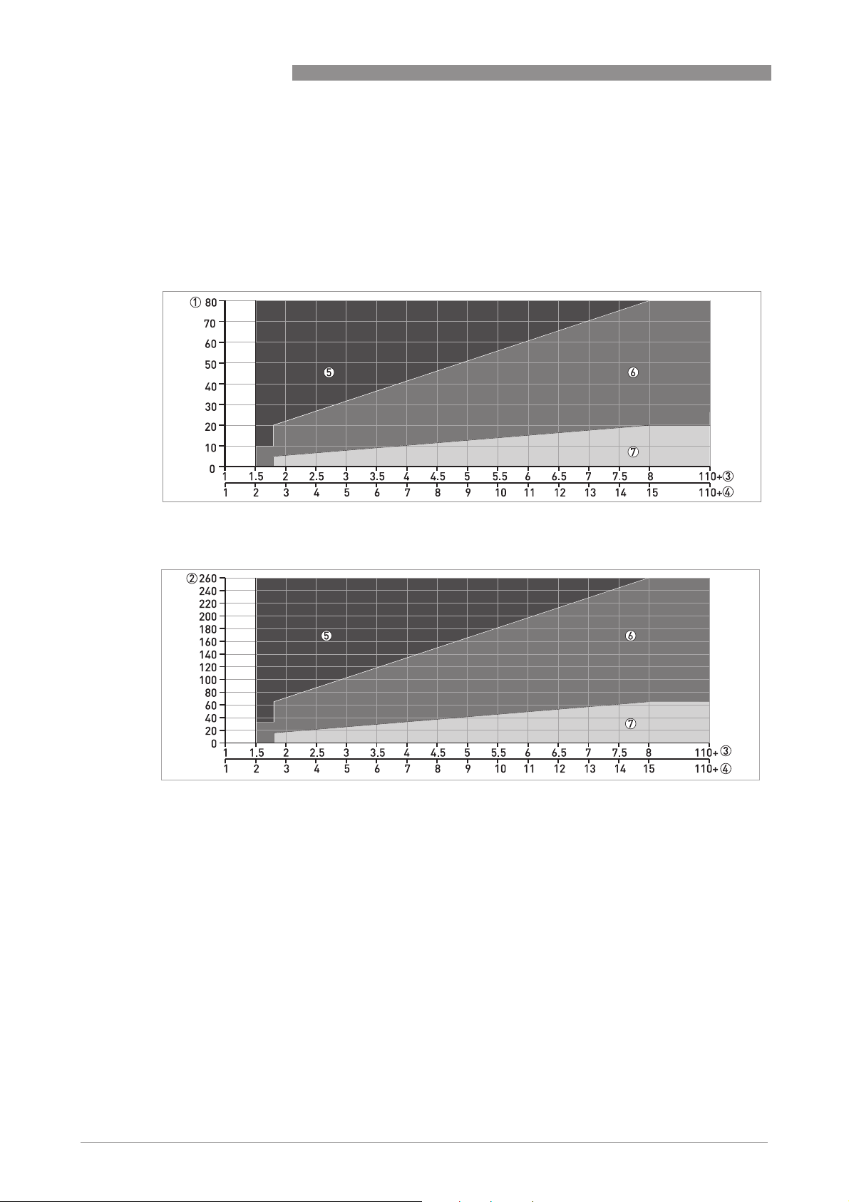
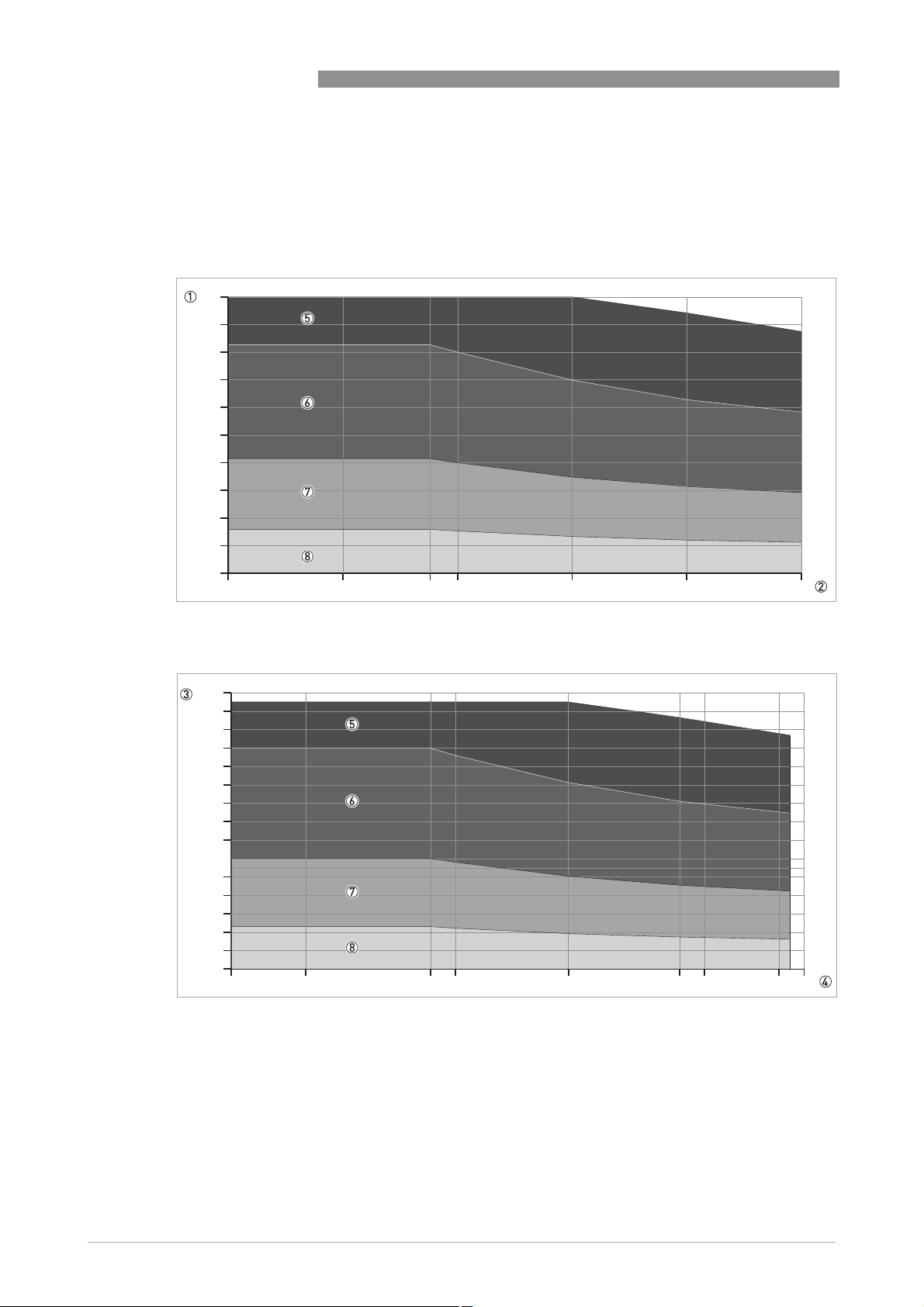
2.2 Antenna selection
The graphs below show which antenna to select for the application based on:
• D, the measuring range,
, is the dielectric constant of the product being measured
• ε
r
OPTIWAVE 7300 C
Figure 2-1: Selection of antenna for liquid applications (graph of distance in m against εr)
Figure 2-2: Selection of antenna for liquid applications (graph of distance in ft against ε
1 Distance, D [m]
2 Distance, D [ft]
3 Dielectric constant (ε
4 Dielectric constant (ε
5 DN80, DN100, DN150 or DN200 Horn antenna with a still well, or DN150 or DN200 Horn antenna without a still well
6 DN80, DN100, DN150 or DN200 Horn antenna with or without a still well, or DN80 or DN150 Drop antenna without a
still well
7 DN40, DN50, DN80, DN100, DN150 or DN200 Horn antenna with or without a still well, DN80 or DN150 Drop antenna
without a still well or Hygienic antenna
) range for storage/still well applications
r
) range for process/agitator applications
r
)
r
14
www.krohne.com 03/2015 - 4000112308 - TD OPTIWAVE 7300 R13 en
Page 15
OPTIWAVE 7300 C
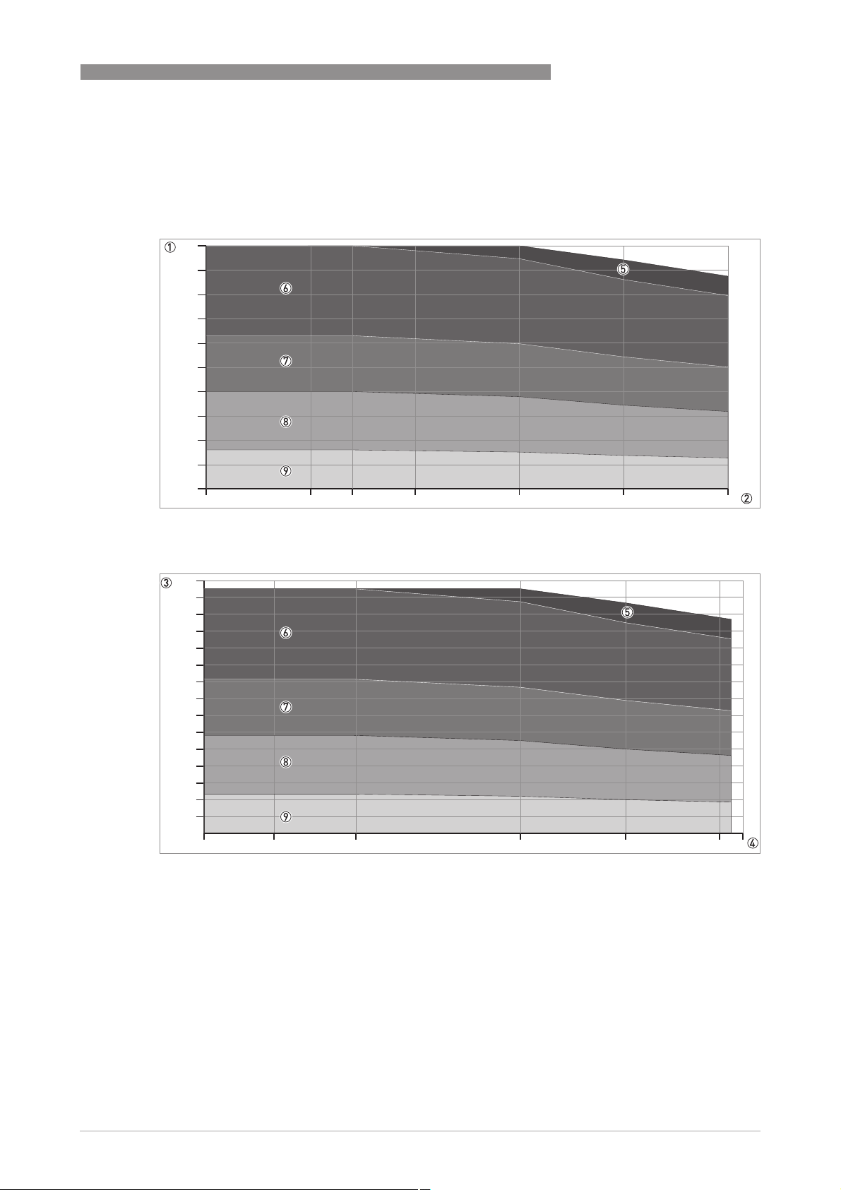
2.3 Guidelines for maximum operating pressure
Make sure that the devices are used within their operating limits.
100
90
80
70
60
50
40
30
20
10
TECHNICAL DATA
2
0
-50 0 50
Figure 2-3: Pressure / temperature de-rating (EN 1092-1), flange and threaded connection, in °C and barg
1500
1400
1300
1200
1100
1000
900
800
700
600
500
400
300
200
100
0
-60 0 68
Figure 2-4: Pressure / temperature de-rating (EN 1092-1), flange and threaded connections, in °F and psig
1 p [barg]
2 T [°C]
3 p [psig]
4 T [°F]
5 Threaded connection, G (ISO 228-1)
6 Flange connection, PN100
7 Flange connection, PN63
8 Flange connection, PN40
9 Flange connection, PN16
20
100 150 200
210
300
380 400
www.krohne.com03/2015 - 4000112308 - TD OPTIWAVE 7300 R13 en
15
Page 16
2
TECHNICAL DATA
CRN certification
CRN certification
CRN certificationCRN certification
There is a CRN certification option for devices with process connections that agree with ASME
standards. This certification is necessary for all devices that are installed on a pressure vessel
and used in Canada.
100
90
80
70
60
50
40
30
20
OPTIWAVE 7300 C
10
0
-50 0 5038 100 150 200
Figure 2-5: Pressure / temperature de-rating (ASME B16.5), flange and threaded connections, in °C and barg
1500
1400
1300
1200
1100
1000
900
800
700
600
500
400
300
200
100
0
-60 0 100 120 210 300 320 380 400
16
Figure 2-6: Pressure / temperature de-rating (ASME B16.5), flange and threaded connections, in °F and psig
1 p [barg]
2 T [°C]
3 p [psig]
4 T [°F]
5 Flange connection, Class 900 and Class 1500. Threaded connection, NPT (ASME B1.20.1).
6 Flange connection, Class 600
7 Flange connection, Class 300
8 Flange connection, Class 150
www.krohne.com 03/2015 - 4000112308 - TD OPTIWAVE 7300 R13 en
Page 17

OPTIWAVE 7300 C
2.4 Dimensions and weights
Housing
Figure 2-7: Housing dimensions
1 Housing front view
2 Housing side view
Dimensions and weights in mm and kg
TECHNICAL DATA
2
Dimensions [mm] Weights [kg]
a b c d e f g
Housing 180 122 158.5 182
1 If fitted with standard cable glands
Dimensions and weights in inches and lb
Dimensions [inches] Weights [lb]
a b c d e f g
Housing 7.1 4.8 6.2 7.2
1 If fitted with standard cable glands
•
Cable glands are delivered on demand with non-Ex, Ex i- and Ex d-approved devices.
•
The diameter of the outer sheath of the cable must be 7…12 mm or 0.28…0.47¨.
•
Cable glands for FM- or CSA-approved devices must be supplied by the customer.
•
A weather protection cover is available on request with all devices.
1
1
167 277 155 3.3
6.5 10.9 6.1 7.3
www.krohne.com03/2015 - 4000112308 - TD OPTIWAVE 7300 R13 en
17
Page 18

2
TECHNICAL DATA
Weather protection
Figure 2-8: Dimensions of the weather protection option
1 Weather protection, back view
2 Weather protection, left side view
Dimensions and weights in mm and kg
a b c d
OPTIWAVE 7300 C
Dimensions [mm] Weights [kg]
Weather
protection
1 Radius
208 231.5 268
Dimensions and weights in inches and lb
a b c d
Weather
protection
1 Radius
8.2 9.1 10.6
1
66 2.9
Dimensions [inches] Weights [lb]
1
2.6 6.4
18
www.krohne.com 03/2015 - 4000112308 - TD OPTIWAVE 7300 R13 en
Page 19

OPTIWAVE 7300 C
DN40/1.5¨ horn antenna versions
Figure 2-9: DN40 or 1.5¨ horn antenna versions
1 DN40/1.5¨ horn antenna with G 1½ or 1½ NPT thread connection
2 DN40/1.5¨ horn antenna with flange connection
Dimensions and weights in mm and kg
TECHNICAL DATA
2
Dimensions [mm] Weights [kg]
a b c d e f h Øi
Thread
connection
Flange
connection
1 If fitted with standard cable glands
2 Additional antenna extensions of Ø39 × length 105 mm are available
3 With ¼ NPTF purge connection option: add 17 mm to this dimension. With distance piece option: add 71 mm to this dimension.
194
194
1
1
170 201 233 359 32 126
170 201 246
3
342
3
45
3
96
2
2
39 5.1
39 6.6...14.1
Dimensions and weights in inches and lb
Dimensions [inches] Weights [lb]
a b c d e f h Øi
Thread
connection
Flange
connection
1 If fitted with standard cable glands
2 Additional antenna extensions of Ø1.5 × length 4.1¨ are available
3 With ¼ NPTF purge connection option: add 0.7¨ to this dimension. With distance piece option: add 2.8¨ to this dimension.
7.6
7.6
1
1
6.7 7.9 9.2 14.1 1.3 4.9
6.7 7.9 9.7
3
13.5
3
1.8
3
3.8
2
2
1.5 11.2
1.5 14.4...31.1
www.krohne.com03/2015 - 4000112308 - TD OPTIWAVE 7300 R13 en
19
Page 20

2
TECHNICAL DATA
DN50/2¨ horn antenna versions
Figure 2-10: DN50/2¨ horn antenna versions
1 DN50/2¨ horn antenna with G 1½ or 1½ NPT thread connection
2 DN50/2¨ horn antenna with flange connection
Dimensions and weights in mm and kg
OPTIWAVE 7300 C
Dimensions [mm] Weight [kg]
a b c d e f h Øi
Thread
connection
Flange
connection
1 If fitted with standard cable glands
2 Additional antenna extensions of Ø39 × length 105 mm are available
3 With ¼ NPTF purge connection option: add 17 mm to this dimension. With distance piece option: add 71 mm to this dimension.
182
182
1
1
167 201 234 370 32 136
167 201 246
3
353
3
45
3
107
2
2
43 5.3
43 6.8...14.3
Dimensions and weights in inches and lb
Dimensions [inches] Weights [lb]
a b c d e f h Øi
Thread
connection
Flange
connection
1 If fitted with standard cable glands
2 Additional antenna extensions of Ø1.5 × length 4.1¨ are available
3 With ¼ NPTF purge connection option: add 0.7¨ to this dimension. With distance piece option: add 2.8¨ to this dimension.
7.2
7.2
1
1
6.5 7.9 9.2 14.5 1.3 5.3
6.5 7.9 9.7
3
13.9
3
1.8
3
4.2
2
2
1.7 11.6
1.7 14.8...31.5
20
www.krohne.com 03/2015 - 4000112308 - TD OPTIWAVE 7300 R13 en
Page 21

OPTIWAVE 7300 C
DN80/3¨ horn antenna versions
Figure 2-11: DN80/3¨ horn antenna versions
1 DN80/3¨ horn antenna with G 1½ or 1½ NPT thread connection
2 DN80/3¨ horn antenna with flange connection
TECHNICAL DATA
2
Dimensions and weights in mm and kg
Dimensions [mm] Weights [kg]
a b c d e f h Øi
Thread
connection
Flange
connection
1 If fitted with standard cable glands
2 Additional antenna extensions of Ø39 × length 105 mm are available
3 With ¼ NPTF purge connection option: add 17 mm to this dimension. With distance piece option: add 71 mm to this dimension.
182
182
1
1
167 201 233 479 32 246
167 201 246
3
463
3
45
3
217
2
2
75 6.8
75 11.1...18.9
Dimensions and weights in inches and lb
Dimensions [inches] Weights [lb]
a b c d e f h Øi
Thread
connection
Flange
connection
1 If fitted with standard cable glands
2 Additional antenna extensions of Ø1.5 × length 4.1¨ are available
3 With ¼ NPTF purge connection option: add 0.7¨ to this dimension. With distance piece option: add 2.8¨ to this dimension.
7.2
7.2
1
1
6.5 7.9 9.2 18.9 1.3 9.7
6.5 7.9 9.7
3
18.2
3
1.8
3
8.5
2
2
3 15
3 24.4...41.5
www.krohne.com03/2015 - 4000112308 - TD OPTIWAVE 7300 R13 en
21
Page 22

2
TECHNICAL DATA
DN100/4¨ horn antenna versions
Figure 2-12: DN100/4¨ horn antenna versions
1 DN100/4¨ horn antenna with G 1½ or 1½ NPT thread connection
2 DN100/4¨ horn antenna with flange connection
OPTIWAVE 7300 C
22
www.krohne.com 03/2015 - 4000112308 - TD OPTIWAVE 7300 R13 en
Page 23

OPTIWAVE 7300 C
Dimensions and weights in mm and kg
a b c d e f h Øi
TECHNICAL DATA
2
Dimensions [mm] Weights [kg]
Thread
182
1
167 201 233 548 32 315
2
95 7.2
connection
Flange
182
1
167 201 246
3
532
3
45
3
286
2
95 11.6...28.2
connection
1 If fitted with standard cable glands
2 Additional antenna extensions of Ø39 × length 105 mm are available
3 With ¼ NPTF purge connection option: add 17 mm to this dimension. With distance piece option: add 71 mm to this dimension.
Dimensions and weights in inches and lb
Dimensions [inches] Weights [lb]
a b c d e f h Øi
Thread
connection
Flange
connection
1 If fitted with standard cable glands
2 Additional antenna extensions of Ø1.5 × length 4.1¨ are available
3 With ¼ NPTF purge connection option: add 0.7¨ to this dimension. With distance piece option: add 2.8¨ to this dimension.
7.2
7.2
1
1
6.5 7.9 9.2 21.6 1.3 12.4
6.5 7.9 9.7
3
20.9
3
1.8
3
11.3
2
2
3.7 15.8
3.7 25.6...62.2
www.krohne.com03/2015 - 4000112308 - TD OPTIWAVE 7300 R13 en
23
Page 24

2
TECHNICAL DATA
Sheet metal horn antenna versions
Figure 2-13: DN80/3¨, DN100/4¨, DN150/6¨ and DN200/8¨ sheet metal horn antenna versions
1 Sheet metal horn antenna (DN80/3¨, DN100/4¨, DN150/6¨ or DN200/8¨) with G 1½ or 1½ NPT thread connection
2 Sheet metal horn antenna (DN80/3¨, DN100/4¨, DN150/6¨ or DN200/8¨) with flange connection
3 Antenna purging system option (supplied with ¼NPTF connection)
OPTIWAVE 7300 C
24
www.krohne.com 03/2015 - 4000112308 - TD OPTIWAVE 7300 R13 en
Page 25

OPTIWAVE 7300 C
Dimensions and weights in mm and kg
a b c d e f h Øi
TECHNICAL DATA
2
Dimensions [mm] Weights
[kg]
Thread
connection
Flange
connection
1 If fitted with standard cable glands
2 Additional antenna extensions of Ø39 × length 105 mm are available
3 With ¼ NPTF purge connection option: add 17 mm to this dimension. With distance piece option: add 71 mm to this dimension.
DN80/3¨ 182
DN100/4¨ 182
DN150/6¨ 182
DN200/8¨ 182
DN80/3¨ 182
DN100/4¨ 182
DN150/6¨ 182
DN200/8¨ 182
1
1
1
1
1
1
1
1
167 201 234 483 33 249
167 201 234 552 33 318
167 201 234 720 33 486
167 201 234 878 33 644
167 201 246
167 201 246
167 201 246
167 201 246
3
3
3
3
467
536
704
862
3
3
3
3
45
45
45
45
3
3
3
3
221
290
458
616
2
2
2
2
2
2
2
2
75 4.9
95 5.1
144 5.5
190 6.1
75 9.2
95 9.5
144 14.4
190 15.0
Dimensions and weights in inches and lb
Dimensions [inches] Weights
a b c d e f h Øi
Thread
connection
DN80/3¨ 7.2
DN100/4¨ 7.2
DN150/6¨ 7.2
DN200/8¨ 7.2
1
1
1
1
6.5 7.9 9.2 19.0 1.3 9.8
6.5 7.9 9.2 21.7 1.3 12.5
6.5 7.9 9.2 28.3 1.3 19.1
6.5 7.9 9.2 34.6 1.3 25.4
2
2
2
2
3.0 10.8
3.7 11.1
5.7 12.2
7.5 13.4
[lb]
Flange
connection
1 If fitted with standard cable glands
2 Additional antenna extensions of Ø1.5 × length 4.1¨ are available
3 With ¼ NPTF purge connection option: add 0.7¨ to this dimension. With distance piece option: add 2.8¨ to this dimension.
DN80/3¨ 7.2
DN100/4¨ 7.2
DN150/6¨ 7.2
DN200/8¨ 7.2
1
1
1
1
6.5 7.9 9.7
6.5 7.9 9.7
6.5 7.9 9.7
6.5 7.9 9.7
3
3
3
3
18.4
21.1
27.7
33.9
3
3
3
3
1.8
1.8
1.8
1.8
3
3
3
3
8.7
11.4
18.0
24.3
2
2
2
2
3.0 20.2
3.7 20.8
5.7 31.6
7.5 32.9
www.krohne.com03/2015 - 4000112308 - TD OPTIWAVE 7300 R13 en
25
Page 26

2
TECHNICAL DATA
DN80/3¨ Drop antenna versions
Figure 2-14: DN80/3¨ Drop antenna versions
1 DN80/3¨ Drop antenna with G 1½ or 1½ NPT thread connection
2 DN80/3¨ Drop antenna with flange connection
3 DN80/3¨ Drop antenna, with PP or PTFE flange plate protection option
OPTIWAVE 7300 C
Dimensions and weights in mm and kg
Dimensions [mm] Weights [kg]
a b c d e f h Øi j
Thread connection 1821167 201 234 399 33 165
Flange connection 1821167 201 246 383 45 137
Flange connection with flange
plate protection option
1 If fitted with standard cable glands
2 Additional antenna extensions of Ø39 × length 105 mm are available. Do not attach more than 5 antenna extensions.
182
167 201 246 383 45 137 74 39 6.6…26.8
1
2
2
74 — 5.7…6.1
74 — 6.3…26
Dimensions and weights in inches and lb
Dimensions [inches] Weights [lb]
a b c d e f h Øi j
Thread connection 7.2
Flange connection 7.2
Flange connection with flange
plate protection option
1 If fitted with standard cable glands
2 Additional antenna extensions of Ø1.5 × length 4.1¨ available. Do not attach more than 5 antenna extensions.
7.2
1
6.5 7.9 9.2 15.7 1.3 6.5
1
6.5 7.9 9.7 15.1 1.8 5.4
1
6.5 7.9 9.7 15.1 1.8 5.4 2.9 1.5 13.9…59.1
2
2.9 — 12.6…13.4
2
2.9 — 13.9…57.3
26
www.krohne.com 03/2015 - 4000112308 - TD OPTIWAVE 7300 R13 en
Page 27

OPTIWAVE 7300 C
DN150/6¨ Drop antenna versions (PP material option only)
Figure 2-15: DN150/6¨ Drop antenna versions (PP material option only)
1 DN150/6¨ Drop antenna with flange connection
2 DN150/6¨ Drop antenna with thread connection
3 DN150/6¨ Drop antenna, with flange plate protection option
TECHNICAL DATA
2
Dimensions and weights in mm and kg
Dimensions [mm] Weights [kg]
a b c d e f h Øi j k
Thread connection 1821167 201 234 476 33 242
Flange connection 1821167 201 246 460 45 214
Flange connection with flange
plate protection option
1 If fitted with standard cable glands
2 Additional antenna extensions of Ø39 × length 105 mm are available. Do not attach more than 5 antenna extensions.
182
167 201 246 460 45 214 144 39 — 27.6
1
144 — — 7.4
2
144 — — 8…27.3
2
Dimensions and weights in inches and lb
Dimensions [inches] Weights [lb]
a b c d e f h Øi j k
Thread connection 7.216.5 7.9 9.2 18.7 1.3 9.5
Flange connection 7.216.5 7.9 9.7 18.1 1.8 8.4
Flange connection with flange
plate protection option
1 If fitted with standard cable glands
2 Additional antenna extensions of Ø1.5 × length 4.1¨ are available. Do not attach more than 5 antenna extensions.
7.2
6.5 7.9 9.7 18.1 1.8 8.4 5.7 1.5 — 60.8
1
5.7 — — 16.3
2
5.7 — — 17.6…60.2
2
www.krohne.com03/2015 - 4000112308 - TD OPTIWAVE 7300 R13 en
27
Page 28

2
TECHNICAL DATA
DN50/2¨ Hygienic antenna versions
Figure 2-16: DN50/2¨ Hygienic antenna versions
1 DN50/2¨ Hygienic antenna with Neumo BioControl® connection
2 DN50/2¨ Hygienic antenna with Tri-Clamp® connection
3 DN50/2¨ Hygienic antenna with SMS connection
4 DN50/2¨ Hygienic antenna with DIN 11851 connection
5 DN50/2¨ Hygienic antenna with VARIVENT® connection
Dimensions and weights in mm and kg
OPTIWAVE 7300 C
a b d h
Neumo BioControl® connection 182
Tri-Clamp® connection 182
SMS connection 182
DIN 11851 connection 182
VARIVENT® connection 182
1 If fitted with standard cable glands
Dimensions and weights in inches and lb
a b d h
Neumo BioControl® connection 7.2
Tri-Clamp® connection 7.2
SMS connection 7.2
DIN 11851 connection 7.2
VARIVENT® connection 7.2
1 If fitted with standard cable glands
1
1
1
1
1
1
1
1
1
1
Dimensions [mm] Weights [kg]
167 303 25 5.7
167 341 — 6.4
167 341 — 6.4
167 341 — 6.4
167 341 12 6.4
Dimensions [inches] Weights [lb]
6.5 11.9 25 12.7
6.5 13.4 — 14.1
6.5 13.4 — 14.1
6.5 13.4 — 14.1
6.5 13.4 0.5 14.1
28
www.krohne.com 03/2015 - 4000112308 - TD OPTIWAVE 7300 R13 en
Page 29

OPTIWAVE 7300 C
3.1 Intended use
This radar level transmitter measures distance, level, mass, volume and reflectivity of liquids,
pastes and slurries.
It can be installed on tanks, reactors and open channels.
3.2 Pre-installation requirements
Obey the precautions that follow to make sure that the device is correctly installed.
• Make sure that there is sufficient space on all sides.
• Protect the signal converter from direct sunlight. If necessary, install the weather protection
accessory.
• Do not subject the signal converter to heavy vibrations. The devices are tested for vibration
and agree with EN 50178 and IEC 60068-2-6.
INSTALLATION
3
www.krohne.com03/2015 - 4000112308 - TD OPTIWAVE 7300 R13 en
29
Page 30

3
INSTALLATION
3.3 How to prepare the tank before you install the device
To avoid measuring errors and device malfunction, obey these precautions.
3.3.1 Recommended mounting position
Follow these recommendations to make sure that the device measures correctly.
OPTIWAVE 7300 C
Figure 3-1: Recommended nozzle position for liquids, pastes and slurries
1 Nozzles for DN40 or DN50 Horn antennas, or DN50 Hygienic antenna
2 Nozzles for DN80, DN100, DN150 or DN200 Horn antennas and DN80 or DN150 Drop antennas
3 Tank height
4 Tank diameter
5 Minimum distance of nozzle from the tank wall : 1/7 × tank height
Maximum distance of nozzle from the tank wall : 1/3 × tank diameter
6 Minimum distance of nozzle from the tank wall : 1/10 × tank height
Maximum distance of nozzle from the tank wall : 1/3 × tank diameter
If possible, do not install a nozzle on the tank centerline.
Do not put the device near to the product inlet. If the product that enters the tank touches the
antenna, the device will measure incorrectly. If the product fills the tank directly below the
antenna, the device will also measure incorrectly.
30
www.krohne.com 03/2015 - 4000112308 - TD OPTIWAVE 7300 R13 en
Page 31

OPTIWAVE 7300 C
Figure 3-2: Product inlets
1 The device is in the correct position.
2 The device is too near to the product inlet.
INSTALLATION
3
Figure 3-3: More than 1 FMCW radar level meter can be operated in a tank
More than 1 FMCW radar level meter can be operated in a tank.
3.3.2 Theoretical data for hygienic applications
To make the cleaning of the antenna easier, attach the device to a short socket.
Figure 3-4: Requirements for hygienic applications
1 Maximum height of process connection: 50 mm / 2¨
www.krohne.com03/2015 - 4000112308 - TD OPTIWAVE 7300 R13 en
31
Page 32

3
INSTALLATION
3.4 Installation recommendations for liquids
3.4.1 General requirements
We recommend that you configure the device when the tank is empty.
OPTIWAVE 7300 C
Figure 3-5: General Installation recommendations
1 Do not tilt the device more than 2°
2 We recommend that you do an empty spectrum recording if there are too many obstacles in the radar beam (refer to
the handbook), or install a bypass chamber or stilling well.
3 2.5 mm / 0.1¨ max. for high-dielectric constant liquids
4 Curved and conical tank bottoms. Refer to the handbook for fine adjustment of the device.
5 Beam radius (DN40 horn antenna): increments of 180 mm/m or 2.15¨/ft (10°)
Beam radius (DN50 horn antenna or DN50 Hygienic antenna): increments of 130 mm/m or 1.55¨/ft (7.5°)
Beam radius (DN80 horn antenna): increments of 90 mm/m or 1.1¨/ft (5°)
Beam radius (DN100 horn antenna or DN80 Drop antenna): increments of 70 mm/m or 0.83¨/ft (4°)
Beam radius (DN150 horn antenna): increments of 52.5 mm/m or 0.63¨/ft (3°)
Beam radius (DN150 Drop antenna or DN200 horn antenna): increments of 35 mm/m or 0.42¨/ft (2°)
32
www.krohne.com 03/2015 - 4000112308 - TD OPTIWAVE 7300 R13 en
Page 33

OPTIWAVE 7300 C
3.4.2 Standpipes (stilling wells and bypass chambers)
Use a standpipe if:
• There is highly conductive foam in the tank.
• The liquid is very turbulent or agitated.
• There are too many other objects in the tank.
• The device is measuring a liquid (petro-chemicals) in a tank with a floating roof.
• The device is installed in a horizontal cylindrical tank (refer to the end of this section)
INSTALLATION
3
Figure 3-6: Installation recommendations for standpipes (stilling wells and bypass chambers)
1 A stilling well solution
2 A bypass chamber solution
3 Air circulation hole
4 Level of the liquid
•
The standpipe must be electrically conductive.
•
The inside diameter of the standpipe must not be more than 5 mm / 0.2¨ over the diameter of
the antenna (for a high-dielectric constant liquid).
•
The standpipe must be straight. There must be no sudden changes in internal diameter
¨
greater than 1 mm / 0.04
•
The standpipe must be vertical.
•
Recommended surface roughness: <±0.1 mm / 0.004¨.
•
Stilling well only: The bottom of the stilling well must be open.
•
Make sure that there are no deposits at the bottom of the standpipe.
•
Make sure that there is liquid in the standpipe.
.
www.krohne.com03/2015 - 4000112308 - TD OPTIWAVE 7300 R13 en
33
Page 34

3
INSTALLATION
Stilling wells: floating roofs
If the device must be installed on a tank with a floating roof, install it in a stilling well.
OPTIWAVE 7300 C
Figure 3-7: Floating roofs
1 Sediment
2 Support fixtures
3 Stilling well
4 Floating roof
5 Product
6 Tank
34
www.krohne.com 03/2015 - 4000112308 - TD OPTIWAVE 7300 R13 en
Page 35

OPTIWAVE 7300 C
Stilling wells: horizontal cylindrical tanks
We recommend that you install the device in a stilling well if the device:
• is for a horizontal cylindrical tank,
• is in a metallic tank,
• measures a product with a high dielectric constant and
• is on the centerline of the tank.
INSTALLATION
3
Figure 3-8: Horizontal cylindrical tanks
1 The device is installed without a stilling well. There are multiple reflections. Refer to the CAUTION! that follows.
2 The device is installed in a stilling well and measures correctly.
If the device is installed in horizontal cylindrical tank that contains a high dielectric constant
liquid without a stilling well, do not put it on the tank centerline. This will cause multiple
reflections and the device will not measure accurately. Use the Multiple Reflections
Supervisor > Advanced Setup > Installation Setup
Supervisor > Advanced Setup > Installation Setup to keep the effects of multiple reflections to a
Supervisor > Advanced Setup > Installation SetupSupervisor > Advanced Setup > Installation Setup
Multiple Reflections function in
Multiple ReflectionsMultiple Reflections
minimum. For more data, refer to "Function description" in the handbook.
www.krohne.com03/2015 - 4000112308 - TD OPTIWAVE 7300 R13 en
35
Page 36

3
INSTALLATION
Bypass chambers
Installation next to tanks containing one liquid and foam
• The top process connection of the bypass chamber must be above the maximum level of
liquid.
• The bottom process connection of the bypass chamber must be below the lowest measured
level of liquid.
Installation next to tanks containing more than one liquid
• The top process connection of the bypass chamber must be above the maximum level of
liquid.
• The bottom process connection of the bypass chamber must be below the lowest measured
level of liquid.
• Additional process connections are necessary for the liquids to circulate freely along the
length of the bypass chamber.
OPTIWAVE 7300 C
36
Figure 3-9: Installation recommendations for bypass chambers that contain more than one liquid
1 Bypass chamber
2 Additional process connection
www.krohne.com 03/2015 - 4000112308 - TD OPTIWAVE 7300 R13 en
Page 37

OPTIWAVE 7300 C
3.5 How to install the device on the tank
3.5.1 How to install a device with a flange connection
Equipment needed:
• Device
• Gasket (not supplied)
• Nuts and bolts (not supplied)
• Wrench (not supplied)
Requirements for flange connections
INSTALLATION
3
Figure 3-10: Flange connection
For more data, refer to the handbook.
3.5.2 How to install a device with a threaded connection
Equipment needed:
• Device
• Gasket for G 1½ connection (not supplied)
• 50 mm / 2¨ wrench (not supplied)
Requirements for threaded connections
Figure 3-11: Threaded connection
For more data, refer to the handbook.
www.krohne.com03/2015 - 4000112308 - TD OPTIWAVE 7300 R13 en
37
Page 38

3
INSTALLATION
3.5.3 How to install a device with a hygienic connection
To make the cleaning of the antenna easier, attach the device to a short socket.
BioControl®
Equipment needed:
• Device with BioControl® adaptor
• Flange bolts
• Wrench (not supplied)
OPTIWAVE 7300 C
Figure 3-12: BioControl® connection
1 BioControl
2 Flange bolts
®
connection on the tank
Tri-Clamp®
Equipment needed:
• Device with Tri-Clamp® adaptor
• Gasket (not supplied)
• Band clamp (not supplied)
38
Figure 3-13: Tri-Clamp® connection
1 Tank socket
2 Band clamp
www.krohne.com 03/2015 - 4000112308 - TD OPTIWAVE 7300 R13 en
Page 39

OPTIWAVE 7300 C
DIN 11851
Equipment needed:
• Device with a DIN 11851 adaptor
• Gasket (not supplied)
• DIN 11851 nut
INSTALLATION
3
Figure 3-14: DIN 11851 connection
1 Tank socket
2 Nut for DIN 11851 connection
SMS
Equipment needed:
• Device with a SMS adaptor
• Gasket (not supplied)
• SMS nut
Figure 3-15: SMS connection
1 Tank socket
2 Nut for SMS connection
www.krohne.com03/2015 - 4000112308 - TD OPTIWAVE 7300 R13 en
39
Page 40

3
INSTALLATION
VARIVENT®
Equipment needed:
• Device with a VARIVENT® adaptor
• Clamp (not supplied)
Figure 3-16: VARIVENT® connection
1 Tank socket (VARIVENT® Access Unit – not supplied)
OPTIWAVE 7300 C
40
www.krohne.com 03/2015 - 4000112308 - TD OPTIWAVE 7300 R13 en
Page 41

OPTIWAVE 7300 C
4.1 Safety instructions
All work on the electrical connections may only be carried out with the power disconnected. Take
note of the voltage data on the nameplate!
Observe the national regulations for electrical installations!
For devices used in hazardous areas, additional safety notes apply; please refer to the Ex
documentation.
Observe without fail the local occupational health and safety regulations. Any work done on the
electrical components of the measuring device may only be carried out by properly trained
specialists.
Look at the device nameplate to ensure that the device is delivered according to your order.
Check for the correct supply voltage printed on the nameplate.
ELECTRICAL CONNECTIONS
4
4.2 Electrical installation: outputs 1 and 2
Figure 4-1: Electrical installation
1 Terminal compartment cover
2 Output 1: current output -
3 Output 1: current output +
4 Grounding terminal in the housing
5 Output 2: current output - (option)
6 Output 2: current output + (option)
7 Grounding terminal between the process connection and the converter
Output 1 energizes the device and is used for HART® communication. If the device has the
second current output option, use a separate power supply to energize output 2.
www.krohne.com03/2015 - 4000112308 - TD OPTIWAVE 7300 R13 en
41
Page 42

4
ELECTRICAL CONNECTIONS
4.2.1 Non-Ex devices
Figure 4-2: Electrical connections for non-Ex devices (standard software)
1 Power supply
2 Resistor for HART® communication
3 Output 1: 14...30 VDC for an output of 22 mA at the terminal
4 Output 2: 10...30 VDC for an output of 22 mA at the terminal
OPTIWAVE 7300 C
Figure 4-3: Electrical connections for non-Ex devices (fast motion software option)
1 Power supply
2 Resistor for HART® communication
3 Output 1: 14...30 VDC for a constant output of 16 mA at the terminal
4 Output 2: 10...30 VDC for an output of 22 mA at the terminal
4.2.2 Devices for hazardous locations
For electrical data for device operation in hazardous locations, refer to the related certificates of
compliance and supplementary instructions (ATEX, IECEx, FM, CSA etc.). You can find this
documentation on the DVD-ROM delivered with the device or it can be downloaded free of charge
from the website (Download Center).
42
www.krohne.com 03/2015 - 4000112308 - TD OPTIWAVE 7300 R13 en
Page 43

OPTIWAVE 7300 C
4.3 Protection category
The device fulfils all requirements per protection category IP66 / IP67. It also fulfils all
requirements per NEMA type 4X (housing) and type 6P (antenna).
Make sure that the cable gland is watertight.
Figure 4-4: How to make the installation agree with protection category IP 67
• Make sure that the gaskets are not damaged.
• Make sure that the electrical cables are not damaged.
• Make sure that the electrical cables agree with the national electrical code.
• The cables are in a loop in front of the device 1 so water does not go into the housing.
• Tighten the cable feedthroughs 2.
• Close unused cable feedthroughs with dummy plugs 3.
ELECTRICAL CONNECTIONS
4
www.krohne.com03/2015 - 4000112308 - TD OPTIWAVE 7300 R13 en
43
Page 44

4
ELECTRICAL CONNECTIONS
4.4 Networks
4.4.1 General information
The device uses the HART® communication protocol. This protocol agrees with the HART®
Communication Foundation standard. The device can be connected point-to-point. It can also
operate in a multi-drop network of up to 15 devices.
The device output is factory-set to communicate point-to-point. To change the communication
mode from point-to-point
4.4.2 Point-to-point connection
point-to-point to multi-drop
point-to-pointpoint-to-point
multi-drop, refer to "Network configuration" in the handbook.
multi-dropmulti-drop
OPTIWAVE 7300 C
Figure 4-5: Point-to-point connection (non-Ex)
1 Address of the device (0 for point-to-point connection)
2 4...20 mA + HART®
3 Resistor for HART® communication
4 Power supply
5 HART® converter
6 HART® communication software
44
www.krohne.com 03/2015 - 4000112308 - TD OPTIWAVE 7300 R13 en
Page 45

OPTIWAVE 7300 C
4.4.3 Multi-drop networks
ELECTRICAL CONNECTIONS
4
Figure 4-6: Multi-drop network (non-Ex)
1 Address of the device (n+1 for multidrop networks)
2 Address of the device (1 for multidrop networks)
3 4mA + HART®
4 Resistor for HART® communication
5 Power supply
6 HART® converter
7 HART® communication software
www.krohne.com03/2015 - 4000112308 - TD OPTIWAVE 7300 R13 en
45
Page 46

5
ORDER INFORMATION
5.1 Order code
Make a selection from each column to get the full order code. The characters of the order code
highlighted in light grey describe the standard.
OPTIWAVE 7300 C
VF70 4 OPTIWAVE 7300 C 24 GHz Non-contact Radar (FMCW) level meter for liquids
VF70
VF70 4 Order code (complete this code on the pages that follow)
VF70VF70
OPTIWAVE 7300 C 24 GHz Non-contact Radar (FMCW) level meter for liquids
OPTIWAVE 7300 C 24 GHz Non-contact Radar (FMCW) level meter for liquidsOPTIWAVE 7300 C 24 GHz Non-contact Radar (FMCW) level meter for liquids
Approval
Approval
ApprovalApproval
0 Without
1 WHG (overfill protection)
2 ATEX Ex ia IIC T3...T6 + DIP
3 ATEX Ex d[ia] IIC T3...T6 + DIP
4 ATEX Ex ia IIC T3...T6 + DIP + WHG
5 ATEX Ex d[ia] IIC T3...T6 + DIP + WHG
6 FM IS CL I/II/III, DIV 1, GPS A-G; CL I, Zone 0, AEx ia IIC T3…T6
7 FM XP-IS/DIP CL I/II/III, DIV 1, GPS A-G; CL I, Zone 0, AEx d [ia] IIC T3…T6
A ATEX 3G Ex nA II T3...T6
B INMETRO Ex ia IIC T3…T6 + DIP
C INMETRO Ex d ia IIC T3…T6 + DIP
E NEPSI Ex ia IIC T3 ~ T6 + DIP
F NEPSI Ex d ia IIC T3 ~ T6 + DIP
H CSA IS CL I/II/III, DIV 1, GPS A-G; CL I, Zone 0, Ex ia IIC T3…T6
K CSA XP-IS/DIP CL I/II/III, DIV 2, GPS A-D, F, G; CL I, Zone 0, Ex d IIC T3…T6
M IECEx Ex ia IIC T2…T6 + DIP
N IECEx Ex d ia IIC T2…T6 + DIP
R KGS Ex ia IIC T3 – T6 + DIP
S KGS Ex d[ia] IIC T3 – T6 + DIP
Material of Process Connection / Antenna type and material (pressure)
Material of Process Connection / Antenna type and material (pressure)
Material of Process Connection / Antenna type and material (pressure)Material of Process Connection / Antenna type and material (pressure)
0 316L (1.4404) / Horn 316L (40 barg / 580 psig) – Drop PTFE (40 barg / 580 psig)
– Drop PP (16 barg / 232 psig) – Hygienic PEEK (10 barg / 145 psig)
1 Hastelloy® C-22® (2.4602) / Horn HC22 (40 barg / 580 psig)
2 316L (1.4404) / Horn 316 L (100 barg / 1450 psig)
3 Hastelloy® C-22® (2.4602) / Horn HC22 (100 barg / 1450 psig)
Order code (complete this code on the pages that follow)
Order code (complete this code on the pages that follow)Order code (complete this code on the pages that follow)
1
2
2
3
3
2
2
2
2
2
2
2
2
4
4
46
www.krohne.com 03/2015 - 4000112308 - TD OPTIWAVE 7300 R13 en
Page 47

OPTIWAVE 7300 C
Antenna type
Antenna type
Antenna typeAntenna type
ORDER INFORMATION
3 Horn DN80 (Ø75 mm / 2.95¨) – long
4 Horn DN40 (Ø39 mm / 1.54¨) – long
5 Horn DN50 (Ø43 mm / 1.69¨) – long
6 Horn DN80 (Ø75 mm / 2.95¨) – long – with purging system
7 Horn DN40 (Ø39 mm / 1.54¨) – long – with purging system
8 Horn DN50 (Ø43 mm / 1.69¨) – long – with purging system
F Horn DN100 (Ø95 mm / 3.74¨) – long
G Horn DN100 (Ø95 mm / 3.74¨) – long – with purging system
H PEEK Hygienic antenna (FDA conform)
L Horn for BM26 W (Ø65.4 mm / 2.58¨)
N Horn for BM 26 ADVANCED – with purging system
P Drop PTFE DN80 (Ø75 mm / 2.95¨) – long / -50…+150°C (-58…+302°F)
R Drop PP DN150 (Ø144 mm / 5.67¨) – long / -40...+100°C (-40…+212°F)
S Drop PP DN80 (Ø75 mm / 2.95¨) – long / -40…+100°C (-40…+212°F)
T Sheet metal horn DN 200 (Ø190 mm / 7.48¨) – long – with purging system
U Sheet metal Horn DN80 (Ø75 mm / 2.95¨) – long
V Sheet metal horn DN100 (Ø95 mm / 3.74¨) – long
W Sheet metal horn DN80 (Ø75 mm / 2.95¨) – long – with purging system
X Sheet metal horn DN100 (Ø95 mm / 3.74¨) – long – with purging system
Y Sheet metal horn DN150 (Ø144 mm / 5.67¨) – long – with purging system
Antenna extension
Antenna extension
Antenna extensionAntenna extension
0 Without
1 Extension 105 mm (4.13¨)
2 Extension 210 mm (8.27¨)
3 Extension 315 mm (12.40¨)
4 Extension 420 mm (16.54¨)
5 Extension 525 mm (20.67¨)
6 Extension 630 mm (24.80¨)
7 Extension 735 mm (28.94¨)
8 Extension 840 mm (33.07¨)
A Extension 945 mm (37.21¨)
B Extension 1050 mm (41.34¨)
Flange plate protection
Flange plate protection
Flange plate protectionFlange plate protection
5
5
5
5
5
P Flange plate protection (PP) DN80, DN100, 3¨, 4¨, 80A, 100A
R Flange plate protection (PP) DN150, 6¨, 8¨
6
S Flange plate protection (PTFE) DN80, DN100, 3¨, 4¨, 80A, 100A
T Flange plate protection (PTFE) DN150, 6¨, 8¨
VF70
VF70 4 Order code (complete this code on the pages that follow)
VF70VF70
Order code (complete this code on the pages that follow)
Order code (complete this code on the pages that follow)Order code (complete this code on the pages that follow)
6
5
6
6
www.krohne.com03/2015 - 4000112308 - TD OPTIWAVE 7300 R13 en
47
Page 48

5
ORDER INFORMATION
Feedthrough / Temperature / Sealing
Feedthrough / Temperature / Sealing
Feedthrough / Temperature / SealingFeedthrough / Temperature / Sealing
Non-Ex devices with a Drop antenna
X Standard / -40...+150°C (-40…+302°F) / FKM/FPM
Y Standard / -50…+150°C (-58…+302°F) / EPDM
Other devices
0 Standard / -40...+150°C (-40…+302°F) / FKM/FPM
1 Standard / -20...+150°C (-4…+302°F) / Kalrez 6375
2 Metaglas® / -30...+150°C (-22…302°F) / FKM/FPM
3 Metaglas® / -20...+150°C (-4…+302°F) / Kalrez 6375
4 Standard / -50...+150°C (-58…302°F) / EPDM
5 Metaglas® / -30...+150°C (-22…+302°F) / EPDM
B Standard / -20…+150°C (-4…+302°F) / EPDM – for hygienic connections
C Standard / -20…+150°C (-4…+302°F) / FKM/FPM – for hygienic connections
F Standard / -40...+200°C (-40…+392°F) / FKM/FPM with distance piece included
G Standard / -20...+200°C (-4…+392°F) / Kalrez 6375 with distance piece included
H Metaglas® / -30...+200°C (-22…+392°F) / FKM/FPM with distance piece included
K Metaglas® / -20...+200°C (-4…392°F) / Kalrez 6375 with distance piece included
Process connection EN
Process connection EN
Process connection ENProcess connection EN
0 Without
3 G1½A ISO 228
5 DN40 PN40 Type B1 EN 1092-1
6 DN50 PN40 Type B1 EN 1092-1
7 DN80 PN40 Type B1 EN 1092-1
8 DN100 PN16 Type B1 EN 1092-1
A DN100 PN40 Type B1 EN 1092-1
B DN150 PN16 Type B1 EN 1092-1
C DN150 PN40 Type B1 EN 1092-1
D DN50 PN63 Type B1 EN 1092-1
E DN80 PN63 Type B1 EN 1092-1
F DN100 PN63 Type B1 EN 1092-1
L DN40 PN63/PN100 Type B1 EN 1092-1
M DN50 PN100 Type B1 EN 1092-1
N DN80 PN100 Type B1 EN 1092-1
P DN100 PN100 Type B1 EN 1092-1
R DN150 PN63 Type B1 EN 1092-1
S DN150 PN100 Type B1 EN 1092-1
U DN 200 PN 16 Type B1 EN 1092-1
V DN 200 PN 40 Type B1 EN 1092-1
VF70
VF70 4 Order code (complete this code on the pages that follow)
VF70VF70
Order code (complete this code on the pages that follow)
Order code (complete this code on the pages that follow)Order code (complete this code on the pages that follow)
7
OPTIWAVE 7300 C
48
www.krohne.com 03/2015 - 4000112308 - TD OPTIWAVE 7300 R13 en
Page 49

OPTIWAVE 7300 C
Process connection ASME
Process connection ASME
Process connection ASMEProcess connection ASME
0 Without
3 1½ NPT
5 1½¨ 150 lb RF ASME B16.5
6 1½¨ 300 lb RF ASME B16.5
7 2¨ 150 lb RF ASME B16.5
8 2¨ 300 lb RF ASME B16.5
A 3¨ 150 lb RF ASME B16.5
B 3¨ 300 lb RF ASME B16.5
C 4¨ 150 lb RF ASME B16.5
D 4¨ 300 lb RF ASME B16.5
E 6¨ 150 lb RF ASME B16.5
F 8¨ 150 lb RF ASME B16.5
G 6¨ 300 lb RF ASME B16.5 (distance piece included)
L 2¨ 300 lb RF ASME B16.5 / BM 26 W
N 1½¨ 600 lb RF ASME B16.5
P 2¨ 600 lb RF ASME B16.5
R 3¨ 600 lb RF ASME B16.5 (distance piece included)
S 4¨ 600 lb RF ASME B16.5 (distance piece included)
U 1½¨ 900/1500 lb RJ ASME B16.5 (distance piece included)
V 2¨ 900/1500 lb RJ ASME B16.5 (distance piece included)
W 3¨ 900 lb RF ASME B16.5 (distance piece included)
X 4¨ 900 lb RF ASME B16.5 (distance piece included)
Process connection other
Process connection other
Process connection otherProcess connection other
0 Without
3 RJ (ASME B16.5) ring joint
5 10K 40A RF JIS B2220
6 10K 50A RF JIS B2220
7 10K 80A RF JIS B2220
8 10K 100A RF JIS B2220
B Tuchenhagen VARIVENT® DN50
C NEUMO BioControl® DN50
F Tri-Clamp® 2¨
L DIN 11851 DN50
P SMS 51
V Type C (EN 1092-1) tongue
W Type D (EN 1092-1) groove
X Type E (EN 1092-1) spigot
Y Type F (EN 1092-1) recess
VF70
VF70 4 Order code (complete this code on the pages that follow)
VF70VF70
Order code (complete this code on the pages that follow)
Order code (complete this code on the pages that follow)Order code (complete this code on the pages that follow)
ORDER INFORMATION
5
www.krohne.com03/2015 - 4000112308 - TD OPTIWAVE 7300 R13 en
49
Page 50

5
ORDER INFORMATION
Output
Output
OutputOutput
0 1 output: 4…20 mA (HART®)
2 2 outputs: 4...20 mA (HART®) + 4...20 mA
4 2 outputs: 16 mA (HART) + 4...20 mA fast motion software (5 measurements
per second)
Housing / Cable entry / Cable gland
Housing / Cable entry / Cable gland
Housing / Cable entry / Cable glandHousing / Cable entry / Cable gland
0 Aluminium / M20 × 1.5 (nickel-plated brass adaptor) / without
1 Aluminium / ½ NPT (nickel-plated brass adaptor) / without
2 Aluminium / G ½ (nickel-plated brass adaptor) / without
3 Aluminium / M20 × 1.5 (nickel-plated brass adaptor) /
plastic (non-Ex: black, Ex ia: blue)
4 Aluminium / M20 × 1.5 (nickel-plated brass adaptor) /
metal (only for Ex d)
A Stainless steel / M20 × 1.5 (stainless steel adaptor) / without
B Stainless steel / ½ NPT (stainless steel adaptor) / without
D Stainless steel / M20 × 1.5 (stainless steel adaptor) /
plastic M20 (non-Ex: black, Ex ia: blue)
E Stainless steel / M20 × 1.5 (stainless steel adaptor) /
metal M20 (only for Ex d)
Housing option
Housing option
Housing optionHousing option
0 Without
2 Stainless steel weather protection
HMI (display and keys)
HMI (display and keys)
HMI (display and keys)HMI (display and keys)
0 Without
1 English
2 German
3 French
4 Italian
5 Spanish
6 Portuguese
7 Japanese
8 Chinese (simplified)
A Russian
Version
Version
VersionVersion
0 KROHNE (RAL 9006 / RAL 5005)
5 KROHNE USA (FCC 2 GHz)
8 KROHNE USA (250 MHz)
A KMIC L (for liquid applications)
VF70
VF70 4 0 Order code (complete this code on the pages that follow)
VF70VF70
Order code (complete this code on the pages that follow)
Order code (complete this code on the pages that follow)Order code (complete this code on the pages that follow)
OPTIWAVE 7300 C
50
www.krohne.com 03/2015 - 4000112308 - TD OPTIWAVE 7300 R13 en
Page 51

OPTIWAVE 7300 C
0 Other approval
Other approval
Other approvalOther approval
0 Without
B EAC Russia
C EAC Belarus
K EAC Kazakhstan
0 Calibration certificate
VF70
VF70 4 0 0 Order code
VF70VF70
1 The WHG approval is available for devices with an antenna diameter equal to or larger than DN80 / 3¨
2 DIP= Dust Ignition Proof
3 DIP= Dust Ignition Proof. The WHG approval is available for devices with an antenna diameter equal to or larger than DN80 / 3¨.
4 On request
5 This option is not available for devices with a Drop antenna
6 This option is available if the flange has a flange face Type B1 or Raised Face (RF)
7 This option can be attached to a stainless steel flange with a low pressure rating. For more data, refer to the list of accessories in the
handbook.
ORDER INFORMATION
Calibration certificate
Calibration certificateCalibration certificate
0 Without
1 Calibration certificate 2 factory-default points
for an accuracy of ±3mm/ ±0.12¨
2 Calibration certificate 5 factory-default points
for an accuracy of ±3mm/ ±0.12¨ points
(minimum distance of first point: 300 mm /
11.81¨)
Construction
Construction
ConstructionConstruction
0 Without
3 NACE-Design (MR 0175 / MR 0103 /
ISO 15156)
Tag N
Tag N°
Tag NTag N
0 Without
2 Tag N° on stainless steel plate
(16 characters max.)
Order code
Order codeOrder code
5
www.krohne.com03/2015 - 4000112308 - TD OPTIWAVE 7300 R13 en
51
Page 52

K
K
K
KROHNE product overview
•
Electromagnetic flowmeters
•
Variable area flowmeters
•
Ultrasonic flowmeters
•
Mass flowmeters
•
Vortex flowmeters
•
Flow controllers
•
Level meters
•
Temperature assemblies
•
Pressure transmitters
•
Analysis products
•
Products and systems for the oil & gas industry
•
Measuring systems for the marine industry
© KROHNE 03/2015 - 4000112308 - TD OPTIWAVE 7300 R13 en - Subject to change without notice.
Head Office KROHNE Messtechnik GmbH
Ludwig-Krohne-Str. 5
47058 Duisburg (Germany)
Tel.:+49 203 301 0
Fax:+49 203 301 103 89
info@krohne.com
The current list of all KROHNE contacts and addresses can be found at:
www.krohne.com
 Loading...