

KROHNE OPTIFLEX 2200 C/F Quick Start Guide
Quick Start
Quick Start
OPTIFLEX 2200 C/F
OPTIFLEX 2200 C/F
OPTIFLEX 2200 C/FOPTIFLEX 2200 C/F
Guided Radar (TDR) Level Transmitter for storage and
process applications
Quick StartQuick Start
© KROHNE 12/2016 - 4000622105 - QS OPTIFLEX 2200 R05 en

CONTENTS
OPTIFLEX 2200 C/F
1 Safety instructions 4
2 Installation 5
2.1 Intended use ..................................................................................................................... 5
2.2 Scope of delivery............................................................................................................... 6
2.3 Visual Check ..................................................................................................................... 7
2.4 Storage ............................................................................................................................. 8
2.5 Transport .......................................................................................................................... 9
2.6 Pre-installation requirements ......................................................................................... 9
2.7 How to prepare the tank before you install the device.................................................. 10
2.7.1 Pressure and temperature ranges....................................................................................... 10
2.7.2 General information for nozzles........................................................................................... 13
2.7.3 Installation requirements for concrete roofs....................................................................... 15
2.8 Installation recommendations for liquids...................................................................... 16
2.8.1 General requirements .......................................................................................................... 16
2.8.2 Installation in standpipes (stilling wells and bypass chambers) ......................................... 17
2.9 Installation recommendations for solids....................................................................... 18
2.9.1 Nozzles on conical silos........................................................................................................ 18
2.9.2 Traction loads on the probe.................................................................................................. 19
2.10 How to install the device on the tank ........................................................................... 20
2.10.1 How to assemble the single rod probe (single-piece probe) ............................................. 20
2.10.2 How to assemble the single rod probe (segmented probe)............................................... 24
2.10.3 How to assemble the segmented coaxial probe ................................................................ 27
2.10.4 How to install a device with a flange connection................................................................ 30
2.10.5 How to install a device with a threaded connection........................................................... 31
2.10.6 How to install a device with a hygienic connection ............................................................ 32
2.10.7 How to install a cable probe in the tank ............................................................................. 34
2.10.8 How to turn or remove the signal converter ...................................................................... 35
2.10.9 Recommendations for pits and tanks made of non-conductive materials........................ 36
2.10.10 Wall support for the remote version ................................................................................ 37
2.10.11 How to attach the weather protection to the device......................................................... 37
2.10.12 How to open the weather protection ................................................................................ 40
2.11 Electromagnetic compatibility ..................................................................................... 41
3 Electrical connections 42
3.1 Electrical installation: 2-wire, loop-powered ................................................................ 42
3.1.1 Compact version ................................................................................................................... 42
3.1.2 Remote version ..................................................................................................................... 44
3.2 Non-Ex devices............................................................................................................... 45
3.3 Devices for hazardous locations .................................................................................... 45
3.4 Minimum power supply voltage ..................................................................................... 46
3.5 Protection category ........................................................................................................47
3.6 Networks ........................................................................................................................ 48
3.6.1 General information.............................................................................................................. 48
3.6.2 Point-to-point networks ....................................................................................................... 48
3.6.3 Multi-drop networks ............................................................................................................. 49
3.6.4 Fieldbus networks................................................................................................................. 50
2
www.krohne.com 12/2016 - 4000622105 - QS OPTIFLEX 2200 R05 en

OPTIFLEX 2200 C/F
CONTENTS
4 Operation 52
4.1 General notes ................................................................................................................. 52
4.2 Digital display screen .....................................................................................................52
4.2.1 Local display screen layout .................................................................................................. 52
4.2.2 Functions of keypad buttons................................................................................................. 52
4.3 Commissioning............................................................................................................... 53
4.4 Probe length calculation ................................................................................................ 55
4.5 Snapshot ......................................................................................................................... 57
5 Notes 59
www.krohne.com12/2016 - 4000622105 - QS OPTIFLEX 2200 R05 en
3
1
SAFETY INSTRUCTIONS
Warnings and symbols used
DANGER!
This information refers to the immediate danger when working with electricity.
DANGER!
These warnings must be observed without fail. Even partial disregard of this warning can lead to
serious health problems and even death. There is also the risk of seriously damaging the device
or parts of the operator's plant.
WARNING!
Disregarding this safety warning, even if only in part, poses the risk of serious health problems.
There is also the risk of damaging the device or parts of the operator's plant.
CAUTION!
Disregarding these instructions can result in damage to the device or to parts of the operator's
plant.
INFORMATION!
These instructions contain important information for the handling of the device.
OPTIFLEX 2200 C/F
HANDLING
• This symbol designates all instructions for actions to be carried out by the operator in the
specified sequence.
i RESULT
RESULT
RESULTRESULT
This symbol refers to all important consequences of the previous actions.
Safety instructions for the operator
CAUTION!
Installation, assembly, start-up and maintenance may only be performed by appropriately
trained personnel. The regional occupational health and safety directives must always be
observed.
LEGAL NOTICE!
The responsibility as to the suitability and intended use of this device rests solely with the user.
The supplier assumes no responsibility in the event of improper use by the customer. Improper
installation and operation may lead to loss of warranty. In addition, the "Terms and Conditions of
Sale" apply which form the basis of the purchase contract.
INFORMATION!
•
Further information can be found in the handbook and on the data sheet. These documents
can be downloaded from the website (Download Center).
•
If you need to return the device to the manufacturer or supplier, please fill out the device
return form and send it with the device. Unfortunately, the manufacturer cannot repair or
inspect the device without the completed form. The form can be found in the handbook or
downloaded from the website. Click on the "Service" tab on one of the web pages and read
the instructions.
4
www.krohne.com 12/2016 - 4000622105 - QS OPTIFLEX 2200 R05 en

OPTIFLEX 2200 C/F
2.1 Intended use
CAUTION!
Responsibility for the use of the measuring devices with regard to suitability, intended use and
corrosion resistance of the used materials against the measured fluid lies solely with the
operator.
INFORMATION!
The manufacturer is not liable for any damage resulting from improper use or use for other than
the intended purpose.
This TDR level transmitter measures distance, level, mass and volume of liquids, pastes,
slurries, granulates and powders.
It can be installed on tanks, silos and open pits.
INSTALLATION
2
www.krohne.com12/2016 - 4000622105 - QS OPTIFLEX 2200 R05 en
5
2
INSTALLATION
2.2 Scope of delivery
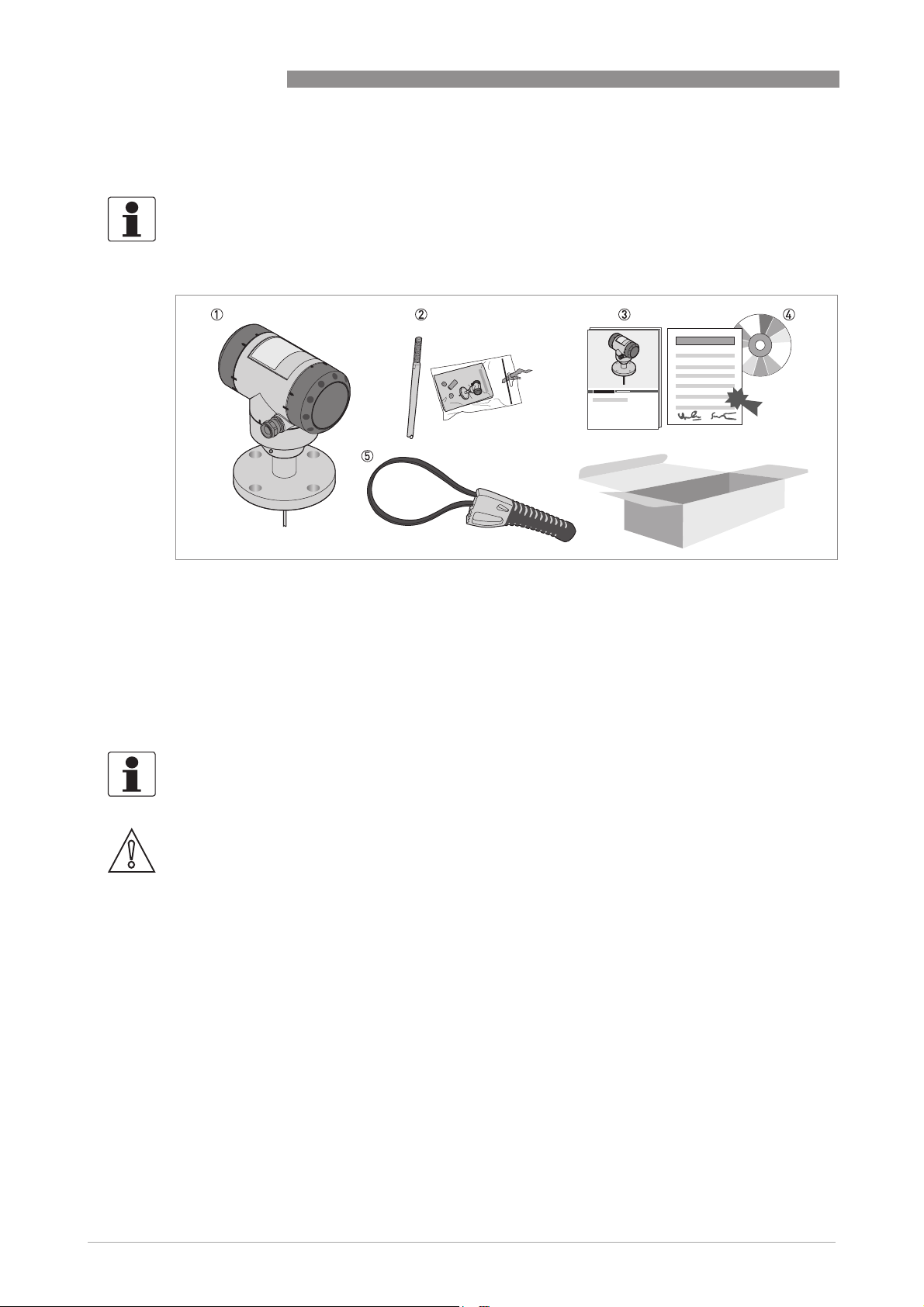
INFORMATION!
Do a check of the packing list to make sure that you have all the elements given in the order.
OPTIFLEX 2200 C/F
Figure 2-1: Scope of delivery
1 Signal converter and probe.
2 Probe segments. For the assembly procedure of the single rod probe, refer to the instructions that are supplied with
the device. If a single rod or coaxial probe is attached and you ordered the "segmented probe" option, only part of the
probe is attached to the device. For the assembly procedure of the segmented single rod probe, refer to the instructions that are supplied with the device. For the assembly procedure of the segmented coaxial probe, refer to the instructions that are supplied with the device.
3 Quick Start
4 DVD-ROM. This contains the Handbook, the Quick Start and the Technical Data Sheet.
5 Strap wrench
INFORMATION!
No training required!
CAUTION!
Make sure that the length of the probe is correct.
6
www.krohne.com 12/2016 - 4000622105 - QS OPTIFLEX 2200 R05 en
OPTIFLEX 2200 C/F
2.3 Visual Check
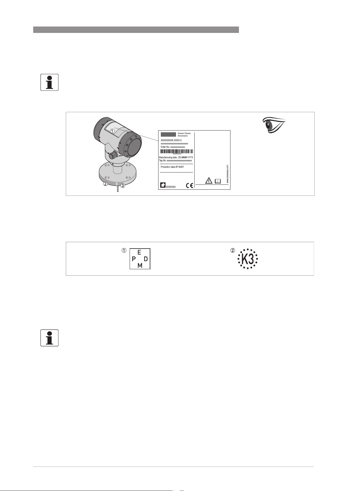
INFORMATION!
Inspect the packaging carefully for damages or signs of rough handling. Report damage to the
carrier and to the local office of the manufacturer.
INSTALLATION
2
Figure 2-2: Visual check
1 Device nameplate (for more data, refer to the handbook)
2 Process connection data (size and pressure rating, material reference and heat number)
3 Gasket material data – refer to the illustration that follows
Figure 2-3: Symbols for the supplied gasket material (on the side of the process connection)
1 EPDM
2 Kalrez® 6375
If the device is supplied with an FKM/FPM gasket, there is no symbol on the side of the process
connection.
INFORMATION!
Look at the device nameplate to ensure that the device is delivered according to your order.
Check for the correct supply voltage printed on the nameplate.
www.krohne.com12/2016 - 4000622105 - QS OPTIFLEX 2200 R05 en
7
2
INSTALLATION
2.4 Storage
WARNING!
Do not keep the device in a vertical position. This will damage the probe and the device will not
measure correctly.
OPTIFLEX 2200 C/F
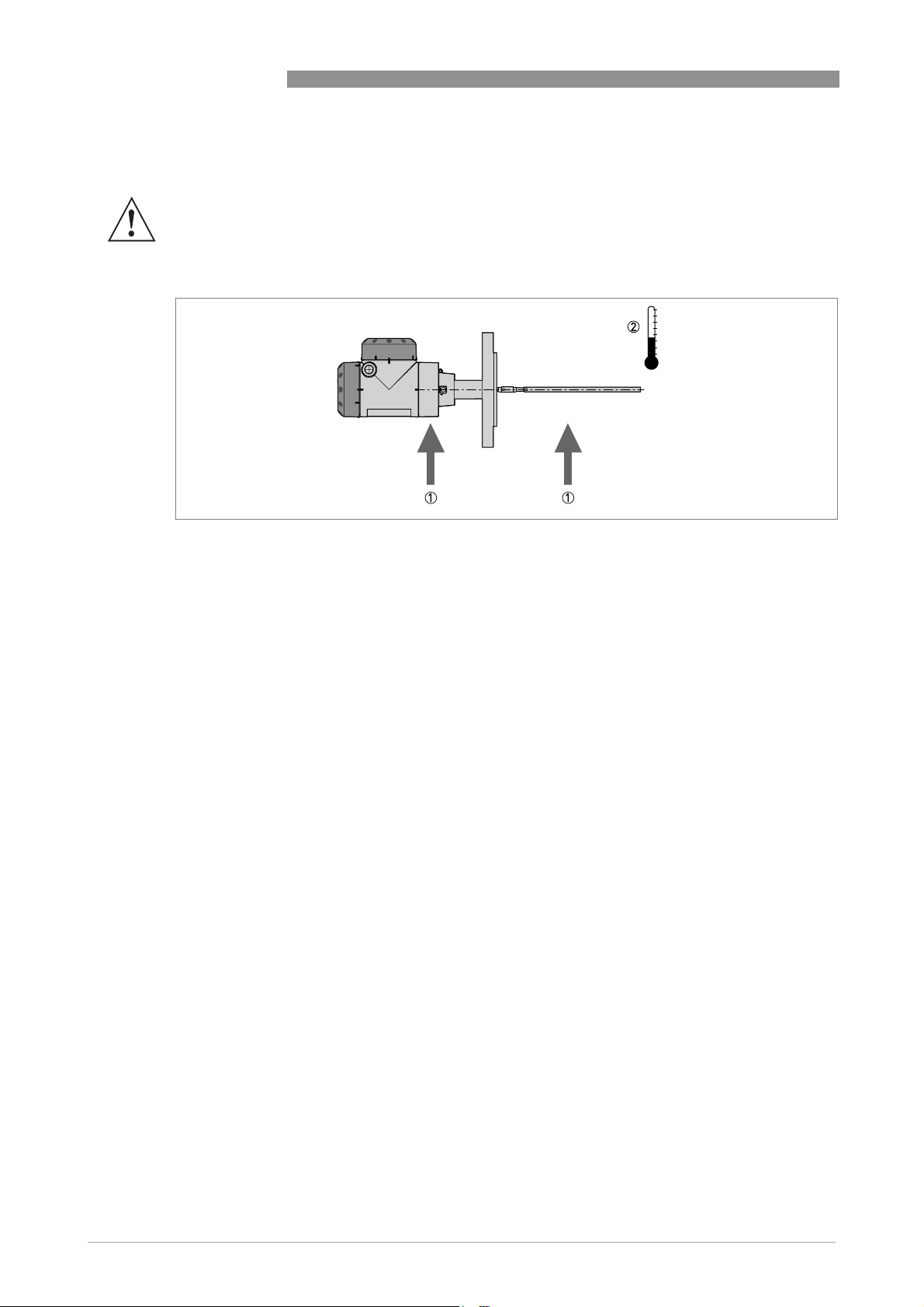
Figure 2-4: Storage conditions
1 Do not bend rod and coaxial probes – support here
2 Storage temperature range: -50…+85°C/ -60…+185°F (min. -40°C/ -40°F for devices with the integrated LCD display
option)
• Store the device in a dry and dust-free location.
• Store the device in its original packing.
8
www.krohne.com 12/2016 - 4000622105 - QS OPTIFLEX 2200 R05 en
OPTIFLEX 2200 C/F
2.5 Transport
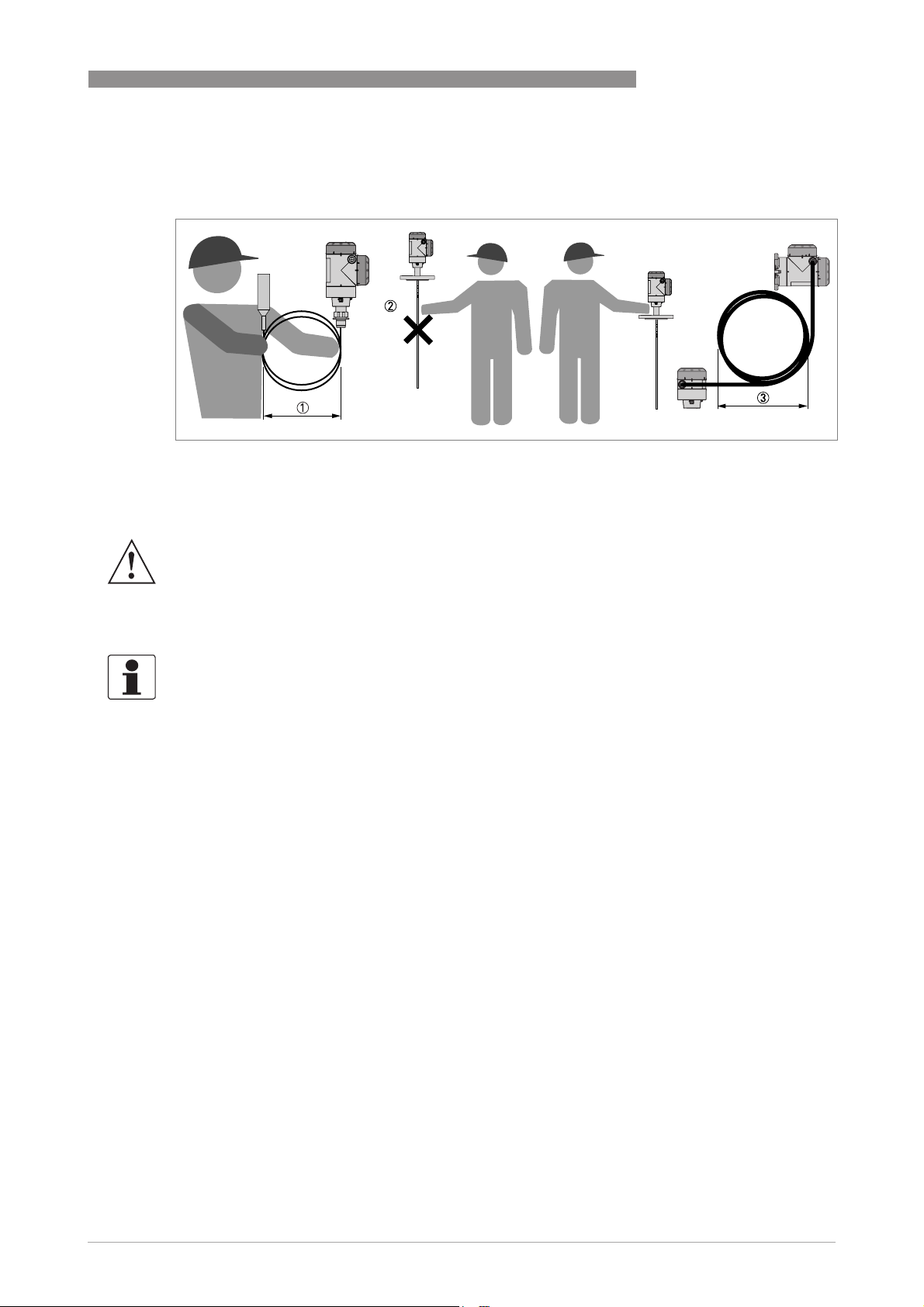
Figure 2-5: How to hold the device
1 Wind cable probes greater than 400 mm / 16¨ in diameter.
2 Do not hold the probe when you lift the device.
3 Do not wind the electrical cable less than 330 mm / 13¨ in diameter.
INSTALLATION
2
WARNING!
If you do not lift the device carefully, you can cause damage to the probe.
2.6 Pre-installation requirements
INFORMATION!
Obey the precautions that follow to make sure that the device is correctly installed.
• Make sure that there is sufficient space on all sides.
• Protect the signal converter from direct sunlight. If necessary, install the weather protection
accessory.
• Do not subject the signal converter to heavy vibrations.
www.krohne.com12/2016 - 4000622105 - QS OPTIFLEX 2200 R05 en
9
2
INSTALLATION
2.7 How to prepare the tank before you install the device
CAUTION!
To avoid measuring errors and device malfunction, obey these precautions.
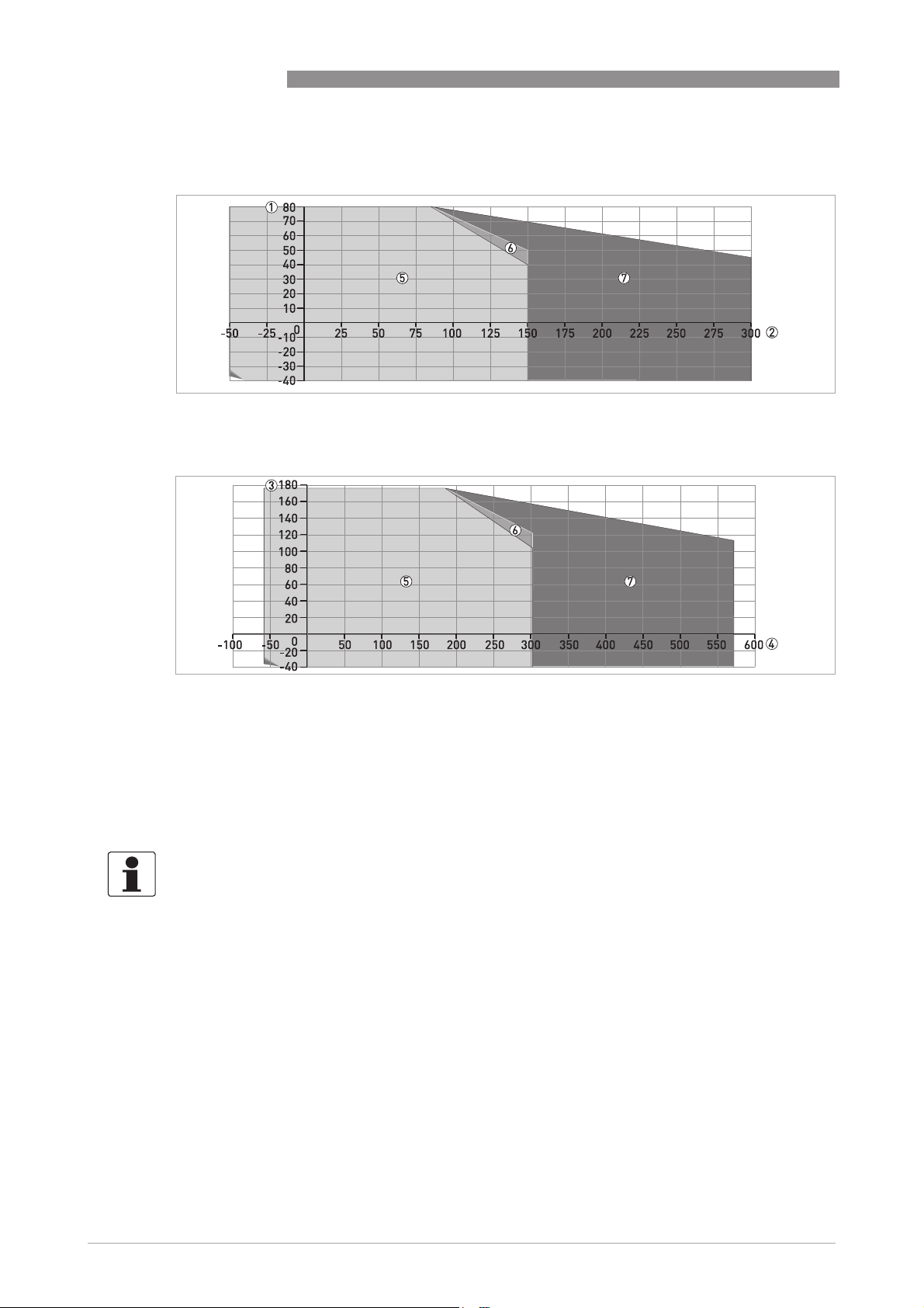
2.7.1 Pressure and temperature ranges
OPTIFLEX 2200 C/F
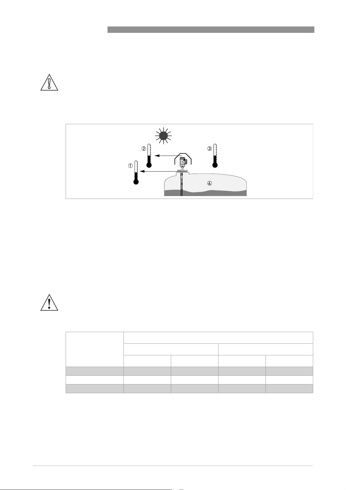
Figure 2-6: Pressure and temperature ranges
1 Temperature at the process connection
The temperature at the process connection must stay in the temperature range of the gasket material unless the device is a High-Temperature version. Refer to the table "Permitted temperature ranges for gaskets" that follows and
to "Technical data" in the handbook.
Devices with Hazardous Location approvals: see supplementary instructions
2 Ambient temperature for operation of the display
-20...+60°C / -4...+140°F
If the ambient temperature is not between these limits, the display screen switches off automatically
3 Ambient temperature
Non-Ex devices: min. (Compact) -36°C/ -33°F, min. (Remote) -37°C/ -34.6°F max. +80°C / +176°F
Devices with Hazardous Location approvals: see supplementary instructions
4 Process pressure
-1...40 barg / -14.5...580 psig
WARNING!
The process connection temperature range must agree with the temperature limits of the
gasket material.
Permitted temperature ranges for gaskets
Gasket material Permitted temperature ranges for gaskets
Standard version High-Temperature version
[°C] [°F] [°C] [°F]
FKM/FPM -40…+150 -40…+302 -40…+300 -40…+572
Kalrez® 6375 -20…+150 -4…+302 -20…+300 -4…+572
EPDM -50…+150 -58…+302 -50…+250 -58…+482
10
www.krohne.com 12/2016 - 4000622105 - QS OPTIFLEX 2200 R05 en
OPTIFLEX 2200 C/F
Compact version:
Ambient temperature / flange temperature, flange and threaded connection, in °C
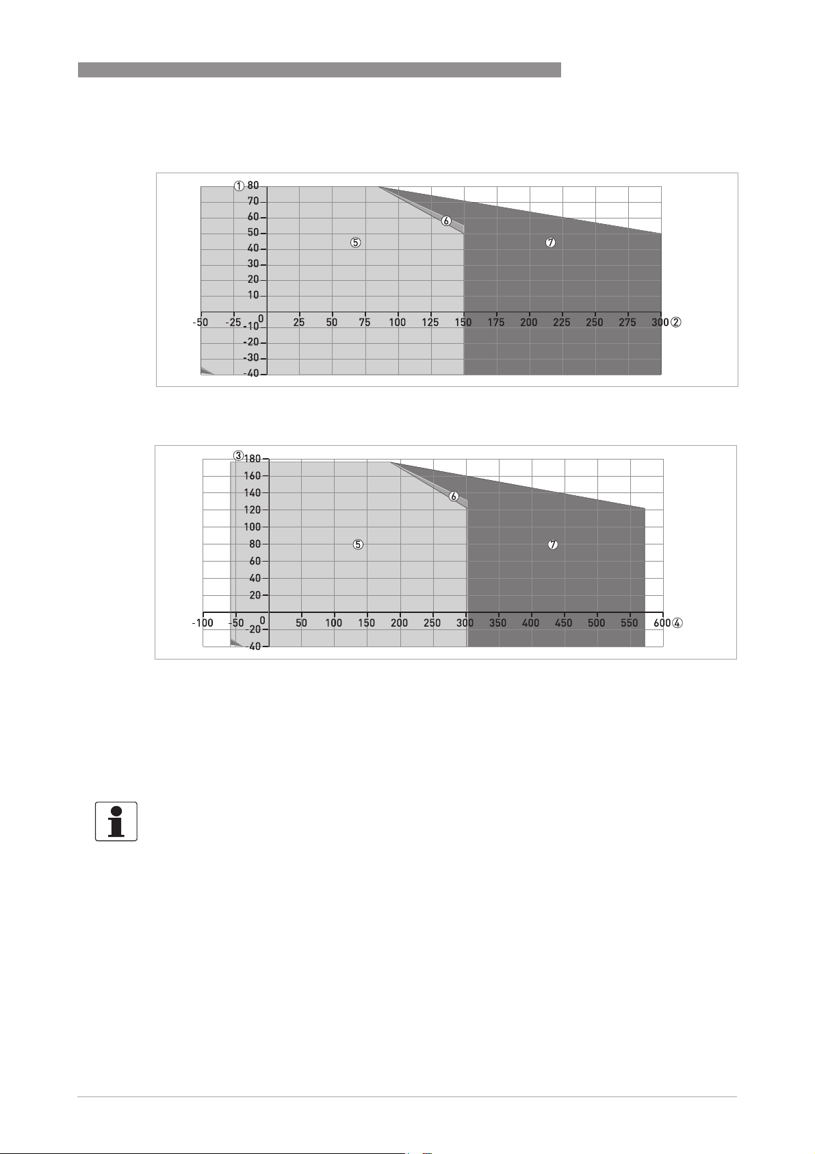
Figure 2-7: Compact version: Ambient temperature / flange temperature, flange and threaded connection, in °C
Ambient temperature / flange temperature, flange and threaded connection, in °F
INSTALLATION
2
Figure 2-8: Compact version: Ambient temperature / flange temperature, flange and threaded connection, in °F
1 Maximum ambient temperature, °C
2 Maximum flange temperature, °C
3 Maximum ambient temperature, °F
4 Maximum flange temperature, °F
5 All probes
6 All versions of the 2 mm / 0.08¨ single cable probe
7 High-Temperature (HT) version of the Ø2 mm / 0.08¨ single cable probe
INFORMATION!
°
When the process temperature is -50
C/ -58°F and the device has a EPDM gasket, there is a de-
rating for the ambient temperature:
Compact version
Compact version
Compact versionCompact version
= -36°C/ -32.8°F for the Ø2 mm / 0.08¨ single cable probe
T
a
T
= -39°C/ -38.2°F for the high-temperature (HT) version of the Ø2 mm / 0.08¨ single cable
a
probe
= -37°C/ -34.6°F for all other probes
T
a
Hygienic applications only:
Hygienic applications only: When the process temperature is -45
Hygienic applications only:Hygienic applications only:
EPDM gasket, there is a de-rating for the ambient temperature. T
°
C/ -49°F and the device has an
= -39°C / -38.2°F
a
www.krohne.com12/2016 - 4000622105 - QS OPTIFLEX 2200 R05 en
11
2
INSTALLATION
Remote version (probe housing):
Ambient temperature / flange temperature, flange and threaded connection, in °C
Figure 2-9: Remote version (probe housing): Ambient temperature / flange temperature, flange and threaded
connection, in °C
Ambient temperature / flange temperature, flange and threaded connection, in °F
OPTIFLEX 2200 C/F
Figure 2-10: Remote version (probe housing): Ambient temperature / flange temperature, flange and threaded
connection, in °F
1 Maximum ambient temperature, °C
2 Maximum flange temperature, °C
3 Maximum ambient temperature, °F
4 Maximum flange temperature, °F
5 All probes
6 All versions of the 2 mm / 0.08¨ single cable probe
7 High-Temperature (HT) version of the Ø2 mm / 0.08¨ single cable probe
INFORMATION!
°
When the process temperature is -50
C/ -58°F and the device has a EPDM gasket, there is a de-
rating for the ambient temperature:
Remote version (probe housing)
Remote version (probe housing)
Remote version (probe housing)Remote version (probe housing)
= -35°C/ -31°F for the Ø2 mm / 0.08¨ single cable probe
T
a
= -39°C/ -38.2°F for the high-temperature (HT) version of the Ø2 mm / 0.08¨ single cable
T
a
probe
T
= -36°C/ -32.8°F for all other probes
a
Hygienic applications only:
Hygienic applications only: When the process temperature is -45
Hygienic applications only:Hygienic applications only:
EPDM gasket, there is a de-rating for the ambient temperature. T
°
C/ -49°F and the device has an
= -39°C / -38.2°F
a
12
www.krohne.com 12/2016 - 4000622105 - QS OPTIFLEX 2200 R05 en
OPTIFLEX 2200 C/F
2.7.2 General information for nozzles
CAUTION!
Follow these recommendations to make sure that the device measures correctly. They have an
effect on the performance of the device.
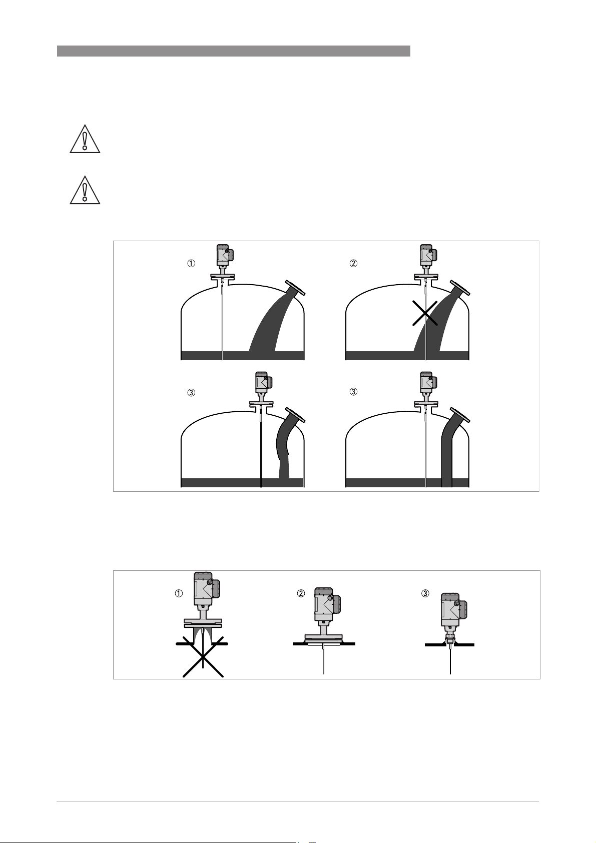
CAUTION!
Do not put the process connection near to the product inlet. If the product that enters the tank
touches the probe, the device will measure incorrectly.
INSTALLATION
2
Figure 2-11: Do not put the device near to a product inlet
1 The device is in the correct position.
2 The device is too near to the product inlet.
3 If it is not possible to put the device in the recommended position, install a deflector pipe.
Figure 2-12: How to prevent build-up of product around the process connection
1 If product particles are likely to collect in holes, a nozzle is not recommended.
2 Attach the flange directly to the tank.
3 Use a threaded connection to attach the device directly to the tank.
www.krohne.com12/2016 - 4000622105 - QS OPTIFLEX 2200 R05 en
13
2
INSTALLATION
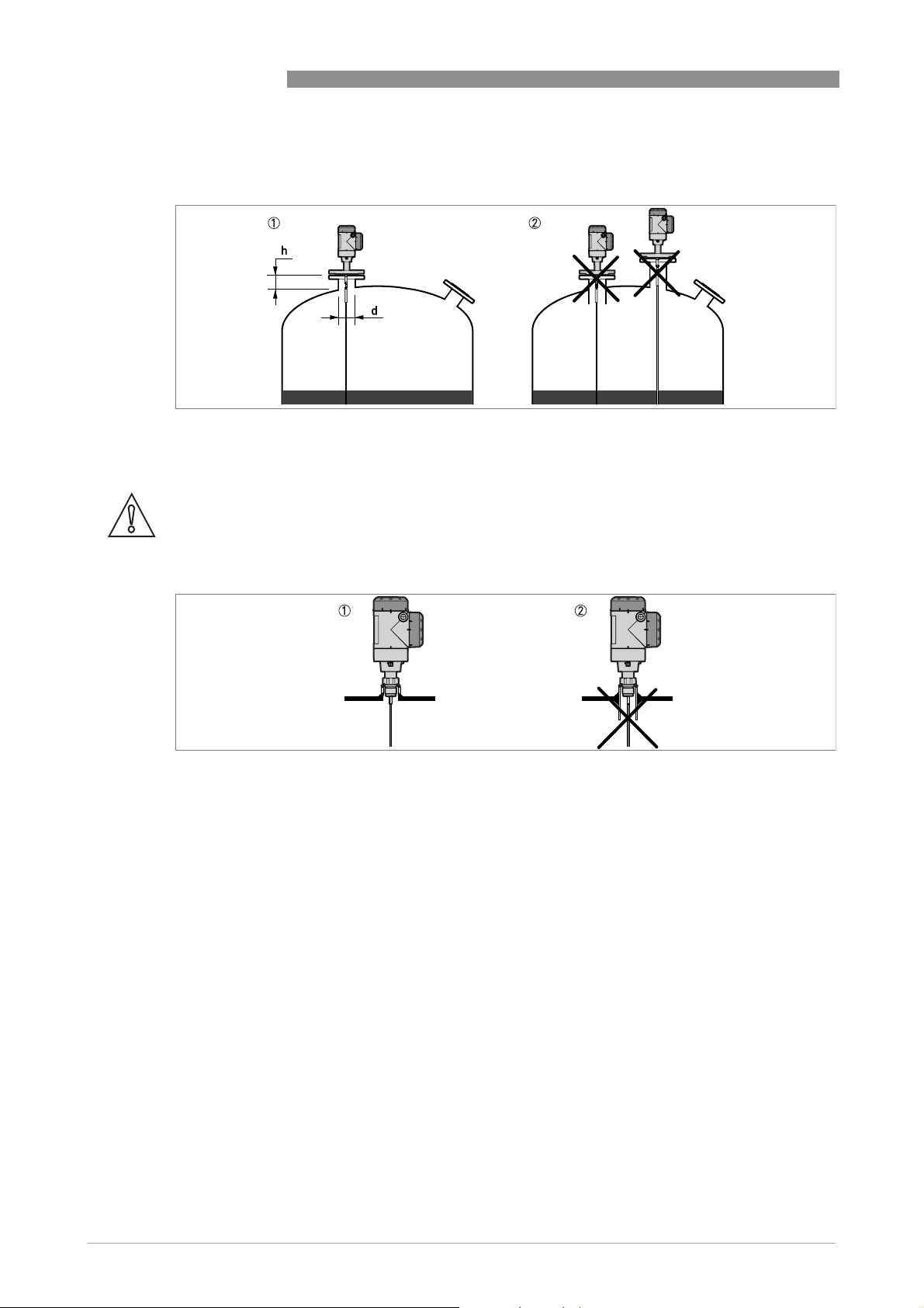
For single cable and single rod probes:
Figure 2-13: Recommended nozzle dimensions for single rod and single cable probes
1 Recommended conditions: h ≤ d, where h is the height of the tank nozzle and d is the diameter of the tank nozzle.
2 The end of the nozzle must not have an extension into the tank. Do not install the device on a high nozzle.
CAUTION!
If the device is installed on a high nozzle, make sure that the probe does not touch the side of the
nozzle (attach the probe end etc.).
OPTIFLEX 2200 C/F
Figure 2-14: Sockets for threaded process connections
1 Recommended installation
2 The end of the socket must not have an extension into the tank
14
www.krohne.com 12/2016 - 4000622105 - QS OPTIFLEX 2200 R05 en
OPTIFLEX 2200 C/F
For double cable and double rod probes:
Figure 2-15: Recommended nozzle dimensions for double rod and double cable probes
d ≥ 50 mm / 2¨, where d is the diameter of the tank nozzle
For coaxial probes:
If your device has a coaxial probe, you can ignore these installation recommendations.
INSTALLATION
2
CAUTION!
Install coaxial probes in clean liquids that are not too viscous.
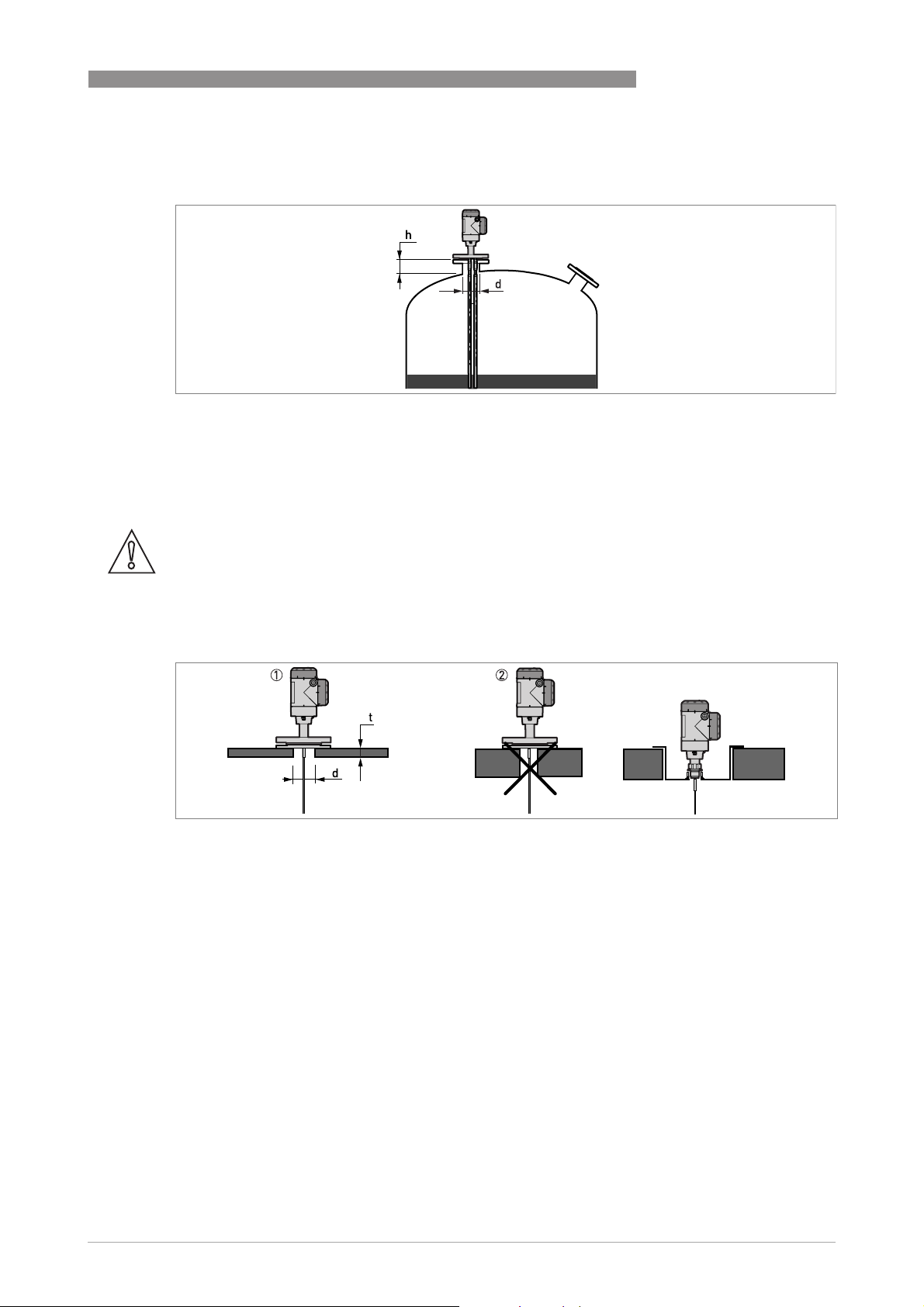
2.7.3 Installation requirements for concrete roofs
Figure 2-16: Installation on a concrete roof
1 The diameter, d, of the hole must be greater than the thickness, t, of the concrete.
2 If the thickness, t, of the concrete is greater than the diameter, d, of the hole, install the device in a recess.
www.krohne.com12/2016 - 4000622105 - QS OPTIFLEX 2200 R05 en
15
2
INSTALLATION
2.8 Installation recommendations for liquids
2.8.1 General requirements
OPTIFLEX 2200 C/F
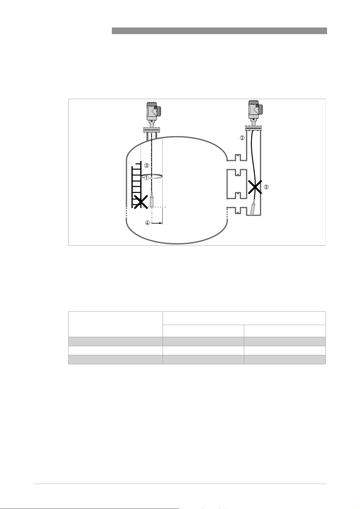
Figure 2-17: Installation recommendations for liquids
1 The electromagnetic (EM) field generated by the device. It has a radius of R
objects and product flow. Refer to the table that follows.
2 If there are too many objects in the tank, install a bypass chamber or stilling well.
3 Keep the probe straight. If the probe is too long, shorten the probe length . Make sur e that t he device is config ured with
the new probe length. For more data on the procedure, refer to the handbook.
4 Empty space. Refer to the table that follows.
. Make sure that the EM field is clear of
min
Clearance between the probe and other objects in the tank
Probe type Empty space (radius, R
[mm] [inches]
Coaxial 0 0
Double rod / cable 100 4
Single rod / cable 300 12
), around the probe
min
16
www.krohne.com 12/2016 - 4000622105 - QS OPTIFLEX 2200 R05 en
OPTIFLEX 2200 C/F
INSTALLATION
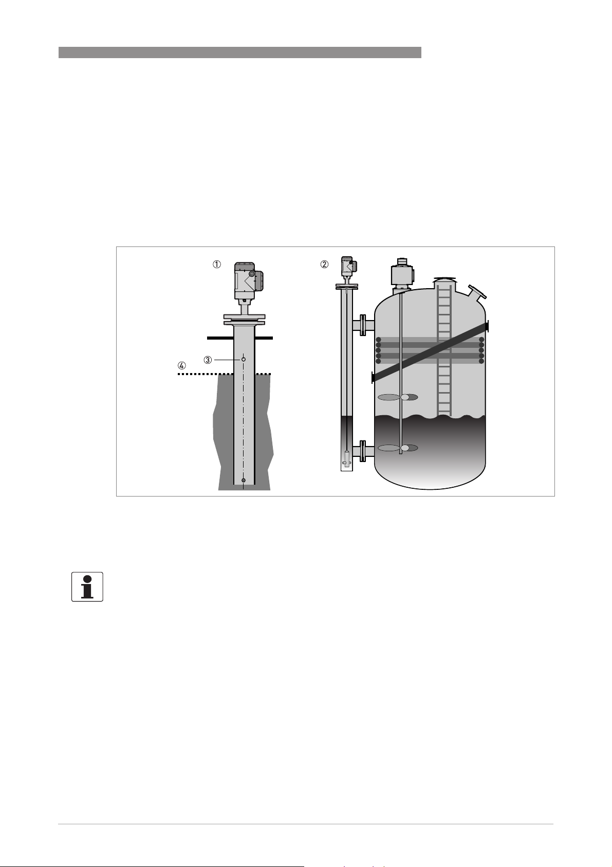
2.8.2 Installation in standpipes (stilling wells and bypass chambers)
Use a standpipe if:
• The liquid is very turbulent or agitated.
• There are too many other objects in the tank.
• The device is measuring a liquid in a tank with a floating roof.
For more data, refer to the Handbook.
2
Figure 2-18: Installation recommendations for standpipes (stilling wells and bypass chambers)
1 Stilling well
2 Bypass chamber
3 Vent
4 Level of the liquid
INFORMATION!
Stilling wells are not necessary for devices with coaxial probes. But if there is a sudden change
in diameter in the stilling well, we recommend that you install a device with a coaxial probe.
www.krohne.com12/2016 - 4000622105 - QS OPTIFLEX 2200 R05 en
17
2
INSTALLATION
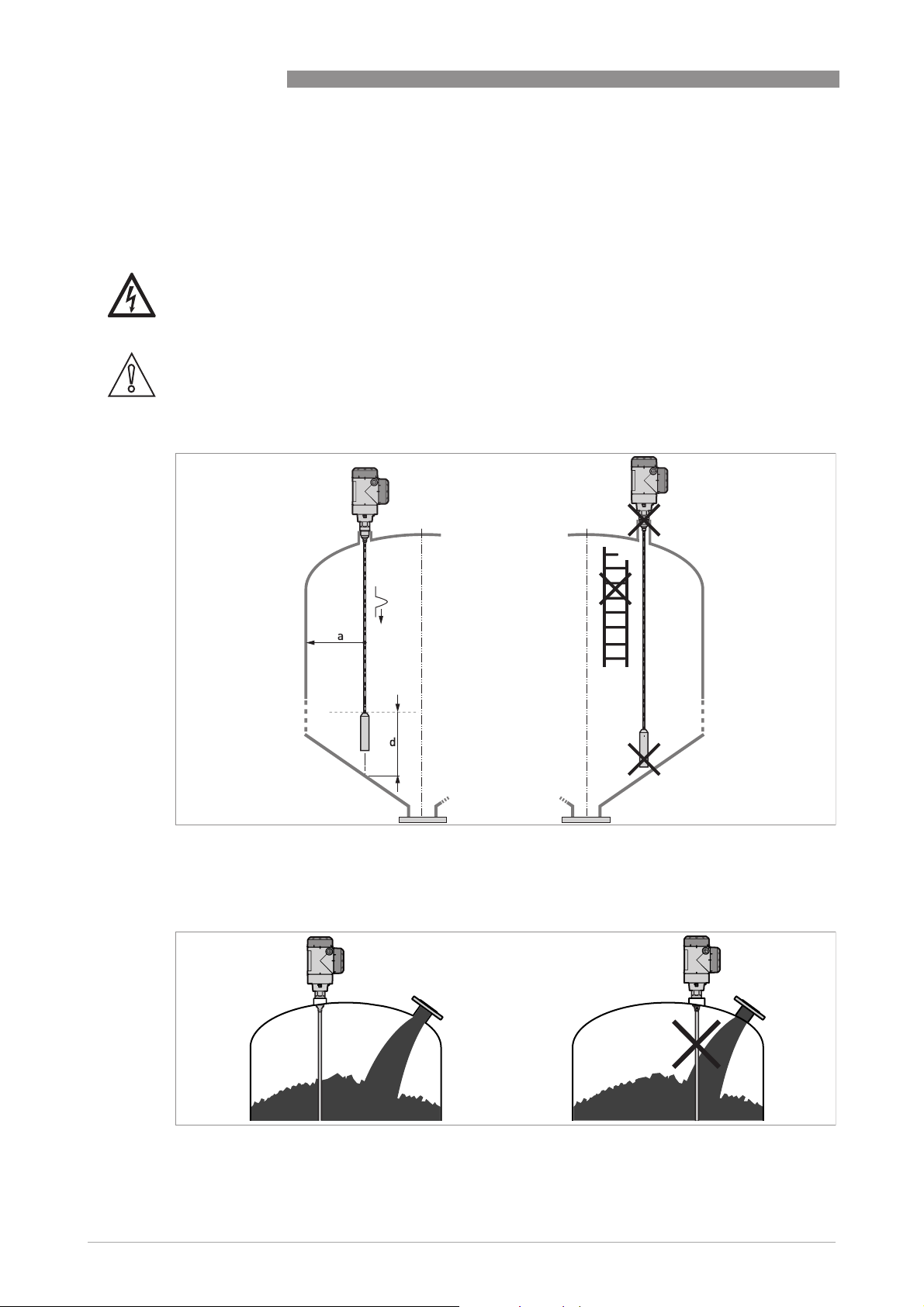
2.9 Installation recommendations for solids
2.9.1 Nozzles on conical silos
We recommend that you prepare the installation when the silo is empty.
DANGER!
Risk of electrostatic discharge (ESD): The device is resistant to electrostatic discharges of up to
30 kV, but it is the responsibility of the fitter and the user to prevent ESD.
CAUTION!
Install the device at the correct location to measure level correctly and prevent too much
bending and traction. If necessary, attach the probe to the bottom of the tank.
OPTIFLEX 2200 C/F
18
Figure 2-19: Installation recommendations for solids
a ≥ 300 mm / 12¨
d ≥ 300 mm / 12¨
Figure 2-20: Do not install the probe near to a product inlet
www.krohne.com 12/2016 - 4000622105 - QS OPTIFLEX 2200 R05 en
 Loading...