

KROHNE OPTICHECK Handbook

Handbook
Handbook
OPTICHECK
OPTICHECK
OPTICHECKOPTICHECK
HandbookHandbook
In-situ verification for field devices (electromagnetic,
mass and vortex flowmeters and level devices)
Electronic revision: ER1.1.0_; SW 4.0.0_
© KROHNE 04/2017 - 4003706304 - MA OPTICHECK R04 en

:
IMPRINT
:::::::::::::::::::::::::::::::::::::::
All rights reserved. It is prohibited to reproduce this documentation, or any part thereof, without
the prior written authorisation of KROHNE Messtechnik GmbH.
Subject to change without notice.
Copyright 2017 by
KROHNE Messtechnik GmbH - Ludwig-Krohne-Str. 5 - 47058 Duisburg (Germany)
2
www.krohne.com 04/2017 - 4003706304 - MA OPTICHECK R04 en

OPTICHECK
CONTENTS
1 Safety instructions 5
1.1 Version history.................................................................................................................. 5
1.2 Intended use ..................................................................................................................... 6
1.3 Certification ...................................................................................................................... 7
1.4 Safety instructions from the manufacturer ..................................................................... 8
1.4.1 Copyright and data protection ................................................................................................ 8
1.4.2 Disclaimer ............................................................................................................................... 8
1.4.3 Product liability and warranty ................................................................................................ 9
1.4.4 Information concerning the documentation........................................................................... 9
1.4.5 Warnings and symbols used................................................................................................. 10
1.5 Safety instructions for the operator............................................................................... 10
2 Device description 11
2.1 Device description .......................................................................................................... 11
2.2 Theory of operation ........................................................................................................12
2.3 Scope of delivery............................................................................................................. 14
2.4 Example nameplate........................................................................................................ 15
3 Installation 16
3.1 Storage ........................................................................................................................... 16
3.2 Transport and usage ...................................................................................................... 16
3.3 Pre-installation requirements ....................................................................................... 16
3.3.1 General notes on installation................................................................................................ 16
3.3.2 Magnetic field........................................................................................................................ 17
3.3.3 Impacts and vibration ........................................................................................................... 17
3.3.4 Electrostatic discharge......................................................................................................... 18
3.3.5 Software installation............................................................................................................. 18
3.3.6 Signal converter specific information .................................................................................. 19
4 Electrical connections 20
4.1 Safety instructions.......................................................................................................... 20
4.2 Connection to the tablet ................................................................................................. 21
4.3 Connection of device.......................................................................................................21
4.4 Connection of OPTIFLUX / TIDALFLUX / WATERFLUX flowmeters............................... 25
4.4.1 Connection of IFC 050 ........................................................................................................... 25
4.4.2 Connection of IFC 070 ........................................................................................................... 31
4.4.3 Connection of IFC 100 ........................................................................................................... 36
4.4.4 Connection of IFC 300 ........................................................................................................... 41
4.4.5 Connection of IFC 300 compact and field versions .............................................................. 42
4.4.6 Connection of IFC 300 wall version ...................................................................................... 48
4.5 Connection of OPTIMASS flowmeters............................................................................ 52
4.5.1 Connection of MFC 300 / MFC 400........................................................................................ 53
4.5.2 Connection of MFC 300 / MFC 400 compact and field versions........................................... 55
4.5.3 Connection of MFC 300 wall version .................................................................................... 59
www.krohne.com04/2017 - 4003706304 - MA OPTICHECK R04 en
3

CONTENTS
OPTICHECK
4.6 Connection of OPTISWIRL flowmeters........................................................................... 62
4.6.1 Connection of VFC 200 .......................................................................................................... 63
4.6.2 Connection of VFC 200 compact version .............................................................................. 64
4.7 Connection of OPTIWAVE level meter............................................................................ 69
4.7.1 Connection of RLC 400.......................................................................................................... 69
4.7.2 Connection of RLC 400 compact version.............................................................................. 70
5 Start-up 74
5.1 Quick start of software ................................................................................................... 74
5.2 Launch application .........................................................................................................75
5.3 Start page ....................................................................................................................... 76
5.4 Configuration page .........................................................................................................78
5.5 Application page ............................................................................................................. 79
5.6 Verification page ............................................................................................................. 80
5.7 Reconnection page ......................................................................................................... 81
5.8 Result page..................................................................................................................... 82
5.8.1 Factory settings .................................................................................................................... 83
5.8.2 Verification history ................................................................................................................ 84
5.8.3 Description of the certificate ................................................................................................ 85
5.8.4 Description of the verification report ...................................................................................86
5.9 About page...................................................................................................................... 88
6 Service 89
6.1 Software update ............................................................................................................. 89
6.2 Calibration of the verification box .................................................................................. 89
6.3 Spare parts ..................................................................................................................... 90
6.4 Availability of services .................................................................................................... 91
6.5 Repairs............................................................................................................................ 91
6.6 Defect components......................................................................................................... 91
6.7 Returning the device to the manufacturer..................................................................... 92
6.7.1 General information.............................................................................................................. 92
6.7.2 Form (for copying) to accompany a returned device............................................................ 93
6.8 Disposal .......................................................................................................................... 93
7 Technical data 94
7.1 Technical data................................................................................................................. 94
4
www.krohne.com 04/2017 - 4003706304 - MA OPTICHECK R04 en

OPTICHECK
1.1 Version history
The version is defined:
• for the hardware by the ER (Electronic Revision) mark on the verification box
• for the software by the version indication on the start page of the software on the tablet /
laptop
The version indication is divided into a prefix and 3 position, which are separated by points,
followed by a suffix:
(prefix)(position 1).(position 2).(position 3)(suffix)
Example: ER1.0.0_
• the prefix indicates an Electronic Revision (ER) or Software Version (Version)
• the first position: indicates an incompatible change
• the second position: indicates a functional enhancement, which is backward compatible
• the third position: indicates a bug fix, which does not change anything to this handbook
• The suffix is an underscore or space for all released versions. Trial versions or development
versions may have different suffixes
SAFETY INSTRUCTIONS
1
Release date Electronic revision Changes and
Documentation
compatibility
2014 ER 1.0.0_; SW 1.0.0_ - MA OPTICHECK R01
05/2015 ER 1.0.0_; SW 2.0.1_ Mass flowmeter
verification added
09/2016 ER 1.1.0_; SW 3.0.1_ Vortex flowmeter
verification added
03/2017 ER 1.1.0_; SW 4.0.0_ Radar level verification
added
MA OPTICHECK R02
MA OPTICHECK R03
MA OPTICHECK R04
www.krohne.com04/2017 - 4003706304 - MA OPTICHECK R04 en
5

1
SAFETY INSTRUCTIONS
1.2 Intended use
INFORMATION!
This device is a Group 1, Class A device as specified within CISPR11:2009. It is intended for use in
industrial environment. There may be potential difficulties in ensuring electromagnetic
compatibility in other environments, due to conducted as well as radiated disturbances.
INFORMATION!
The manufacturer is not liable for any damage resulting from improper use or use for other than
the intended purpose.
OPTICHECK is a portable testing and verification tool for field devices. It allows the operator to
check the functionality and accuracy of the field device, without the need to remove the device
from the process. The OPTICHECK operates on the power supply from tablet/laptop and needs
no other power supply. It is intended to be operated for a short duration of measuring time only.
If RF transmitters are used in close proximity, the equipment may be disturbed.
A tablet is a sensitive equipment. For charging use surge protection equipment MNT-1 D
(Phoenix Contact). In case of OPTICHECK operating with a laptop, ensure that laptop and charger
are suited for the industrial electromagnetic environment.
OPTICHECK
OPTICHECK is not meant or able to perform tests on communication interfaces such as HART
®
Profibus
output, pulse and frequency outputs and status outputs as well as control and current inputs.
, Foundation Fieldbus®, Modbus or other buses. It is built to perform tests on current
®
Faulty installation
To measure accurately both the field device and the signal converter must be installed correctly.
Measurement errors caused by faulty installation (mechanical and/or electrical) or minor
defects on the sensor, may not be detected by the OPTICHECK.
An electromagnetic or vortex field device that has been verified by the OPTICHECK will measure
within ±1% of the original factory calibration. Please note that on site verification with the
OPTICHECK is not intended to replace a full wet calibration on a calibration rig.
DANGER!
OPTICHECK is not Ex certified and must not be used in areas with an explosive atmosphere.
Do not connect the OPTICHECK to a sensor or a signal converter if an explosive atmosphere may
exist. Signal converters intended for Ex configurations can only be verified in a safe area.
LEGAL NOTICE!
OPTICHECK is not designed to verify devices used in custody transfer applications. To perform a
verification, the seals of the device have to be broken. There is no approval of OPTICHECK for
these types of applications.
,
WARNING!
Only use OPTICHECK on signal converters that are listed as compatible. Using OPTICHECK on
field devices that are not compatible may cause damage to the signal converter or OPTICHECK.
If the device is not used according to the operating conditions (refer to chapter "Technical data")
the intended protection could be affected.
6
www.krohne.com 04/2017 - 4003706304 - MA OPTICHECK R04 en

OPTICHECK
1.3 Certification
CE marking
The device fulfils the statutory requirements of the following EU directives:
• For devices with electrical installations: EMC directive
The manufacturer certifies successful testing of the product by applying the CE mark.
An EU declaration of conformity regarding the directives in question and the associated
harmonised standards can be downloaded from our website.
SAFETY INSTRUCTIONS
1
www.krohne.com04/2017 - 4003706304 - MA OPTICHECK R04 en
7

1
SAFETY INSTRUCTIONS
1.4 Safety instructions from the manufacturer
1.4.1 Copyright and data protection
The contents of this document have been created with great care. Nevertheless, we provide no
guarantee that the contents are correct, complete or up-to-date.
The contents and works in this document are subject to copyright. Contributions from third
parties are identified as such. Reproduction, processing, dissemination and any type of use
beyond what is permitted under copyright requires written authorisation from the respective
author and/or the manufacturer.
The manufacturer tries always to observe the copyrights of others, and to draw on works created
in-house or works in the public domain.
The collection of personal data (such as names, street addresses or e-mail addresses) in the
manufacturer's documents is always on a voluntary basis whenever possible. Whenever
feasible, it is always possible to make use of the offerings and services without providing any
personal data.
OPTICHECK
We draw your attention to the fact that data transmission over the Internet (e.g. when
communicating by e-mail) may involve gaps in security. It is not possible to protect such data
completely against access by third parties.
We hereby expressly prohibit the use of the contact data published as part of our duty to publish
an imprint for the purpose of sending us any advertising or informational materials that we have
not expressly requested.
1.4.2 Disclaimer
The manufacturer will not be liable for any damage of any kind by using its product, including,
but not limited to direct, indirect or incidental and consequential damages.
This disclaimer does not apply in case the manufacturer has acted on purpose or with gross
negligence. In the event any applicable law does not allow such limitations on implied warranties
or the exclusion of limitation of certain damages, you may, if such law applies to you, not be
subject to some or all of the above disclaimer, exclusions or limitations.
Any product purchased from the manufacturer is warranted in accordance with the relevant
product documentation and our Terms and Conditions of Sale.
The manufacturer reserves the right to alter the content of its documents, including this
disclaimer in any way, at any time, for any reason, without prior notification, and will not be liable
in any way for possible consequences of such changes.
8
www.krohne.com 04/2017 - 4003706304 - MA OPTICHECK R04 en

OPTICHECK
1.4.3 Product liability and warranty
The operator shall bear responsibility for the suitability of the device for the specific purpose.
The manufacturer accepts no liability for the consequences of misuse by the operator. Improper
installation or operation of the devices (systems) will cause the warranty to be void. The
respective "Standard Terms and Conditions" which form the basis for the sales contract shall
also apply.
1.4.4 Information concerning the documentation
To prevent any injury to the user or damage to the device it is essential that you read the
information in this document and observe applicable national standards, safety requirements
and accident prevention regulations.
If this document is not in your native language and if you have any problems understanding the
text, we advise you to contact your local office for assistance. The manufacturer can not accept
responsibility for any damage or injury caused by misunderstanding of the information in this
document.
This document is provided to help you establish operating conditions, which will permit safe and
efficient use of this device. Special considerations and precautions are also described in the
document, which appear in the form of icons as shown below.
SAFETY INSTRUCTIONS
1
www.krohne.com04/2017 - 4003706304 - MA OPTICHECK R04 en
9
1
SAFETY INSTRUCTIONS
1.4.5 Warnings and symbols used
Safety warnings are indicated by the following symbols.
DANGER!
This warning refers to the immediate danger when working with electricity.
DANGER!
This warning refers to the immediate danger of burns caused by heat or hot surfaces.
DANGER!
This warning refers to the immediate danger when using this device in a hazardous atmosphere.
DANGER!
These warnings must be observed without fail. Even partial disregard of this warning can lead to
serious health problems and even death. There is also the risk of seriously damaging the device
or parts of the operator's plant.
OPTICHECK
WARNING!
Disregarding this safety warning, even if only in part, poses the risk of serious health problems.
There is also the risk of damaging the device or parts of the operator's plant.
CAUTION!
Disregarding these instructions can result in damage to the device or to parts of the operator's
plant.
INFORMATION!
These instructions contain important information for the handling of the device.
LEGAL NOTICE!
This note contains information on statutory directives and standards.
• HANDLING
HANDLING
HANDLINGHANDLING
This symbol designates all instructions for actions to be carried out by the operator in the
specified sequence.
i RESULT
RESULT
RESULTRESULT
This symbol refers to all important consequences of the previous actions.
1.5 Safety instructions for the operator
10
WARNING!
In general, devices from the manufacturer may only be installed, commissioned, operated and
maintained by properly trained and authorized personnel.
This document is provided to help you establish operating conditions, which will permit safe and
efficient use of this device.
www.krohne.com 04/2017 - 4003706304 - MA OPTICHECK R04 en

OPTICHECK
2.1 Device description
This measuring tool is designed for the fully automated analysis and verification of field devices
in combination with signal converters.
Your measuring tool is supplied ready for operation. The factory settings for the operating data
have been made in accordance with your order specifications.
DEVICE DESCRIPTION
2
Figure 2-1: Available versions
1 Complete version (incl. tablet)
2 Version with ONLY the verification box (incl. suitcase with cabling)
INFORMATION!
For details on specific demands or choice of version please contact the manufacturer.
www.krohne.com04/2017 - 4003706304 - MA OPTICHECK R04 en
11
2
DEVICE DESCRIPTION
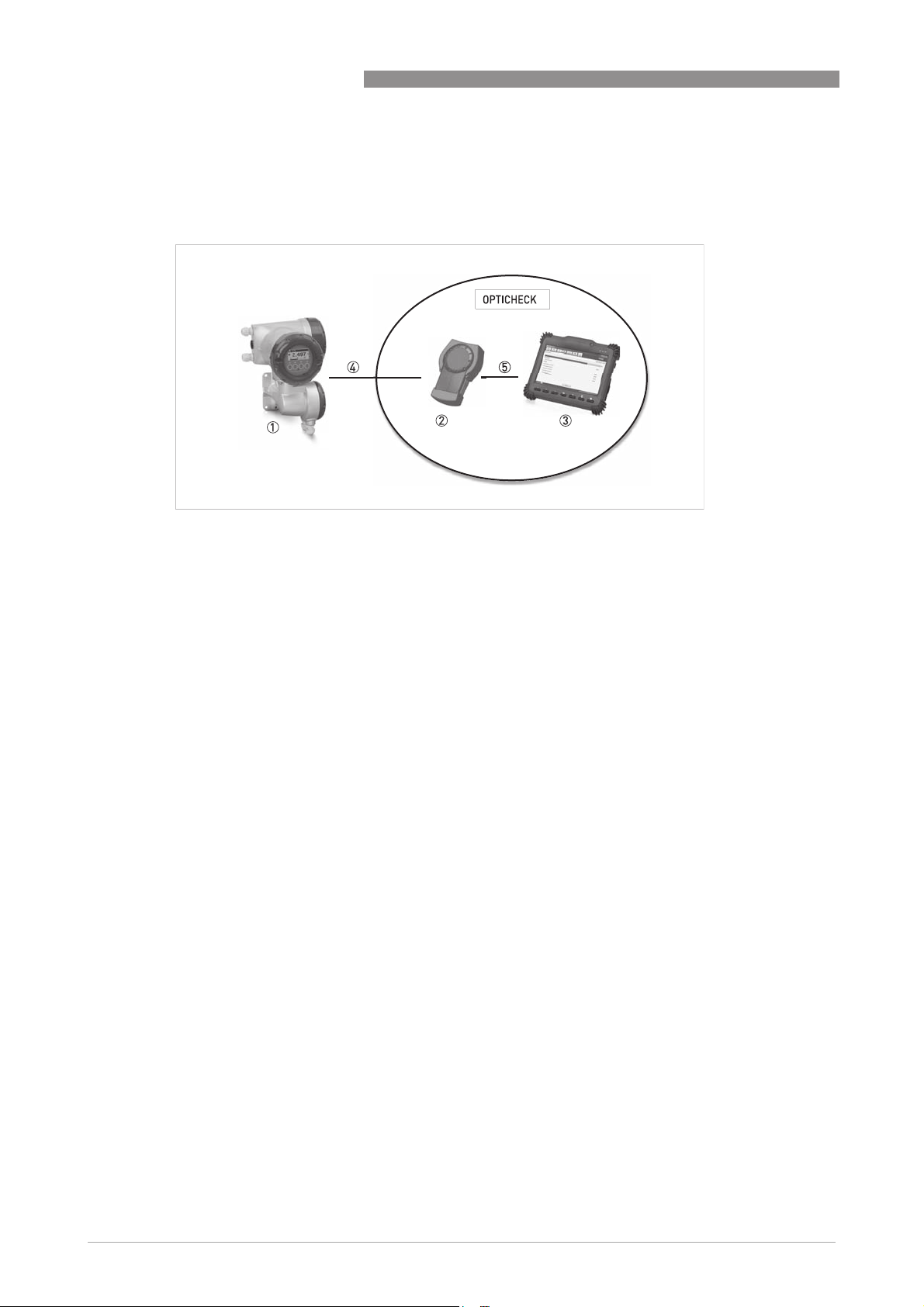
2.2 Theory of operation
Design and connection of the device
Figure 2-2: Connection diagram
1 Device Under Test (DUT)
2 Verification box
3 Tablet
4 Adapter
5 USB
OPTICHECK
The OPTICHECK consists of:
• Verification box including all the electronic hardware and software for the measurements
• Rugged tablet or PC with a USB connection to the verification box including the control and
evaluation software (for the sequential tests performed by the verification box)
• USB connection cable to connect the verification box with the tablet / laptop
• Different adapters to connect various KROHNE field devices (DUT) to the verification box
12
www.krohne.com 04/2017 - 4003706304 - MA OPTICHECK R04 en
OPTICHECK
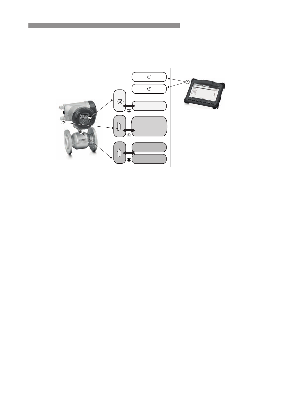
Verification box
DEVICE DESCRIPTION
2
Figure 2-3: Block diagram of verification box
1 Serial <-> USB
2 Galvanically isolated power supply (via the USB interface from the tablet)
3 GDC connection (galvanically isolated)
- interface connects the OPTICHECK to the internal communication interface of the field device
4 I/O connections
- connects (and if required supplies) to the I/O circuitry of the field device via a multiplexer
- I/O measurement and supply, up to 4 different I/O channels
- voltage, current, and frequency measurement possible
- voltage or current supply possible
5 Sensor connection
- sensor simulation; supplies calibrated test signals to the sensor input of the signal converter
- sensor measurement; connects to the sensor and is able to perform different measurements
6 Tablet
7 GDC terminal on field device position (depends on field device)
8 Sensor connection on field device (depends on field device)
9 I/O connection on field device (depends on field device)
www.krohne.com04/2017 - 4003706304 - MA OPTICHECK R04 en
13
2
DEVICE DESCRIPTION
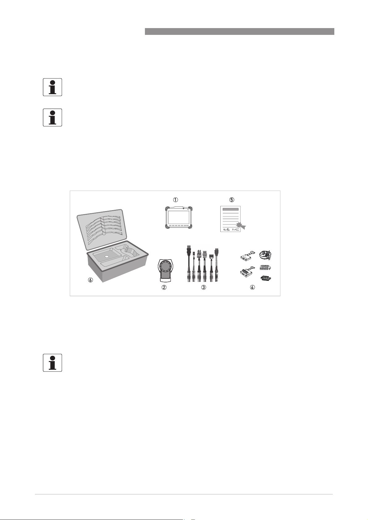
2.3 Scope of delivery
INFORMATION!
Do a check of the packing list to make sure that you have all the elements given in the order.
INFORMATION!
Inspect the packaging carefully for damages or signs of rough handling. Report damage to the
carrier and to the local office of the manufacturer.
Complete version
The complete version of the OPTICHECK is delivered with all connection cables, adapting tools
and all necessary software installed on the tablet, together with the documentation, in a shockproof suitcase which is specially designed for the OPTICHECK.
OPTICHECK
Figure 2-4: Scope of delivery (complete version)
1 Ordered tablet (optional)
2 Verification box
3 Adapter cables
4 I/O parking plug and measurement device specific adapters
5 Certificates (additional software and information)
6 Shock-proof suitcase
INFORMATION!
Assembly materials and tools are not part of the delivery. Use the assembly materials and tools
in compliance with the applicable occupational health and safety directives.
14
www.krohne.com 04/2017 - 4003706304 - MA OPTICHECK R04 en

OPTICHECK
2.4 Example nameplate
INFORMATION!
Look at the device nameplate to ensure that the device is delivered according to your order.
Figure 2-5: Example nameplate
1 Name and address of the manufacturer
2 Product name
3 CE marking (EU conformity)
4 Electronic/electric device waste marking (WEEE dustbin symbol)
5 Year of manufacturing
6 Website of manufacturer
7 Electronic revision, reference to documentation and bar code
8 Information about production batch, serial number and production order
DEVICE DESCRIPTION
2
www.krohne.com04/2017 - 4003706304 - MA OPTICHECK R04 en
15

3
INSTALLATION
3.1 Storage
• Store the device in a dry and dust free location.
• Avoid lasting direct exposure to the sun.
• Store the device in its original packaging.
• Storage temperature: -20...+60°C / -4...+140°F
• Humidity: 0...90% non-condensing
3.2 Transport and usage
• Use the included suitcase to transport the OPTICHECK.
Notes on handling the device
• Do not carry the device by the connected wires.
• Avoid heavy vibrations.
• Avoid heavy mechanically shocks or impacts on the device.
OPTICHECK
3.3 Pre-installation requirements
Make sure that you have all necessary tools available:
• Allen key (4 mm)
• Philips screwdriver (No. 2)
• Small screwdriver
3.3.1 General notes on installation
INFORMATION!
The installation of the OPTICHECK verification tool always has to be done on the signal converter
side.
CAUTION!
Avoid extensive humidity and/or direct entry of rain, when measuring / working with the
OPTICHECK, during the verification process or when the housing of the signal converter is open.
Installation of the OPTICHECK verification tool and the tablet, mechanically and electrically,
together with the use of software and installation of special drivers, is only permitted to specially
trained personal.
The service engineer and/or operator has to know the correct handling of the OPTICHECK tool,
as well as servicing and operating sensor/signal converter combinations.
16
Please contact the manufacturer or your local sales office, for the availability of training and
information tools.
www.krohne.com 04/2017 - 4003706304 - MA OPTICHECK R04 en

OPTICHECK
For a reliable and high accuracy measurement, it is essential to follow the installation
requirements as specified in the manual of the related field device. Neither wet calibration in a
calibration rig nor OPTICHECK are able to include verification of installation/application
conditions.
Take special care of:
• Grounding conditions of the field device
3.3.2 Magnetic field
INSTALLATION
3
Figure 3-1: Avoid magnetic fields
CAUTION!
In order to use OPTICHECK with compatible field devices, their housing has to be opened for
required cable connections. In this case, OPTICHECK and the connected field device are to some
extend sensitive to high electromagnetic radiation. If this temporary disturbance influences the
operation or verification process, a device reset or power cycle can become necessary to restore
normal operation.
3.3.3 Impacts and vibration
Figure 3-2: Avoid high impacts or vibration
CAUTION!
The OPTICHECK setup has been designed to be as robust as possible. To ensure reliability,
accuracy and long life time the following has to be respected:
Be careful, not to drop the device and take special attention on the way the device is attached
and/or placed on a particular surface.
www.krohne.com04/2017 - 4003706304 - MA OPTICHECK R04 en
17

3
INSTALLATION
3.3.4 Electrostatic discharge
CAUTION!
The OPTICHECK is connected to the signal converter of the field device. The housing of the field
device has to be opened for these connections.
Extensive humidity and direct rain has to be avoided during verification.
The signal converter is to some extend sensitive to ESD (electrostatic discharge). To prevent a
failing verification or even damage:
OPTICHECK
• Do not touch any electrical contact directly!
• Make sure to discharge yourself by wearing a wrist strap.
• If no wrist strap is available, ground yourself by touching a metal surface that is grounded.
3.3.5 Software installation
The tablet delivered with OPTICHECK comes with a pre-installed Windows and the OPTICHECK
application and drivers.
If OPTICHECK should be used with a different tablet or notebook, 32 bit or 64 bit versions for
Microsoft Windows
available via the KROHNE Downloadcenter.
Start the Windows install wizard with a double-click on the setup file (administrator rights
required). The user will be guided through the installation process. Follow the instructions given.
The following components are installed:
• OPTICHECK application software
• USB driver for OPTICHECK
©
can be selected depending on the target system. The recent version is
18
www.krohne.com 04/2017 - 4003706304 - MA OPTICHECK R04 en

OPTICHECK
3.3.6 Signal converter specific information
For more detailed information regarding basic instructions on how to operate signal converters,
please consult applicable manual of addendum of the IFC 050, IFC 070, IFC 100, IFC 300,
MFC 300, MFC 400, VFC 200 and RLC 400 signal converters, respectively. The same applies for
the following signal converter related topics:
• connection diagram (electrical and I/O and detailed information regarding electrical
connection)
• cable requirements, cable preparation and lengths
• explanation of data and markings on nameplates or CG numbering
• mechanical mounting of signal converters
• software and electronics versions and revisions
• menu and operating actions
INSTALLATION
3
www.krohne.com04/2017 - 4003706304 - MA OPTICHECK R04 en
19

4
ELECTRICAL CONNECTIONS
The OPTICHECK is suited to be used with the electromagnetic flowmeter families OPTIFLUX,
TIDALFLUX and WATERFLUX, the vortex flowmeter family OPTISWIRL, the mass flowmeter
family OPTIMASS as well as the radar level family OPTIWAVE.
There is no need for an external power connection since the OPTICHECK verification box itself is
fully powered over USB. However, the device under test (DUT) must be externally powered
during verifications (except the battery powered device IFC 070 and the loop-powered devices).
The OPTICHECK can perform a fully automated verification of all compatible field devices in
order to verify the accuracy of the signal converter. Depending on the field device type, the
sensor is verified – either by physical check of its electric characteristics or by firmware-internal
diagnostic functions. Therefore, it is not necessary to remove the field device from the process
environment (except cabling) for the verification.
Different types of verifications are available which provide different depths of verification
depending on the type of the DUT – ranging from device-internal diagnostics to full electrical
verification of, for instance, input and output circuits. For all levels, a detailed test report and
certificate can be generated after verification. For more information refer to
verification report
on page 86.
OPTICHECK
Description of the
OPTICHECK is supplied with all the connection cables and adapters for the signal converters of
the afore-mentioned field device series and a USB cable for connection to the tablet. The
following sections describe how to connect the OPTICHECK verification box to the supported
signal converter variants.
4.1 Safety instructions
DANGER!
All work on the electrical connections may only be carried out with the power disconnected.
DANGER!
Observe the national regulations for electrical installations!
DANGER!
For devices used in hazardous areas, additional safety notes apply; please refer to the Ex
documentation.
WARNING!
Observe without fail the local occupational health and safety regulations. Any work done on the
electrical components of the measuring device may only be carried out by properly trained
specialists.
20
www.krohne.com 04/2017 - 4003706304 - MA OPTICHECK R04 en

OPTICHECK
4.2 Connection to the tablet
CAUTION!
The tablet/laptop shall not be connected to its charger when connected to a measurement
device.
INFORMATION!
•
A tablet is a sensitive equipment. For charging use surge protection equipment MNT-1 D
(Phoenix Contact). In case of OPTICHECK operating with a laptop, ensure that laptop and
charger are suited for the industrial electromagnetic environment.
•
The USB connection shall be connected to electrical circuits that ensure a safe separation
only (e.g. acc. to IEC 60950-1).
•
The HDMI cable and connectors shall not be used with other equipment than the OPTICHECK
verification box (e.g. TVs)
The OPTICHECK verification box is connected via USB to the delivered tablet or a Windows based
laptop.
ELECTRICAL CONNECTIONS
4
Figure 4-1: USB connection cable (blue marking)
4.3 Connection of device
The only mandatory connection to a DUT is the connection cable with green marking to ground
and to the service interface:
Figure 4-2: Service interface connection cable (green marking)
The necessity of the other connection cables depends on the field device variant and the desired
verification depth.
www.krohne.com04/2017 - 4003706304 - MA OPTICHECK R04 en
21

4
ELECTRICAL CONNECTIONS
The next figure depicts the included I/O cables (red marking) for connecting a signal converter’s
inputs and outputs:
OPTICHECK
Figure 4-3: I/O connection cables (red marking)
1 Standard I/O connection cable with separate pins (IFC 070 / 100 / 300, VFC 200, MFC 300 / 400 and RLC 400)
2 I/O connection cable for wall version (IFC 300 and MFC 300)
3 I/O connection cable for built-in diagnostic interface (IFC 050)
4 I/O adapter for IFC 300 and MFC 300 / 400
In order to connect OPTICHECK to the sensor and sensor electronics (if supported by the
measurement device) the standard sensor connection cable (black marking) is connected to one
of the device specific sensor adapters:
Figure 4-4: Standard sensor connection cable
1 Standard sensor connection cable
2 HDMI connector for connection of measurement device specific adapters
22
www.krohne.com 04/2017 - 4003706304 - MA OPTICHECK R04 en

OPTICHECK
ELECTRICAL CONNECTIONS
Figure 4-5: EMF sensor connection adapter for IFC 050, IFC 070, IFC 100 and IFC 300
1 Female connector (blue) for connecting to sensor terminal of the IFC 050 (variant 1) and IFC 070, IFC 100 as well as
IFC 300 (variant 2)
2 HDMI connector for connection of the standard sensor connection cable
3 Male connector (black) for connecting to female connector (blue) of sensor cable (of the measurement device)
4 Connectors for remote versions (field and wall-mounted)
4
Figure 4-6: Vortex flowmeter sensor connection adapter
1 Sensor adapter for VFC 200 (front)
2 Connector for service interface connection cable (green marking)
3 HDMI connector for standard sensor connection cable (black marking)
4 Connectors for the display unit of the VFC 200
5 Sensor adapter for VFC 200 (back)
6 Connection for the sensor cable of the measurement device
www.krohne.com04/2017 - 4003706304 - MA OPTICHECK R04 en
23

4
ELECTRICAL CONNECTIONS
Additionally there is the I/O "parking" adapter for the I/O cables, which are removed from a DUT.
It is used to protect against short circuiting and to mark the cables for easier reconnection:
Figure 4-7: I/O parking plug
The required signal converter-specific instructions are described separately in the following
sections, which are structured as follows:
• Step 1: Overview and access to the housing versions (compact, remote and wall)
• Step 2: Cabling instructions for signal converter / sensor combinations
• Step 3: Conducting the verification
• Step 4: Reconnecting the device after verification
OPTICHECK
24
www.krohne.com 04/2017 - 4003706304 - MA OPTICHECK R04 en

OPTICHECK
ELECTRICAL CONNECTIONS
4.4 Connection of OPTIFLUX / TIDALFLUX / WATERFLUX flowmeters
The electromagnetic flowmeter families OPTIFLUX and TIDALFLUX equipped with IFC 050 /
IFC 100 / IFC 300 signal converters can be verified in three different depths: either verification is
performed via device-internal diagnostic functions without the need of disconnecting any
electrical connection (level 0 and level 1) or with a full electrical verification of the signal
converter and flow sensor (level 2).
A level 0 verification
level 0 verification (if supported by the connected signal converter) performs a number of tests
level 0 verificationlevel 0 verification
without the requirement of removing the flowmeter from the process environment or removing
electrical connections to the control station. The signal converter is also not disconnected from
the flow sensor. The only required connection to the flowmeter is the GDC service interface. In
this case, the depth of verification is limited, but the measurement will not be interrupted.
4
In addition to a level 0 verification a level 1 verification
supported by the connected signal converter). No additional connections are required, but the
measurement is interrupted.
A level 2 verification
level 2 verification is possible if all electrical connections of the signal converter (except
level 2 verificationlevel 2 verification
IFC 050) are removed from the process environment and the flow sensor, including installations
of the electronic inserts (IFC 300). In this case, OPTICHECK connects to all terminals (GDC, flow
sensor and I/O's) in order to perform a full electrical verification of the signal converter's
measurement accuracy.
4.4.1 Connection of IFC 050
Electromagnetic flowmeters equipped with IFC 050 signal converters can be verified with
OPTICHECK in the following versions:
• Compact version (the signal converter is mounted directly on the flow sensor)
• Remote version (electrical connection to the flow sensor via field current and signal cable)
level 1 verification also performs signal simulations (if
level 1 verificationlevel 1 verification
Figure 4-8: IFC 050 – available versions
1 Compact version
2 Remote version
www.krohne.com04/2017 - 4003706304 - MA OPTICHECK R04 en
25

4
ELECTRICAL CONNECTIONS
In combination with the available OPTIFLUX and WATERFLUX flow sensor types, the following
combinations of signal converter and flow sensor can be verified with OPTICHECK:
Flow sensor Flow sensor + signal converter IFC 050
Compact Remote wall-mounted housing
OPTIFLUX 1000 OPTIFLUX 1050 C OPTIFLUX 1050 W
OPTIFLUX 2000 OPTIFLUX 2050 C OPTIFLUX 2050 W
OPTIFLUX 4000 OPTIFLUX 4050 C OPTIFLUX 4050 W
OPTIFLUX 6000 OPTIFLUX 6050 C OPTIFLUX 6050 W
WATERFLUX 3000 WATERFLUX 3050 C WATERFLUX 3050 W
Connecting to OPTICHECK
Connecting to OPTICHECK
Connecting to OPTICHECKConnecting to OPTICHECK
To connect the required OPTICHECK test cables on the IFC 050 (remote and compact version),
the housing has to be opened. The following steps illustrate how to open the housing of the
IFC 050 and connect/disconnect the necessary cables for all connections.
STEP 1: Start
STEP 1: Start
STEP 1: StartSTEP 1: Start
OPTICHECK
DANGER!
Before connecting the OPTICHECK to the device, make sure to discharge yourself (e.g. by
wearing a wrist strap or touching a metal surface that is grounded). Electrostatic discharge can
damage electronic parts.
• Open the IFC 050 housing by unscrewing the 4 Phillips screws (PH2 screw head).
The next figures show the electronics module of the IFC 050 and in detail the terminals
necessary for all connections:
26
Figure 4-9: IFC 050 electronics module
www.krohne.com 04/2017 - 4003706304 - MA OPTICHECK R04 en

OPTICHECK
Figure 4-10: IFC 050 electronics – connector overview
1 GDC connector
2 I/O diagnostic connector
3 Sensor diagnostic connector
ELECTRICAL CONNECTIONS
4
Figure 4-11: IFC 050 – connection of GDC cable
1 GDC connectors
2 GDC connection cable (green marking)
3 Grounding clip
• Connect the grounding clip 3 of the GDC cable (green marking) to a position suitable for
electrical grounding.
• Connect the GDC cable (green marking) to the connection terminal of the electronics 1.
• Press "Connect" on page "Start" on the screen of tablet / laptop if the device identification
does not start automatically. The device information and status are then collected and the
product image should be displayed.
www.krohne.com04/2017 - 4003706304 - MA OPTICHECK R04 en
27

4
ELECTRICAL CONNECTIONS
STEP 2: Configuration
STEP 2: Configuration
STEP 2: ConfigurationSTEP 2: Configuration
In combination with the IFC 050 the OPTICHECK supports two different options for sensor
verification which can be chosen in the OPTICHECK application.
OPTICHECK
1. Verification without
2. Verification with dedicated sensor tests
Continue with the following procedures to connect the flowmeter’s sensor electronics and the
flow sensor with OPTICHECK:
without dedicated sensor tests (only internal diagnostic functions are used)
withoutwithout
OPTION 1 (without sensor tests)
Figure 4-12: IFC 050 – connection of sensor cable (OPTION 1)
1 Connector for built-in sensor diagnostic
2 IFC 050 sensor connection adapter
• Connect the IFC 050 sensor connection adapter 2 to the connection terminal of the
electronics 1.
• Connect the standard sensor connection cable (black marking) with the IFC 050 sensor
connection adapter.
28
www.krohne.com 04/2017 - 4003706304 - MA OPTICHECK R04 en

OPTICHECK
OPTION 2 (with sensor tests)
ELECTRICAL CONNECTIONS
4
Figure 4-13: IFC 050 – connection of sensor cable (OPTION 2)
1 Connector for built-in sensor diagnostic
2 IFC 050 sensor connection adapter
3 Connector for flow sensor cable (compact version)
4 Sensor cable connector of the IFC 050 adapter (compact version)
5 Connector for flow sensor cable (remote version)
6 Sensor cable connector of the IFC 050 (remote version)
• Connect the IFC 050 sensor connection adapter 2 to the connection terminal of the
electronics 1.
• Connect the flow sensor cable from connector 3 (compact) or 5 (remote) to the sensor cable
connector of the IFC 050 adapter 4 (compact) or 6 (remote)
• Connect the standard sensor connection cable (black marking) with the IFC 050 sensor
connection adapter.
INFORMATION!
If OPTION 2 is used the OPTICHECK application will force the user to detach the flow sensor
cable from the IFC050 adapter (4/6) and attach it to the sensor connection of the IFC 050
(3/5), again.
www.krohne.com04/2017 - 4003706304 - MA OPTICHECK R04 en
29
 Loading...