

Page 1

Handbook
Handbook
OPTISENS OAS 2000
OPTISENS OAS 2000
OPTISENS OAS 2000OPTISENS OAS 2000
HandbookHandbook
Suspended solids sensor
Software version: 1.00
The documentation is only complete when used in combination with the relevant
documentation for the converter.
© KROHNE 07/2010 - MA OAS 2000 R02 en
Page 2

: IMPRINT ::::::::::::::::::::::::::::::::::
OPTISENS OAS 2000
All rights reserved. It is prohibited to reproduce this documentation, or any part thereof, without
the prior written authorisation of KROHNE Messtechnik GmbH.
Subject to change without notice.
Copyright 2010 by
KROHNE Messtechnik GmbH - Ludwig-Krohne-Str. 5 - 47058 Duisburg (Germany)
2
www.krohne.com 07/2010 - MA OAS 2000 R02 en
Page 3

OPTISENS OAS 2000
CONTENTS
1 Safety instructions 5
1.1 Software history ............................................................................................................... 5
1.2 Intended use ..................................................................................................................... 5
1.3 Certifications .................................................................................................................... 5
1.4 Safety instructions from the manufacturer ..................................................................... 5
1.4.1 Copyright and data protection ................................................................................................ 5
1.4.2 Disclaimer ............................................................................................................................... 6
1.4.3 Product liability and warranty ................................................................................................ 7
1.4.4 Information concerning the documentation........................................................................... 7
1.4.5 Warnings and symbols used................................................................................................... 8
1.5 Safety instructions for the operator................................................................................. 8
2 Device description 9
2.1 Scope of delivery............................................................................................................... 9
2.1.1 Scope of delivery .....................................................................................................................9
2.1.2 Scope of delivery ................................................................................................................... 10
2.2 Device description .......................................................................................................... 10
2.2.1 Design.................................................................................................................................... 11
2.3 Nameplates .................................................................................................................... 11
2.3.1 OPTISENS OAS 2000 ............................................................................................................. 11
2.3.2 OPTISENS OAS 2000 ............................................................................................................. 12
3 Installation 13
3.1 Notes on installation ......................................................................................................13
3.2 Storage and transport .................................................................................................... 13
3.3 Configuration of a measuring point ............................................................................... 13
3.3.1 Single parameter measuring point ...................................................................................... 14
3.3.2 Two parameter measuring point .......................................................................................... 15
3.3.3 Four parameter measuring point......................................................................................... 16
3.4 Mounting of submersible version .................................................................................. 17
3.4.1 Mounting to MAA 2000 telescopic rod immersion holder.................................................... 17
3.4.2 Mounting to MAA 2000 slide rail immersion holder............................................................. 20
3.5 Installation of flushing.................................................................................................... 21
3.6 Mounting of inline version .............................................................................................. 23
4 Electrical connections 27
4.1 Safety instructions.......................................................................................................... 27
4.2 Cable connections ..........................................................................................................27
5 Operation 28
5.1 Sensor display ................................................................................................................ 28
5.2 Menu for OAS 2000 sensor ............................................................................................. 28
5.3 Calibration ...................................................................................................................... 30
5.3.1 Calibration Points ................................................................................................................. 31
www.krohne.com07/2010 - MA OAS 2000 R02 en
3
Page 4

CONTENTS
5.3.2 Negative values..................................................................................................................... 31
5.3.3 Calibration screen................................................................................................................. 32
5.3.4 Automatic adjustment of the calibration.............................................................................. 33
5.3.5 Statistic adjustment .............................................................................................................. 34
5.3.6 Zero calibration..................................................................................................................... 34
5.3.7 Calibration with samples ...................................................................................................... 35
OPTISENS OAS 2000
5.4 Scaling ............................................................................................................................ 36
6 Service 37
6.1 Cleaning the flushing nozzle .......................................................................................... 37
6.2 Spare parts availability...................................................................................................37
6.3 Spare parts and accessories.......................................................................................... 37
6.4 Availability of services .................................................................................................... 38
6.5 Returning the device to the manufacturer..................................................................... 38
6.5.1 General information.............................................................................................................. 38
6.5.2 Form (for copying) to accompany a returned device............................................................ 39
6.6 Disposal .......................................................................................................................... 39
7 Technical data 40
7.1 Measuring principle........................................................................................................40
7.2 Technical data................................................................................................................. 41
7.3 Dimensions and weight .................................................................................................. 43
8 Appendix 45
8.1 Setup information form .................................................................................................. 45
8.2 Support information form .............................................................................................. 46
9 Notes 47
4
www.krohne.com 07/2010 - MA OAS 2000 R02 en
Page 5

OPTISENS OAS 2000
1.1 Software history
Release date Software version Documentation
05/2008 1.00 MA OAS 2000 R01
10/2009 1.00 MA OAS 2000 R02
1.2 Intended use
The sensors are used to measure suspended solids in water and wastewater treatment plants
and other industrial applications. They are designed to be combined with the MAC 080 converter.
1.3 Certifications
CE marking
SAFETY INSTRUCTIONS 1
The device fulfils the statutory requirements of the following EC directives:
• Electromagnetic compatibility (EMC) in accordance with:
EN 61000-6-4:2001: Emission standard for industrial environments
EN 61000-6-2:2001: Immunity for industrial environments
• Low Voltage Directive:
Safety requirements for electrical equipment for measurement, control and laboratory use in
accordance with EN 61010-1:2001.
The manufacturer certifies successful testing of the product by applying the CE marking.
1.4 Safety instructions from the manufacturer
1.4.1 Copyright and data protection
The contents of this document have been created with great care. Nevertheless, we provide no
guarantee that the contents are correct, complete or up-to-date.
The contents and works in this document are subject to German copyright. Contributions from
third parties are identified as such. Reproduction, processing, dissemination and any type of use
beyond what is permitted under copyright requires written authorisation from the respective
author and/or the manufacturer.
The manufacturer tries always to observe the copyrights of others, and to draw on works created
in-house or works in the public domain.
The collection of personal data (such as names, street addresses or e-mail addresses) in the
manufacturer's documents is always on a voluntary basis whenever possible. Whenever
feasible, it is always possible to make use of the offerings and services without providing any
personal data.
www.krohne.com07/2010 - MA OAS 2000 R02 en
5
Page 6

1 SAFETY INSTRUCTIONS
We draw your attention to the fact that data transmission over the Internet (e.g. when
communicating by e-mail) may involve gaps in security. It is not possible to protect such data
completely against access by third parties.
We hereby expressly prohibit the use of the contact data published as part of our duty to publish
an imprint for the purpose of sending us any advertising or informational materials that we have
not expressly requested.
1.4.2 Disclaimer
The manufacturer will not be liable for any damage of any kind by using its product, including,
but not limited to direct, indirect, incidental, punitive and consequential damages.
This disclaimer does not apply in case the manufacturer has acted on purpose or with gross
negligence. In the event any applicable law does not allow such limitations on implied warranties
or the exclusion of limitation of certain damages, you may, if such law applies to you, not be
subject to some or all of the above disclaimer, exclusions or limitations.
Any product purchased from the manufacturer is warranted in accordance with the relevant
product documentation and our Terms and Conditions of Sale.
OPTISENS OAS 2000
The manufacturer reserves the right to alter the content of its documents, including this
disclaimer in any way, at any time, for any reason, without prior notification, and will not be liable
in any way for possible consequences of such changes.
6
www.krohne.com 07/2010 - MA OAS 2000 R02 en
Page 7

OPTISENS OAS 2000
1.4.3 Product liability and warranty
The operator shall bear responsibility for the suitability of the device for the specific purpose.
The manufacturer accepts no liability for the consequences of misuse by the operator. Improper
installation and operation of the devices (systems) will cause the warranty to be void. The
respective "Standard Terms and Conditions" which form the basis for the sales contract shall
also apply.
1.4.4 Information concerning the documentation
To prevent any injury to the user or damage to the device it is essential that you read the
information in this document and observe applicable national standards, safety requirements
and accident prevention regulations.
If this document is not in your native language and if you have any problems understanding the
text, we advise you to contact your local office for assistance. The manufacturer can not accept
responsibility for any damage or injury caused by misunderstanding of the information in this
document.
This document is provided to help you establish operating conditions, which will permit safe and
efficient use of this device. Special considerations and precautions are also described in the
document, which appear in the form of underneath icons.
SAFETY INSTRUCTIONS 1
www.krohne.com07/2010 - MA OAS 2000 R02 en
7
Page 8
1 SAFETY INSTRUCTIONS
1.4.5 Warnings and symbols used
Safety warnings are indicated by the following symbols.
DANGER!
This information refers to the immediate danger when working with electricity.
DANGER!
This warning refers to the immediate danger of burns caused by heat or hot surfaces.
DANGER!
This warning refers to the immediate danger when using this device in a hazardous atmosphere.
DANGER!
These warnings must be observed without fail. Even partial disregard of this warning can lead to
serious health problems and even death. There is also the risk of seriously damaging the device
or parts of the operator's plant.
OPTISENS OAS 2000
WARNING!
Disregarding this safety warning, even if only in part, poses the risk of serious health problems.
There is also the risk of damaging the device or parts of the operator's plant.
CAUTION!
Disregarding these instructions can result in damage to the device or to parts of the operator's
plant.
INFORMATION!
These instructions contain important information for the handling of the device.
LEGAL NOTICE!
This note contains information on statutory directives and standards.
• HANDLING
HANDLING
HANDLINGHANDLING
This symbol designates all instructions for actions to be carried out by the operator in the
specified sequence.
i RESULT
RESULT
RESULTRESULT
This symbol refers to all important consequences of the previous actions.
1.5 Safety instructions for the operator
WARNING!
In general, devices from the manufacturer may only be installed, commissioned, operated and
maintained by properly trained and authorized personnel.
This document is provided to help you establish operating conditions, which will permit safe and
efficient use of this device.
8
www.krohne.com 07/2010 - MA OAS 2000 R02 en
Page 9
OPTISENS OAS 2000
2.1 Scope of delivery
INFORMATION!
Inspect the cartons carefully for damage or signs of rough handling. Report damage to the
carrier and to the local office of the manufacturer.
INFORMATION!
Check the packing list to check if you received completely all that you ordered.
INFORMATION!
Look at the device nameplate to ensure that the device is delivered according to your order.
Check for the correct supply voltage printed on the nameplate.
2.1.1 Scope of delivery
DEVICE DESCRIPTION 2
234
1
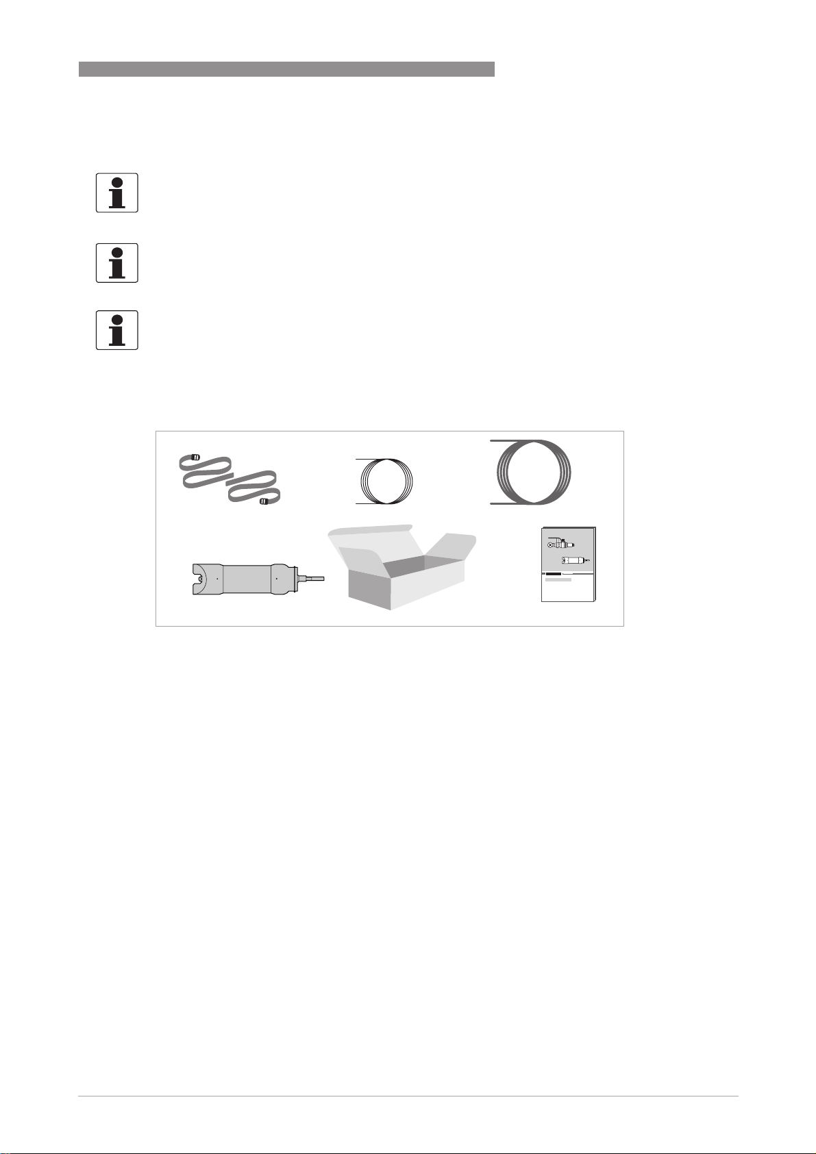
Figure 2-1: Scope of delivery OAS 2000 submersible version
1 OAS 2000 suspended solids sensor (submersible version)
2 2straps
3 10 m / 33 ft signal cable
4 10 m / 33 ft flush hose
5 Handbook
5
Optional accessories for OAS 2000 submersible version (if ordered)
• MAA 2000 insertion holder, telescopic rod for OAS/AAS 2000 (incl. telescopic rod plus rod
holder, handrail mounting bracket and sensor adapter)
• MAA 2000 side wall mounting for OAS/AAS 2000
• Signal cable extension for OPTISENS 2000 sensors (10 m / 33 ft)
• Signal cable extension for OPTISENS 2000 sensors (30 m / 98 ft)
www.krohne.com07/2010 - MA OAS 2000 R02 en
9
Page 10
2 DEVICE DESCRIPTION
2.1.2 Scope of delivery
234
OPTISENS OAS 2000
1
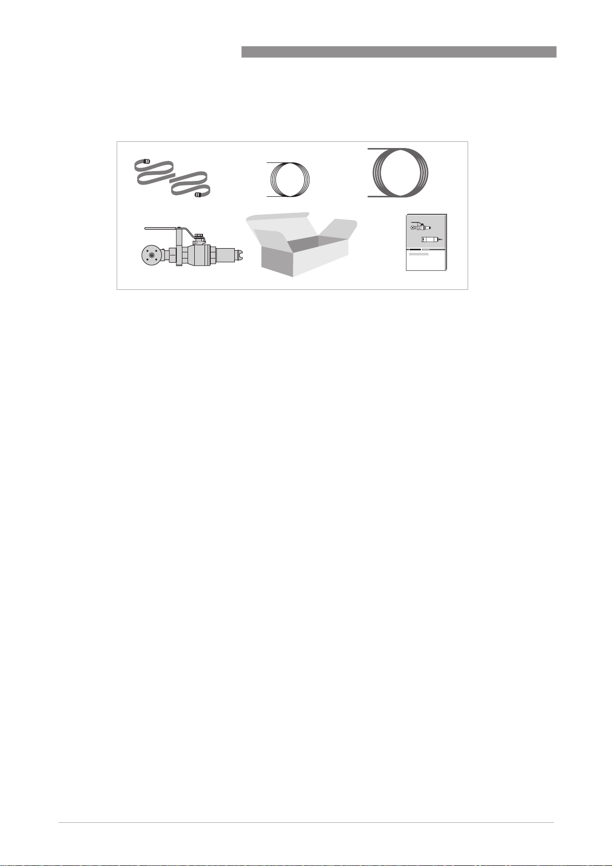
Figure 2-2: Scope of delivery OAS 2000 inline version
1 OAS 2000 suspended solids sensor (inline version), connection valve, but weld end R 1½" for pipe mounting.
Optional: OAS 2000 suspended solids sensor (inline version) without connection valve and but weld end.
2 2straps
3 10 m / 33 ft signal cable
4 10 m / 33 ft flush hose
5 Handbook
Optional accessories for OAS 2000 inline version (if ordered)
• Signal cable extension for OPTISENS 2000 Sensors (10 m / 33 ft)
• Signal cable extension for OPTISENS 2000 Sensors (30 m / 98 ft)
• OAS 2000 inline connection valve
• OAS 2000 inline but weld end R 1 ½" for pipe mounting
• OAS 2000 inline 1/12" NPT nipple
• Sealing kit for OAS 2000 inline-version: flush membrane, o-ring between valve and adapter
48 x 2 EP70, o-ring in the adapter 33.3 x 2.4 EP70, o-ring on OAS 2000 inline 29 x 2.5 EP70
2.2 Device description
The sensor is designed to measure suspended solids concentrations in liquids. Combined with
the MAC 080 converter, the sensor is used to measure suspended solids content as a function of
the ability of suspended materials to absorb and reflect NIR-light (Near Infrared). The sensor is
available in two versions, for inline mounting and for submersion.
5
10
This manual details installation procedures and operational features of the sensor. Menu
navigation and technical data for the converter can be found in the converter manual.
www.krohne.com 07/2010 - MA OAS 2000 R02 en
Page 11
OPTISENS OAS 2000
2.2.1 Design
The sensor is manufactured with 316SS (SS2343) Stainless Steel. The head of the sensor is
designed to achieve the highest self-cleaning effect, providing an exact and reliable
measurement with the least possible maintenance under critical applications. The measuring
lenses within the housing are made of glass. The electronics and optics are protected in the
rugged casing, ensuring its reliability in very demanding environments.
The sensor has a fixed, shielded 10 m / 33 ft cable used for signal transmission between the
sensor and the converter. The cable sheath is made of Hytrel and is highly resistant to
aggressive materials and fluids.
The inline version of the sensor has a M12 connector to connect a standard
OPTISENS 2000 cable to the converter.
2.3 Nameplates
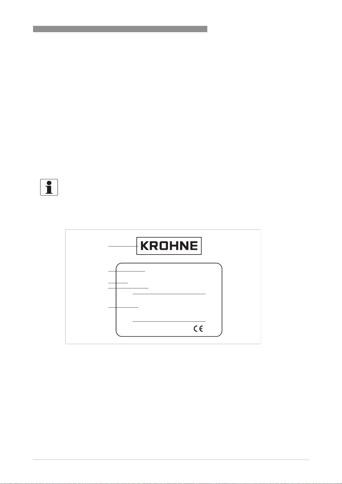
INFORMATION!
Look at the device nameplate to ensure that the device is delivered according to your order.
Check for the correct supply voltage printed on the nameplate.
DEVICE DESCRIPTION 2
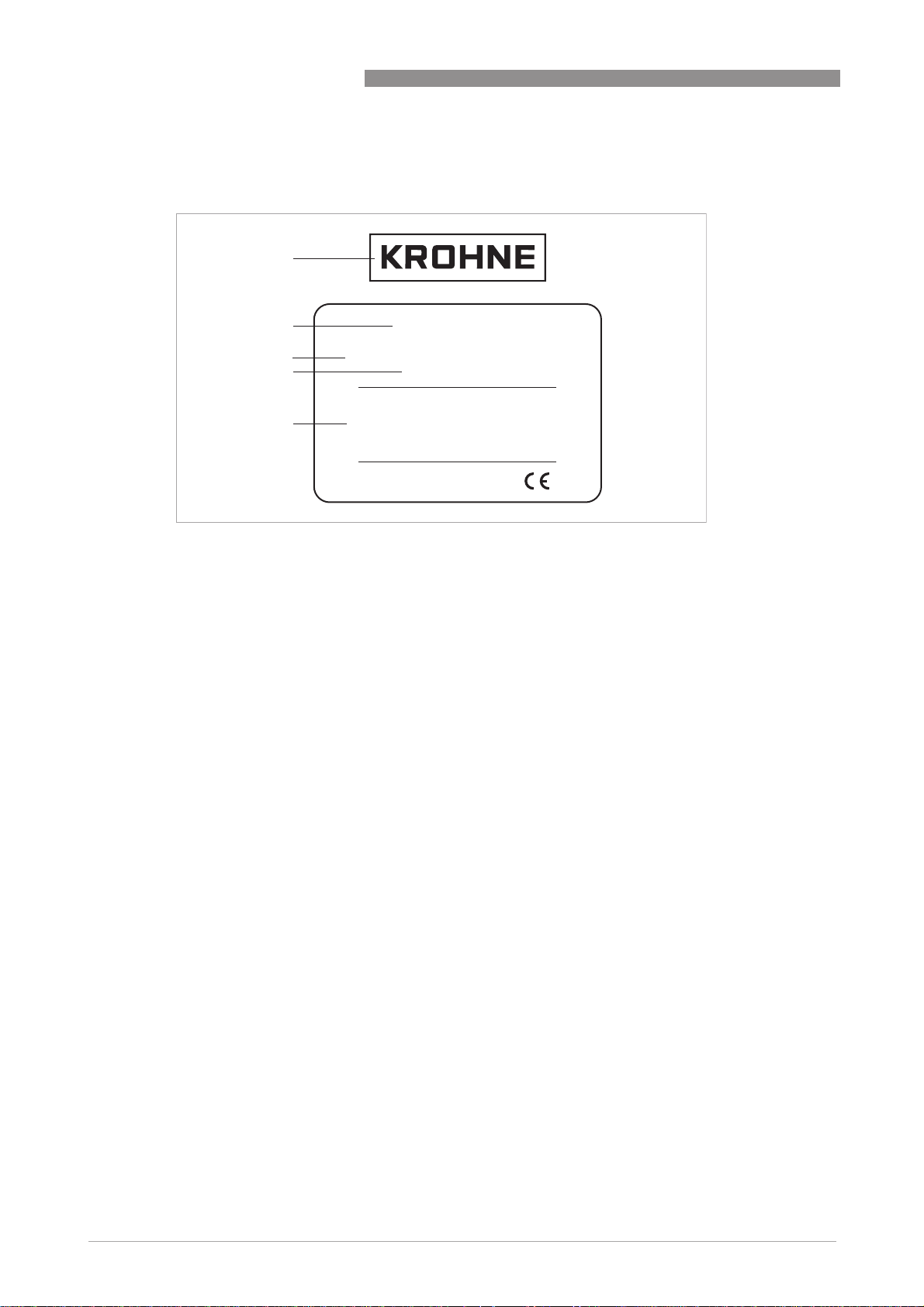
2.3.1 OPTISENS OAS 2000
1
2
3
4
5
Figure 2-3: Nameplate OPTISENS OAS 2000 submersible version
1 Manufacturer
2 Device type
3 Order code
4 Serial number
5 Sensor information
OPTISENS OAS 2000
Suspended Solids/TS Sensor
Order code: VGA R 4 A112AA4A13A0
S/N: XX XX XXX
Material: 2343/316 SS
Flush Water/Air: 6 bar
Max. depth: 10 m
Max temp.: 60C
Made in Sweden
www.krohne.com07/2010 - MA OAS 2000 R02 en
11
Page 12
2 DEVICE DESCRIPTION
2.3.2 OPTISENS OAS 2000
1
OPTISENS OAS 2000
2
3
4
5
Figure 2-4: Nameplate OPTISENS OAS 2000 inline version
1 Manufacturer
2 Device type
3 Order code
4 Serial number
5 Sensor information
Order code: VGA R 4 A2A2BA4A13A0
OPTISENS OAS 2000
Suspended Solids/TS Sensor
S/N: XX XX XXX
Material: 2343/316 SS
Flush Water/Air: 8 bar / 120 psi
Max. pressure: 6(10) bar / 90(120) psi
Max temp.: 60 ”C / 140 F
Made in Sweden
12
www.krohne.com 07/2010 - MA OAS 2000 R02 en
Page 13

OPTISENS OAS 2000
3.1 Notes on installation
INFORMATION!
Inspect the cartons carefully for damage or signs of rough handling. Report damage to the
carrier and to the local office of the manufacturer.
INFORMATION!
Check the packing list to check if you received completely all that you ordered.
INFORMATION!
Look at the device nameplate to ensure that the device is delivered according to your order.
Check for the correct supply voltage printed on the nameplate.
3.2 Storage and transport
• Store the device in a dry, dust-free location.
• Avoid continuous direct sunlight.
• The original packing is designed to protect the equipment. It has to be used if the device is
transported or sent back to the manufacturer.
INSTALLATION 3
3.3 Configuration of a measuring point
A complete measuring point consists of at least three parts:
• MAC 080 converter
• OPTISENS 2000 sensor (including cable)
• MAA 2000 sensor holder
If automatic flushing is installed, an optional solenoid valve is necessary as well.
Examples of typical measuring points are listed in the following sections.
www.krohne.com07/2010 - MA OAS 2000 R02 en
13
Page 14
3 INSTALLATION
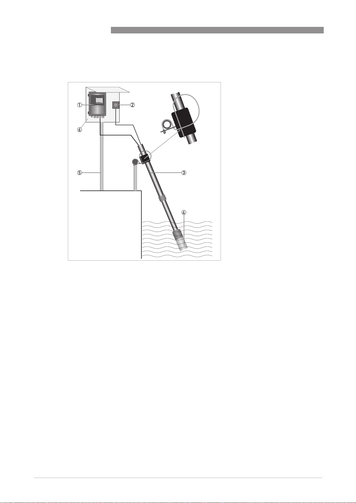
3.3.1 Single parameter measuring point
OPTISENS OAS 2000
1 Converter
2 Solenoid valve for flushing (to be ordered with converter)
3 Mounting assembly
4 Sensor incl. 10 m / 33 ft cable and flush hose
5 Mounting post
6 Mounting plate with sun shield
The figure above shows a single parameter measuring point consisting of one converter 1, one
sensor 4 with a telescopic rod immersion assembly as sensor holder 3 and one solenoid valve
2 for flushing.
The spring loaded mounting bracket for installation of the telescopic rod sensor holder on the
handrail is included in the delivery of the holder and can be used for round and square hand rails
with a maximum diameter of 50 mm / 2".
The signal cable to the sensor and the flush hose are provided with the sensor.
The mounting plate with sun shield and the mounting post are available optional.
14
www.krohne.com 07/2010 - MA OAS 2000 R02 en
Page 15
OPTISENS OAS 2000
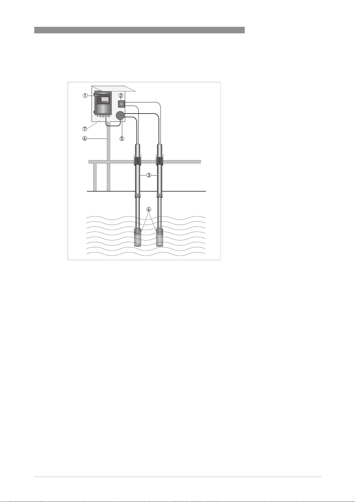
3.3.2 Two parameter measuring point
INSTALLATION 3
1 Converter
2 Solenoid valve for flushing (to be ordered with converter)
3 Mounting assembly
4 Sensor incl. 10 m / 33 ft cable and flush hose
5 Junction box for connection of up to 4 sensors (to be ordered with converter)
6 Mounting post
7 Mounting plate with sun shield
The figure above shows a two parameter measuring point consisting of one converter 1, two
sensors 4 with a telescopic rod immersion assembly as sensor holder 3 and one solenoid valve
2 for flushing.
Both sensors are flushed via one solenoid valve using an optional Y-splitter.
For connection of two sensors to the converter an optional junction box is needed.
www.krohne.com07/2010 - MA OAS 2000 R02 en
15
Page 16

3 INSTALLATION
3.3.3 Four parameter measuring point
OPTISENS OAS 2000
1 Converter
2 Solenoid valve for flushing (to be ordered with converter)
3 Mounting assembly
4 Sensor incl. 10 m / 33 ft cable and flush hose
5 Junction box for connection of up to 4 sensors (to be ordered with converter)
6 Mounting post
7 Mounting plate with sun shield
The figure above shows a four parameter measuring point consisting of one converter 1, four
sensors 4 with a telescopic rod immersion assembly as sensor holder 3 and two solenoid
valves 2 for flushing.
Two sensors each are flushed via one solenoid valve using an optional Y-splitter.
For connection of four sensors to the converter an optional junction box is needed.
16
www.krohne.com 07/2010 - MA OAS 2000 R02 en
Page 17

OPTISENS OAS 2000
3.4 Mounting of submersible version
The sensor can be mounted in two ways:
• On a telescopic fibreglass rod placed in a mounting bracket that fastens to a handrail (see
next section).
• To an adjustable slide rail holder (see next section but one).
Installation tips
• When the sensor measures in a flume, it is important to find a place where the suspended
solids concentration is representative.
• Make sure the flushing nozzle is downstream from the lenses pointing against the stream.
This will avoid disturbances of the measurement by turbulence from the nozzle. At the same
time it will produce a shield around the nozzle, due to a constant over pressure, preventing
particles from getting in.
• Adjust the rod so that the sensor is at least 30 cm / 11.8" below the liquid surface or the
lowest water level in decant applications to prevent the sensor from coming out of the liquid.
• In an aeration tank, ensure that the sensor is not directly above a diffuser head. It should be
installed on the backside of the rolling diffuser effect.
• Flushing may not be required if the tank is well agitated. To verify the need for flushing,
remove the sensor from the liquid after it has been in the liquid for several days.
• When installing in a clarifier, compressed air flushing is required due to no agitation of liquid
and to remove oil and grease film on lens. This is especially applicable in primary clarifiers.
• When using the sensor for influent applications, always install the unit after the bar screen. If
the bar screen spacing is larger than 6 mm / 0.24", then a baffle or diffuser plate should be
installed in front of the sensor to prevent rags from catching on the sensor head. On influent
applications, compressed air flushing is recommended due to the oil or grease in the liquid.
INSTALLATION 3
3.4.1 Mounting to MAA 2000 telescopic rod immersion holder
The mounting bracket of the telescopic rod is mounted to a handrail or a separate holder.
In case a handrail is not available, a mounting post with a vertical bar for sensor mounting can be
purchased from the manufacturer.
www.krohne.com07/2010 - MA OAS 2000 R02 en
17
Page 18

3 INSTALLATION
Figure 3-1: Placing the rod holder around the rod
1 Telescopic rod
2 Rod holder
OPTISENS OAS 2000
Figure 3-2: Pulling the cable/hose through the rod
1 Cable/hose
2 Telescopic rod
3 Sensor holder
4 Sensor
Figure 3-3: Inserting the rod holder into the mounting bracket
1 Telescopic rod
2 Rod holder
3 Mounting bracket
18
www.krohne.com 07/2010 - MA OAS 2000 R02 en
Page 19

OPTISENS OAS 2000
INSTALLATION 3
1 Telescopic rod
2 Sensor holder
3 Handrail with mounting bracket attached
4 Rod holder
5 Mounting bracket
CAUTION!
Do not extend the rod sections beyond the black lines. This could lead to rod damage.
INFORMATION!
°
For best measurement, the rod shall be mounted in an angle (5...30
from vertical).
www.krohne.com07/2010 - MA OAS 2000 R02 en
19
Page 20

3 INSTALLATION
Mounting to telescopic rod immersion holder
• Mount the flexible mounting bracket on an existing handrail or on a separate holder, diameter
32...50 mm / 1.3...2.0" or square 28...42 mm / 1.1...1.7". The bent lip on the mounting plate
shall be on top and faced toward the liquid or tank.
• Adjust the mounting bracket to the correct angle and tighten the nuts.
i The bracket shall be fixed to the rail and must not be able to rotate around it.
• Disassemble the rod holder and place it around the telescopic rod.
• Use the SS screws on the rod holder to tighten the rod holder to the rod.
• Pull the cable and hose through the sensor holder and rod.
• Connect the sensor to the rod with the two piece black PVC sensor holder.
• Tighten the adapter halves until snug, which will leave about 1.5 mm / 0.06" gap.
The gap is required so the water can drain from the rod.
• Adjust the length of the telescopic rod as necessary by twisting the nuts while holding the rod.
Do not extend the rod sections beyond the black lines. This could lead to rod damage.
• Insert the PVC rod holder with the telescopic rod into the mounting bracket. Make sure that
the guide tracks of the rod holder are properly seated in the bracket.
• Fasten the safety-locking clamp.
• Check that the mounting bracket is safely fixed to the rail for the spring to work the way it is
intended.
OPTISENS OAS 2000
3.4.2 Mounting to MAA 2000 slide rail immersion holder
Figure 3-4: Mounting to MAA 2000 slide rail immersion holder
1 Slide rail immersion holder
2 Sensor
3 66 mm / 2.60" clamp
4 Adjustable stop
20
www.krohne.com 07/2010 - MA OAS 2000 R02 en
Page 21

OPTISENS OAS 2000
CAUTION!
In order to avoid large air bubbles which can affect the measurement please make sure that the
slide rail immersion holder is mounted in a certain angle to the vertical position. The angle
should be slightly off from vertical position (approx. 20
Mounting to MAA 2000 slide rail immersion holder
• Mount the slide rail immersion holder to the side wall of the basin or open channel using the
two predrilled holes. The adjustable stop should be on the bottom and the two sliding clamps
above.
• Take the two sliding clamps off from the slide rail and mount them around the sensor housing.
Make sure that the clamps are placed on the two elevated ends of the sensor housing (one on
the upper part and one on the lower part, see figure above).
The two guide tracks have to line-up in one straight line to each other.
• Slide the sensor with the two clamps into the slide rail. Make sure that the guide tracks of the
two clamps are properly seated.
• Adjust the sensor position as necessary and fasten the adjustable stop.
3.5 Installation of flushing
INSTALLATION 3
°
), but not more than 90°.
The sensor is equipped with built-in flushing nozzles. The nozzles are used to direct the cleaning
medium (compressed air or water) via a flushing hose that is connected to the top of the sensor
housing. A solenoid valve that is wired to a relay in the converter controls the air or liquid (see
converter manual).
Compressed air is recommended for most applications.
CAUTION!
For the submersible sensor the highest allowed flushing pressure is 6 bar / 87 psi. When using
air, 2 bar / 29 psi is usually sufficient.
CAUTION!
For the inline sensor the highest allowed flushing pressure is 8 bar / 116 psi. Inline sensors
require a flushing pressure at least 2 bars / 29 psi above the process pressure.
INFORMATION!
Pay attention to the requirements for protection against backflow, according to the
EN 1717 standard for drinking water devices. If possible, use plant reuse water or effluent water
for cleaning.
www.krohne.com07/2010 - MA OAS 2000 R02 en
21
Page 22

3 INSTALLATION
Figure 3-5: Flushing system
1 Flushing
2 Flushing tube
INFORMATION!
In order to clean the sensor, flushing must be activated in the Settings
There are two different ways of cleaning a sensor: The sensor can either be cleaned as a master
or as a slave. Both options are described in the following instructions.
OPTISENS OAS 2000
Settings menu of the converter.
SettingsSettings
Cleaning the sensor as a master (sensor has its own relay)
• Select the sensor in the main menu by using ↑ or ↓.
• Press ^ for approximately 5 seconds to enter the sensor menu.
• Use ↑ or ↓ to select Cleaning
• In the Cleaning
Cleaning submenu, select Cleaner
CleaningCleaning
• Then specify the cleaning interval in minutes (Interval min
(Length sec
Length sec).
Length secLength sec
Cleaning and press ^.
CleaningCleaning
Cleaner and set it to Flush
CleanerCleaner
Flush.
FlushFlush
Interval min) and the flush time in seconds
Interval minInterval min
• Specify the relay to be used according to the wiring inside the converter. For example, if the
solenoid is wired to relay #1, set Relay
• For sensors configured as masters, Next time
Relay to #1
RelayRelay
#1 for flushing.
#1#1
Next time displays that the next time flush will be
Next timeNext time
activated. Pushing ^ will set it to current time and thus start cleaning.
• If needed, specify the extra freeze time in seconds (Freeze sec
Freeze sec).
Freeze secFreeze sec
Cleaning the sensor as a slave (along with another sensor)
• Select the sensor in the main menu by using ↑ or ↓.
• Press ^ for approximately five seconds to enter the sensor menu.
• Use ↑ or ↓ to select Cleaning
• The parameters Cleaner
sensor being the master.
• Set Relay
Relay to Along #1
RelayRelay
Along #1 or Along #2
Along #1Along #1
• If needed, specify the extra freeze time in seconds (Freeze sec
Cleaning and press ^.
CleaningCleaning
Cleaner, Interval min
CleanerCleaner
Interval min and Length sec
Interval minInterval min
Along #2 depending on what relay the master sensor uses.
Along #2Along #2
Length sec in the Cleaning
Length secLength sec
Freeze sec).
Freeze secFreeze sec
Cleaning submenu are set for the
CleaningCleaning
22
www.krohne.com 07/2010 - MA OAS 2000 R02 en
Page 23

OPTISENS OAS 2000
3.6 Mounting of inline version
CAUTION!
Be aware that the force may be strong when the sensor is mounted under pressure.
CAUTION!
If the following instructions cannot be fulfilled in all parts, the sensor should not be mounted or
dismounted under process pressure.
The inline sensor is mounted through a ball valve to make it possible to remove the sensor
under pressure. Make sure there is at least 260 mm / 10.2" free space to remove the sensor
from the valve. The sensor shall be mounted in a place where the process pressure is at least
1 bar. In horizontal pipes the sensor shall be mounted from the side or from below to avoid
disturbance from air bubbles.
The sensor is designed to be mounted in a right angle to the process flow. The smallest process
pipe diameter to mount the sensor is 80 mm / 3.1". The measure gap must be at least 5 mm /
0.2" from the pipe wall. If a sample outlet is used it must reach at least 20 mm / 0.8" into the
pipe.
INSTALLATION 3
Place the sensor at a location where there is no risk for it to get damaged. When the OAS 2000
inline is used outdoors, it shall be mounted with a sun and rain protective hood.
Figure 3-6: Mounting of sensor and sample outlet
1 Inline sensor with ball valve
2 Process pipe
3 Sample outlet
Dimensions [mm] Dimensions [inches]
a min. 80 mm min. 3.1"
b min. 5 mm min. 0.2"
c min. 20 mm min. 0.8"
www.krohne.com07/2010 - MA OAS 2000 R02 en
23
Page 24

3 INSTALLATION
Figure 3-7: Mounting of weld end with strip iron
1 Weld end
2 Weld
3 Process pipe
4 Stabilizing weld
OPTISENS OAS 2000
Ø [mm] Ø [inches]
a 48.5 1.91
Mounting the weld end (see previous figure)
• Open a Ø 48.5 mm / 1.91" hole in the process pipe.
• Cut the weld end to get the sensor head at least 5 mm / 0.2" from the pipe wall.
• Weld the weld end to the pipe.
• Stabilize the weld end using 3 mm / 0.1" strip iron according to the figure above.
Mounting the optional threaded nipple in a saddle
• Mount the saddle on the pipe according to the saddle manufacturer's instructions.
• Thread the nipple into the saddle.
• Use flaxen hair and joint paste. Be aware to get the correct distance from the pipe wall to the
valve.
24
www.krohne.com 07/2010 - MA OAS 2000 R02 en
Page 25

OPTISENS OAS 2000
Figure 3-8: Mounting of sensor in ball valve
1 Flush hose
2 Sensor nut
3 Adapter
4 Weld end nipple or 1½" NPT threaded nipple
5 Ball valve
6 Lockring
7 O-ring 48 x 2 mm / 1.9 x 0.1"
8 O-ring 33.3 x 2.4 mm / 1.3 x 0.1"
9 O-ring 29 x 2.5 mm / 1.1 x 0.1"
INSTALLATION 3
Mounting the ball valve (see previous figure)
• Thread the valve end on the but weld end or nipple (use sealing tape or flaxen hair and joint
paste).
INFORMATION!
Don not pull the valve end to the bottom. The valve handle plane shall have the same direction as
the pipe. If the valve is turned the wrong way, the measuring gap will not be in line with the flow,
resulting in faulty measurement.
The sensor is mounted in the valve using an adapter. The adapter serves two purposes:
1. A thread for the sensor nut to keep the sensor in place.
2. A stop for the lockring to prevent the sensor from coming loose when the sensor nut is loos-
ened.
www.krohne.com07/2010 - MA OAS 2000 R02 en
25
Page 26

3 INSTALLATION
CAUTION!
Be careful that the sensor is inserted straight. If the sensor is not straight, it can jam and so
cause damages on the transmitter or valve.
CAUTION!
If the transmitter is hard to mount and you suspect something that is stuck or the transmitter is
not mounted straight, crank out and check that everything is OK.
CAUTION!
The Sensor nut can release big forces. Do not ever loosen the nut without holding the sensor in
place at the same time.
Mounting the sensor (see previous figure)
• Make sure that the o-rings in the adapter between the sensor and the valve and on the sensor
below the sensor nut are in a faultless condition.
• Use silicon grease or soup to grease the o-rings before mounting the adapter.
• If the adapter is separated from the sensor, check and grease the o-ring inside the adapter.
Then push the adapter over the sensor head having the smaller thread towards the sensor
housing.
• Mount the lockring on the sensor head.
• Thread the adapter into the valve.
i The sensor is now fixed to the valve.
OPTISENS OAS 2000
• When the adapter is tightened, open the valve.
• Push the sensor in place. If the process pressure is high, considerable force may be needed to
push the sensor in place.
• Screw the sensor nut in place, but do not tighten it yet.
• Align the sensor in parallel with the process flow.
• Tighten the sensor nut.
i The sensor is mounted.
26
www.krohne.com 07/2010 - MA OAS 2000 R02 en
Page 27

OPTISENS OAS 2000
4.1 Safety instructions
DANGER!
All work on the electrical connections may only be carried out with the power disconnected. Take
note of the voltage data on the nameplate!
DANGER!
Observe the national regulations for electrical installations!
DANGER!
For devices used in hazardous areas, additional safety notes apply; please refer to the Ex
documentation.
WARNING!
Observe without fail the local occupational health and safety regulations. Any work done on the
electrical components of the measuring device may only be carried out by properly trained
specialists.
ELECTRICAL CONNECTIONS 4
INFORMATION!
Look at the device nameplate to ensure that the device is delivered according to your order.
Check for the correct supply voltage printed on the nameplate.
4.2 Cable connections
The sensor is equipped with a fixed 10 m / 33 ft cable, which has a M12 connector attached.
Connect the sensor to the converter using the M12 connector. In the event that two or more
sensors should be connected to the same converter, use the optional junction box.
Power requirements:
• The sensor requires 24 VDC power, which is supplied from the converter via the sensor cable.
• The maximum current during operation is 45 mA.
www.krohne.com07/2010 - MA OAS 2000 R02 en
27
Page 28

5 OPERATION
5.1 Sensor display
By simultaneously pressing ↓ and ^ you alter between the converter main menu and the sensor
information display for the selected sensor. The sensor information display shows the sensor's
calibration curve.
5.2 Menu for OAS 2000 sensor
Use ↑ or ↓ to select the sensor in the main display. The menu for the selected sensor is accessed
by pressing ^ for five seconds. If the selected sensor is not active (the text No transmitter
shown) a warning is displayed that asks you to make another choice in order to show the sensor
menu.
Menu "Settings"
Submenu Description
Tag
Tag Name of the sensor shown in the main display (10 characters).
TagTag
I-Time
I-Time Integration time or dampening (can be set up to 999 seconds).
I-TimeI-Time
Unit
Unit "%", "ppm", "g/l", "mg/", NTU, FNU
UnitUnit
Decimals
Decimals "Std" or "Extra". Number of decimals for the reading.
DecimalsDecimals
Analog
Analog "None" , "Out1", "Out2", "Out3", "Out4", "Out1+2" or "Out3+4". Pick
AnalogAnalog
Second
Second "Temp" or "=Prim". If two analog outputs are chosen above, the first
SecondSecond
OPTISENS OAS 2000
No transmitter is
No transmitterNo transmitter
which analog output(s) should be used with sensor.
will always give the primary value according to the sensors selected
scale. The second will either give the temperature scaled 0...100°C/
32...212°F, or the same signal as the first channel. The temperature
is additional information, not a precision measurement.
Menu "Calibrate"
Submenu Description
Adjust
Adjust "No", "Store" or "Lab". Stores the reading of the meter when a
AdjustAdjust
Take sample
Take sample "No", "Zero", "1", "2", "3", "4", "5". Sensor stores current MS (light)
Take sampleTake sample
Con
Con Current concentration (same as shown in the main menu).
ConCon
Sample 1
Sample 1 Lab test (suspended solids value for Sample 1)
Sample 1Sample 1
Sample 2
Sample 2 Lab test (suspended solids value for Sample 2)
Sample 2Sample 2
Sample 3
Sample 3 Lab test (suspended solids value for Sample 3)
Sample 3Sample 3
Sample 4
Sample 4 Lab test (suspended solids value for Sample 4)
Sample 4Sample 4
Sample 5
Sample 5 Lab test (suspended solids value for Sample 5)
Sample 5Sample 5
sample is taken and can then automatically adjust the sample value
when the sample analysed by lab is different to the reading.
value in memory and you enter a lab solids value below to complete
calibration.
28
www.krohne.com 07/2010 - MA OAS 2000 R02 en
Page 29

OPTISENS OAS 2000
Menu "Cleaning"
Submenu Description
Press ^ to go to the cleaning program
Cleaner
Cleaner "None", "Flush" or "Brush". Do not select "Brush" since this does not
CleanerCleaner
Interval min
Interval min 0...999 minutes, time between cleaning cycles (only for master).
Interval minInterval min
Length sec
Length sec 0...999 seconds, duration of flushing cycle (only for master).
Length secLength sec
Freeze sec
Freeze sec 0...999 seconds, extra freeze time of output signal after a
Freeze secFreeze sec
Relay
Relay "-", "1", "2", "Along 1" or "Along 2". Select relay to operate solenoid
RelayRelay
Next time
Next time The next scheduled cleaning time. Pushing ^ on this line will set the
Next timeNext time
Menu "Scale / Alarm"
OPERATION 5
exist for this sensor (only for master).
flushing cycle.
for flush cycle if this sensor is a master with its own relay, or relay
used by master if this sensor is a slave. These are the same relays
used for Alarm relay
time to current time and start a cleaning cycle. This could be used to
test the flush cycle (only for master).
Alarm relay below.
Alarm relayAlarm relay
Submenu Description
Max
Max 0...99.9 % or 0...99999.9 ppm, mg/l or g/l (units selected in the menu
MaxMax
Min
Min 0...99.9 % or 0...99999.9 ppm, mg/l or g/l (units selected in the menu
MinMin
Hi-Alarm
Hi-Alarm 0...99.9 % or 0...99999.9 ppm, mg/l or g/l (units selected in the menu
Hi-AlarmHi-Alarm
Low-Alarm
Low-Alarm 0...99.9 % or 0...99999.9 ppm, mg/l or g/l (units selected in the menu
Low-AlarmLow-Alarm
Alarm Relay
Alarm Relay "-" "1", "2", or "1 and 2". Check that the relay is not being used for
Alarm RelayAlarm Relay
"Settings"
"Settings"), equal to 20 mA output signal.
"Settings""Settings"
"Settings"
"Settings"), equal to 4 mA output signal.
"Settings""Settings"
"Settings"
"Settings"), the value zero inactivates the alarm.
"Settings""Settings"
"Settings"
"Settings"), the value zero inactivates the alarm.
"Settings""Settings"
cleaning.
www.krohne.com07/2010 - MA OAS 2000 R02 en
29
Page 30

5 OPERATION
Menu "System"
Submenu Description
Type
Type Type of sensor (read only)
TypeType
Serial
Serial Serial number of the sensor (read only)
Serial Serial
SoftW
SoftW Software version of the sensor (read only)
SoftWSoftW
Temp
Temp Sensor temperature (read only)
TempTemp
MaxTemp
MaxTemp The highest temperature the sensor has been exposed to (read only)
MaxTempMaxTemp
Samples
Samples Press ^ to view SA values and suspended solids values.
SamplesSamples
SA 0 SA value for zero sample
SA 1 SA value for sample 1
Cons 1 Lab test (suspended solids value for sample 1)
... SA and Cons repeated for samples 2 to 5
Info
Info Press ^ to go to menu "Info"
InfoInfo
MS Linearised light signal, which are SA values in calibration chart.
Con Unit value in %, ppm, mg/l or g/l after MS value has been converted to
SA 0 SA value for zero sample
SA 1 SA value for sample 1
Cons 1 Lab test (suspended solids value for sample 1)
Ch1a Raw value for channel 1
Ch1 Raw value for channel 1, compensated for changed intensity.
Ch2 Raw value for channel 2
Intensity Currently used intensity
Zero Int Intensity for clear water, set during zero calibration.
I-offset Intensity offset, set during zero calibration.
Samp/s Number of samples per second
Service
Service Not accessible for users
ServiceService
OPTISENS OAS 2000
"Info" (read only). This menu is for KROHNE
internal use, it may change without notice.
units due to sample values. This is displayed on main screen.
"Info""Info"
5.3 Calibration
The MAC 080 has a self-optimizing calibration algorithm able to handle several calibration
points in order to give maximum measuring precision in difficult applications. However, a single
point calibration is usually preferred.
After a calibration has been carried out, make it a habit to look at the calibration curve in the
sensor information screen to make sure it represents a smooth line without any sharp bends.
• Leave the instrument turned on for about 30 minutes prior to calibration so that the sensor
and electronics can stabilize.
• Please check that the correct unit is selected for the application. In the sensor menu, select
Settings > Unit
Settings > Unit.
Settings > UnitSettings > Unit
30
www.krohne.com 07/2010 - MA OAS 2000 R02 en
Page 31

OPTISENS OAS 2000
5.3.1 Calibration Points
To calculate the consistency or concentration out of the loss of light the sensor uses a calibration
curve. The curve is built up of the zero calibration point and at least one calibration point.
Each point has a sample value and a consistency value. To be used a point needs both values.
The sample value is set by Calibrate > Take sample
value is manually entered in the same menu after having analysed the actual consistency at the
time the sample was taken.
A calibration point can be disabled by setting the consistency value to zero. In most applications
one calibration point in addition to the zero sample is the best solution, adding more samples
then just confuses the measurement. Only in the following cases a multipoint calibration is
needed:
1. The measurement turns out to be non linear.
2. The sensor needs to be very accurate at widely separated consistencies.
The zero calibration defines the zero point used as a reference for all other calibration points.
The other points define the relation between loss of light and real consistency.
OPERATION 5
Calibrate > Take sample in the calibration menu. The consistency
Calibrate > Take sampleCalibrate > Take sample
Figure 5-1: Example of a calibration curve
1 Loss of light
2 Consistency
5.3.2 Negative values
The sensor continuously compares the loss of light to its calibrated points. If, for some reason,
the loss of light is less than when the sensor was zero-calibrated, the sensor shows a negative
consistency. This is not a fault, it just indicates the liquid in the sensor absorbs less light than the
liquid used as zero reference. Please contact the manufacturer if this is a problem for you.
1
0
2
www.krohne.com07/2010 - MA OAS 2000 R02 en
31
Page 32

5 OPERATION
5.3.3 Calibration screen
The sensor information menu is the calibration curve screen. To change between the main menu
and the calibration screen, press ↓ and ^ simultaneously.
The converter uses at least a zero sample and one sample (single point calibration). Up to five
samples may be used to create a calibration curve (multipoint calibration).
INFORMATION!
The sample number itself does not change, only the order in which the samples are used.
The calibration menu displays sample values placed in a graph.
OPTISENS OAS 2000
Figure 5-2: Calibration screen
1 Single point calibration
2 Multi point calibration
• The X-scale displays consistency/suspended solids, where min
on the left and max
max value (20 mA output) is shown on the right.
maxmax
min value (4 mA output) is shown
minmin
• The Y-scale displays the light loss due to solids from the sensor light source. The converter
uses the light loss values to calculate which measuring signal corresponds to minconsistency/suspended solids and max-consistency/suspended solids.
• The actual measuring value is indicated with an arrow that moves up and down to the left of
the Y-scale axis.
• Samples that are not within the chosen scale of the active sensor are not displayed on the
calibration screen. However, these samples are still used in the calculations. If you want to
see a point outside the sensor scale, then you may temporarily change the scale in the sensor
menu Scale/Alarm.
Scale/Alarm.
Scale/Alarm.Scale/Alarm.
If the sample values are switched or the lab result is incorrectly performed, then the calibration
curve will be incorrect. Such a mistake is easy to discover on the calibration screen since a part
of the calibration curve will go in the wrong direction. Different measuring values should never
correspond to the same consistency/suspended solids.
32
www.krohne.com 07/2010 - MA OAS 2000 R02 en
Page 33

OPTISENS OAS 2000
Figure 5-3: Incorrect calibration
In the above figure the curve goes backwards because two samples have been exchanged when
entering the lab results. A higher Y-value must have a higher X-value. The curve must continue
upwards and to the right.
5.3.4 Automatic adjustment of the calibration
OPERATION 5
The function Adjust
easy way using an offset value. When a sample is taken to be analysed by lab, the converter
stores the reading. When the sample has been analysed, the result is keyed in to the converter.
The converter will compare it to the stored reading and calculate a new setting for the sample
value.
Automatic adjustment (offset) only works for single point calibrations and is primarily intended
as an easy way to get started with a new sensor. Once the automatic adjustment is done and the
sensor gives a sensible reading, we recommend using a statistical adjustment to get a higher
accuracy over time (see next section).
Adjust in the Calibrate
AdjustAdjust
Calibrate menu is used to automatically adjust the calibration in an
CalibrateCalibrate
CAUTION!
Even though the sensors have daylight-filters, they are sensitive to the infrared parts of the
sunlight. Always cover the sensor and the bucket before calibration.
Running an automatic adjustment
• Fill a bucket with a sample of the liquid you intend to measure.
• Submerge the sensor into the liquid.
• Select the sensor to be calibrated in the menu by using ↑ or ↓.
• Press ^ for approximately 5 seconds to enter the sensor menu.
• Select Calibrate > Adjust
• Select Take sample
• Take the bucket to the lab for analysis. Note the concentration of the sample determined at
• Select Calibrate > Adjust
• Press ^.
• Press ^ to use the stored reading or ↑ to key in a value.
• Key in the result of the lab analysis, then press ^.
Calibrate > Adjust and then Store
Calibrate > AdjustCalibrate > Adjust
Take sample and stir the sample in the bucket until the measuring is finished.
Take sampleTake sample
the lab.
Calibrate > Adjust and then Lab
Calibrate > AdjustCalibrate > Adjust
Store using ↑ and ↓.
StoreStore
Lab using ↑ and ↓.
LabLab
i MAC 080 will show the current value and the suggested new value for "Sample 1".
• Acknowledge the change by pressing ^ or abort using ↑ or ↓.
www.krohne.com07/2010 - MA OAS 2000 R02 en
33
Page 34
5 OPERATION
5.3.5 Statistic adjustment
Statistic adjustment of the lab sample value is a much better way to good measurement than
frequent calibration. This is done comparing the lab results with the instrument reading over
time. If a systematic discrepancy is detected, change accordingly the value of the lab sample
used in the converter by using the Adjust
If, for example, several lab results for a period of time in average show 5 % more than the
instrument, the sample value in the converter shall be increased by 5% of its value. E.g. if the
sample value is 10000 mg/l, it shall be changed to 10500 mg/l.
Using the statistic method will increase the accuracy and reliability of the measurement as time
passes while new calibrations will start from scratch. An Excel sheet to help doing statistical
adjustment of the calibration can be obtained from the manufacturer.
Running a statistic adjustment
• Select the sensor to be calibrated in the menu by using ↑ or ↓.
• Press ^ for approximately 5 seconds to enter the sensor menu.
• Select Calibrate > Adjust
• Press ^.
• Press ↑ to key in a value.
• Key in the result of the statistical calculation, then press ^.
i The converter will show current and suggested new value for "Sample 1".
Calibrate > Adjust and then Lab
Calibrate > AdjustCalibrate > Adjust
Adjust function in the calibration menu.
AdjustAdjust
Lab using ↑ and ↓.
LabLab
OPTISENS OAS 2000
• Acknowledge the change by pressing ^ or abort using ↑ or ↓.
5.3.6 Zero calibration
CAUTION!
Even though the sensors have daylight-filters, they are sensitive to the infrared parts of the
sunlight. Always cover the sensor and the bucket before calibration.
The sensor is zero-calibrated at the factory and does not often need to be zero-calibrated.
Before doing a zero calibration, always check that it is really needed. Make sure the lenses are
clean, and use clean de-aerated water to check the sensor reading. Tap water is best de-aerated
by leaving the water in an open bucket for at least two hours.
34
www.krohne.com 07/2010 - MA OAS 2000 R02 en
Page 35

OPTISENS OAS 2000
Running a zero calibration
• Remove the sensor from the process and clean the sensor head.
• Dip the sensor in a bucket of clean water.
• Select the sensor to be calibrated in the menu by using ↑ or ↓.
• Press ^ for approximately 5 seconds to enter the sensor menu.
• Select Calibrate > Take sample
• Select Zero
• To acknowledge that you really want to change the zero calibration, select Yes
^.
i The converter will ask you to put the sensor in clean water.
• Submerge the sensor head into the clean water and cover it from direct sunlight.
• Press ^.
• Wait for the zero calibration to finish. It will take approximately 30 seconds before the unit
returns to the menu.
INFORMATION!
Detailed procedures for navigating the converter software can be found in the converter manual.
Calibrate > Take sample and then press ^.
Calibrate > Take sampleCalibrate > Take sample
Zero by using ↑ or ↓ and then press ^.
ZeroZero
OPERATION 5
Yes and then press
YesYes
5.3.7 Calibration with samples
CAUTION!
Even though the sensors have daylight-filters, they are sensitive to the infrared parts of the
sunlight. Always cover the sensor and the bucket before calibration.
Calibration with sample in a bucket
• Fill a bucket with a sample of the liquid you intend to measure.
• Submerge the sensor into the liquid.
• Select the sensor to be calibrated in the menu by using ↑ or ↓.
• Press ^ for approximately five seconds to enter the sensor menu.
• Select Calibrate > Take sample
• Press ^ and stir the sample in the bucket until the calibration is finished. It will take
• Take the bucket to the lab for analysis. Note the concentration of the sample determined at
• Enter sample #1 concentration by selecting Calibrate > Sample #1
• Press ^.
• Use ↑ and ↓ to change the values and ^ to go to the next digit. Some special applications may
Calibrate > Take sample and then #1
Calibrate > Take sampleCalibrate > Take sample
approximately 30 seconds.
the lab.
need additional sample points. Do not enter samples that are identical in concentration or
less than 10% from initial values.
#1 using ↑ and ↓.
#1#1
Calibrate > Sample #1 in the calibration menu.
Calibrate > Sample #1Calibrate > Sample #1
www.krohne.com07/2010 - MA OAS 2000 R02 en
35
Page 36

5 OPERATION
Calibration of submersible sensor in a basin or channel
• Calibration can be done without the use of a bucket. Make sure that the sensor is at least
30 cm / 11.8" below the lowest liquid level.
• Follow the steps 3 to 5 of the above procedure "Calibration with a sample bucket".
• While the OAS 2000 is calibrating, grab a sample of the liquid with a dip bucket. Make sure to
grab a sufficiently large sample volume for low solids applications.
• Take the sample to the lab for analysis. Note the concentration of the sample determined at
the lab.
• Follow the steps 8 to 10 of the above procedure "Calibration with a sample bucket".
Calibration of inline sensor in a pipe
• Inline sensors are easiest calibrated if the pipe has a sample outlet.
• Follow the steps 3 to 5 of the above procedure "Calibration with a sample bucket".
• While the OAS 2000 is calibrating, open the sample valve and fill a bucket with process liquid.
• Take the sample to the lab for analysis. Note the concentration of the sample determined at
the lab.
• Follow the steps 8 to 10 of the above procedure "Calibration with a sample bucket".
5.4 Scaling
OPTISENS OAS 2000
The menu Scale / Alarm
Scale / Alarm (see converter manual) allows the user to set the high and low
Scale / AlarmScale / Alarm
boundaries for a 4...20 mA output signal. In addition, this menu allows the user to set high and
low alarm values to switch a relay when solids have reached critical points.
Max
Max Sets the 20 mA point output.
MaxMax
Min
Min Sets the 4 mA point output (may be negative for special applications).
MinMin
Hi-Alarm
Hi-Alarm Sets the high alarm set point (the value zero inactivates the alarm).
Hi-AlarmHi-Alarm
Low-Alarm
Low-Alarm Sets the low alarm set point (the value zero inactivates the alarm).
Low-AlarmLow-Alarm
36
www.krohne.com 07/2010 - MA OAS 2000 R02 en
Page 37

OPTISENS OAS 2000
6.1 Cleaning the flushing nozzle
If the flushing nozzle becomes plugged, it can usually be cleaned by backflushing it with clean
water.
Cleaning the flushing nozzle on submersible sensors
• Before attempting to backflush, close the valve of the flush water source.
• Disconnect the sensor flushing hose from the solenoid valve.
• Place a 12 mm / 0.47" hose over the flush nozzle and carefully open the water valve.
i The pressure should clear the line of solids. If backflushing does not work initially, try
cleaning the three flushing nozzles with a needle. Try backflushing the nozzles again as
described above until clean water comes out at the solenoid valve end of the hose.
INFORMATION!
The nozzle of an inline sensor usually does not need to be cleaned. The nozzle works as a check
valve to avoid that process liquid is pressed up the flushing hose. It consists of a rubber
membrane held in place by a steel bracket.
SERVICE 6
Plugging the nozzle if flushing is not used
• Plug the nozzle by removing the membrane and the steel bracket, which is attached with two
screws to the sensor head.
• Fit a spotfaced M5x8 screw with soft thread retainer in the hole.
6.2 Spare parts availability
The manufacturer adheres to the basic principle that functionally adequate spare parts for each
device or each important accessory part will be kept available for a period of 3 years after
delivery of the last production run for the device.
This regulation only applies to spare parts which are under normal operating conditions subjects
to wear and tear.
6.3 Spare parts and accessories
Order number Designation
XGA S 06010 OAS 2000 inline connection valve
XGA S 06020 OAS 2000 inline but weld end R 1½"
XGA S 06030 OAS 2000 inline 1/12" NPT nipple
XGA S 06040 Sealing kit for OAS 2000 inline version
XGA W 08010 Signal cable extension for OPTISENS 2000 sensor (10 m / 33 ft)
XGA W 08020 Signal cable extension for OPTISENS 2000 sensor (30 m / 98.4 ft)
www.krohne.com07/2010 - MA OAS 2000 R02 en
37
Page 38

6 SERVICE
6.4 Availability of services
The manufacturer offers a range of services to support the customer after expiration of the
warranty. These include repair, technical support and training.
INFORMATION!
For more precise information, please contact your local representative.
6.5 Returning the device to the manufacturer
6.5.1 General information
This device has been carefully manufactured and tested. If installed and operated in accordance
with these operating instructions, it will rarely present any problems.
CAUTION!
Should you nevertheless need to return a device for inspection or repair, please pay strict
attention to the following points:
•
Due to statutory regulations on environmental protection and safeguarding the health and
safety of our personnel, manufacturer may only handle, test and repair returned devices that
have been in contact with products without risk to personnel and environment.
•
This means that the manufacturer can only service this device if it is accompanied by the
following certificate (see next section) confirming that the device is safe to handle.
OPTISENS OAS 2000
CAUTION!
If the device has been operated with toxic, caustic, flammable or water-endangering products,
you are kindly requested:
•
to check and ensure, if necessary by rinsing or neutralizing, that all cavities are free from
such dangerous substances,
•
to enclose a certificate with the device confirming that is safe to handle and stating the
product used.
38
www.krohne.com 07/2010 - MA OAS 2000 R02 en
Page 39

OPTISENS OAS 2000
6.5.2 Form (for copying) to accompany a returned device
Company: Address:
Department: Name:
Tel. no.: Fax no.:
Manufacturer's order no. or serial no.:
The device has been operated with the following medium:
SERVICE 6
This medium is: water-hazardous
toxic
caustic
flammable
We checked that all cavities in the device are free from such
substances.
We have flushed out and neutralized all cavities in the
device.
We hereby confirm that there is no risk to persons or the environment through any residual media
contained in the device when it is returned.
Date: Signature:
Stamp:
6.6 Disposal
CAUTION!
Disposal must be carried out in accordance with legislation applicable in your country.
www.krohne.com07/2010 - MA OAS 2000 R02 en
39
Page 40

7 TECHNICAL DATA
7.1 Measuring principle
The sensor measures transmitted light through the liquid. The measuring principle is based on
the suspended particles ability to absorb and reflect NIR (Near Infrared) light. The light source is
a light emitting diode that pulses and emits monochromatic light with a wavelength of 880 nm.
The detected measuring signal is inversely logarithmical proportional to the concentration of
suspended solids. Signal treatment or linearisation is done within the converter.
In addition, the temperature is measured to be used for temperature compensation of the
measured value. It can be read in the converter and used as secondary value when a sensor is
configured to use both analog outputs.
INFORMATION!
The built-in temperature measurement is not a precision measurement, but shall be seen as an
indication.
OPTISENS OAS 2000
1
4
Figure 7-1: Cross-section of measuring gap
1 Measuring gap
2 Light source (NIR-LED)
3 Monochromatic light beam
4 Detector
3
2
40
www.krohne.com 07/2010 - MA OAS 2000 R02 en
Page 41

OPTISENS OAS 2000
7.2 Technical data
INFORMATION!
•
The following data is provided for general applications. If you require data that is more
relevant to your specific application, please contact us or your local representative.
•
Additional information (certificates, special tools, software,...) and complete product
documentation can be downloaded free of charge from the website (Download Center).
Measuring system
Measuring principle Transmitted light absorption principle, pulsed NIR 880 nm, with
Application range Continuous measurement of
Measured value Suspended solids concentration
TECHNICAL DATA 7
Submersible version Inline version
reference measurement, temperature-compensated.
Reflection and absorption of light on suspended solids and sludge
particles. The light passes the measured particles between the
emitter and the detector in a straight line.
suspended solids in waste water
and sludge (e.g. in aeration
basins).
Continuous measurement of
suspended solids in pump lines
for waste water and sludge (e.g.
in pump lines for return sludge).
Design
Modular construction
A typical measuring system consists of:
• MAC 080 multiparameter converter
• 1 (or up to 4) OPTISENS 2000 sensors
• Solenoid valves to control spray cleaning
Assemblies for submersion or
side wall installation.
Measuring range 0...20000 mg/l (ppm),
min. 0...100 mg/l (depending on
the sludge type)
Flushing Flushing using clean water or compressed air.
Pressure: 6 bar / 87 psi Pressure: 2 bar / 29 psi above
Solenoid valve: available in 220 V and 117 V versions, up to 2 sensors
can be operated on a single valve.
Flush hose: ¼" external diameter, PE, standard length: 10 m / 32.8 ft
Ball valve assembly for inline
installation.
0...5% suspended solids,
min. 0...100 mg/l (depending on
the sludge type)
process pressure, max. 10 bar /
145 psi
www.krohne.com07/2010 - MA OAS 2000 R02 en
41
Page 42

7 TECHNICAL DATA
Measuring accuracy
Reference conditions Medium: water
Maximum measuring error Typical ±2% of selected range, max. ±5% of selected range.
Display resolution
(in combination with MAC 080)
Calibration Pre-calibrated in the factory, calibration on site: software-supported
Operating conditions
Temperature Process temperature = ambient temperature
Process pressure Ambient Max. 6 bar / 87 psi with automatic
Max. immersion depth 10 m / 32.8 ft N/A
Protection category IP68 (Nema 6)
OPTISENS OAS 2000
Temperature: +25°C / +77°F
Pressure: 1 barg / 14.5 psig
Temperature: ±0.5°C/ 0.5°F
1 mg/l, extended mode: 0.1 mg/l
Temperature: 0.1°C/ 0.1°F
single or multipoint calibration using reference samples.
0…+60°C/ 32…140°F
cleaning
Max. 10 bar / 145 psi without
automatic cleaning (special
version)
Installation conditions
AAS 2000 + MAA 2000 fibreglass
telescopic rod for submersible
installations
AAS 2000 + MAA 2000 slide rail
mounting for side wall
installations
OAS 2000 inline version N/A Pipe installation using a butt
Dimensions and weights For detailed information see chapter "Dimensions and weights".
Process connection Open basins and channels 1½"ballvalve for inline
Installation on the handrail with
up to 4 m length-adjustable,
oscillating fibreglass assembly.
Handrail mounting for:
• Round handrails:
d = 32...50 mm / 1.3…2"
• Square cross-sections:
28...42 mm / 1.1…1.7"
Installation on side walls of
channels and basins using slide
rails for simple sensor removal.
N/A
N/A
weld end for holes of 48.5 mm /
1.9" diameter (standard scope of
delivery) or with an optional
1½" NPT nipple, on which a ball
valve is installed to fit the sensor.
Min. pipe diameter: 80 mm / 3.1".
installation
42
www.krohne.com 07/2010 - MA OAS 2000 R02 en
Page 43

OPTISENS OAS 2000
Materials
Enclosure 316 SS
NIR diode GAS diode, 880 nm wavelength, pulsed
Connection cable to converter Insulation: Hytrel (5-pin M12 connector, fixed cable, shielded, 10 m /
Flush hose PE
Approvals and certifications
CE sign This device fulfils the statutory requirements of the EC directives.
Electromagnetic compatibility Interference emission to EN 61000-6-4:2001; immunity to EN 61000-
Low voltage directive Safety requirements for electrical equipment for measurement,
7.3 Dimensions and weight
TECHNICAL DATA 7
32.8 ft)
The manufacturer certifies successful testing of the product by
applying the CE mark.
6-2:2001.
control and laboratory use in accordance with EN 61010-1:2001.
Figure 7-2: Submersible version
Dimensions
[mm]
Dimensions
[inches]
Weight
[kg] [lbs]
a Ø66 Ø2.6 1.6 3.5
b 20 0.8
c 227 8.9
d 255 10.0
www.krohne.com07/2010 - MA OAS 2000 R02 en
43
Page 44

7 TECHNICAL DATA
3
OPTISENS OAS 2000
1
2
Figure 7-3: In-line version
1 1½" NPT
2 Welding end
3 Min. 283 mm / 11.1" (de)installation spacing
Dimension
[mm]
Dimension
[inches]
Weight
[kg] [lbs]
a 368 14.5 4.6 10.1
44
www.krohne.com 07/2010 - MA OAS 2000 R02 en
Page 45

OPTISENS OAS 2000
8.1 Setup information form
This form can be used to document the setup of the sensor.
Sensor type:
Sensor type:
Sensor type:Sensor type:
Position / Tag:
Position / Tag:
Position / Tag:Position / Tag:
In the System
System submenu of the sensor menu the following information can be collected:
SystemSystem
Serial:
Serial:
Serial:Serial:
SoftW:
SoftW:
SoftW:SoftW:
In the Settings
Settings submenu of the sensor menu the following parameters can be set:
SettingsSettings
I-time:
I-time:
I-time:I-time:
Unit:
Unit:
Unit:Unit:
Analog:
Analog:
Analog:Analog:
Second:
Second:
Second:Second:
In the Cleaning
Cleaning submenu of the sensor menu the following parameters can be set:
CleaningCleaning
Cleaner:
Cleaner:
Cleaner:Cleaner:
Cleaning interval:
Cleaning interval:
Cleaning interval:Cleaning interval:
Cleaning length:
Cleaning length:
Cleaning length:Cleaning length:
Cleaning freeze:
Cleaning freeze:
Cleaning freeze:Cleaning freeze:
Cleaning relay:
Cleaning relay:
Cleaning relay:Cleaning relay:
In the Scale / Alarm
Scale / Alarm submenu of the sensor menu the following parameters can be set:
Scale / AlarmScale / Alarm
Max:
Max:
Max:Max:
Min:
Min:
Min:Min:
High alarm:
High alarm:
High alarm:High alarm:
Low alarm:
Low alarm:
Low alarm:Low alarm:
Alarm relay:
Alarm relay:
Alarm relay:Alarm relay:
Leave the menu by pressing ↑ and ^ simultaneously.
APPENDIX 8
www.krohne.com07/2010 - MA OAS 2000 R02 en
45
Page 46

8 APPENDIX
8.2 Support information form
Company:
Company: Name:
Company:Company:
Phone:
Phone: E-mail:
Phone:Phone:
Sensor
Sensor
Sensor Sensor
type:
type:
type:type:
First go to the converter menu by pressing ↑ and ^ simultaneously for five seconds. Then select System
and press ^. Write down the following information.
Version:
Version:
Version:Version:
Serial:
Serial:
Serial:Serial:
Box temp:
Box temp:
Box temp:Box temp:
Leave the converter menu by pressing ↑ and ^ simultaneously. Use ↑ and ↓ to select the sensor in the
main display. Go to the sensor menu by pressing ^ for 5 seconds. Then select System
down the following information.
Type:
Type: SoftW:
Type:Type:
Serial:
Serial: Temp:
Serial:Serial:
Select System > Samples
System > Samples and press ^. Write down the following information.
System > SamplesSystem > Samples
SA 0:
SA 0:
SA 0:SA 0:
SA 1:
SA 1: Cons 1:
SA 1:SA 1:
SA 2:
SA 2: Cons 2:
SA 2:SA 2:
SA 3:
SA 3: Cons 3:
SA 3:SA 3:
SA 4:
SA 4: Cons 4:
SA 4:SA 4:
SA 5:
SA 5: Cons 5:
SA 5:SA 5:
Select System > Info
System > Info and press ^. Write down the following information.
System > InfoSystem > Info
MS:
MS: Con:
MS:MS:
SA0:
SA0: SA1:
SA0:SA0:
Cons 1:
Cons 1: Ch1a:
Cons 1:Cons 1:
Ch1:
Ch1: Intensity:
Ch1:Ch1:
Zero Int:
Zero Int: I-offset:
Zero Int:Zero Int:
Leave the menu by pressing ↑ and ^ simultaneously.
Name:
Name:Name:
E-mail:
E-mail:E-mail:
Position /
Position /
Position / Position /
tag:
tag:
tag:tag:
SoftW:
SoftW:SoftW:
Temp:
Temp:Temp:
Cons 1:
Cons 1:Cons 1:
Cons 2:
Cons 2:Cons 2:
Cons 3:
Cons 3:Cons 3:
Cons 4:
Cons 4:Cons 4:
Cons 5:
Cons 5:Cons 5:
Con:
Con:Con:
SA1:
SA1:SA1:
Ch1a:
Ch1a:Ch1a:
Intensity:
Intensity:Intensity:
I-offset:
I-offset:I-offset:
OPTISENS OAS 2000
System
SystemSystem
System and press ^. Write
SystemSystem
46
www.krohne.com 07/2010 - MA OAS 2000 R02 en
Page 47

OPTISENS OAS 2000
NOTES 9
www.krohne.com07/2010 - MA OAS 2000 R02 en
47
Page 48

KROHNE product overview
• Electromagnetic flowmeters
• Variable area flowmeters
• Ultrasonic flowmeters
• Mass flowmeters
• Vortex flowmeters
• Flow controllers
• Level meters
• Temperature meters
• Pressure meters
• Analysis products
• Measuring systems for the oil and gas industry
• Measuring systems for sea-going tankers
Head Office KROHNE Messtechnik GmbH
Ludwig-Krohne-Str. 5
D-47058 Duisburg (Germany)
Tel.:+49 (0)203 301 0
Fax:+49 (0)203 301 10389
info@krohne.de
© KROHNE 07/2010 - MA OAS 2000 R02 en - Subject to change without notice.
The current list of all KROHNE contacts and addresses can be found at:
www.krohne.com
 Loading...