

Page 1

Handbook
Handbook
OPTISENS OAM 2080
OPTISENS OAM 2080
OPTISENS OAM 2080OPTISENS OAM 2080
HandbookHandbook
Sludge blanket measuring system
The documentation is only complete when used in combination with the relevant
documentation for the converter.
© KROHNE 08/2010 - MA OPTISENS OAM 2080 R01 en
Page 2

: IMPRINT ::::::::::::::::::::::::::::::::::
OPTISENS OAM 2080
All rights reserved. It is prohibited to reproduce this documentation, or any part thereof, without
the prior written authorisation of KROHNE Messtechnik GmbH.
Subject to change without notice.
Copyright 2010 by
KROHNE Messtechnik GmbH - Ludwig-Krohne-Str. 5 - 47058 Duisburg (Germany)
2
www.krohne.com 08/2010 - MA OPTISENS OAM 2080 R01 en
Page 3

OPTISENS OAM 2080
CONTENTS
1 Safety instructions 5
1.1 Software history ............................................................................................................... 5
1.2 Intended use ..................................................................................................................... 5
1.3 Certifications .................................................................................................................... 5
1.4 Safety instructions from the manufacturer ..................................................................... 6
1.4.1 Copyright and data protection ................................................................................................ 6
1.4.2 Disclaimer ............................................................................................................................... 6
1.4.3 Product liability and warranty ................................................................................................ 7
1.4.4 Information concerning the documentation........................................................................... 7
1.4.5 Warnings and symbols used................................................................................................... 8
1.5 Safety instructions for the operator................................................................................. 8
2 Device description 9
2.1 Scope of delivery............................................................................................................... 9
2.2 Description of the single components ........................................................................... 10
2.3 Nameplate ...................................................................................................................... 12
3 Installation 13
3.1 Notes on installation ......................................................................................................13
3.2 Storage and transport .................................................................................................... 13
3.3 Typical measuring point ................................................................................................. 13
3.4 Installation order............................................................................................................ 14
3.4.1 Mounting, adjusting and fixing of meter and frame............................................................. 15
3.4.2 Installation of flushing .......................................................................................................... 17
4 Electrical connections 19
4.1 Safety instructions.......................................................................................................... 19
4.2 Cable connections ..........................................................................................................19
4.3 Connection diagram and grounding............................................................................... 20
4.4 Rake guard limit switch.................................................................................................. 20
4.5 Protection category ........................................................................................................21
4.6 Power supply .................................................................................................................. 21
5 Operation 22
5.1 Start-up and general remarks for configuration........................................................... 22
5.2 LED indication................................................................................................................. 22
5.3 Input of the basic settings .............................................................................................. 23
5.3.1 Connection of the sensor to a slot and output ..................................................................... 23
5.3.2 Definition of positions and zones.......................................................................................... 24
5.4 Scaling of a 4...20 mA output.......................................................................................... 26
5.5 Calibration ...................................................................................................................... 26
5.6 Manual hauling ............................................................................................................... 27
5.7 Display of sludge profile (optional) ................................................................................ 28
www.krohne.com08/2010 - MA OPTISENS OAM 2080 R01 en
3
Page 4

CONTENTS
OPTISENS OAM 2080
5.8 Timer interval (optional)................................................................................................. 29
5.9 Faults: reasons and remedies ....................................................................................... 30
5.10 Menu for OAM 2000 sensor .......................................................................................... 31
6 Service 34
6.1 Manual initiation of a measurement .............................................................................. 34
6.2 Maintenance ................................................................................................................... 34
6.3 Spare parts and accessories.......................................................................................... 35
6.4 Spare parts availability...................................................................................................36
6.5 Availability of services .................................................................................................... 36
6.6 Returning the device to the manufacturer..................................................................... 36
6.6.1 General information.............................................................................................................. 36
6.6.2 Form (for copying) to accompany a returned device............................................................ 37
6.7 Disposal .......................................................................................................................... 37
7 Technical data 38
7.1 Measuring principle........................................................................................................38
7.2 Technical data................................................................................................................. 39
7.3 Dimensions ..................................................................................................................... 41
8 Notes 42
4
www.krohne.com 08/2010 - MA OPTISENS OAM 2080 R01 en
Page 5

OPTISENS OAM 2080
1.1 Software history
INFORMATION!
This documentation details the installation and operation of the OPTISENS OAM 2080 sludge
blanket meter. For all information related to the converter (e.g. installation or technical data)
refer to the converter documentation.
Release date Software version Documentation
04/2010 0.7 MA OAM 2080 R01 en
1.2 Intended use
INFORMATION!
The OPTISENS OAM 2080 only works in conjunction with the OPTISENS MAC 080 multiparameter
converter which you need for configuration, local display and transmission of the measuring
results. Additionally the converter must have the software version 3.1 or higher. The converter
and the mounting plate belong to the standard scope of delivery.
SAFETY INSTRUCTIONS 1
In combination with the MAC 080 converter the OAM 2080 sludge blanket meter is primarily
designed for use in water and waste water treatment plants. There it determines the sludge
blanket depth in clarifiers and sludge thickeners. It measures the suspended solids
concentration and height of the sensor above ground as the sensor is lowered into the basin or
tank.
However, the design of the OAM 2080 makes it possible to use it in other applications where
reliable monitoring of interface or stratification in suspensions is necessary.
1.3 Certifications
CE marking
The device fulfils the statutory requirements of the following EC directives:
• Electromagnetic compatibility (EMC) in accordance with:
EN 61000-6-4:2001: Emission standard for industrial environments;
EN 61000-6-2:2001: Immunity for industrial environments
• Low Voltage Directive:
Safety requirements for electrical equipment for measurement, control and laboratory use in
accordance with EN 61010-1:2001
The manufacturer certifies successful testing of the product by applying the CE marking.
www.krohne.com08/2010 - MA OPTISENS OAM 2080 R01 en
5
Page 6

1 SAFETY INSTRUCTIONS
1.4 Safety instructions from the manufacturer
1.4.1 Copyright and data protection
The contents of this document have been created with great care. Nevertheless, we provide no
guarantee that the contents are correct, complete or up-to-date.
The contents and works in this document are subject to copyright. Contributions from third
parties are identified as such. Reproduction, processing, dissemination and any type of use
beyond what is permitted under copyright requires written authorisation from the respective
author and/or the manufacturer.
The manufacturer tries always to observe the copyrights of others, and to draw on works created
in-house or works in the public domain.
The collection of personal data (such as names, street addresses or e-mail addresses) in the
manufacturer's documents is always on a voluntary basis whenever possible. Whenever
feasible, it is always possible to make use of the offerings and services without providing any
personal data.
OPTISENS OAM 2080
We draw your attention to the fact that data transmission over the Internet (e.g. when
communicating by e-mail) may involve gaps in security. It is not possible to protect such data
completely against access by third parties.
We hereby expressly prohibit the use of the contact data published as part of our duty to publish
an imprint for the purpose of sending us any advertising or informational materials that we have
not expressly requested.
1.4.2 Disclaimer
The manufacturer will not be liable for any damage of any kind by using its product, including,
but not limited to direct, indirect, incidental, punitive and consequential damages.
This disclaimer does not apply in case the manufacturer has acted on purpose or with gross
negligence. In the event any applicable law does not allow such limitations on implied warranties
or the exclusion of limitation of certain damages, you may, if such law applies to you, not be
subject to some or all of the above disclaimer, exclusions or limitations.
Any product purchased from the manufacturer is warranted in accordance with the relevant
product documentation and our Terms and Conditions of Sale.
The manufacturer reserves the right to alter the content of its documents, including this
disclaimer in any way, at any time, for any reason, without prior notification, and will not be liable
in any way for possible consequences of such changes.
6
www.krohne.com 08/2010 - MA OPTISENS OAM 2080 R01 en
Page 7

OPTISENS OAM 2080
1.4.3 Product liability and warranty
The operator shall bear responsibility for the suitability of the device for the specific purpose.
The manufacturer accepts no liability for the consequences of misuse by the operator. Improper
installation and operation of the devices (systems) will cause the warranty to be void. The
respective "Standard Terms and Conditions" which form the basis for the sales contract shall
also apply.
1.4.4 Information concerning the documentation
To prevent any injury to the user or damage to the device it is essential that you read the
information in this document and observe applicable national standards, safety requirements
and accident prevention regulations.
If this document is not in your native language and if you have any problems understanding the
text, we advise you to contact your local office for assistance. The manufacturer can not accept
responsibility for any damage or injury caused by misunderstanding of the information in this
document.
This document is provided to help you establish operating conditions, which will permit safe and
efficient use of this device. Special considerations and precautions are also described in the
document, which appear in the form of underneath icons.
SAFETY INSTRUCTIONS 1
www.krohne.com08/2010 - MA OPTISENS OAM 2080 R01 en
7
Page 8

1 SAFETY INSTRUCTIONS
1.4.5 Warnings and symbols used
Safety warnings are indicated by the following symbols.
DANGER!
This information refers to the immediate danger when working with electricity.
DANGER!
This warning refers to the immediate danger of burns caused by heat or hot surfaces.
DANGER!
This warning refers to the immediate danger when using this device in a hazardous atmosphere.
DANGER!
These warnings must be observed without fail. Even partial disregard of this warning can lead to
serious health problems and even death. There is also the risk of seriously damaging the device
or parts of the operator's plant.
OPTISENS OAM 2080
WARNING!
Disregarding this safety warning, even if only in part, poses the risk of serious health problems.
There is also the risk of damaging the device or parts of the operator's plant.
CAUTION!
Disregarding these instructions can result in damage to the device or to parts of the operator's
plant.
INFORMATION!
These instructions contain important information for the handling of the device.
LEGAL NOTICE!
This note contains information on statutory directives and standards.
• HANDLING
HANDLING
HANDLINGHANDLING
This symbol designates all instructions for actions to be carried out by the operator in the
specified sequence.
i RESULT
RESULT
RESULTRESULT
This symbol refers to all important consequences of the previous actions.
1.5 Safety instructions for the operator
WARNING!
In general, devices from the manufacturer may only be installed, commissioned, operated and
maintained by properly trained and authorized personnel.
This document is provided to help you establish operating conditions, which will permit safe and
efficient use of this device.
8
www.krohne.com 08/2010 - MA OPTISENS OAM 2080 R01 en
Page 9
OPTISENS OAM 2080
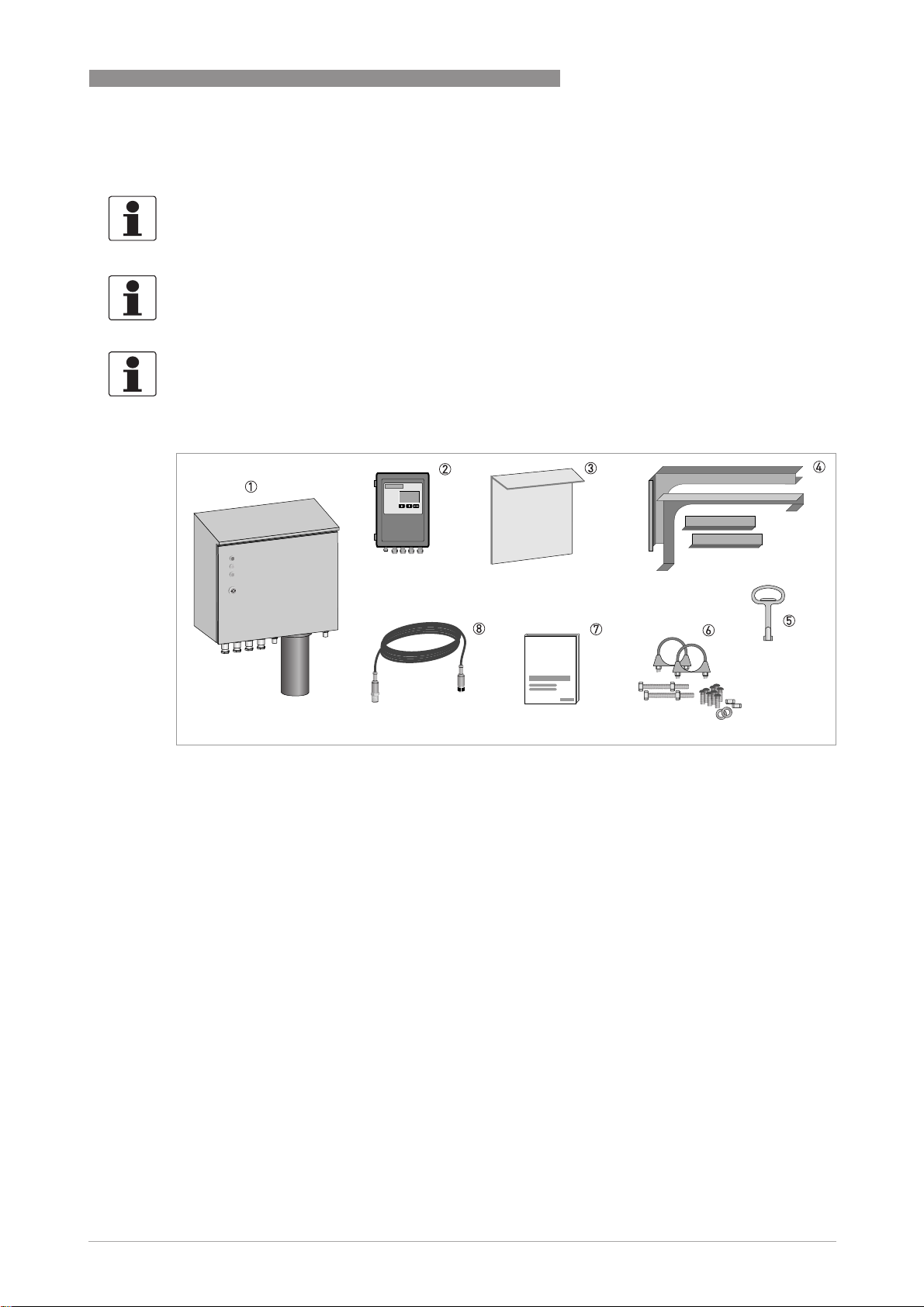
2.1 Scope of delivery
INFORMATION!
Inspect the cartons carefully for damage or signs of rough handling. Report damage to the
carrier and to the local office of the manufacturer.
INFORMATION!
Check the packing list to check if you received completely all that you ordered.
INFORMATION!
Look at the device nameplate to ensure that the device is delivered according to your order.
Check for the correct supply voltage printed on the nameplate.
DEVICE DESCRIPTION 2
1 OAM 2080 sludge blanket meter
2 Converter
3 Mounting plate for converter
4 Handrail mounting frame
5 Key for cabinet lock
6 Mounting accessories
7 Documentation
8 Signal cable (1.5 m / 4.9 ft)
For information about optional accessories refer to
Spare parts and accessories
on page 35.
www.krohne.com08/2010 - MA OPTISENS OAM 2080 R01 en
9
Page 10
2 DEVICE DESCRIPTION
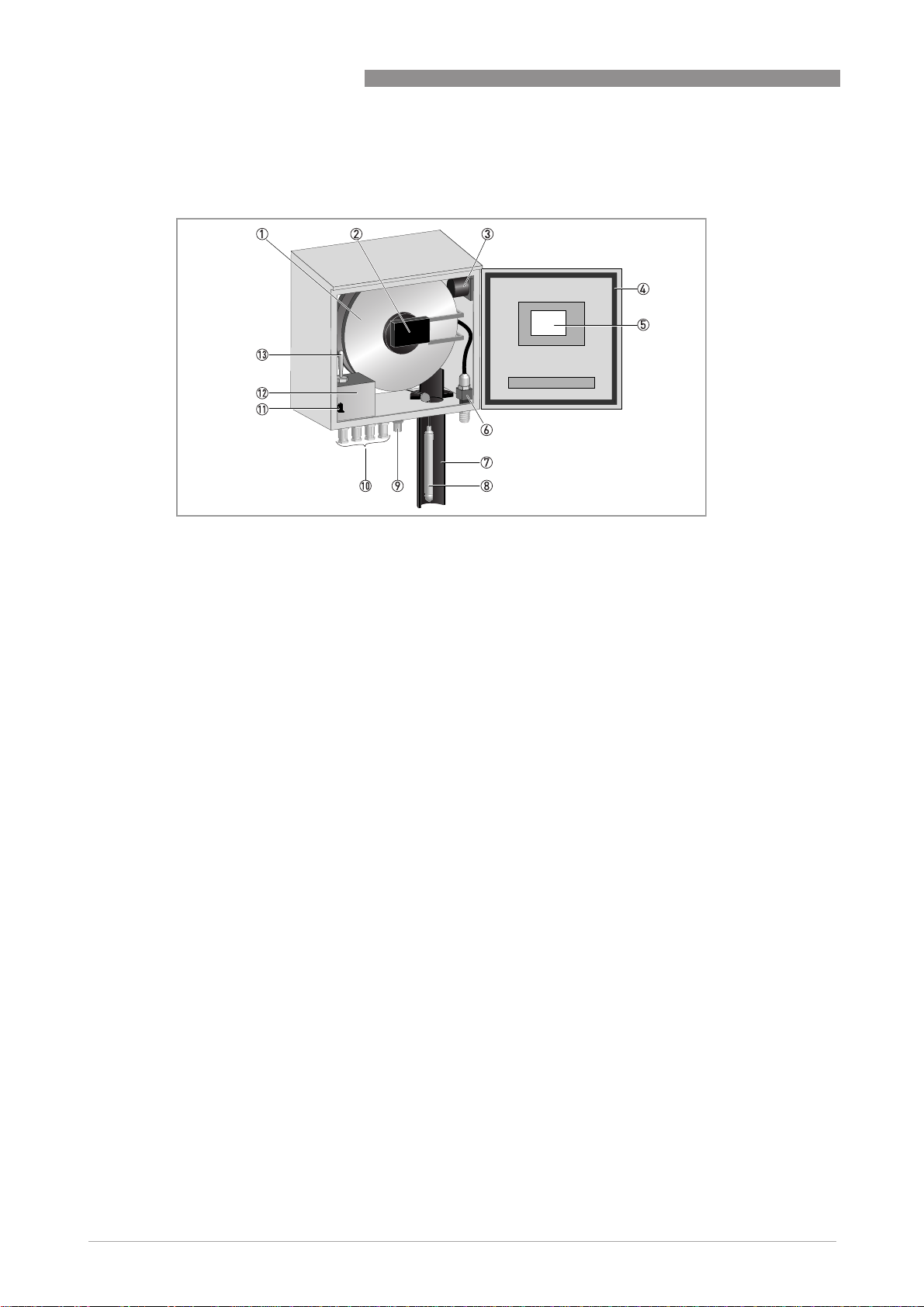
2.2 Description of the single components
OPTISENS OAM 2080
1 Cable drum assembly
2 Pickup board and axle board
3 Heater and fan
4 Gasket
5 Main electronics unit
6 Flush valve with flush hose connector
7 Flushing tube
8 Sensor
9 5-pos. M12 female connector (A-coded)
10 ½" NPT female connector
11 Safety switch
12 Junction box with terminal blocks inside
13 Manual hauling switch
14 Cable connection terminal
Cable drum assembly
The cable drum helps to move the sensor up and down in the basin. It is mounted directly on the
axle of a synchronous motor, hidden behind the drum mounting plate.
The cable drum always moves with a very constant speed. Since the diameter of the cable roll in
the drum varies, the speed of the sensor varies. That is why the sensor moves slower during the
end of the sampling.
The cable and sensor are cleaned by a water spray in the flushing tube during return to the home
position.
10
www.krohne.com 08/2010 - MA OPTISENS OAM 2080 R01 en
Page 11

OPTISENS OAM 2080
Main electronics unit
The main electronics unit is located at the front door in a separate enclosure. It controls all
mechanical events in the device and communicates with both the sensor and the converter. The
communication with the converter is done through a RS-485 interface.
Other signals going in and out of sludge blanket meter are also conducted to the main
electronics unit. The unit collects the values of the sludge concentration from the sensor and
transmits them to the converter.
Sensor
The sensor is connected to a cable that supplies the sensor with power. The cable also transmits
the communication signals to the pickup board.
The sensor contains a near-infrared light source and a receiver. Both are positioned in such a
way that the emitted near-infrared light has to pass through the liquid before reaching the
receiver.
Cable connection terminal
The separate box in the lower left corner of the enclosure contains the connection terminal for
the external wire connections. To the left of this terminal block there is a safety switch that will
disconnect the power when the enclosure door opens.
DEVICE DESCRIPTION 2
On the top of the terminal box there is an emergency motor control switch witch the functions
"Up" and "Down". It allows to control the sensor movement even if the normal control function
does not work.
Pickup board & axle board
The pickup board is mounted on a spring loaded lever arm and transfers power and
communication signals to the cable drum. It also measures the revolutions of the cable drum
with the help of sensors.
The axle board on the cable drum is powered contactlessly ("inductively") from the pickup board.
It communicates with the main electronics unit via the pickup board and with the sensor via an
optical RS-485 interface.
Heater & fan
The heater is located behind the drum mounting plate. Together with the fan it maintains a
stable temperature inside the enclosure of the meter. The position of the fan is on the top right
side of the enclosure.
www.krohne.com08/2010 - MA OPTISENS OAM 2080 R01 en
11
Page 12
2 DEVICE DESCRIPTION
Flush tube and flush valve
The flush tube contains a nozzle ring that sprays cleaning water around the sensor and cable.
Each time the sensor moves upwards into the flush tube, the cleaning works until the sensor
reaches its highest position ("home position"). In that way the sensor keeps clean and the
measurement is reliable in most environments and processes.
In the home position the sensor is completely covered by the flush tube, which contains an
inductive limit switch. The switch determines the point when the sensor reaches its home
position.
Flushing starts when the built-in solenoid flush valve opens. Its control is the task of the main
electronics unit.
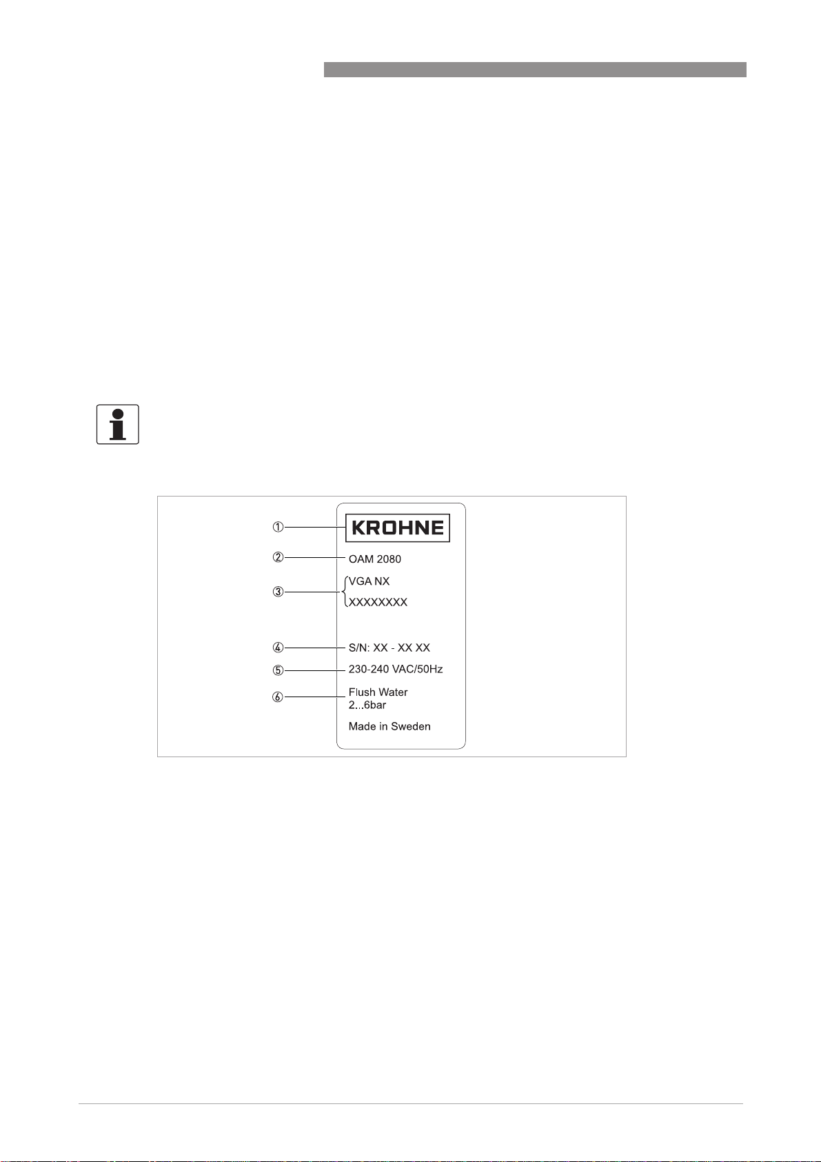
2.3 Nameplate
INFORMATION!
Look at the device nameplate to ensure that the device is delivered according to your order.
Check for the correct supply voltage printed on the nameplate.
OPTISENS OAM 2080
12
1 Manufacturer
2 Device type
3 Order code
4 Serial number
5 Voltage information
6 Pressure specification for flushing
www.krohne.com 08/2010 - MA OPTISENS OAM 2080 R01 en
Page 13

OPTISENS OAM 2080
3.1 Notes on installation
INFORMATION!
Inspect the cartons carefully for damage or signs of rough handling. Report damage to the
carrier and to the local office of the manufacturer.
INFORMATION!
Check the packing list to check if you received completely all that you ordered.
INFORMATION!
Look at the device nameplate to ensure that the device is delivered according to your order.
Check for the correct supply voltage printed on the nameplate.
3.2 Storage and transport
• Store and transport the device in a dry, dust-free environment.
• Store and transport the device in an environment with a temperature between -20...+60°C/
-4...+140°F.
• The original packing is designed to protect the equipment. It has to be used if the device is
transported or sent back to the manufacturer.
INSTALLATION 3
3.3 Typical measuring point
1 Mounting plate with sun roof
2 Converter
3 Sludge blanket meter
4 Handrail
5 Signal cable
www.krohne.com08/2010 - MA OPTISENS OAM 2080 R01 en
13
Page 14

3 INSTALLATION
INFORMATION!
The OAM 2080 only works in conjunction with the MAC 080 multiparameter converter which you
need for configuration, local display and transmission of the measuring results. Additionally the
converter must have the software version 3.1 or higher. The converter and the mounting plate
belong to the standard scope of delivery.
3.4 Installation order
DANGER!
Do not install the sludge blanket meter in hazardous areas, it can ignite explosive gases!
INFORMATION!
To install the measuring system in the best way, follow the steps described below. Regard that
different steps may vary in meaning, depending on the particular sensor and the number of
sensors that you want to connect to the converter.
INFORMATION!
All MAC 080 converters with a program version of 3.1 or higher are able to detect and install the
sensor automatically. This procedure starts when both the converter and the sensor are
supplied with power and the electrical connection between the devices is established.
OPTISENS OAM 2080
Steps to install the measuring system
• Mounting of converter
(for detailed information refer to the relevant chapter in the converter manual).
• Mounting of sludge blanket meter
(for detailed information refer to the relevant section in this chapter).
• Installation of flushing, if required
(for detailed information refer to the relevant section in this chapter).
• Connection of the rake guard switch, if required
(for detailed information refer to the relevant section in this chapter).
• Electrical installation of converter
(for detailed information refer to the relevant chapter in the converter manual)
• Electrical installation of the sludge blanket meter
(for detailed information refer to the relevant section in this chapter).
• Setup of converter
(for detailed information refer to the relevant chapter in the converter manual).
• Settings and calibration of the sludge blanket meter
(for detailed information refer to the relevant chapter in the manual of the meter).
14
www.krohne.com 08/2010 - MA OPTISENS OAM 2080 R01 en
Page 15

OPTISENS OAM 2080
3.4.1 Mounting, adjusting and fixing of meter and frame
INFORMATION!
All needed bolts, nuts and washers belong to the standard scope of delivery. The most common
application is to fix the stand on a handrail as shown in the following instructions.
Step 1: Assembling of stand
• Assemble the two brackets and two crossbar braces with the help of bolts, nuts and washers
according to the following drawing.
INSTALLATION 3
www.krohne.com08/2010 - MA OPTISENS OAM 2080 R01 en
15
Page 16

3 INSTALLATION
Step 2: Fixing stand
• Fix the U-Bolts to the handrail according to the following drawing.
• Fix the frame to the U-Bolts, ask a second person for help.
Step 3: Fixing of meter
• Fix the meter to the upper part of the brackets with the help of bolts and washers according to
the following drawing.
OPTISENS OAM 2080
16
www.krohne.com 08/2010 - MA OPTISENS OAM 2080 R01 en
Page 17

OPTISENS OAM 2080
Step 4: Adjusting
• Open the door of the meter for 45°.
• Adjust the meter horizontally using the last two screws that you screw in the lower part of the
frame.
• Turn the screws until the door does not move any more in the 45° position.
INSTALLATION 3
3.4.2 Installation of flushing
CAUTION!
Always regard the following items when installing and using the flushing function:
•
Do not flush the device at temperatures below 0°C/ 32°F as there is the risk of damage by
freezing water within the flush hoses and the solenoid valve!
•
Assure that all outdoor installations protect the hoses and the valve from freezing conditions.
If this is not possible, disconnect and empty all hoses!
•
Assure that the flushing water has a pressure between 2 bar / 29 psi and 6 bar / 87 psi. Below
the minimum pressure a sufficient cleaning is not possible, a water pressure above the
maximum value can cause damages.
•
Always use filtered water that is free of visible solids as they can cause damages. If this is the
case, you can also use town water.
INFORMATION!
The minimum diameter of the flush hose has to be at least 10 mm / 0.39".
www.krohne.com08/2010 - MA OPTISENS OAM 2080 R01 en
17
Page 18

3 INSTALLATION
In Europe you can connect the flush hose according to the following drawing. In the USA there
are hoses available with a fixed male connector that you can screw-in directly):
If you do not need the flushing function, you can disable it via the sensor menu. For further
information refer to
Plug the flush hose onto the ¼" NPTmale thread under the lower right hand corner of the
enclosure.
Menu for OAM 2000 sensor
OPTISENS OAM 2080
on page 31.
18
www.krohne.com 08/2010 - MA OPTISENS OAM 2080 R01 en
Page 19

OPTISENS OAM 2080
4.1 Safety instructions
DANGER!
All work on the electrical connections may only be carried out with the power disconnected. Take
note of the voltage data on the nameplate!
DANGER!
Observe the national regulations for electrical installations!
WARNING!
Observe without fail the local occupational health and safety regulations. Any work done on the
electrical components of the measuring device may only be carried out by properly trained
specialists.
INFORMATION!
Look at the device nameplate to ensure that the device is delivered according to your order.
Check for the correct supply voltage printed on the nameplate.
ELECTRICAL CONNECTIONS 4
4.2 Cable connections
In the bottom lower left corner of the enclosure there are four ½" NPT female electrical
connections as cable feedthroughs to the junction box. All cables fixed on the terminal blocks go
outside the enclosure via these connections.
Right beside the ½" NPT female electrical connections there is 5-pos. M12 female connector (A-
coded). This connector is wired internally and dedicated for a tailored cable with the
corresponding male connector that belongs to the scope of delivery.
INFORMATION!
The connection cable with in the scope of delivery has 5-pos. M12 male connectors (A-coded) on
both ends. Both male connectors fit to the female connector on the converter as well as to the
connector on the bottom of the enclosure.
1 Manual hauling switch
2 Left terminal block
3 Right terminal block
4 5-pos. M12 female connector (A-coded)
5 ½" NPT female connector
6 Safety switch
www.krohne.com08/2010 - MA OPTISENS OAM 2080 R01 en
19
Page 20

4 ELECTRICAL CONNECTIONS
4.3 Connection diagram and grounding
1 Push-button (door open/closed)
2 Switch for manual hauling (up/neutral/down)
3 Spare I/Os
4 I/O for rake limit switch (24 VDC)
5 Power (live)
6 Power (earth)
7 Power (neutral)
OPTISENS OAM 2080
4.4 Rake guard limit switch
CAUTION!
To avoid damages or destructions, use a limit switch in all applications where a rake or other
moving devices may come in contact with the sensor or cable! The manufacturer does not
assume any responsibility for damages caused by the absence or malfunction of the rake guard
limit switch.
To protect the sensor and cable from being damaged or destructed by rakes or other moving
parts, the meter has an N/O contact input for the connection of an external limit switch (you have
to buy this switch with another manufacturer). The sampling cycle will only start if this switch is
closed.
The function of the limit switch is to trigger the sampling process. When the moving device (e.g.
a rake) contacts the limit switch, the sampling process starts. You can define the number of
passes of the moving device that should occur before starting the sampling process with the
help of the converter (see "Trig" in the "Advanced setup" within the menu "Settings"). For
information concerning the electrical connection of a rake guard limit refer to the next chapter.
INFORMATION!
Defining the interval of the sampling process is suitable when the position of the moving device
is well known (e.g. with surface rakes). If the moving device contacts the limit switch during
sampling, the sampling process stops and the sensor moves upwards.
20
If there is no danger for the sensor or cable to be caught by moving devices (i.e. installation in
thickeners without stirrers), you can set an alternative sampling mode in the converter
controlled by the build-in timer. In this case you must wire the connections for the rake guard
switch to one of the converter relays (for further information see section "Relay outputs" in
chapter 4 "Electrical connections" in the MAC 080 handbook) and set a timer interval in seconds,
which triggers the sampling cycle accordingly (for further information refer to
(optional)
on page 29).
www.krohne.com 08/2010 - MA OPTISENS OAM 2080 R01 en
Timer interval
Page 21

OPTISENS OAM 2080
4.5 Protection category
DANGER!
Do not install the sludge blanket meter in hazardous areas, it can ignite explosive gases!
The whole meter fulfills the protection category IP55, while the capsuled electronic fulfills IP 65,
NEMA 4.
4.6 Power supply
CAUTION!
As the meter does not have an own switch to deenergize it, the manufacturer recommends that
the power supply has an external on-off switch.
The correct power supply of the meter takes place with the help of a 3-lead cable which is
approved for the rated current and voltage.
ELECTRICAL CONNECTIONS 4
www.krohne.com08/2010 - MA OPTISENS OAM 2080 R01 en
21
Page 22

5 OPERATION
5.1 Start-up and general remarks for configuration
INFORMATION!
•
Connect the converter and the meter before starting-up! The MAC 080 converter must have
the program version 3.1 or higher, otherwise it cannot work together with the meter. If the
converter has a lower program version, always contact the manufacturer for an update!
•
You are not able to make any changes to the settings until the converter has recognized the
sensor! You have to configurate the meter with the help of the converter and its display and
buttons.
The start-up procedure of the sensor begins when both the converter and the sensor are
supplied with power and the electrical connection between the devices is established. First of all
the converter performs a self-test, then the identification of the sensor starts. During this
process, which may take up to 30 seconds, the converter display shows a rotating line between
the header and the time on the first line of the display. Afterwards a wizards appears and you
have to connect the sensor to an empty slot. For further information refer to the next section.
5.2 LED indication
OPTISENS OAM 2080
There are three LEDs (red, yellow, green) on the front door of the meter which indicate its
operation status.
Operation status Red Yellow Green
Starting up. On On On
Standby, waiting for next sampling cycle. Off Off On
Configuration mode. Off Off Blinking
Taking sample. Off Blinking Off
Configuration error (something in the
parameter settings stops the device from
operating).
Operation error (mechanical or electrical fault
that stops the device from operating).
Blinking Blinking Blinking
On Off Off
22
www.krohne.com 08/2010 - MA OPTISENS OAM 2080 R01 en
Page 23

OPTISENS OAM 2080
5.3 Input of the basic settings
5.3.1 Connection of the sensor to a slot and output
After starting-up and identifying the sensor, the converter needs to know how it shall be used.
Therefore a connection wizards with the question if you want to connect the sensor with the first
free slot appears on the converter display
Connection to a slot
• Choose "Yes" or "No" with the help of ↑ or ↓ and confirm by pressing ^.
i If you chose "Yes", the converter jumps to the choice of the 4...20 mA output. If you chose
"No", the converter jumps to the next free slot and asks again if you want to connect the
sensor.
• If you chose "No", repeat the previous procedure until you find a suitable free slot.
INFORMATION!
If no slot is free, the converter display shows an error message and demands to free slots. You
can free slots with no sensor currently connected in the converter menu; the description for this
procedure is in preparation, you will find it in the converter documentation.
OPERATION 5
INFORMATION!
If you connect an identical sensor, you can reuse the slot of the former sensor if both have the
same software revision. To quickly get the new sensor running, it inherits most of the
configuration and calibration of the old sensor. This calibration will not be perfect since it has
been done for another sensor, but it will be closer than the factory default.
After connecting the sensor with a slot the converter asks which output you want to use. If you
added a sensor to slot 1 or 2, the converter asks if the corresponding 4...20 mA output should be
used, unless another sensor uses it (you can change the use of an output in the submenu
"Analog" of the main menu "Settings", on page 31):
Second step: Choice of 4...20 mA output
• Choose "Yes" or "No" with the help of ↑ or ↓ and confirm by pressing ^.
i If you chose "Yes", the connection procedure is complete and the device returns to the
normal measuring mode. If you chose "No", the converter jumps to the next output and
asks again if you want to use it.
• If you chose "No", repeat the previous procedure until you find a free current output.
www.krohne.com08/2010 - MA OPTISENS OAM 2080 R01 en
23
Page 24

5 OPERATION
5.3.2 Definition of positions and zones
OPTISENS OAM 2080
1 Home position:
Home position: the sensor will always return to this position, which is in the flushing tube.
Home position:Home position:
2 Blind zone:
Blind zone: if the sensor detects sludge or foam in this zone during lowering, the meter does not register this detection.
Blind zone:Blind zone:
You can prevent unwanted measurement by setting this zone to be 0.3 m / 1 ft below the normal liquid surface.
3 Maximum immersion depth:
Maximum immersion depth: this is the maximum distance from the home position. The sensor will stop at this depth
Maximum immersion depth:Maximum immersion depth:
if it detects no sludge. Note: the sensor might stop and return at a shorter distance if a possibly existing limit switch
interrupts the sampling process!
4 Measuring zone:
Measuring zone: in this zone the sensor delivers measuring results and the output signal varies from 4...20 mA.
Measuring zone:Measuring zone:
5 Fluff layer:
Fluff layer: defined by the preset sludge concentration.
Fluff layer:Fluff layer:
6 Sludge blanket:
Sludge blanket: defined by the reset sludge concentration.
Sludge blanket:Sludge blanket:
7 Bottom rake zone:
Bottom rake zone: here a possibly existing bottom rake operates. The top of this zone is the height where the sensor
Bottom rake zone:Bottom rake zone:
always has to stop during lowering to avoid hitting the bottom rake.
8 Bottom rake
Bottom rake
Bottom rakeBottom rake
24
www.krohne.com 08/2010 - MA OPTISENS OAM 2080 R01 en
Page 25

OPTISENS OAM 2080
For a complete and safe sampling process the meter needs to know some of the distances
described above. Execute the following steps before starting the first measurement:
First step: changing the working mode
• Press ↑ and ^ simultaneously for 5 seconds to open the sensor menu.
• Use ↓ to select the main menu "Calibrate" and enter it by pressing ^.
• Use ↓ to select the submenu "Mode" and enter it by pressing ^.
• Use ↓ to select the option "Setup" and confirm by pressing ^.
i The cursor jumps back to the submenu "Mode".
• Press ↑ until you reach the top and then press ^ to exit the menu "Calibrate".
i You are in the main menu level now.
Second step: finding out the distances
• Use ↓ to select the main menu "Settings" and enter it by pressing ^.
• Use ↓ to select the submenu "Manual" and enter it by pressing ^.
i Now you can move the sensor upwards and downwards with ↑ or ↓, the MAC 080 display
shows the distance of the sensor from its home position and the measured consistency.
• Use ↓ to lower the sensor head 0.3 m / 1 ft below the liquid surface.
• Note this distance down, it is the length of the "blind zone" (see drawing above).
• Use ↓ to lower the sensor until it touches the bottom (you can identify this point by watching
the cable go slack).
• Use ↑ to pull up the sensor until you have about 5 cm / 2" of clearance between the bottom of
the clarifier and the sensor.
• Note the distance down, it is the "maximum depth" (see drawing above).
• Exit the submenu "Manual" by pressing ^.
i The sensor moves upwards to its home position and the cursor jumps to the main menu
"Settings".
OPERATION 5
Third step: entering the distances
• In the main menu "Settings" use ↑ or ↓ to go to the submenu "Advanced setup" and enter it by
pressing ^.
• Within the submenu "Advanced setup" select the option "Max depth", enter the value you have
found out with the help of ↑ and ↓ and press ^ to confirm.
• Use ↓ to go to the option "Blind zone" and repeat the procedure of the previous step.
• Optionally you can go to the option "Rake height" with the help of ↓ and repeat the procedure
of the previous step (be aware that you cannot find out the rake height or slope with the help of
lowering the sensor, you have to ask for these values).
• Press ↑ until you reach the top and press ^ to exit the submenu "Advanced setup".
i You are in the main menu "Settings" again.
www.krohne.com08/2010 - MA OPTISENS OAM 2080 R01 en
25
Page 26

5 OPERATION
Fourth step: entering the consistencies and returning to measuring mode
• In the main menu "Settings" use ↓ to go to the submenu "Blanket Cons" and enter it by
pressing ^.
• Enter the consistency that will define the detection of the sludge blanket with the help of ↑
and ↓.
• Press ↑ until you reach the top and exit the submenu "Blanket Cons" by pressing ^.
• If necessary repeat the previous steps with the fluff consistency ("Fluff Cons", next submenu
after "Blanket Cons").
• Press ↑ until you reach the top, then press ^ to exit the main menu "Settings".
• Go to the main menu "Calibrate" and change the working mode as described in the first step.
• Leave the sensor menu by pressing ↑ and ^ for 5 seconds.
i The meter is in the normal measuring mode now.
5.4 Scaling of a 4...20 mA output
The scaling function allows the user to set the high and low boundaries for a 4...20 mA output
signal. In addition, this menu offers the opportunity to set the high and low alarm values to
switch a relay when the solid concentration has reached a critical point. For further information
refer to
Menu for OAM 2000 sensor
OPTISENS OAM 2080
on page 31.
5.5 Calibration
Before leaving the factory the sensor is calibrated to offer an accurate measurement. Though it
might be necessary to re-calibrate the sensor during the lifetime of the system.
INFORMATION!
Even after the installation, a re-calibration with sludge might improve the accuracy. Zero
calibration is done with clean, de-aerated water in a bucket. Sludge calibration is done with a
known sample in a bucket.
Running a calibration
• Press ↑ and ^ simultaneously for 5 seconds to open the sensor menu.
• Use ↓ to go to the menu "Calibrate" and enter it by pressing ^.
• Use ↓ to choose the submenu "Mode" and enter it by pressing ^.
• Use ↓ to choose the option "Setup" and press ^.
i The cursor jumps back to the submenu "Mode", the green LED on the door blinks and will
continue blinking while making changes.
• Use ↓ to choose the submenu "Manual" and enter it by pressing ^.
i Now you can move the sensor upwards and downwards with ↑ or ↓, the MAC 080 display
shows the distance of the sensor from its home position and the measured consistency.
• Lower the sensor with the help of ↓ and position it approximately 1 m / 3.3 ft under the
flushing tube.
• Put the sensor into a bucket with clean water (zero calibration) or sludge (sludge calibration).
• Leave the submenu "Manual" by pressing ^.
i The manual hauling function is now disabled again and the cursor is in the main menu
"Calibrate".
• Use ↓ to go to the submenu "Take sample" and press ^.
• Use ↓ to choose either "Zero" (zero calibration) or "Sample" (sludge calibration); you can also
choose "No" if you want to leave the submenu without calibration.
• Press ^ to initiate the measuring process.
26
www.krohne.com 08/2010 - MA OPTISENS OAM 2080 R01 en
Page 27

OPTISENS OAM 2080
i The device measures the consistency of the clean water or the sludge. In case of zero
calibration the displays shows the message "Zero calibration done" at the end, in case of
sludge calibration the display shows the measured value in a new pop-up window.
• In case of a sludge calibration press ^ to store the value and take the sample to a laboratory
to determine the sludge content.
• Irrespective of the calibration type press ^ to close all messages and return to the submenu
level of the main menu "Calibrate".
• If you want to return to the normal measuring mode, go to the submenu "Mode" again and
choose the option "Trig" (procedure is similar to the one on the beginning of this
actionsequence).
i The green LED on the door now burns steadily.
• Press ↑ and ^ for 5 seconds to go to the normal measuring mode.
Entering the laboratory result (sludge calibration)
• Press ↑ and ^ simultaneously for 5 seconds to open the sensor menu.
• Use ↓ to go to the menu "Calibrate" and enter it by pressing ^.
• Use ↓ to choose the submenu "Sample" and enter it by pressing ^.
• Enter the laboratory result with the help of ↑ or ↓and confirm by pressing ^.
i The converter will automatically correct the sludge consistency value from now on.
OPERATION 5
• Return to the normal measuring mode by pressing ↑ and ^ for 5 seconds.
5.6 Manual hauling
The meter has a manual hauling function. With the help of the safety switch you can override the
main board control of the cable drum motor and make the sensor go up or down with the manual
hauling switch ( refer to
go up might be necessary for example if the meter stops functioning correctly during an active
sample.
For manual hauling execute the following steps and :
• Open the enclosure with the help of the key you find in the scope of delivery.
• Press the safety switch coming out of the front side of the connection terminal box to supply
the device with power.
• To make the sensor go up or down use the manual hauling switch on the top of the connection
terminal box (the switch has three positions: up/neutral/down).
Description of the single components
on page 10). Forcing the sensor to
www.krohne.com08/2010 - MA OPTISENS OAM 2080 R01 en
27
Page 28

5 OPERATION
5.7 Display of sludge profile (optional)
INFORMATION!
This function requires an expansion module with two more 4...20 mA outputs in the MAC 080
converter. Altogether the converter has four outputs with the extra card. For detailed
information about the installation of the converter expansion module refer to the section
"Description of additional analog outputs" in the converter manual.
When using the profile function, the single channels transmit the following measuring results
(refer to on page 24 for information concerning the positions and zones):
Channel Measuring result
OPTISENS OAM 2080
1 Height of sludge blanket, every new measurement updates the signal. The
2 Height of fluff blanket, every new measurement updates the signal.
3 Consistency, displayed in real-time during a measurement (otherwise 0 mA if
4 Depth of sensor, displayed in real-time during a measurement (otherwise the
Execute the following steps to activate the profile function:
• Press ↑ and ^ simultaneously to enter the sensor menu.
• Use ↓ to go to the main menu "Settings" and enter it by pressing ^.
• Use ↓ to go to the submenu "Analog" and enter it by pressing ^.
• Use ↓ to choose "All" and confirm by pressing ^.
• Press ↑ until you reach the top and press ^ to exit the submenu "Analog".
scale is defined by the maximum and minimum value entered in the menu
"Scale / Alarm".
no measurement takes place), scale is locked to 0...10000 mg/l.
output channel remains on 20 mA if no measurement takes place).
i You are in the main menu "Settings" again.
• Use ↓ to go to the submenu "Second" and enter it by pressing ^.
• Use ↓ to choose "Fluff" and confirm by pressing ^.
• Press ↑ until you reach the top and press ^ to exit the submenu "Second".
i You are in the main menu "Settings" again.
• Use ↓ to go to the submenu "Advanced setup" and enter it by pressing ^.
• Use ↓ to go to the option "Track" and enter it by pressing ^.
• Use ↓ to go to "Profile" and confirm by pressing ^.
• Exit the submenu "Advanced setup" by pressing ↑ and ^ for five seconds.
• Leave the sensor menu by pressing ↑ and ^ for 5 seconds.
i The meter is in the normal measuring mode now.
28
www.krohne.com 08/2010 - MA OPTISENS OAM 2080 R01 en
Page 29

OPTISENS OAM 2080
Example of a typical sludge profile
OPERATION 5
1 Immersion depth of the sensor in centimetres
2 Consistency in mg/l
3 Time axis
4 Level measurement curve
5 Consistency curve
6 Sludge layer curve
7 Fluff layer curve
In the previous drawing the expansion of the sludge blanket is 0.3 m / 1 ft and of the fluff layer it
is 0.9m/ 3ft.
5.8 Timer interval (optional)
To protect the sensor and the cable from damages or destruction by rakes or other moving
parts, a rake guard limit switch can control the measuring cycle ( on page 20).
If there is no danger for the sensor or cable to be caught by moving devices (i.e. installation in
thickeners without stirrers), you can set an alternative sampling mode controlled by the build-in
timer. In this case you have execute the following steps to select the trigger relay in the
converter and set the time interval in minutes:
www.krohne.com08/2010 - MA OPTISENS OAM 2080 R01 en
29
Page 30

5 OPERATION
• Press ↑ and ^ simultaneously for 5 seconds to open the sensor menu.
• Use ↓ to go to the menu "Timer" and enter it by pressing ^.
• Use ↓ to go the submenu "Timer" and enter it by pressing ^.
• Use ↓ to go the option "On" and press ^.
• Use ↓ to go the submenu "Interval min" and enter it by pressing ^.
• Use ↑ and ↓ to set the timer interval in minutes and confirm by pressing ^.
• Use ↓ to go the submenu "Relay" and enter it by pressing ^.
• Use ↑ and ↓ to select the relay to which the rake guard contacts are wired to and confirm by
pressing ^.
• Return to the normal measuring mode by pressing ↑ and ^ for 5 seconds.
5.9 Faults: reasons and remedies
Complete stop of all operations, no indication on converter display
The reason for this case may be a surge of external power. Irrespective of the reason you can
perform a reset by switching the device off and on. For this purpose open the front door and
close it again.
Furthermore the device can detect a number of errors. In this case the alarm contact closes and
the display shows a message in plain text that indicates the kind of error. Each error may stop
the device, you can soft reset it by pressing ^ on the converter and if this does not work you can
make a hard reset as described above:
OPTISENS OAM 2080
Message "SENSOR TILT" on converter display
This message indicates that the sensor has tilted more than 45 degrees and that the tilt switch in
the sensor has detected this. In this case the converter not only shows a message, but the
sensor also goes up to its home position.
Message "SENSOR ERROR" on converter display
This message indicates that the converter does not receive any signals from the sensor. In this
case the converter not only shows a message, but the sensor also goes up to its home position.
Message "SENSOR STOPPED" on converter display
This message indicates that the cable drum is standing still though it should move.
30
www.krohne.com 08/2010 - MA OPTISENS OAM 2080 R01 en
Page 31

OPTISENS OAM 2080
5.10 Menu for OAM 2000 sensor
Use ↑ or ↓ to select the sensor in the main display. The menu for the selected sensor is accessed
by pressing ^ for five seconds. If the selected sensor is not active (the text No transmitter
shown) a warning is displayed that asks you to make another choice in order to show the sensor
menu.
Menu "Settings"
Submenu Option Description
Tag
Tag Name of the sensor shown in the main display (10 characters).
TagTag
I-Time(s)
I-Time(s) Integration time or damping, can be set up to 999 seconds.
I-Time(s)I-Time(s)
Manual
Manual This submenu enables a function in the MAC 080 that allows to
ManualManual
Depth Unit
Depth Unit Unit used for distances in OAM 2080 settings. Available options:
Depth UnitDepth Unit
Cons Units
Cons Units Unit used for consistency. Available options: "%", "ppm", "g/l",
Cons UnitsCons Units
Analog
Analog Sets the analog output channels for sludge blanket depth as
AnalogAnalog
Second
Second The second output shows the height of the fluff layer from the
SecondSecond
Blanket Cons
Blanket Cons Sets the consistency that will define the detection of the sludge
Blanket ConsBlanket Cons
Fluff Cons
Fluff Cons Sets the consistency that will define the detection of the fluff
Fluff ConsFluff Cons
Advanced setup
Advanced setup Submenu for initial setup of the OAM 2080 with the following
Advanced setupAdvanced setup
Mains frequ The frequency of the power (i.e. 50 Hz in Europe and 60 Hz in the
Trig Number of trig event before lowering the sensor, you can enter up
Max depth Maximum travel distance from the home position. The sensor will
Blind zone Distance to where the sensor must travel before it starts to
OPERATION 5
No transmitter is
No transmitterNo transmitter
move the sensor up or down with the help of the converter
buttons ↑ or ↓. In the manual control mode the converter display
shows the depth of the sensor and the measured consistency.
Note: To use this submenu the device has to work in the operation
mode "Trig" (see menu "Calibrate", submenu "Mode")!
m, cm, inch, foot.
"mg/".
primary and second analog for fluff if used. Available options: -
(none), all, 1, 2, 3 or 4,available combinations: "1&2" or "3&4".
bottom. Depending on the chosen channel as primary this can be
channel 2 or 4.
blanket. This function provides the opportunity to enter the
blanket consistency.
layer. This function provides the opportunity to enter the fluff
consistency.
options:
USA).
to 2 digits.
stop at this depth if no blanket or sludge is detected. The travel
distance will be shortened if a rake offset is set (refer to on page
24 for information concerning the positions and zones).
measure solids. Sludge or foam detected in this zone during
lowering is not registered. Unwanted registration is prevented by
setting this zone to reach approximately 25 cm / 0,82 ft below the
liquid surface (refer to on page 24 for information concerning the
positions and zones).
www.krohne.com08/2010 - MA OPTISENS OAM 2080 R01 en
31
Page 32

5 OPERATION
Submenu Option Description
OPTISENS OAM 2080
Rake height In case of a bottom rake or a slope, this parameter is subtracted
Track This option determines where the measuring cycle stops. The
from the maximum depth to set the actual stop. At this point the
sensor will stop and return home in the case that there is no
sludge (refer to on page 24 for information concerning the
positions and zones).
setting "Level" effects that the measurement stops when the
sensor detects the sludge blanket (as defined in the submenu
"Blanket Cons"). The setting "Profile" runs each measuring cycle
over the complete measuring zone, i.e. the sensor goes to the
maximum immersion depth.
Menu "Calibrate"
Submenu Option Description
Mode
Mode There are two operation modes:
ModeMode
Setup Allows to change the calibration parameters or to use the
Trig Normal working mode, in which the device will take a sample on
Manual
Manual For further information see submenu "Manual" in the menu
ManualManual
Take sample
Take sample Choice of the calibration type.
Take sampleTake sample
No To abort calibration.
Zero To perform a zero point calibration.
Sample To perform a sludge calibration.
Cons
Cons Makes the display showing only the current consistency.
ConsCons
Sample
Sample This function provides the opportunity to enter the consistency
SampleSample
"MANUAL UP/DOWN" button.
every external trig.
"Settings".
(i.e. suspended solids value) from a laboratory test.
32
www.krohne.com 08/2010 - MA OPTISENS OAM 2080 R01 en
Page 33

OPTISENS OAM 2080
Menu "Cleaning"
Submenu Option Description
Cleaning
Cleaning
CleaningCleaning
Manual
Manual For further information see submenu "Manual" in the menu
ManualManual
Menu "System"
Submenu Option Description
Type
Type Type of the sensor (read-only information).
TypeType
Serial
Serial Serial number of the sensor (read-only information).
SerialSerial
SoftW
SoftW Software version of the sensor (read-only information).
SoftWSoftW
Info
Info
InfoInfo
OPERATION 5
Yes Flush cleaning is switched on.
No Flush cleaning is switched off.
"Settings".
Ch1 Raw value of height (no unit).
Ch2 Raw value of consistency in mV.
Ch3 Not used
Ch4 Not used
Samples Counter that shows the total number of samples taken by the
device on that day.
Menu "Scale / Alarm"
Submenu Description
Max
Max Upper end of the measuring zone, equal to an output signal of 20 mA.
MaxMax
Min
Min Lower end of the measuring zone, equal to an output signal of 4 mA.
MinMin
Hi-Alarm
Hi-Alarm Maximum fill level of the basin, here the device produces an alarm.
Hi-AlarmHi-Alarm
Low-Alarm
Low-Alarm Minimum fill level of the basin, here the device produces an alarm.
Low-AlarmLow-Alarm
Alarm Relay
Alarm Relay Alarm relay that should be used on the converter, options: - (none) 1, 2, or 1 & 2.
Alarm RelayAlarm Relay
Note: check that the relay is not being used for cleaning!
Menu "Timer"
Submenu Description
Timer
Timer Allows to switch the timer on or off using one alarm relay to trigger the measuring
TimerTimer
Interval min
Interval min Sets the timer interval in minutes.
Interval minInterval min
Relay
Relay Selects relay to operate solenoid valve for the timer function. Options: - (none) 1
RelayRelay
Next time
Next time Sets the scheduled time for the next measuring cycle. Pushing ↑ sets the time to
Next timeNext time
cycle via a timer.
or 2.
the current time and starts a measuring cycle (this could be used to test the timer).
www.krohne.com08/2010 - MA OPTISENS OAM 2080 R01 en
33
Page 34

6 SERVICE
6.1 Manual initiation of a measurement
For service or maintenance you can manually initiate a measurement:
• Press ↓ on the converter for five seconds.
i The meter starts with a measurement cycle as soon as possible: the sensor goes down to
the defined maximum depth and returns to its home position, afterwards the meter works
in the normal mode.
• To stop the sensor during lowering and force it to return to its home position press ↑ on the
converter.
6.2 Maintenance
Maintenance schedule
Maintenance action Once a month Once every six months Once a year
OPTISENS OAM 2080
Visual check of sensor
and clean if necessary.
Visual check of lenses
and clean if necessary
Visual check of cable
and drum
Cleaning or
replacement of air filter
Check of fan - - X
Check of screws and
nuts
Sensor check in water - - X
X X X
- X X
- X X
- - X
- - X
Visual check and cleaning of sensor
Check the sensor for any buildup, i.e. a large amount of dirt. If necessary, clean it with a damp
soft cloth.
Visual check and cleaning of lens
Check the lens for any buildup or film. If necessary, clean it with a suitable agent like water or
isopropyl alcohol and a soft rag.
Visual check of cable and drum
Check the cable, it must not have any damages or wear and has to be spooled correctly on the
drum. Always replace the cable if it shows any damage or severe wear of the insulation!
34
If the cable is not correctly spooled up or shows a large amount of dirt, lower the sensor
manually to the maximum position ( refer to
Manual hauling
on page 27) at first. During back
hauling monitor the correct guidance of the cable and that it spools up properly, clean it with a
soft cloth if necessary.
www.krohne.com 08/2010 - MA OPTISENS OAM 2080 R01 en
Page 35

OPTISENS OAM 2080
Cleaning or replacement of air filter
You might need to clean or replace the air filter if the meter works in a dusty environment. For
that purpose execute the following steps:
• Remove the cover from the outside.
• Remove the protective grating with a screwdriver and put it back by pressing it by hand.
• Clean the air filter or take a new one if cleaning is not possible.
• Reassemble the devices in reverse order.
Check of fan
Make sure that the fan starts every time when the sensor is on the way up.
Check of screws and nuts
Verify that every screw or nut is properly secured and that no loose parts are rattling.
Sensor check in water
Check the sensor by immersion in water, this should give a low measuring value or even a "0" on
the converter display. By placing something solid (e.g. your finger) in the gap between the LED
and the sensor you should get a measuring value of 3000...9999 (depending on the calibration).
SERVICE 6
6.3 Spare parts and accessories
INFORMATION!
All spare parts and accessories do not have any order codes, just contact the manufacturer.
• Signal cable (1.5 m / 4.9 ft)
• Signal cable extensions (10 m / 32.8 ft or 30 m / 98.4 ft)
• Sensor with cable
• Air filter
• Flushing valve (115 V or 230 V)
• Electric motor (115 V or 230 V)
• Fan (115 V or 230 V)
www.krohne.com08/2010 - MA OPTISENS OAM 2080 R01 en
35
Page 36

6 SERVICE
6.4 Spare parts availability
The manufacturer adheres to the basic principle that functionally adequate spare parts for each
device or each important accessory part will be kept available for a period of 3 years after
delivery of the last production run for the device.
This regulation only applies to spare parts which are under normal operating conditions subjects
to wear and tear.
6.5 Availability of services
The manufacturer offers a range of services to support the customer after expiration of the
warranty. These include repair, technical support and training.
INFORMATION!
For more precise information, please contact your local representative.
6.6 Returning the device to the manufacturer
OPTISENS OAM 2080
6.6.1 General information
This device has been carefully manufactured and tested. If installed and operated in accordance
with these operating instructions, it will rarely present any problems.
CAUTION!
Should you nevertheless need to return a device for inspection or repair, please pay strict
attention to the following points:
•
Due to statutory regulations on environmental protection and safeguarding the health and
safety of our personnel, manufacturer may only handle, test and repair returned devices that
have been in contact with products without risk to personnel and environment.
•
This means that the manufacturer can only service this device if it is accompanied by the
following certificate (see next section) confirming that the device is safe to handle.
CAUTION!
If the device has been operated with toxic, caustic, flammable or water-endangering products,
you are kindly requested:
•
to check and ensure, if necessary by rinsing or neutralizing, that all cavities are free from
such dangerous substances,
•
to enclose a certificate with the device confirming that is safe to handle and stating the
product used.
36
www.krohne.com 08/2010 - MA OPTISENS OAM 2080 R01 en
Page 37

OPTISENS OAM 2080
6.6.2 Form (for copying) to accompany a returned device
Company: Address:
Department: Name:
Tel. no.: Fax no.:
Manufacturer's order no. or serial no.:
The device has been operated with the following medium:
SERVICE 6
This medium is: water-hazardous
toxic
caustic
flammable
We checked that all cavities in the device are free from such
substances.
We have flushed out and neutralized all cavities in the
device.
We hereby confirm that there is no risk to persons or the environment through any residual media
contained in the device when it is returned.
Date: Signature:
Stamp:
6.7 Disposal
CAUTION!
Disposal must be carried out in accordance with legislation applicable in your country.
www.krohne.com08/2010 - MA OPTISENS OAM 2080 R01 en
37
Page 38

7 TECHNICAL DATA
7.1 Measuring principle
The sensor is let down into the clarifier or thickener and measures the suspended solids
concentration. While it descends, it transmits the data via a communication cable to the MAC 080
converter. By submersing the sensor into the liquid, you are able to obtain reliable suspended
solids readings and avoid problems from foam and fluff layers in the clarifier or thickener.
The sensor measures transmitted light through the liquid. The measuring principle is based on
the suspended particles ability to absorb and reflect NIR (Near Infra-red) light. The light source
is a light emitting diode that pulses and emits monochromatic light with a wavelength of 880 nm
(see drawing below).
The detected measuring signal is inversely logarithmical proportional to the concentration of
suspended solids. Signal treatment or linearization is done within the converter. In addition, the
temperature is measured to be used for temperature compensation of the measured value.
INFORMATION!
The built-in temperature measurement is not a precision measurement, but shall be seen as an
indication.
OPTISENS OAM 2080
4
Figure 7-1: Cross-section of measuring gap
1 Measuring gap
2 Light source (NIR-LED)
3 Monochromatic light beam
4 Detector
1
3
2
38
www.krohne.com 08/2010 - MA OPTISENS OAM 2080 R01 en
Page 39

OPTISENS OAM 2080
7.2 Technical data
INFORMATION!
•
The following data is provided for general applications. If you require data that is more
relevant to your specific application, please contact us or your local representative.
•
Additional information (certificates, special tools, software,...) and complete product
documentation can be downloaded free of charge from the website (Download Center).
Measuring system
Measuring principle Reflection and absorption of light on suspended solids and sludge
Application range Continuous measurement of the suspended solids concentration in
Design
Features • Usage of NIR (Near Infra-red) light with 880 nm
Modular construction A typical measuring system consists of the MAC 080 multiparameter
Measuring range 0...20000 mg/l, depending on sludge type (Note: the factory
Drive Lowering speed: maximal 15 cm / 5,9" per second, 12,5 cm / 4,9" at
Rake guard switch Closing contact normally open, 24 VDC is supplied from OAM 2080.
Display and user interface Refer to MAC 080 handbook.
Internal heating "Off" above 15°C/ 59°F, full power below 5°C/ 41°F.
Transmission of measuring
results
TECHNICAL DATA 7
particles. The light passes the measured particles between the
emitter and the detector of the optical sensor in a straight line.
waste water and sludge (e.g. in aeration basins).
• Reference measurement
• Temperature-compensated
converter and the OAM 2080 main unit.
calibration was done for the range 0...14000 mg/l).
Sensor can be let down and is waterproofed up to 10 m / 32,8 ft
maximum immersion depth.
50 Hz
Full cycle time for 10 m / 32,8 ft: 3 min
Via 4...20 mA outputs (or optional via Profibus DP) to the converter.
Measuring accuracy
Reference conditions Medium: water
Temperature: 20°C/ 68°F
Pressure: ambient
Maximum measuring error
(sensor)
Maximum measuring error
(immersion depth)
5% full scale
0,5% full scale
www.krohne.com08/2010 - MA OPTISENS OAM 2080 R01 en
39
Page 40

7 TECHNICAL DATA
Operating conditions
Temperatures and pressure
Temperatures and pressure
Temperatures and pressureTemperatures and pressure
Ambient temperature -20...+50°C / -4...+122°F
Process temperature 0...+50°C / +32...+122°F
Storage temperature -10...+60°C / +14...+140°F
Maximal immersion depth 10 m / 32,8 ft
Water pressure (process) Ambient
Water pressure (flushing) 2...6 bar / 29...87 psi
Protection category IP 55
Installation conditions
Installation position Fixing on a handrail at open channels, basins or tanks.
Dimensions & weights For detailed information refer to the section "Dimensions and
Materials
Enclosures Whole meter and sensor: SIS 2343 (316 SS)
Connection cable to converter Polyurethane
OPTISENS OAM 2080
weights".
Electrical connections
Power supply (voltage) Europe: 230...250 VAC at 50 Hz
USA: 115 VAC at 60 Hz
Power consumption Maximal 450 W
Fuse 5 A (T1AH, 20 x 5 mm)
Connection cable to converter 5-pin M12 contact, shielded, 1,5 m / 4,9 ft long (extension cables
Input and output (converter) Refer to technical documentation of the relevant converter.
optionally available).
Approvals and certifications
CE The device fulfils the statutory requirements of the EC directives.
EMC Electromagnetic compatibility (EMC) in accordance with:
Low Voltage Directive Safety requirements for electrical equipment for measurement,
The manufacturer certifies that these requirements have been met
by applying the CE marking.
• EN 61000-6-4:2001 (Emission standard for industrial environments)
• EN 61000-6-2:2001 (Immunity for industrial environments)
control and laboratory use in accordance with EN 61010-1:2001.
40
www.krohne.com 08/2010 - MA OPTISENS OAM 2080 R01 en
Page 41

OPTISENS OAM 2080
7.3 Dimensions
TECHNICAL DATA 7
Dimensions [cm] Dimensions ["] Weight
[kg] [lbs]
a 40 15.7 20
b 21.1 8.3
c 34 13.4
d 10 3.9
e 30 11.8
f 40 15.8
g 7.9 3.1
h 3.3 1.3
j 21.1 8.3
20 44
2020
44
4444
www.krohne.com08/2010 - MA OPTISENS OAM 2080 R01 en
41
Page 42

8 NOTES
OPTISENS OAM 2080
42
www.krohne.com 08/2010 - MA OPTISENS OAM 2080 R01 en
Page 43

OPTISENS OAM 2080
NOTES 8
www.krohne.com08/2010 - MA OPTISENS OAM 2080 R01 en
43
Page 44

KROHNE product overview
• Electromagnetic flowmeters
• Variable area flowmeters
• Ultrasonic flowmeters
• Mass flowmeters
• Vortex flowmeters
• Flow controllers
• Level meters
• Temperature meters
• Pressure meters
• Analysis products
• Measuring systems for the oil and gas industry
• Measuring systems for sea-going tankers
Head Office KROHNE Messtechnik GmbH
Ludwig-Krohne-Str. 5
D-47058 Duisburg (Germany)
Tel.:+49 (0)203 301 0
Fax:+49 (0)203 301 10389
info@krohne.de
The current list of all KROHNE contacts and addresses can be found at:
© KROHNE 08/2010 - MA OPTISENS OAM 2080 R01 en - Subject to change without notice.
www.krohne.com
 Loading...