

Page 1

CORIMASS
Instructions to use with
Krohne SMART or HART
MFC 081 / 085 Mass Flow Converters
KROHNE SMART
HART
Instruction Manual
®
Communications Protocol
®
and
Hart is a registered trademark of the HART Communication Foundation
Page 2

Contents
1. The Krohne SMART System 3
1.1 Description of Operation 3
1.2 SMART overview 3
1.3 Connecting the PC or Hand-held Communicat or 4
1.4 PC CONFIG Software Package 5
1.5 Further Instruction Manuals 5
®
2. The HART
Protocol 6
2.1 Method of Operation 6
2.2 Point to point O perati on 6
2.3 HART
®
Protocol Structur e 7
2.4 Hand-held Communi cat or 9
2
Page 3
1. The Krohne SMART System
1.1 Description of oper at ion
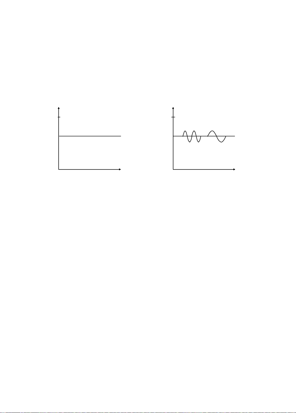
The interface for the Krohne Smart system is the current output. Bi - di r ecti onal inform at ion can
be transmitted via the current output cables. The current output signal (0/4 to 20 mA is not
affected because the mean value of the signal containi ng the digit al informati on is equal to
zero.
The signals are superimposed by means of frequency shift keying (FSK), based on the Bell
202 comm uni cat ion standard. The digital t r ansmission signal is form ed from two frequencies:
2200 Hz = “0” and 1200 Hz = “1”.
MEASURED
VALUE
0 mA 0 mA
TIME TIME
CONVENTIONAL SMART FSK MODE
MEASURED
VALUE
20 mA20 mA
2200 Hz
“0”
1200 Hz
“1”
The Smart technology will enable you to utilize its advantages for initial start up, maintenance
work and to change settings. All parameters for new measuring devices (in this case, the
mass flow m eter or m eters) or those to be changed can be defined and entered into the PC in
the workshop. The stored data can then be downloaded to the mass flow meter and started up
from t he control r oom (via the cable marshal l ing rack).
The same applies to operation and maint enance. The status of the mass flow meter can be
displayed on-line, or in t est mode, the current output can be set t o a specific val ue or values in
order to test the whole circuit. If a converter is r eplaced, the parameter set from the data base
(PC) can be downloaded into the new converter. Thi s elimi nates tim e consuming data entry
and programming. The possibility of errors being incurred during programming is also
eliminated.
1.2 SMART overview
All Krohne Smart si gnal converters may be operated via PC. The transmission route m ay be
up to 1600 m / 5250 f t long. The load between the coupling part of the PC and the converter
output loop should be at least 100 ohms.
Note: This protocol is not compatibl e with HART
even though it uses a similar method of
comm unication.
3
Page 4
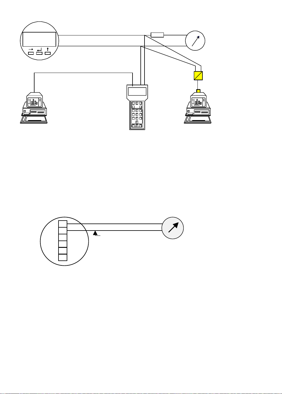
MFC 081/085
SMART
0/4 - 20 mA + FSK
LOAD
SMART Converter
AdaptorMIC 500
Data can be transferred
between a PC and MIC 500 or
vice versa
CONFIG Program
communicates directly
with converter
1.3 Connecting the PC
The PC can only be connected to the first current output of the MFC 081/085, i.e. current
output from terminals (5 (–) and 6 (+). The other current outputs that may be available
(depending on options ordered) will not carry the FSK signal and the Smart syst em will not
work. If another comm unication protocol option has been ordered, e.g. RS 485 or Profibus,
then the Smart system will be inactive as the processor will only accommodate one
comm uni cation protocol at a time.
–
5
6
4
4.1
4.2
MFC 081/085
0/4 - 20 mA
Smart always available on
first current output only
Note:
This communi cation protocol is a Krohne designed protocol and for use with Krohne CONFIG
Software package and not intended for use on non-Krohne equipment. The protocol
description is thus al so not available for distribution.
4
Page 5

1.4 PC CONFIG Software package
The VDI/VDE-GMA 2187 Guideline issued in Germany is the fi rst attem pt to define a mode of
operation for signal converters incl uding those of different makes. The operating unit is t he PC
through which the all Krohne Smart converters can be controlled and programmed. The signal
converters are linked via a RS 232 interface at the PC. All Krohne Smart transducers can be
operated using the Krohne PC “CONFIG” operator package.
Mini mum PC requirement s
•
PC, personal computer, with MSDos or com pat ible operating system
•
Disk drive: 3½”
•
Screen mode with 25 × 80 characters
•
Serial interface RS 232
•
No special requirements imposed on graphic adaptor (Hercules, EGA, VGA, etc.), the
CONFIG program operates in the text mode so older PC’s can also be used.
Items suppl ied with Krohne PC operator package CONFI G
•
1 × 3½” diskette with complete CONFIG software
•
Smart converter or RS 232 adaptor ( or RS 232 - RS 485 converter on request)
•
Smart cable, link between current output and Smar t converter
•
Adaptor for 25-pi n RS 232 int erface at PC
Screen layout, operator control and functions
•
Operation via m ouse or keyboard and hot keys
•
Screen layout and operator control modelled on the Microsoft Windows user interface
•
Connection set-up to Smart signal converters or the MIC 500 hand-held communicator
•
Diagnostics, detailed presentation of signal converter messages, and call of simulation
functions (tests)
•
Change, compare, print and store inst r ument parameters
•
Dynamic representation of m easured values and signal converter status
1.5 Further Instruct i on Manuals
Krohne PC CONFIG Operating Manual Order No. 7.02196.71.00
These manuals should accompany t he equipment when ordered.
5
Page 6
2. The HART® Protocol
2.1 Method of O per at i on
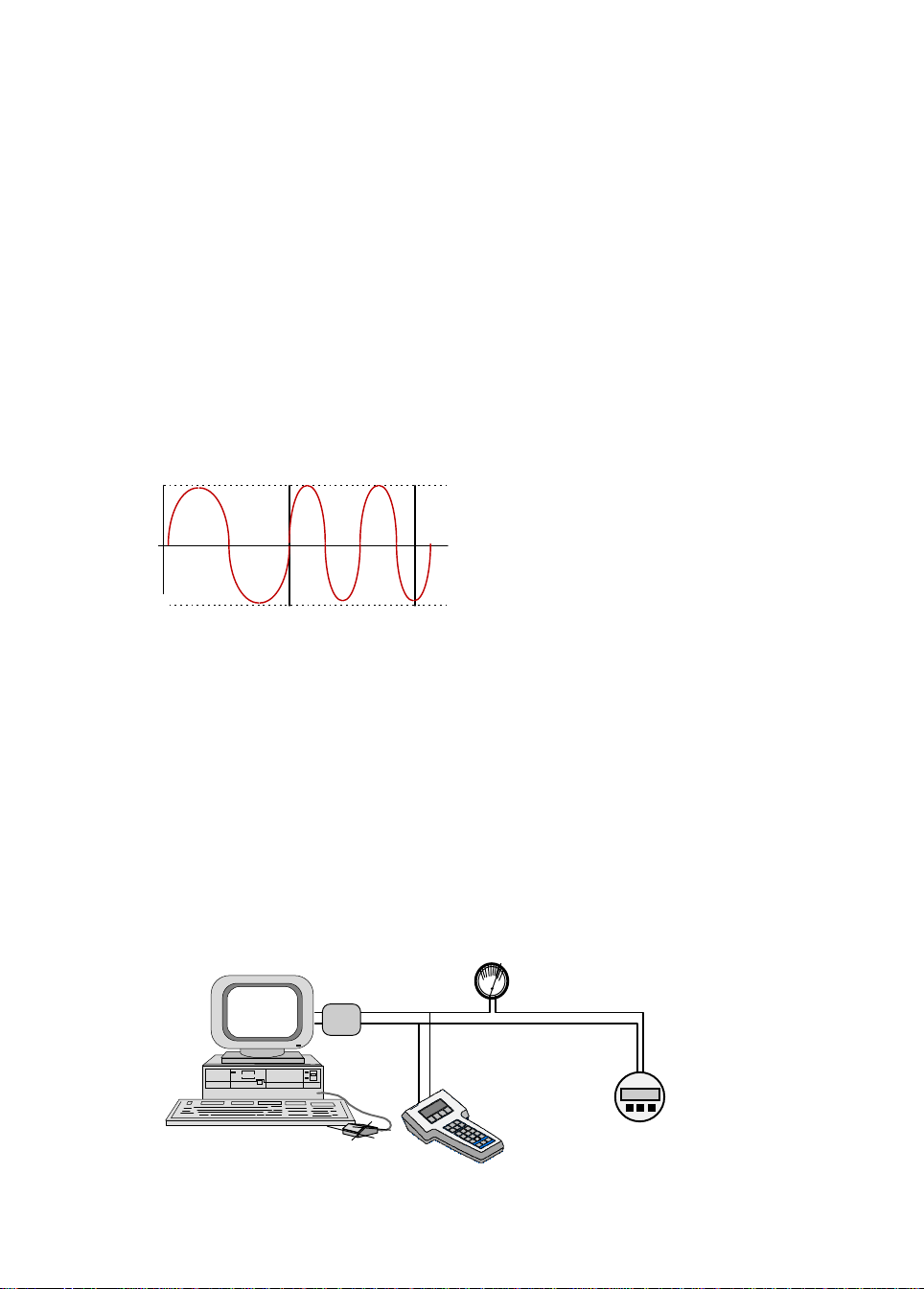
®
The HART
on the Bell 202 [1] communication standard. The digital signal is made up from two
frequencies - 1200 Hz and 2200 Hz, representing bits 1 and 0 respectively. Sine waves of
these frequencies are superimposed on the DC analog signal cables to give simultaneous
analog and digital communi cations. Because the average value of the FSK signal is always
zero, the 4 - 20 mA signal is not af f ected.
This produces genuine, simult aneous communication wit h a response time of approximately
500 ms for each field device, without interrupting any analog si gnal t ransm issi on that m i ght be
taking place.
Up to two master devices may be connected to each HART
generally a management system or a PC while the secondary one can be a hand-held terminal
or laptop com puter. A standard hand- held terminal - called the HART
available to make field operations as uniform as possible. Further networking options are
provided by gateways.
approx. +0.5 mA
protocol operates using the frequency shift keying (FSK) principl e, which is based
®
loop. The primary one is
®
Communicator - is
analog signal
approx. +0.5 mA
0
1200 Hz
“1”
2200 Hz
“0”
Simultaneous analog and digital signals
Because the mean harmonic signal value is zero, digital communi cation makes no diff erence
to any existing analog signal as demonst r ated in the figure above.
2.2 Point to point oper ation
The figure below shows some examples of point-to- point mode. The conventional 4 - 20 m A
signal continues to be used for analog transmission while measurement, adjustment and
equipment data is tr ansf erred digi t ally.
The analog signal remains unaffected and can be used for control in t he normal way. HART
®
data gives access to maintenance, diagnostic and other operational dat a.
Analog
HART
interface
Digital
mA
4
20
Up to 2 updates/sec
MFC 081/085
Multiple Masters
6
Page 7

2.3 HART
HART
the International Or gani sat ion for Standardisat i on ( ISO) [3]. The OSI model provides the
structure and elements of a communication system. The HART
®
Protocol Structure
®
follows the basic Open Systems Interconnection (O SI) r eference model, developed by
®
protocol uses a reduced OSI
model, implementing only l ayers 1,2 and 7.
OSI Reference Model
Open Systems Inte rconnecti on
Layer Function
7
6
5
4
3
2
1
Application provides formatted data HART instructions
Presentation converts data
Session handles the dialogue
Transport secures the transport
connection
Network establishes network
connections
Link establishes the data
link connection
Physical connects the equipment Bell 202
®
HART
HART protocol
regulations
The
®
protocol implements layers 1,2 and 7 from the OSI model
HART
Layer 1, the Physical layer, operates on the FSK principle, based on the Bell 202
comm uni cation standard:
Data transfer rate: 1200 bit/s
Logic ‘0’ frequency: 2200 Hz
Logic ‘1’ frequency: 1200 Hz
The vast majority of existing wiring i s used for t his type of digital communi cat ion. For short
distances, unshielded, 0.2 mm
1500 m), si ngle, shielded bundles of 0.2 mm
distances up to 3000 m can be covered using single, shielded, twisted 0.5 mm
2
two-wire lines are suitable. For l onger dist ances (up t o
2
twisted pairs can be used. Beyond this,
2
pairs.
A minimum resistance of 230 ohm s must be available in the communication ci r cuit.
Layer 2, the Link layer, establishes the format f or a HART
®
message. HART® is a
master/slave protocol . Al l the communication activiti es origi nat e from a master, e.g. a di spl ay
terminal. This addresses a field device (slave), which interprets the command message and
sends a response.
7
Page 8

The structure of these messages can be seen in the figure below. In multi-drop mode this can
accomm odat e the addresses for several field devices and terminals.
Structur e of a HART
Preamble SD AD CD BC Status Data Parity
®
message
Field device and communication
status (ONLY from field device to
master)
Byte count
HART instruction
Display termi nal and f ield device
addresses
Start character
The HART message structure offers a high degree of data integrity
A specific size of operand is required to enable the field device to carry out the HART
instruction. The byte count indi cat es the number of subsequent status and data bytes.
Layer 2 improves transmission reliability by adding the parity character derived from al l the
preceding characters; each character also receives a bit for odd parity.
The individual characters are:
1 start bit
8 data bits
1 bit for odd parity
1 stop bit
Layer 7, the Application layer, bri ngs t he HART instructi on set int o play. The master sends
messages with requests for specified values, actual values and any other data or param eters
available from the device. The field device interprets these instructions as defined in the
HART protocol. The response message provides the master with st at us i nf or mation and data
from the slave.
To make interaction between HART compatibl e devices as efficient as possible, classes of
conformi t y have been established for masters, and classes of commands for sl aves. There
are six classes of conformity f or a master as seen in the figure below.
8
Page 9

Classes of instructi on and classes of conformi ty
Read Measured
UNIVERSAL
COMMANDS
Variable
Read Universal
Information
COMMON
PRACTICE
COMMANDS
DEVICE
SPECIFIC
COMMANDS
For slave devices, logical, unifor m communication is pr ovi ded by the followi ng command sets:
Universal commands
understood by all field devices
Common pr act ice commands
provide functions which can be carried out by m any, though not all, f ield devices. Together,
these commands compr ise a library of the most common fi eld device functions.
Device-specific commands
provide functions which are restricted to an individual device, permitting special features to be
incorporated that are accessible by all users.
Write Standard
Parameters
Read Device-Specific
Information
Write Selected
Parameters
Read and Write
Entire Database
Examples of all three command sets can usually be found in a field device, including al l
universal commands, some common-practice commands and any necessary device-specific
comm ands.
2.4 Hand-held Communicator
®
A standard HART
operating instructi ons for this communicator i s not supplied by Krohne and should accompany
the hand-held communi cat or when purchased.
®
A HART
requested DDL’s already downloaded to the instrument.
The Krohne CONFIG software package can also be supplied for HART
instrum ents. The functi ons ar e similar to that described in Sect. 1.4 (available end 1996).
Further information on HART
book available on request.
The Corimass MFC 081/085 HART
require any further inform at ion, please contact your nearest Krohne office or Product
Management in Duisburg, Germ any.
Communi cat or is available from Kr ohne and m ay be purchased with all cust omer
hand-held comm unicator may be used on Krohne equipment. The
®
compatible
®
may be found in the HART® Field Comm uni cation Protocol
®
protocol is avai lable from Krohne on request. Should you
9
Page 10

10
Page 11

Krohne RS 485
Bus-Protocol
Pages 11-23
Contents
1. General 12
2. Technical Specifications 12
3. Connecti on of i nst r uments on the BUS system 13
3.1 Single Master/Slave configuration (Non Ex applicati ons onl y) 13
3.2 Single Master/Slave configuration (Ex applicati ons) 13
3.3 Multi-drop appl i cat ions 14
3.4 Bus terminati on 14
3.5 Network Biasing Resistors 15
4. Using t he Cur r ent out put with the RS 485 Bus 16
5. Convert er configuration 17
6. Transmission format 18
7. Format of the data field 18
8. Format of the data bl ocks 19
8.1 Measurement Block 19
8.2 Error list 20
9. Refer ence documentation 21
11
Page 12

1. General
The Mass flow Converter, MFC 081/085 with RS 485 interface fitted, is able t o comm unicate
with an external device (PC or other suitable computer system). This option allows data
exchange between PC or computer and singl e or multiple devices.
The Bus configuration consist s of one external device as a master and one or more converters
(MFC 081 or MFC 085) as slaves. For Bus operation the device address and baud rate must
be programmedin the m enu 3.11.0 of the MFC 081/085. Devices connected to the Bus must
have different or unique addresses and the same baud rate.
The transmission uses 8 (eight) data bits, even parity and 2 (two) stop bits at a selectable
baud rate of 1200 to 19 200.
2. Technical Specifications
Interface RS 485, potential isol at ed
Baud rate 1200, 2400, 4800,9600,19200 baud
Maximum part i cipants on Bus 32 per li ne,master included (may be extended by repeaters)
Coding NRZ bit coding
Address range 0 - 239
Transmission procedure half duplex, asynchronous
Bus access master/slave
Protocol Krohne RS 485 Communicati on Bus Protocol
(Available as a separate instruction document on request)
Cable screened twisted pair cable
Distances maximum 1.2 km without repeater.
(Dependant on baud rate and cable specifications)
Technical data of the RS 485 int er f ace (according to EIA standards)
Kind of signal tr ansmission: differential
Maximum number of transmit ter/receivers: 32
Maximum vol t age on driver output : –7 V to +12 V
Minimum voltage on driver output, max.load: U dif f > 1, 5 V
Maximum i nput cur r ent (of f st at e) –20 to +20 • A
Receiver input voltage –7 V to +12 V
Sensitivity of the receiver –200 mV to +200 m V
Receiver input resistance > 12 k ohm
Short circuit cur r ent of t r ansmission < 250 mA
12
Page 13

3. Connecti on of i nst r uments on the Bus system
The following termi nals are used in the MFC 081/085 converters for the signal receive (Rx),
transmi ssi on ( Tx) and ground.
3.1 Single Mast er /Slave configurati on ( Non Ex appl ications only)
MFC 081/085
rear terminal
Screened twisted pair cable
TX/RX
compartment
4.1 TX+/RX+
120R 120R
TX/RX
Terminati ng
screen
4 TX-/RX-
Resistor
Fig. 1
Notes:
1. Terminating r esistor s to be used at both ends.
2. Terminating resistors to be mounted externally between terminals 4 and 4.1 if not
internally connected.
3. For Ex instrum ents the termi nating resistors must be internally connected. (See section
below).
3.2 Single Mast er / Sl ave conf i gur at ion (Ex applications)
For Ex instrum ents the terminati on resistor has to be inside the pressure tight section of the
housing. A terminating resistor is already supplied on the RS 485 module and only needs to
be enabled by soldering the two solder pads together (Fig. 2) or enabling the jum per which i s
supplied on modules of a later design. (Fig. 3)
Solder pads to
RS 485
be joined
Module
RS 485
Module
Fig. 2
Fig. 3
S1
90° Pin header
Shorting link
OFF
ON
Termination
Termination
13
Page 14

3.3 Multi-drop applicati ons
y
RS 485 allows mult i ple instruments to be connected in half duplex on a si ngle twisted wire pair
for “party line” type of communications. A method must be used to stop more than one
instrument being online at any time, ensuring that all other instruments are in a high
impedance state. No damage is done when more than one instrument is online
simultaneously, but data will be lost.
In a mult iple RS 485 transmit t er inst allation, the application program controls the bi-dir ecti onal
data communication and selects the instrum ent to be addressed.
The program control used should be a “master/slave” method. The “master/slave” method
designates one device on the network as master, and t his device supervises all transmi ssions
by comm uni cating with each of the slaves in turn and offering it a transmission slot.
3.4 Bus terminat ion
For proper operation of the RS 485 Bus in half duplex mode in single or multi-drop
comm unicati on, it is recomm ended that a terminat ion resistor (typi call y 120 ohm ) i s appli ed to
both ends of the data line. The simplest form of term ination i s li ne to li ne resistor acr oss the
differential input.
In a multi-drop system, the terminator resistors are only required at the ends of the bus,
usually the master and the last device on the line. The devices in-between do not require
termination.
The Bus configurations are shown in Fig. 4 and Fig. 5.
Configuration with single slave:
stem
Bus S
Screened twisted pai r
Computer System RS 485 Connection
terminated with 120
ohm resistor between
two lines - RX/TX
Fig. 4
Slave
MFC 081/085
Terminating resistor
(120 ohm) between
terminals 4 and 4.1
14
Page 15

Configuration with multi pl e slaves:
q
Terminating resistor
required
Compu ter S yst em
Terminating
resistor
uired
re
Slave Slave Slave Slave
No terminating r esistors required
Fig. 5
Please note: If other instruments are to operate on the same Bus, all the devices must use t he
same comm unication protocol.
To avoid interfering signal reflections from the ends of the Bus line, both ends ( at computer
system as well as at the last inst rument) should be term inated with the typical li ne resistance
value of 120 ohm.
3.5 Network Biasing Resistors
In RS 485 multi-drop operation, noise may be detected at the master. In a multi-drop
configurati on there can be brief periods when no instrument is enabled or addressed, and the
network is therefore allowed to float. Some devices on the network may then be susceptibl e t o
noise and may be liable to fl oat t o a pot enti al t hat is detected as an input.
If this problem is encountered, two extra resistors can be added externally to one end of the
Bus, so that the network is biased to a value of approximately 1 Volt when all devices are
disabled. For non-Ex systems, resistors coul d be added to the last MFC 081/085 device as
shown in Fig. 6 or to t he Master (PC).
MFC 081/085
converter
4.2 + 5 V
TX/RX
120R
390R
4.1 TX+/RX+
150R
4 TX/RX
TX/RX
Screened twisted pair c able
390R
5. OV
Biasing resistors of
390 ohm
Fig. 6
However, for Ex systems, adding resistors wit hin the terminal com partment is not allowed as
this would contravene the Ex requirements. In this case the biasing resistors shoul d be added
at the Master’s end of the bus, provided it is located in a safe area.
15
Page 16

4. Using t he Curr ent O ut put with the RS 485 Bus
The MFC 081/085 Converter is fitted with one current output in addition to the RS 485
connection. This current loop is connected between termi nals 6, lout, and 5, 0 volts (refer to
the normal Installation and Operating manual). However extra care must be taken when
connecting this output.
The MFC 081/085 output circuitr y is fully floati ng. It is galvanically isolated from protective
earth, PE and from the converter’s power supply. (See below).
Terminating and
biasing resistors
If just the RS 485 bus is connected then the converter’s output circuitry will float to the
potential of the bus. However the current output shares a com mon 0 volt r eference with t he
RS 485 output and hence also with the bus. The current loop receiver m ust therefor e have
a fully floati ng input. If not it will try to drag the RS 485 bus to som e potential of its own.
This could in tur n result in interference with stable operation of either, or both of t he current
loop and the RS 485 bus.
16
Page 17

5. Convert er Configuration
–
–
Setting up the RS 485 System:
Use the 3.11.0 Serial I/O m enu to set up the RS 485 communications:
Fct. 3.11.0 Serial I/O
Fct. 3.11.1 Prot ocol
Select OFF to disable
comm uni cat ions or “KROHNE”
to use the Krohne Bus Protocol.
Fct. 3.11.2 Address
Enter an address number
between 0 and 239. The
converter will only respond to
Bus messages which have a
matching addr ess.
Fct. 3.11.3 Baudrat e
Select the required
comm uni cations baudrate from
the following list:
1200, 2400, 4800, 9600, 19200
If the instrument is connected correctly, it should now communicate with an external master.
6. Transmission format
The data string has the followi ng f or mat:
syn ... syn STX < Data-Field > CS ETX
The transmission is initiat ed through an arbitrary num ber (at least 3) of Synchronisat ion bytes.
(Syn hex 16). This initialises the receiver to receive a data string. The string it self begins with
a start byte (STX, Hex 16) followed by the data field. The transm ission is concluded with a
verification sum (Check sum, CS) and the end byte (ETX Hex 3).
The checksum byte is the sum [module 256 of all the bytes in the bus telegram (including
STX)] plus the number of bytes.
If one of the control characters (Syn, STX, ETX) appears in the data fi eld or in the check sum,
then the symbol DLE (Hex 10) is placed in front of it. This is tr ue for the sym bol DLE it self.
These intentional prefix symbols are not entered in the check sum.
Examples (all values in hex code):
16 – 16 – 16 – 02 – AO
01 – 6F – 07 – 1E–03
Syn Syn Syn STX DEV ADR VER FKT CS ETX
16 – 16 – 16 – 02 – AO
m
SynmSynmSTX DEV DLE ADR VER FKT CS ETX
Syn
10–03–6F–07–20–03
Address 03 represented as DL03
DLE is not included in checksum calcul at ion
17
Page 18

7. Format of the data field
The data field format f or Bus tr ansmission is as follows:
DEV ADR VER FKT < Paramet e r - Field >
The device code byte (DEV) recognises the unique code assigned to the particular type of
KROHNE device connected to the Bus. For MFC 085 this code is OAO hex, and OA1 for the
MFC 081.
The address byte (ADR) contains the bus address of the requested device. Values from 0 t o
239 (0 hex to 0EF hex) are permissible. Addresses 240 to 255 are reserved for special
functions.
The version byte (VER) is relevant only for acknowledgement purposes. In a
acknowledgement request it may be set to an arbitrary value. This fi eld is a composite one:
bits 5 - 7 define the version number of the device software, bits 0 - 4 subversion num ber, e.g.
a device with version 3.15 Software will acknowledge in VER field as 6F hex.
The function byte (FKT), like the VER byte, is also spli t into two fields: bits 5 - 7 define a
generalised function which will later on be referred to as Function, while bits 0 - 5 define
additional identification information being either a logical address of a device data block or
descriptor of a special request to device (like calibrati on, quit errors, etc.). These latter 5 bit s
will later be referred to as Subfunction. For complete list of FKT-driven functionality refer to
the Function Byte Codes table in the protocol manual.
Device response time depends on requested operation:
• Read measurement block ≈ 20 msec
• Read single static block ≈ 5 msec
• Write single block ≈ 200 msec
• Write two blocks ≈ 400 msec
In a case where a special operation is requested that deals with com plete device reset, busconnection will be lost until the instrument bypass re-initialisation.
18
Page 19

8. Format of the Data Blocks
8.1 Measurement Block, Function Code ( FKT) = O O Hex
Offset Variable/ For mat Length M eaning
0 drive_level
2 Installation fact or
(int, LSB first)
2 mass_flow_rate_LPF
4 Mass fl ow in g/ sec
(float, inversed IEEE 754)
6 master_total
8 Mass totalizer in g
(double, LSB first)
14/0E hex volume_total
4 Volume totalizer in cm
(float, inversed IEEE 754)
18/12 hex tube_temperatur e
2 Temperature in °C × 10
(int, LSB first)
20/14 hex st r ai n
2 Str ain gauge in Ω × 20
(int, LSB first)
22/16 hex fr equency
4 Resonant frequency in Hz
(float, inversed IEEE 754)
26/1A density_LPF
4 Fluid density in g/cm
(float, inversed IEEE 754)
30/1E hex zeroadj_flow_LPF
(float, inversed IEEE 754)
34/22 hex phase
(float, inversed IEEE 754)
38/26 hex percentage_by_vol
float, inversed IEEE 754)
4 Mass fl ow in g/ sec. Vali d dur ing zero
calibrations
4 Raw sensor phase in radians. Used for
debug purposes.
4 Valid only for General Concentration
option.
Units: 0.01% (thus a value of 1.0
corresponds to 100%)
42/2A hex percentage_by_mass
(float, inversed IEEE 754)
4 Valid if any concentration opt ion is
active.
Units: 0.01 of concentrati on unit related
to option.
i.e. a value of 1.0 corresponds to:
100% for General Concentration
100°Brix for Brix Concentration
100°Baumé for Baumé Concentration
46/2E hex solid_flow_r at e
(float, inversed IEEE 754)
50/32 hex sum_angle
4 Valid if any Concentration option is
active in g/sec.
4 Used for debug purposes
(float, inversed IEEE 754)
54/36 hex converter_status (byt e) 4 Refer to
actual_errors
(section 7.2)
58/3A hex system_state (byte) 1 Instrument state
1 - Stop 2 - Startup
3 - Measurement 5 - Standby
6 - Calibration
59/3B hex r1
4 Used for m aintenance service
(float, inversed IEEE 754)
63/3F hex r2
4 Used by mai nt enance service
(floa t , inversed IEEE 754
67/43 hex reserved 8
3
3
field of Error list
19
Page 20

8.2 Error list, Function Code (FKT) = O A Hex
Offset Variable/Format Length Meaning
0 actual_errors
(long, LSB
first)
4 Actual error messages:
Bit 0 : Mass Flow (Measured flow > 2 nominal f l ows of
primar y head
Bit 1 : Zero Error (Excessive flow measured during zero
calibration
Bit 2 : Totalizer Overflow (Fixed precision totalizer has
rolled over)
Bit 3 : Frequency
Bit 4 : Temperature (measured temperature > 180°C or
< –25°C
Bit 5 : Sensor A OOR (Sensor A signal too small)
Bit 6 : Sensor B OOR (Sensor B signal too small)
Bit 7 : Ratio A/B (One sensor signal much bigger than
the other
Bit 8 : DC A (Sensor A has a large DC offset)
Bit 9 : DC B (Sensor B has a large DC offset)
Bit 10 : Temperature AC
Bit 11 : Sam pl ing (No synchronisation wit h pr i mary head
oscillations)
Bit 12 : Not used
Bit 13 : ROM Default ( EEPRO M checksum error detected
on power up)
Bit 14 : Not used
Bit 15 : EEPROM (Unable to save data into EEPRO M
chip)
Bit 16 : NVRAM (Checksum error detected in NVRAM on
power up)
Bit 17 : NVRAM Cycles (NVRAM chip has had > 10000
save cycles)
Bit 18 : Power Failure -Main supply has been switched off
Bit 19 : Watchdog (System has been rebooted by
WATCHDOG chip)
Bit 20 : System (Software has got into an illegal state)
Bit 21 : Temp.Custody (Temp. drifted ±30°C from zero
calibration temp.)
Bit 22 : Strai n O OR (Measured strain out of range)
Bit 23 : Current 1 (Measured quantity outside range limits
for the output)
Bit 24 : U36 (Measured quantity outside range limits for
the output)
Bit 25 : Process Alarm ( Measured quantity exceeded user
defined limit s)
Bits 26 - 31 : Not used
4 stored_errors
(long, LSB
4 Stored error messages
For bits layout refer to
actual_errors
first)
Any actual_error becomes a
be cleared via special request.
stored_error
when t h e reas on s t hat c aus ed it d is ap pear . O nl y
stored_errors
may
20
Page 21

9. Refer e nce documentation
If any problems are encountered, please contact your nearest Krohne office or representative
or contact Product management at Krohne Duisburg - Germ any.
Further documentation available as follows:
a) Krohne Massflow Install at i on and Operating manual:
MFM 2081 K / MFM 3081 K P- and E-Series with MFC 081 Converter
MFM 4085 K G-Series with MFC 085 Converter
b) Krohne application Engineering Release
Krohne Communicat ion Protocol - Com munication wi t h Kr ohne Bus Protocol.
These documents are available from Product management on request.
The following is also available for furt her soft ware development:
a) A simple PC test program to excercise the RS 485 Bus.
b) ”C” Source code for the RS 485 protocol to help custom ers with software development.
21
Page 22

22
Page 23

Modbus
Protocol
Version: 1.0
Applies to Software Versions P 2.22 (M FC081) & G 3.00 (MFC085)
and above
Pages 23-35
Contents
1. General 24
2. Technical Specifications 24
3. Connecti on of i nst r uments on the Bus system 25
3.1 Network Terminating and Biasing Resistors 26
4. Usi ng t he Cur r ent output with Modbus 27
5. Convert e r conf iguration 27
6.0 Modbus Protocol 28
6.1 RTU Frame Format 28
6.2 Function Codes 29
6.3 Data Formats 30
6.4 Addresses Allocation 30
6.5 Register Addresses 31
6.6 Error Return codes 33
6.7 Diagnostic Codes 34
7.0 Refer ence Documentation 35
23
Page 24

1. General
The Mass flow Converter, MFC 081/085 with Modbus/RS 485 interface fitted, is able to
communicate with an external device (PC or other suitable computer system) using the
Modbus protocol. This opt ion allows data exchange between PC or com puter and single or
multiple devices.
The Bus configuration consist s of one external device as a master and one or more converters
(MFC 081 or MFC 085) as slaves. For Bus operation the device address and baud rate must
be programmed in the menu 3.11.0 of the MFC 081/085. Devices connected to the Bus must
have different unique addresses and the same baud rate and settings.
The transmission uses 8 (eight) data bi ts, even or odd parity and 1(one) or 2 (t wo) stop bit s at
a selectable baud rate of 1200 to 19200.
2. Technical Specifications
Interface RS 485, galvanically i s ol at ed
Baud rate 1200, 2400, 4800, 9600, 19200 baud
Protocol Modbus RTU
(Available as a separate document on
request)
Maximum part i cipants on Bus 32 per li ne, master included (may be
extended by repeaters)
Coding NRZ bit coding
Address range Modbus: 1 – 247
Transmission procedure half duplex, asynchronous
Bus access master/slave
Cable screened twisted pair cable
Distances maximum 1.2 km without repeater.
(Dependant on baud rate and cable
specifications)
Technical data of t he Modbus interface ( accor ding to EIA standards)
Kind of signal tr ansmission: Differential
Maximum number of transmit ter/receivers: 32
Maximum vol t age on driver output : –7 V to +12 V
Minimum voltage on driver output, max.load: U dif f > 1, 5 V
Maximum i nput cur r ent (of f st at e) –20 µA to +20 µA
Receiver input voltage –7 V to +12 V
Sensitivity of the receiver –200 mV to +200 m V
Receiver input resistance > 12 k ohm
Short circuit cur r ent of t r ansmission < 250 mA
24
Page 25

3. Connecti on of i nst r uments on the Bus system
The Bus configurations are shown in Fig. 1 and Fig. 2.
Configuration with single slave:
Bus System
Screened twisted pair
Computer System
Modbus Connection
with termination and
biasing resistors.
Fig. 1
Configuration with multi pl e slaves:
Terminating and biasing
resistors
Slave
MFC 081/085 with
Terminating resistor
Computer System
No terminating resistors required
on intermediate slaves
Terminating
resistor
required
Fig. 2
Please note: If other instruments are to operate on the same Bus, all the devices must use t he
same comm unication protocol.
25
Page 26

3.1 Bus terminat i on and Bi asi ng Resi st er s
For proper operation of Modbus in half duplex mode in single or mul ti-dr op comm unicati on, i t
is recommended that a termination resistor (typical ly 120 ohm) is appl ied to both ends of the
data line. The simplest for m of termi nation is line to li ne resistor acr oss t he diff erential i nput.
In RTU mode the Modus protocol requires quite periods on the communications bus for
synchronisation. It is therefore important that the Modbus is not allowed to ‘float’, i.e.
unreferenced to 0V, as this coul d lead to spurious signal s due to noise pick-up. It is therefore
necessary to employ biasing resistors at one point on t he bus network as shown in figur e 3.
MFC 081/085
converter
4.2 (+5 V)
TX/RX
120R
TX/RX
Screened twisted pair cable
390R
4.1 (TX+/RX+)=B
150R
4 (TX-/RX-)=A
390R
5. (OV)
Fig. 3
For Ex instrum ents the terminati on resistor has to be inside the pressure tight section of the
housing or other suitable enclosure. For convenience terminat ing and biasing r esistors ar e
already supplied on the RS 485/Modbus module. These can be enabled by soldering the two
solder pads together
(Fig. 3) or enabli ng t he jumper which is supplied on modules of a later design. (Fig. 4).
26
RS 485
Module
RS 485
Module
Fig. 4
Fig. 5
Solder pads
to be joined
S1
90° Pin header
Shorting link
OFF
ON
Termination
Termination
Page 27

4. Usi ng t he Cur r ent Output with t he Modbus
The MFC 081/085 Converter is fitted with one current output in addition to the Modbus
connection. This current loop is connected between termi nals 6, lout, and 5, 0 volts (refer to
the normal Installation and Operating manual). However extra care must be taken when
connecting this output.
The MFC 081/085 output circuitr y is fully floati ng. It is galvanically isolated from protective
earth, PE and from the converter’s power supply. (See below).
Terminating and
biasing resistors
If just the Modbus is connected then the converter’s output circuit ry will float to the potential of
the bus. However the current output shares a common 0 volt reference with the Modbus
output and hence also with the bus. The current loop receiver m ust ther efore have a f ully
floating i nput. If not it will try to drag the Modbus to some potential of it s own. This coul d i n
turn result in i nterference with stable operation of either, or both of t he current loop and t he
Modbus.
5. Convert er Configuration
Setting up the Modbus System:
Use the 3.11.0 Serial I/O menu to set up the Modbus comm uni cat ions:
Fct. 3.11.0 Serial I/O
Fct. 3.11.1 Prot ocol
Select “MODBUS”
Fct. 3.11.2 Address
Enter an address number between 1 and
247. The converter will only respond to
Bus messages which have a matching
address.
Fct. 3.11.3 Baudrat e
Select the required communications
baudrate from t he following list:
1200, 2400, 4800, 9600, 19200 and the
data form at f rom
E81,E82,O81,O82, N81,N82.
N=no parity: E=even parity: O=odd parit y
1 or 2 stop bits
27
Page 28

If the instrument is connected correctly, it should now communicate with an external master.
Please note, that all devices on the bus (including the master) must be set to the same
comm uni cations protocol, baudr ate and format, but wi t h a different address.
6. Modbus Protocol
Using RTU (Remote Terminal Unit) format, data is transmitted as 8 bit binary characters.
There are no special characters to determine the start and end of a message frame,
synchronization is achieved by a mini mum silent period of at least 3.5 character ti mes before
the start of each frame transmission and a maximum silent period of 1.5 character times
between characters in the same frame.
6.1 RTU Frame Format
The format of the Query and Response frames vary slightly depending upon the command
function. The basic for m is outlined below.
Silent
Period
3.5 T 8 bits 8 bits 8 bit byte count
Slave
Address
Function
Code
Register Start Address
or
Byte Count when
required
No.of.Points
or
Data bytes
when required
n x 8 bits 16 bit s
CRC
16 bit address
Silent peri od.
All transmissions must be preceded by a minim um silent period of 3.5 x T, where T is the
transmi ssion ti m e of a single character. Thi s can be calculated from the baud rate e.g. at 19.2
Kb no parity with 1 st op bi t (10 bits), T= 520 us.
Slave Address.
This is a single byte slave address which is transmi tted first and m ust be in the range of 1-
247. Address 0 is reserved for a broadcast address which al l slaves should recognize, and
therefore requires no response.
Function Code.
This is an eight bit code in the range of 1-255 although onl y 126 f unctions exist as the codes
129-255 represent an error condition. An error condition occurs when the addressed slave
does not accept the command, in which case it r esponds with t he functi on code + 128, i. e. wit h
its MSB set to 1.
Byte Count.
In general this is only pr esent in frames that are transferring dat a, and has a value equal to the
number of bytes contained in the data fi eld.
The data field is limited to a maximum of 250 byt es
Register Start Address
For a Query comm and that requires data to be r eturned, this field w ill contain the 16 bit start
address of the register (or data) to be returned.
Number of Points.
For a Query comm and that requires data to be returned, this fi eld will contain the number of
registers to be returned regardless of their bit size.
CRC
This fi eld co nta ins a 16 bi t CRC whic h i s cal cul at ed on al l t he da ta bi ts o f th e m essage b ytes.
28
Page 29

6.2 Function Codes
Table 1 shows the function codes and data types supported by the MFC081/085. All data
types occupy one holding register location. This i s achi eved by storing the address index of the
data in the holding registers. However, this is invi sibl e to the user who should access r egister
data in the normal way.
Table 1. Supported ModBus codes.
Register
Address
Function
Codes
(hex)
00000-
01
0000F
05
20010-
03
2004F
16
40050-
03
4006F
06
16
A0070-
03
A008F
06
16
B0090-
03
B009F
16
R=read, W=wri te.
Data
Access Description
Type
bit RWRead On/Off status of st at us/control
bit. (8 bit s bl ocks per read)
Force Single control bit.
float RWRead multiple registers. Read 2
registers for each float.
Write multipl e registers. Write 2 16bit
registers for each float.
int R
Read multiple registers. Reads 1
register per integer.
W
Write single register / integer.
W
Write multiple registers/integers
byte R
Read multiple registers. Read 1 byte
per register.
W
Write single byte.
W
Write multiple bytes
double RWRead multiple registers. Read 4
registers for each double.
Write multiple registers. Write 4
registers for each double .
29
Page 30

6.3 Data Formats
Table 2. Integers
15-8 High byte
Table 3. Single Precision Floati ng Poi nt .
Bits
7-0 Low byte
Bits Bit or der
Mnemonic
MSB - LSB
Bits 32- 2 4 SEEEEEEE S/E
Bits 23-16 EMMMMMMM E/ M1
Bits 15-8 MMMMMMMM M2
Bits 7-0 MMMMMMMM M3
Table 4. Double precision floati ng Poi nt .
Bits Bit or der
Mnem oni c
MSB - LSB
Bits 63- 5 6 SEEEEEEE S/E
Bits 55 -48 EEEEMMMM E/M1
Bits 47-40 MMMMMMMM M2
Bits 39-32 MMMMMMMM M3
Bits 32-24 MMMMMMMM M4
Bits 23-16 MMMMMMMM M5
Bits 15-8 MMMMMMMM M6
Bits 7-0 MMMMMMMM M7
S = sign bit E = exponent M = mantissa
Table 5. Transmission Order
Transmissi on
order/type
1st
byte
Last
byte
Bits see
4.2.1
Bytes 0 Low
Integers High Low
Float M2 M1 S/E E/M1
Double M6 M7 M4 M5 M2 M3 S/E E/M1
6.4 Addresses Allocation
The following table shows the supported data types and their address block allocation
Address Range Type
0xxxx Bit (Descrete Ou tputs)
1xxxx
2xxxx Float ( Wo rd sw apped)
3xxxx Integer ( Input Registers)
4xxxx
30
Page 31

5xxxx
6xxxx
7xxxx
8xxxx
9xxxx
Axxxx Byte
Bxxxx Double (Word swapped)
6.5 Register Addresses
Address Description Units/Value
Access
Menu Ref.
Hex (Decimal ) Bit registers
0000/0000 Update configuration data Save cha nges in
R/W
EEPROM
0001/0001 Begin zero flow calibration - R/W 3.1.1
0002/0002 Reset totals - R/W
0003/0003 Switch to standby mode - R/W 3.1.4
0004/0004 Switch to measure mode - R/W 3.1.4
Float registers
0010/0016 Mass flow rate g/s R
0011/0017 Volume flow rate cm3/s R
0012/0018 Volume tota l cm
3
R
0013/0019 % volume flow rate % R
0014/0020 % mass flow rate % R
0015/0021 Solid flow rate g/s R
0016/0022 Density g/cm
0017/0023 Referred density g/cm
0018/0024 Solute density g/cm
0019/0025 Solute k1 constant
001A/0026 Solute k2 constant
001B/0027 Liquid density g/cm
001C/0028 Liquid k1 constant
001D/0029 Liquid k2 constant
001E/0030 Reference temperature
001F/0031 Reference de nsity slo pe - RW
0020/0032 Fixed de nsity g/cm
g/cm
g/cm
g/cm
g/cm
x10 °C
3
/ °C
3
/ °C
3
/ °C
3
/ °C
3
3
3
2
3
2
R
R
R 3.10.1
RW 3.10.2
RW 3.10.3
RW 3.10.4
RW 3.10.5
RW 3.10.6
RW
3
RW
0021/0033 Head constant - R 3.1.6
0022/0034 (G) Density coefficient CF1
(P&E) Water calibration
-
50-200 Hz
R
R
3.9.1
3.9.1
reference frequency
0023/0035 (G) Density coefficient CF2
(P&E) Air calibration
reference frequency
0024/0036 (G) Reference strain CF3
-
R
R
50-200 Hz
-RR3.9.3
3.9.2
3.10.3.
(P&E) Temperature constant
0025/0037 (G) Reference Temp. CF4
-RR3.9.4
(P&E) Frequency constan t
0026/0038 Zero flow cutoff % of nominal R 3.1.2
0027/0039 Low flow threshold % of full scale x 10 RW 3.1.1
0028/0040 Frequency Hz R 2.7.3
0029/0041 Maximum trigger value as base unit RW 3.7.4
002A/0042 Minimum trigger value as base unit RW 3.7.3
Integer registers
003C/0060 Measurement time-constant x10 s R/W 3.1.3
003D/0061 Drive level - R
003E/0062 Strain ohms x 20 R
31
Page 32

003F/0063 Tube temperature (x10)
x10 °C
0040/0064 Sensor A average level - R
0041/0065 Sensor B average level - R
R
Byte registers
005A/0090 Mass flow display units note
005B/0091 Mass flow display format note
005C/0092 Mass total display units note
005D/0093 Mass total display format note
005E/0094 Volume flow display units note
005F/0095 Volume flow displa y format note
0060/0096 Volume total display units note
0061/0097 Volume total display format note
0062/0098 Density display units note
0063/0099 Density display format note
0064/0100 Solid flow display units
0065/0101 Solid flow display format
1
1
0066/0102 Temperature units note
0067/0103 Concentration by mass
display format
0068/0104 Concentration by volume
display format
0069/0105 Density mode
1
1
2
1= actual
note
note
3
3
3
3
3
3
3
3
3
3
3
3
3
RW 3.2.3
RW 3.2.3
RW 3.3.4
RW 3.3.4
RW 3.2.7
RW 3.2.7
RW 3.2.8
RW 3.2.8
RW 3.2.5
RW 3.2.5
RW 3.2.9
RW 3.2.9
RW 3.2.6
% RW 3.2.10
% RW 3.2.11
RW 3.2.5
2=fixed
3=referred
006A/0106 Concentration function 1=none
RW 5.5.4
2=brix
3=general
4=baume 1443
5=baume 1450
6=NaOH
7=Referred Density
006B/0107 Transducer Model 1 = 10G
R 3.1.5
2 = 100G
3 = 300G
4 = 800G
5 = 1500G
6 = 3000G
006C/0108 Transducer Materia l/type 0=Titanium G-
R 3.1.5
Classic
1=Titanium G+
2=Zirconium GClassic
3=Zirconium G+
006D/0108 Software version - R 5.1.5
006E/0109 Software sub-version - R 5.1.5
006F/0110 System state 1 = Initialisation
R 3.1.4
2 = startup
3 = measure
5 = standby
6 = zero adjust
0070/0111 Flow direction 1=forward
R 3.1.7
2=backwards
0071/0112 Flow mode 1=positive
R 3.1.8
2=negativ e
0072/0113 Control function 1=off
R 3.7.1
2=force flow to zero
3=zero flow and
totalisers
4=disable o/p
0073/0114 Control condition R
0074/0115 Language 1 = Deutsch R 3.8.0
32
Page 33

2 = English
3 = French
0075/0116 Liquid type 1=water
Double registers
0083/0131 Mass Total g R
1
. Only avail able when concentration m easurement inst al led.
2
. Only avail able when concentration set to referred density
3
. For display f or mat this i ndicates number of digits af t er the decimal point and is in t he range
2=non-wate r
RW
0-7. Bit 4 is set if the measurement is enabled.
For display unit s the byte is divi ded into a high and l ow ni bble. Each nibbl e indi cates t he units
type depending on the measurement as shown in the following table.
1grams
2 kilograms
°C
°F
seconds cm
minutes dm
3 tonnes hours Litres
4 ounces days m
5 pounds in
6 Specific Gravity ft
3
3
3
3
3
7 US gallons
8 Gallons
6.6 Error return codes
In the event of a command not being com pleted, the following error codes may be returned.
1 Function code not allowed
2 I l legal data address
3 I l legal data value
4 Slave device failure
5 Acknowledge - extended time required
6 Slave device busy
7 Failed to carry out request
8 Request to change value refused
9 Custody l ocked
33
Page 34

6.7 Diagnostic codes
These are related to the Modbus comm and 08.
Sub
command
0 Echo Query command
1 Restart communcations
2 Return 16bit status r egister
3 Not supported
4 Turn off communicat i ons
5 Not supported
6 Not supported
7 Not supported
8 Not supported
9 Not supported
10 Clear event lo g
11 Return bus message count
12 Return CRC erro r c ount
13 Return Exception count
14 Return Slave message count
15 Return No response count
16 Return NAK count
17 Return SlaveBusy count
18 Return Communications Overrun
count
1
. These commands do not return a r esponse.
2
. Status Register
Description
1
2
1
Bit No Meaning
00 Zero Error - Excessive flow measured during zero calibration.
01 Temperature m easured > 180 C or < -25 C.
02 Sensor A out of range.
03 Sensor B out of range.
04 Ratio of sensors A/B exception. One sensor reading is >> than other.
05 Sensor A has a large DC offset.
06 Sensor B has a large DC offset.
07 No synchronization with primary head oscillations.
08 ROM checksum error detected on power-up.
09 EEPRO M s av e erro r .
10 Non Volati l e RAM checksum error detected on power-up
11 Power Failure recorded.
12 Watchdog System Reboot has been activated.
13 Software exception registered.
14 Temperature drifted +/- 30 C from zero calibr at i on temperature.
15 Current Loop measurement Out of Range.
34
Page 35

7. Refer e nce documentation
If any problems are encountered, please contact your nearest Krohne office or representative
or contact Product management at Krohne Duisburg - Germ any.
Further documentation available as follows:
a) Krohne Massflow Installat ion and Operating manual :
MFM 2081 K / MFM 3081 KP- and E-Series with MFC 081 Converter
MFM 4085 K G-Series with MFC 085 Converter
b) Krohne applicati on Engi neering Release: Modbus Protocol.
These documents are available from Product management on request.
The following is also available for furt her soft ware development:
a) A simple PC test program to exercise the RS 485 Modbus.
b) ”C” Source code for the Modbus protocol to help custom ers wit h sof t ware development.
35
 Loading...