

Page 1
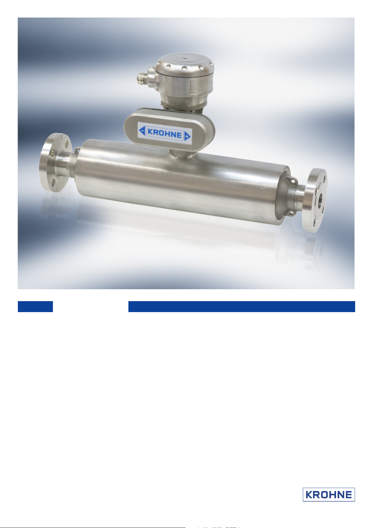
OPTIMASS
MFC 010 Converter
•• FFoorr bbootthh OOPPTTIIMMAASSSS aanndd OOPPTTIIGGAASS fflloowwmmeetteerrss
•• FFoorr ddiirreecctt mmeeaassuurreemmeenntt ooff mmaassss ffllooww rraattee,, ddeennssiittyy aanndd pprroodduucctt tteemmppeerraattuurree
•• MMOODDBBUUSS pprroottooccooll
•• SSooffttwwaarree vveerrssiioonn 22..33..xx
Page 2

Page 3

1
Contents
1. Introduction 5
2. Mechanical Installation 5
3. Electrical Installation 6
3.1 Electrical Input Specifications for the MFC010 6
3.2 Recommended Cable Specification 7
3.3 Connection to the MFC010 8
3.4 Connection to the Modbus Bus 10
3.5 Installation Guidelines for Electromagnetic Compatibility 12
4. Installation in Hazar d o u s Area Applications 13
4.1 Power Supply Barrier Devices 15
4.2 Modbus Barrier Devices 16
4.3 Connection To The Modbus Bus 17
5. Modbus Protocol Interface 19
5.1 Character Transmission Format 19
5.2 Modbus Telegram Format 20
5.3 Data Types in Modbus 20
5.4 Multidrop Operation 21
5.5 Calculating Data Transmission Rates 21
5.6 Error Messages in Modbus 22
6. Modbus Functions Supported by the MFC010 23
6.1 01 (0116): Read Coil Status 23
6.2 02 (0216): Read Discrete Input 24
6.3 03 (0316): Read Holding Registers 25
6.4 04 (0416): Read Input Registers 26
6.5 05 (0516): Force Single Coil 27
6.6 06 (0616): Preset Single Register 28
6.7 07 (0716): Read Exception Status 29
6.8 08 (0816): Diagnostics 30
6.9 11
6.10 16
(0B
): Fetch Comm. Event Counter 30
16
(10
): Preset Multiple Registers 31
16
6.11 17 (1116): Report Slave ID 32
7. MFC010 Modbus Data Model 33
7.1 MFC010 Register Structure 33
7.2 Discrete Status Output “Coil” Registers 39
7.3 Discrete Input (Binary) Status Registers 41
7.4 Input Registers 43
7.5 Holding Registers 49
8. MFC010 Operations 71
8.1 Mass Flow Zero Calibration 71
8.2 Density Calibration 72
8.3 Fixed and Referred Density Operation 75
8.4 Concentration Measurement 76
8.5 Using the System Protection Passwords 76
8.6 Saving and Restoring Configuration settings 77
8.7 Implementing User Defined Units 77
8.8 Using the Internal Process Control Mechanism 78
8.9 Custody Transfer Applications 78
8.10 Pressure Suppression 79
MFC010 Interface Manual
Page 4

2
MFC010 Interface Manual
9. Error and Warning Messages 81
9.1 System Errors 81
9.2 Process Warnings 85
10. Trouble Shooting 88
10.1 “No Response to Modbus Requests” 88
10.2 “Communication Errors” 88
10.3 “The MFC010 is responding with an Illegal Modbus Function Message” 89
10.4 “The MFC010 is responding with an Illegal Data Message” 89
10.5 “The MFC010 is responding with an Illegal Address Message” 89
Appendix A : Modbus CRC Checksum Calculation 90
Appendix B : Hexadecimal and Binary Notation 92
Appendix C : Decoding Floating Point Numbers 93
Single Precision Floating Point Numbers (“Floats”) 93
Double Precision Floating Point Numbers (“Doubles”) 94
Appendix D : Sensor Sizes and Associated Default Register Setti n g s 95
Appendix E : Installation of Power Supplies in MFC010 Applications 97
Appendix F: MFC010 Toolbox 100
Page 5

3
Product Liability and Warranty
The MFC010 mass flow sensor electronics are an integral part of the OPTIMASS a nd OPTIGAS m ass
flowmeter families des igned f or t he direct measurement of mass flow rate, product density and product
temperature, and also indirectly enables the measurement of par ameters s uch as m ass t otal,
concentration and volume flow.
When used in hazardous areas, special codes and r egulations are applicable which are specified in the
section on H azardous ar ea appl ications i n t his doc ument. Please note t hat haz ardous area approved
meters must ALWAYS be c onnected using appropriate barriers, even when used outside the hazardous
area, else the approval is void.
Responsibility as to suitability and intended use of the equipment rests solely with the purchaser.
KROHNE does not accept any liability resulting from misuse of the equipment by the customer.
Improper installation and operation of the flow meters may lead to loss of warranty. Warranty is also null
and void if the instrument is damaged or interfered with in any way.
In addi tion, t he “ General C onditions of S ale”, w hich f orm t he bas is of t he pur chase agr eement, are
applicable.
If you need to return OPTIGAS or OPTIMASS flow meters to KROHNE, please complete the form on the
last page of the Sensor manual and return it with the meter to be repaired. KROHNE regrets that it
cannot repair or check returned equipment unless accompanied by the completed form.
Standards and Approvals
The M FC010 c onverter i s t ested and c ertified, w hen i nstalled according to the directions
contained i n t his doc ument, t o m eet al l of the r equirements of t he E U-EMC a nd PED
directives and hence bears the CE symbol.
The MFC010 c onverter in association with the OPTIGAS and O PTIMASS s ensor systems is
approved f or oper ation i n H azardous ar ea i nstallations according to the harmonized
European Standards (ATEX).
Approvals for Hazardous area i nstallations c ompliant w ith t he F M and C SA
standards are pending.
Copies of all of the certificates of conformity f or t he appr ovals l isted abov e ar e av ailable f rom t he
download centre of the KROHNE website at www.krohne.com.
THE CONTENT OF THIS DOCUMENT IS SUBJECT TO CHANGE WITHOUT PRIOR NOTICE.
MFC010 Interface Manual
Page 6

4
MFC010 Interface Manual
Page 7

5
1. Introduction
The MFC010 is a s tand al one s ignal c onverter des igned t o di rectly i nterface t he O PTIMASS and
OPTIGAS f amilies of C oriolis m ass f lowmeters into c ontrol s ystems us ing t he M odbus R TU protocol
where t here i s no r equirement f or t he ex tensive out put c ontrol features provided by more expensive
converter solutions.
The MFC010 performs three primary direct measurements, Mass flow, Density and Temperature. Using
these primary measurements the MFC010 is able t o c alculate an ar ray of s econdary v alues s uch as
Volume Flow, Velocity and Concentration.
Mass Flow – Mass flow measurement doesn’t come any simpler, once installed just perform a “ Zero
Calibration”, “ Reset” t he “ Totalisers” and aw ay y ou go. W here P rocess noi se i s a nui sance use the
“Measurement T ime C onstant”, “ Low F low T hreshold” and “ Pressure S uppression” features to provide
reliable and repeatable results.
Density – Using the inverse relationship between the Density of the process product and the oscillation
frequency of the measuring tube, the MFC010 can provide a v ery accurate and r eliable Density reading.
In or der t o m aximise t he ex cellent per formance o f the MFC010 the user s hould per form a dens ity
calibration after installation. T he MFC010 provides t wo forms of Density C alibration, the simple “Single
Point Calibration” and t he more accurate “Two Point Calibration”. U sing the “Density Averaging” feature
the user can reduce noisy readings caused by process installation and noise. NB. Density measurement
is not available with the OPTIGAS 5000 meters.
Concentration – Using the “Density” and “Temperature” m easurements t he M FC010 i s c apable of
calculating the concentration of a pr oduct in the pr ocess medium, from one of a num ber of pre-defined
industry standards, such as “ °Brix” a nd “ °Baumé”, as w ell as us er def ined m ixtures us ing t he
programmable coefficients. Concentration measurement is a f unction that comes with a c omprehensive
manual and a Coefficient calculation software package w hich will take the users own process data and
convert it into compatible coefficients to permit the MFC010 to automatically calculate the concentration of
the target process.
Velocity – Using the measured mass flow and density, the velocity of the product is calculated using the
“Pipe Diameter” setting. By default this is set to the measuring tube internal diameter to calculate the
velocity of the product passing through the sensor, but it can be set to calculate the velocity in a section of
the connecting pipe work.
Process Control – Where precise process conditions are required, the “Process Control” function can be
used t o det ect adv erse v ariations i n t he “ Density” or “ Temperature” m easurements and, as well as
indicating the condition, it can take one of a num ber of pr edefined ac tions ac cording t o t he us ers
requirements.
2. Mechanical Installation
Refer t o t he i nstallation gui delines and i nstructions f or m ounting t he s ensor i n t he process pipe work
provided in the handbook on the CD supplied with the sensor.
MFC010 Interface Manual
Page 8

6
MFC010 Interface Manual
3. Electrical Installation
The MFC010 is provided with four electrical terminal connections.
V+ The power supply input terminal.
V- The power supply return path and “Common” for the Modbus interface.
A The inverting (RS485-) terminal for the Modbus interface.
B The non-inverting (RS485+) terminal for the Modbus interface.
These terminals can be accessed in the terminal compartment of the sensor.
3.1 Electrical Input Specifications for the MFC010
NB all voltages, unless otherwise stated, are with reference to the “V-” terminal.
V+ Terminal
Min. Input Voltage 11.4V DC
Max. Input Voltage 12.6V DC
Max. Input Current 200mA DC
A & B *
Min. Input Voltage -7V DC
Max. Input Voltage +11.8V DC
Min. Output Voltage -6V DC
Max. Output Voltage +6V DC
*The M odbus pr otocol r equires t hat t he c ommunications i nterface t o t he MFC010 complies with the
limitations of the EIA/TIA-485 (RS485) specification.
For a standard, non hazardous area, sensor the input impedance of the MFC010 is equivalent to 1/8 of a
standard RS485 load, i.e. an input impedance of >96kΩ, permitting it to be connected to the Modbus bus
in accordance with the Modbus requirements. However, when installed in a Hazardous area the MFC010
requires that suitable barrier devices must be fitted between the MFC010 and the Modbus main bus, see
sections 4.1 & 4.2 for det ails of s uggested bar rier devices and c onnection. I f t he main Modbus Bus is
configured f or m ultidrop oper ation, a M odbus c ompatible R S485 r epeater i s r equired to connect the
barrier devices to the bus, see section 4.3 for further details.
Page 9

7
3.2 Recommended Cable Specification
The c able us ed t o c onnect t he M FC010 t o t he M odbus m aster c ontrol s ystem should be an overall
screened t wisted pai r c able, w ith t wo t wisted pai rs of a m inimum 20 AWG conductor. The total cable
capacitance s hould not ex ceed 50nF and t he c onductor inductance should not exceed 200μH. The
external cable insulation should be specified appropriately for the environment into which the device is to
be installed. The outside diameter of the cable should be between 6.5 mm and 9.5 mm to ensure proper
sealing is achieved when passed through the cable gland entry.
KROHNE c an supply suitable cable that can be or dered to the required l ength, the part numbers are as
follows
External Insulation Colour Grey - KROHNE Part No. X5871059989
External Insulation Colour Blue - KROHNE Part No. X5871069989
(For hazardous area installations)
The maximum cable length from the MFC010 to the bus “Master” device is 300m when using the default
Modbus transmission speed of 19200 Baud. There are further limitations on the cable length when
installing the system into a Hazardous area, refer to section 4.3 on page 17 for details.
MFC010 Interface Manual
Page 10
8
MFC010 Interface Manual
Terminal
Input Connection
12V
V+ - V-
A
A (RS485-)
B
B (RS485+)
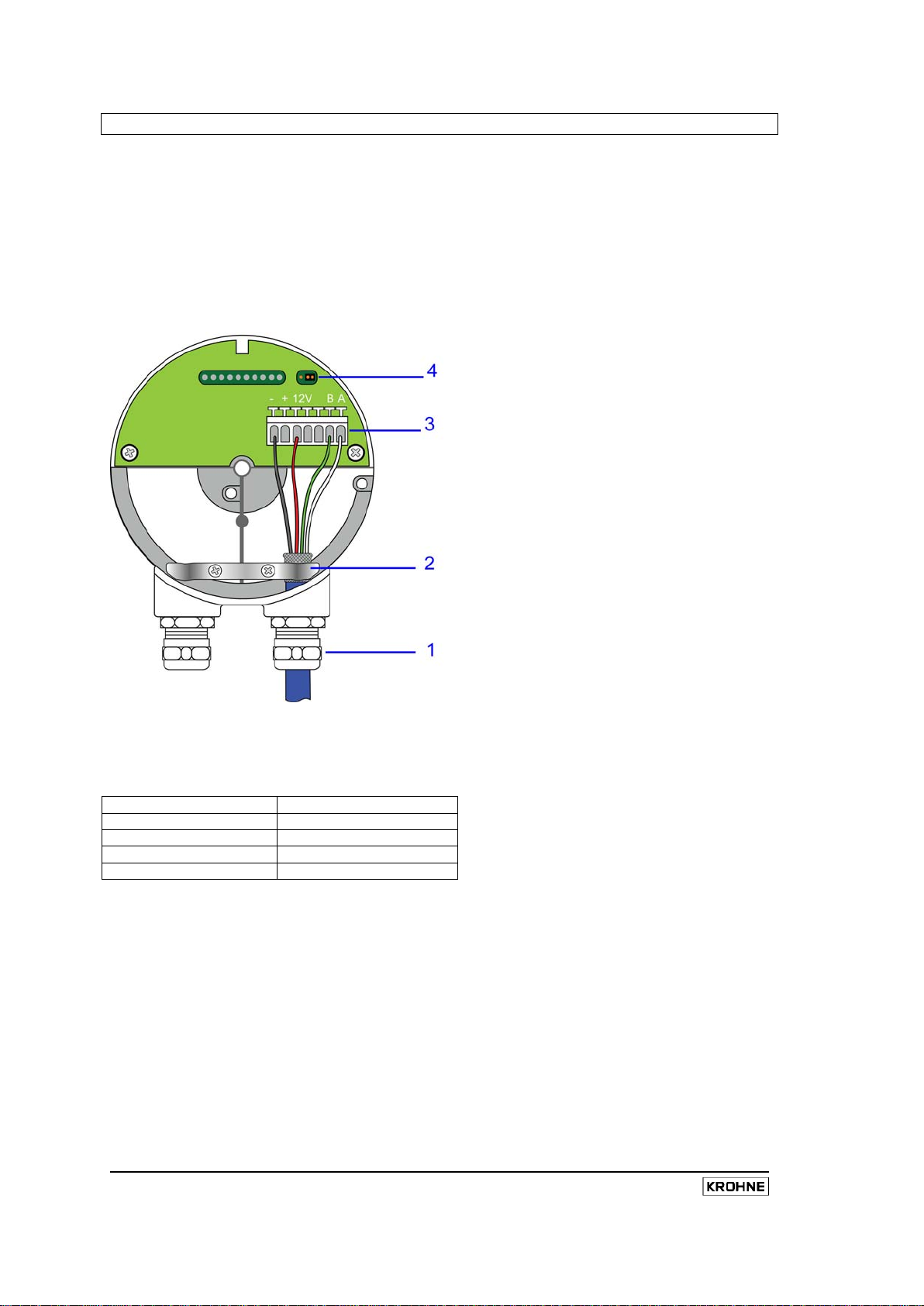
3.3 Connection to the MFC010
1. Unscrew the fixing screw on the junction box cover.
2. Release the two fixing screws holding the cable grip in place and remove the grip.
3. Strip approx. 50mm/2” of the outer casing of the signal cable.
4. Split the screen away from the cores and fold it back on the outer cable.
5. Fit the cable grip and secure, making sure that the screen is gripped under the grip.
6. Connect the four cores to the terminals marked A,B, 12V, - as shown
NOTE: The spring loaded connections are released by depressing the white lever above each
connection
1 Cable Gland
2 Cable Grip/Earth
3 Terminal connections
4 Jumper for EOL resistor (not supplied) – off in position as shown, on in other position
Page 11

9
MFC010 Interface Manual
Page 12
10
MFC010 Interface Manual
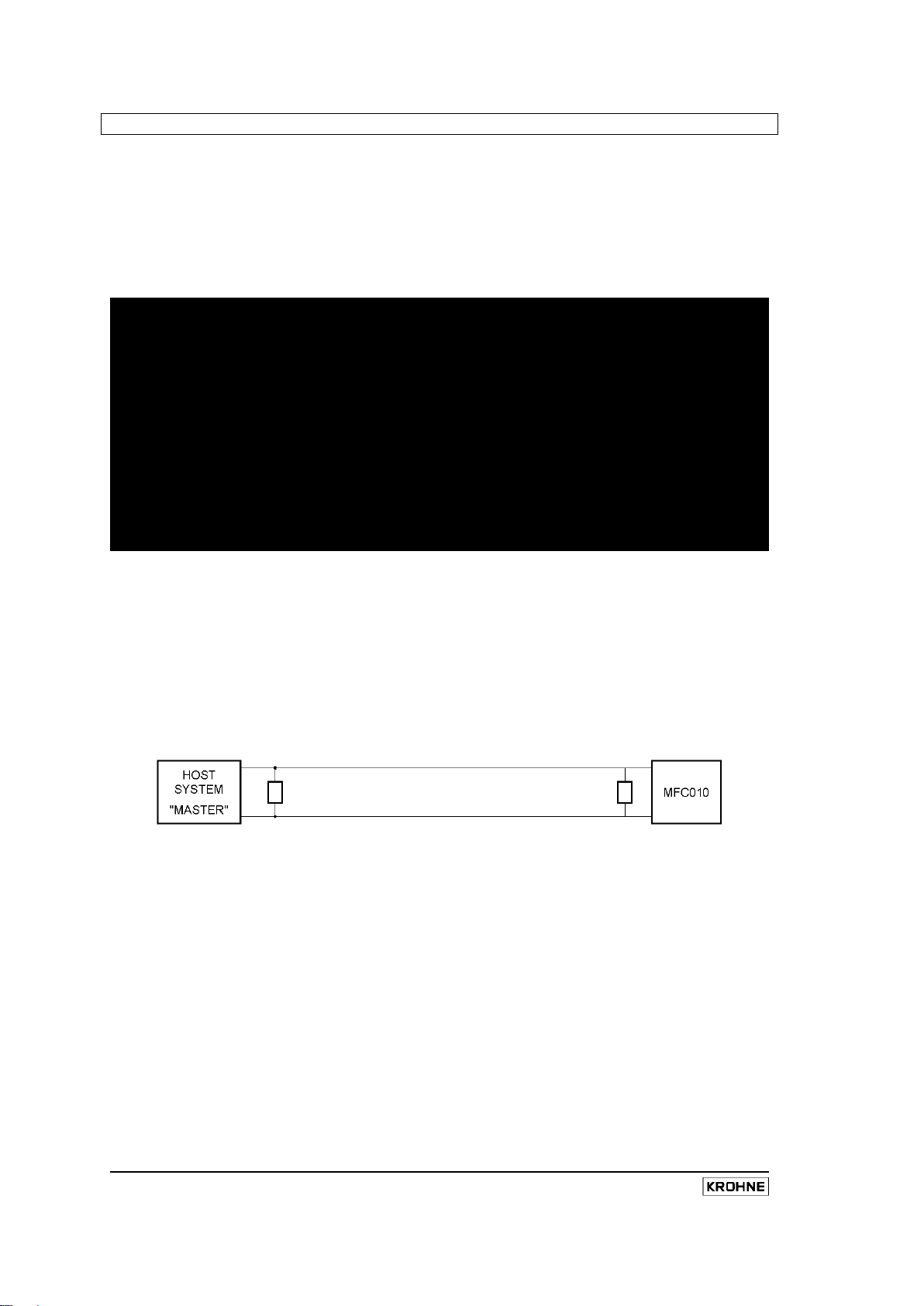
3.4 Connection to the Modbus Bus
The MFC010 is designed to be connected as a Slave device onto the 2-wire bus implementation of the
Modbus physical layer definition. In this configuration the receiver and transmitter lines for each device
are c onnected t ogether, Transmitter A t o R eceiver A and T ransmitter B t o Receiver B, and operated in
Half Duplex mode, where the master transmits a request and only after receiving it does the nominated
slave device transmit a reply. When not responding to a direct request from the Master device, the Slave
devices r emain passive, m onitoring the bus and aw aiting a suitable request from the Master device. In
addition to the A and B signal lines the bus MUST include a “Common” signal line to act as a ground
reference point for the A and B signals.
The m aster bus m ust be t erminated at i ts phy sical end poi nts by suitable termination networks
connected between the A (D0) and B (D1) signal lines. When not using bus-biasing resistors, see next
paragraph, each termination network may consist of a single 150 O hm, 0.5W r esistor. H owever, when
bus-biasing resistors are required, a more suitable termination network would consist of a 1nF capacitor in
series with a 120 Ohm, 0.25W resistor. NB It is common that the Host system “Master” is physically at
one end of the bus, so one of the termination resistors is fitted at its terminals, but it should be r ealised
that this is not always the case and care should be taken to ensure that the termination network is at the
physical end of the bus. In a point-to-point configuration, when only one Slave device is fitted to the bus,
then the terminating networks can simply be situated at the connecting terminals of the master and s lave
devices.
Some slave devices require that Bus-Biasing resistors are fitted to ensure that the bus is in a defined
state w hen none of t he t ransmitting devices are active. The MFC010 does NOT require Bus-Biasing
resistors t o be f itted but is compatible with their presence on t he bus i f one or more of the other slave
devices on the bus require them to be fitted, as long as they comply with the Line Polarization
requirements of the Modbus specification.
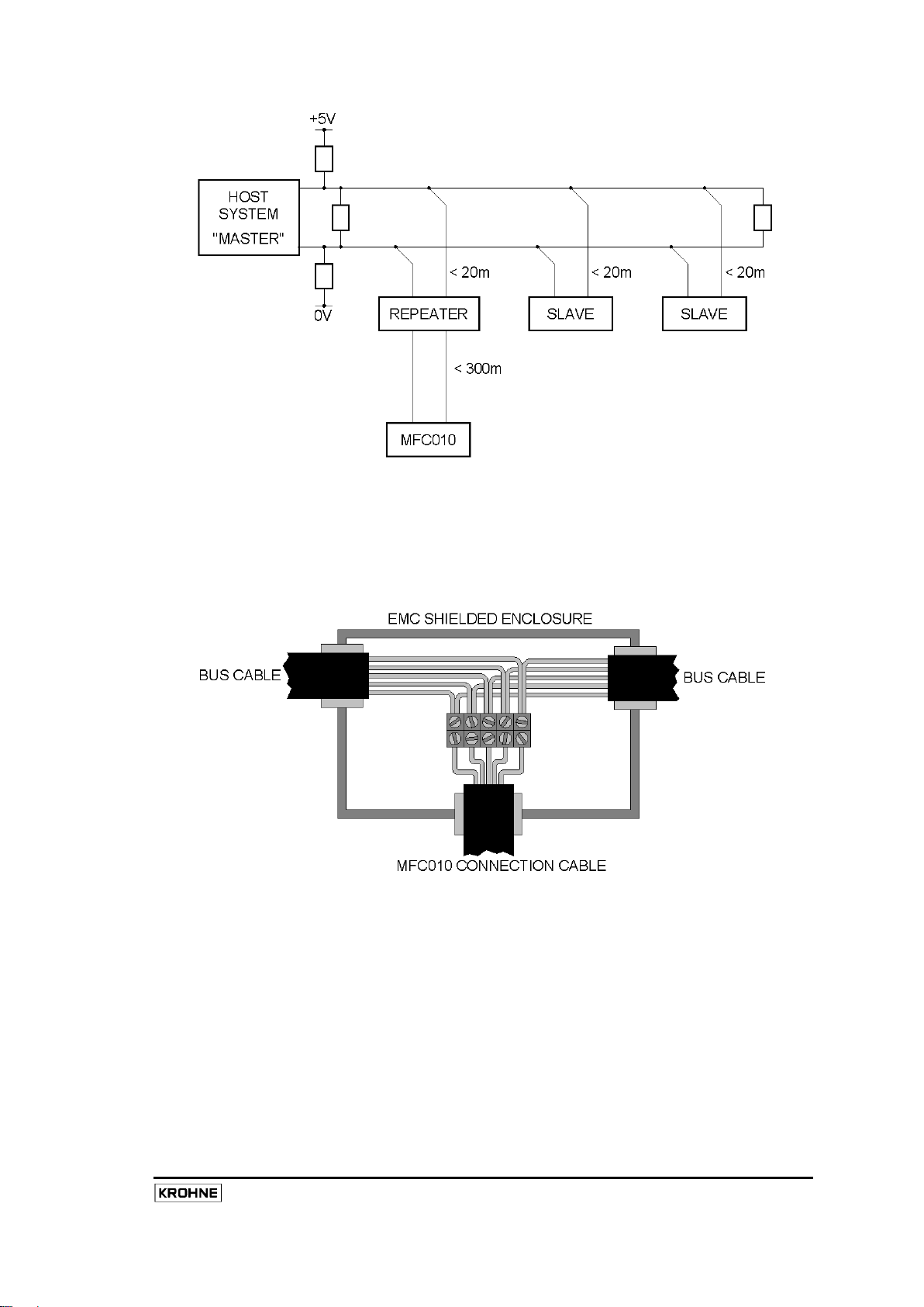
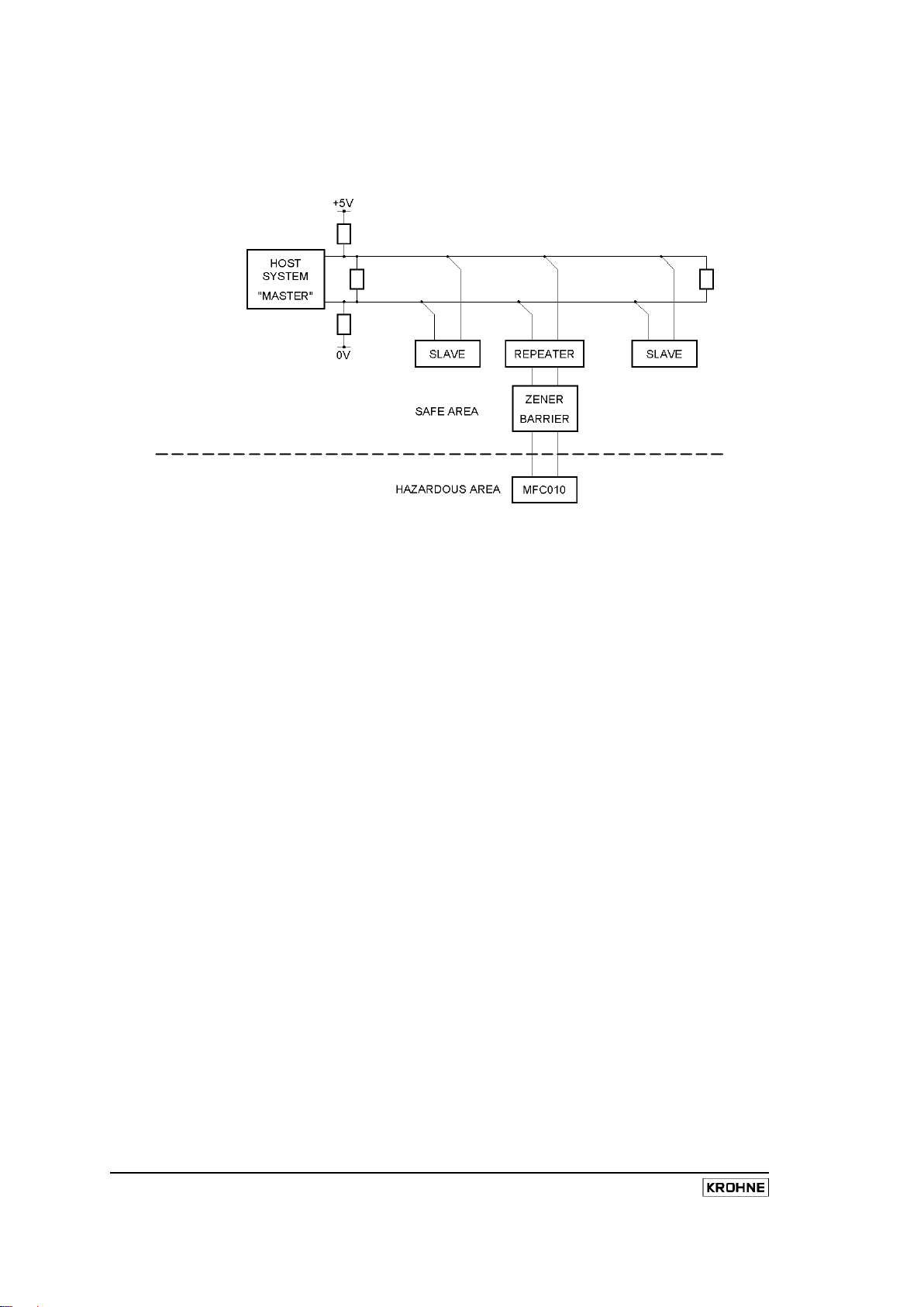
In a m ultidrop bus c onfiguration t he s lave dev ices ar e c onnected t o t he m ain bus cable by branch
connections at intervals along the length of the main bus. T he branch connections, Derivations as they
are termed in the Modbus specification, must be l ess than 20m in length from the main bus cable to the
slave device. Some slave devices permit direct connection to the main bus, known as “Daisy Chaining”,
in some cases by providing extra terminals and c able ac cess poi nts. H owever, as i ndicated i n t he
previous s ections, ac cess t o t he t erminal c ompartment of t he M FC010 i s limited; therefore i t i s not
practical to directly connect the MFC010 to the main bus. Instead, the installation should utilise a short
branch c onnection. I f a greater length of cable is required between the MFC010 device and the main
Modbus bus, the user should install a suitable RS485 repeater between the MFC010 and the bus (refer to
the diagram below).
Page 13
11
Because the connection to the bus requires exposing the signal wires, t he connection to the main bus
should be made within a suitable EMI shielded enclosure. This connection should include the “Common”
signal connection, the power supply connection (if a suitable one is provided by the bus), and the drain
wire when available. Each of the cable screens must be properly terminated to the enclosure by means of
appropriate EMC cable glands. For example:
If t he Bus does not provide a s uitable power s upply for the MFC010, a separate suitable power supply
connection should be made at this point.
An RS485 Repeater can be used to extend the length of the Bus and the number of slave devices that are
attached t o t he bus ( refer t o t he f igure bel ow). H owever, if the bus is extended in such a fashion,
termination and polarization networks should be fitted according to the same rules as used for the main
bus (see descriptions above).
MFC010 Interface Manual
Page 14

12
MFC010 Interface Manual
NB For H azardous A rea appl ications t he us er s hould r efer t o s ection 4.3, on page 17, f or c onnection
details.
NB For multidrop systems, ensure cycle times are properly calculated to ensure bus speeds are adequate
for the application.
3.5 Installation Guidelines for Electromagnetic Compatibility
Whilst t he M FC010 and i ts as sociated s ensor has been des igned, t ested and c ertified t o m eet the
requirements on international s tandards of E lectromagnetic C ompatibility ( EMC), i t i s t he us ers
responsibility to ensure that the connection guidelines described in this document are followed. In addition
the user should use recognised good practise in the location and cable routing of the MFC010 in relation
to its surrounding environment. The us er should consider t he following suggestions w hen installing an
MFC010 into a system.
1. Every effort should be made to avoid significant lengths (>50mm) of unshielded signal wire
when connecting to the system, any terminal connections should be housed in a suitably
shielded enclosure.
2. Avoid routing the cable in groups with or alongside other power carrying cables.
3. Avoid locating the MFC010 or routing the connection cable in close proximity to large
electrically powered equipment, such as pumps, inverters etc.
4. If necessary, route the connection cable through a suitably earthed metal conduit.
Page 15

13
i
i
4. Installation in Hazardous Area Applications
Before installation the user MUST ENSURE that the equipment to be installed is the Hazardous ar ea
approved equipment.
Copies of the appropriate certificates can be found on the KROHNE website at www.krohne.com.
Before installation the user MUST refer to the hazardous area installation document, supplied w ith this
equipment, and strictly adhere to the relevant installation instructions indicated therein.
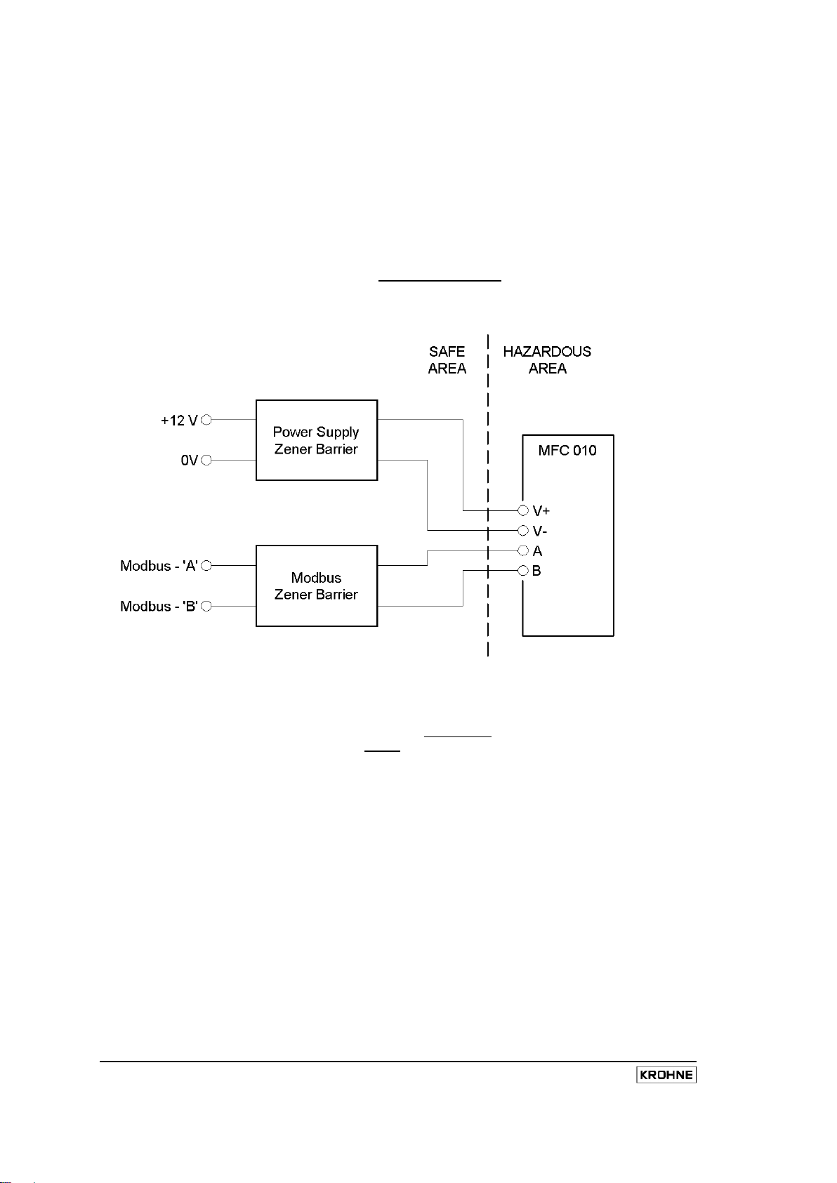
When the MFC010 is used in Hazardous area installations, suitable barrier devices MUST be fitted. The
Safety Parameters for the MFC010 are as follows. All interface and barrier devices must be appropriately
certified to meet these parameters.
ATEX
V+ & V-
Input Voltage, U
Input Current, I
Input Power, P
Input Capacitance, C
Input Inductance, L
i
i
i
i
i
16.5V
340mA
1.3W
35nF
10µH
A & B
FM
V+ & V-
Input Voltage, U
Input Current, I
Input Power, P
Input Capacitance, C
Input Inductance, L
i
i
i
Input Voltage, U
Input Current, I
Input Power, P
Input Capacitance, C
Input Inductance, L
i
i
i
i
i
11.8V
40mA
120mW
35nF
10µH
16.2V
317mA
1.28W
35nF
10µH
A & B
Input Voltage, U
Input Current, I
Input Power, P
i
i
i
Input Capacitance, C
Input Inductance, L
i
i
11.8V
34mA
90mW
35nF
10µH
MFC010 Interface Manual
Page 16
14
MFC010 Interface Manual
The output safety par ameters of t he bar rier dev ices m ust not ex ceed t he V oltage, P ower and C urrent
limits set out above. T he output Capacitance parameter for the barrier devices must exceed the sum of
the M FC010 i nput C apacitance, s pecified abov e, and t he m aximum c able Capacitance. The output
Inductance par ameter f or t he bar rier dev ices m ust ex ceed t he sum of the MFC010 input Inductance,
specified above, and maximum cable Inductance. To summarise:
Uo Barrier < U
Barrier < I
I
o
Barrier < P
P
o
Barrier > C
C
o
Barrier > L
L
o
MFC010
i
MFC010
i
MFC010
i
+ C
cable
cable
MFC010
i
+ L
MFC010
i
NB The In-line resistance of the Modbus barrier MUST NOT EXCEED 1000 Ohms for each of the A and
B Input terminals.
The Z ener barrier devices must be i nstalled in an E MI s hielded enc losure and t he cable screen(s) kept
intact right up to the barrier terminals as far as is practical. The cable screen(s) should be terminated to
the enclosure, chassis Earth connection, and kept SEPARATE from t he i ntrinsically s afe E arth
connections of the Barrier devices. The user MUST adhere to the barrier manufacturer’s instructions for
connecting the intrinsically safe Earth connection to the barrier devices.
Page 17
15
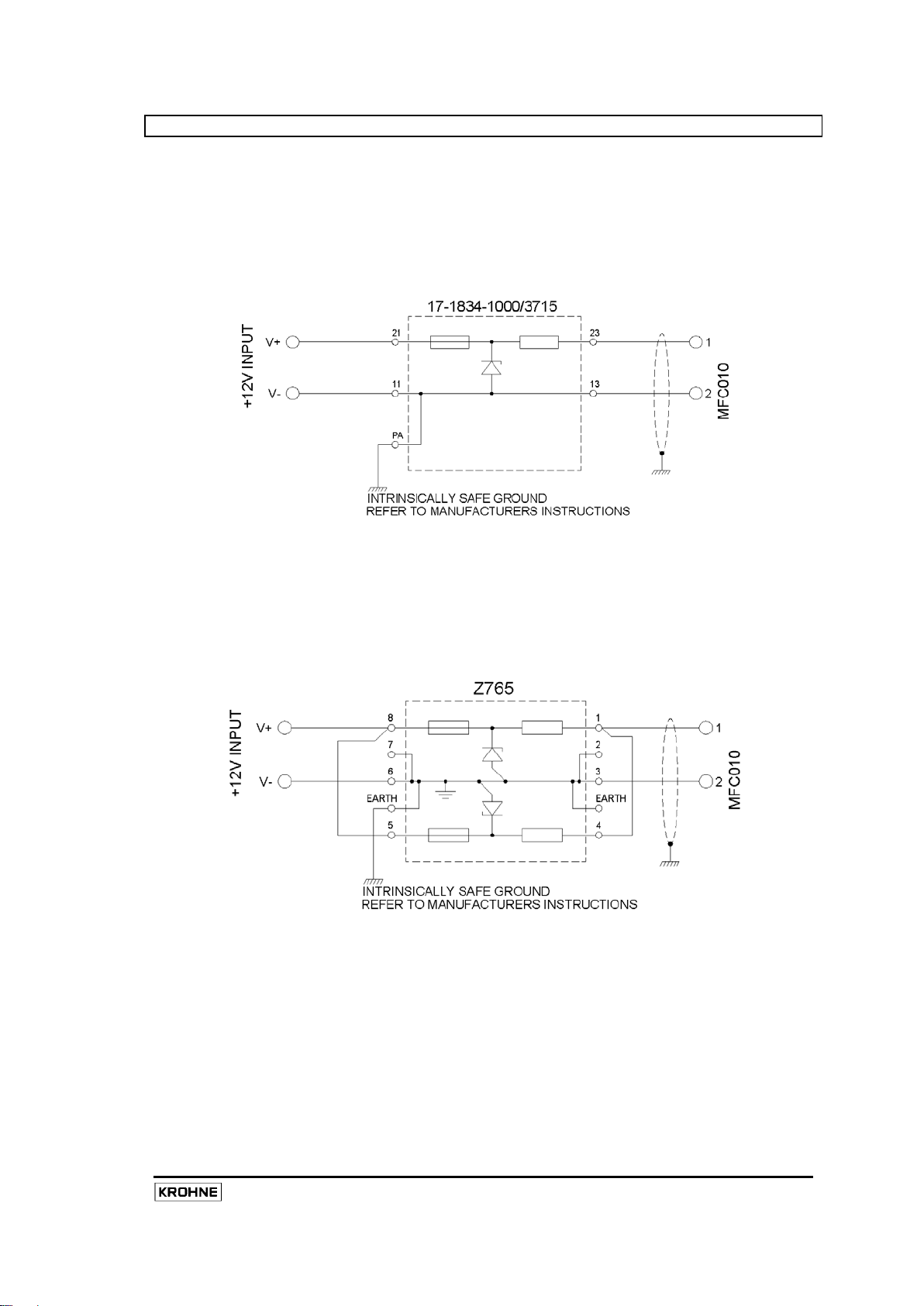
4.1 Power Supply Barrier Devices
The following Zener Barrier devices are those that are recommended for use on the V+ & V- power supply
input connections to the MFC010.
Manufacturer : Bartec
Part Number : 17-1834-1000/3715
Ex Approvals : EEx ia/ib IIC
Connection :
Manufacturer : Pepperl & Fuchs
Part Number : Z765
Ex Approvals : EEx ia IIC
FM and CSA Approved
Connection :
Note: For Optimass 2000 the supply voltage to the barrier should be +14V to ensure maximum voltage is
supplied to the meter.
MFC010 Interface Manual
Page 18
16
MFC010 Interface Manual
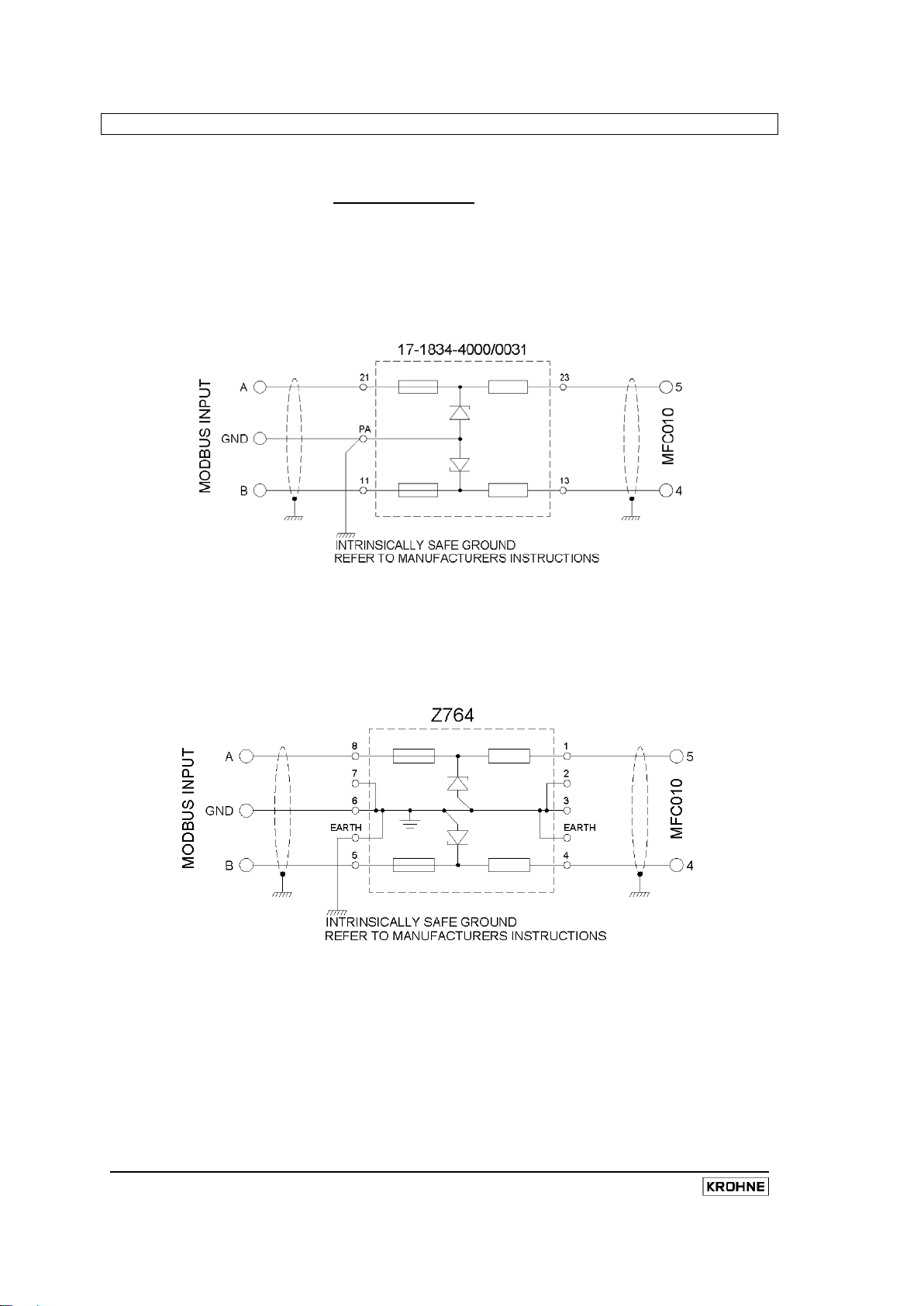
4.2 Modbus Barrier Devices
The following Zener Barrier devices are those that are recommended for use on the A & B Modbus input
connections to t he M FC010. W hen s pecifying al ternate dev ices t he us er m ust ens ure t hat t he i n-line
resistance of t he M odbus bar rier DOES NOT EXCEED 1000 O hms f or eac h of t he A and B I nput
terminals.
Manufacturer : Bartec
Part Number : 17-1834-4000/0031
Ex Approvals : EEx ia/ib IIC
Connection :
Manufacturer : Pepperl & Fuchs
Part Number : Z764
Ex Approvals : EEx ia IIC
FM and CSA Approved
Connection :
Page 19
17
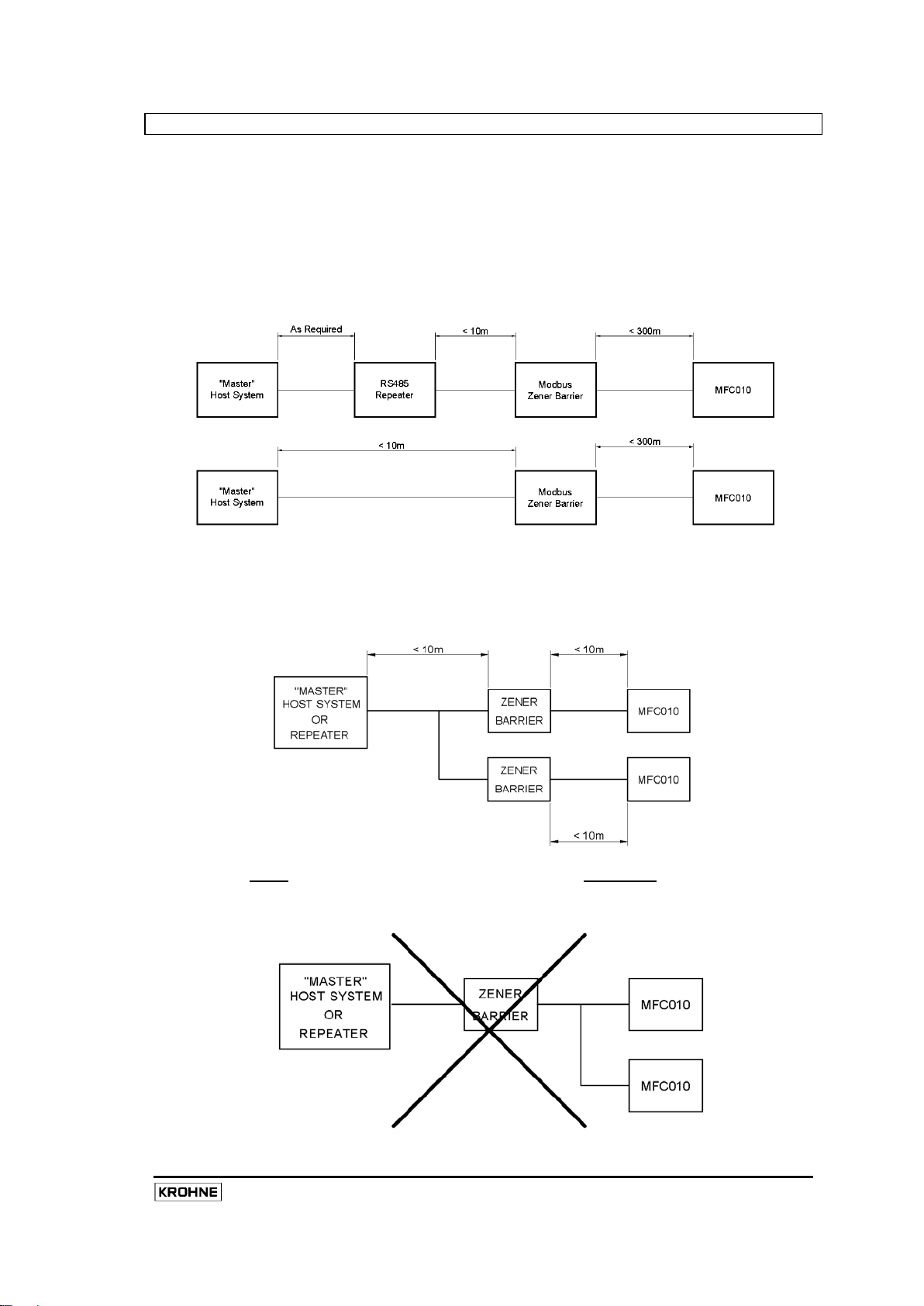
4.3 Connection To The Modbus Bus
When installed in hazardous area application the MFC010 i nterface i s not di rectly c ompatible w ith t he
Modbus interface standard due to the presence of the required Zener Barrier devices.
In a poi nt-to-point configuration, when the MFC010 is the only device on the bus, the cable length from
the barriers to the “Master” host system must not exceed 10m in length. If a greater distance is required,
the us e of a s uitable R S485 repeater is recommended, in which case the repeater connection to the
Zener B arrier dev ices s hould not ex ceed 10m i n l ength. T he m aximum c able l ength bet ween t he
Repeater and the “Master” host system is determined by the operating limits of those two devices. T he
cable length from the Modbus barrier device to the MFC010 must be less than 300m i.e.
Where the distance from the barrier device to the MFC010 is less than 10m, two barrier devices may be
connected in parallel to the “Master” host system, or the repeater if one is being used, refer to the diagram
below. The overall cable length from the Host/repeater to the barrier devices must still be less than 10m
as described previously. If more than two devices are required to be connected then a dedicated repeater
should be used for each.
Each MFC010 MUST have its own dedicated barrier interface; they MUST NOT be connected in parallel
on the hazardous area side of the system.
MFC010 Interface Manual
Page 20
18
MFC010 Interface Manual
In a multidrop installation, see figure below, the Zener Barrier devices must be connected to the bus using
a s uitable R S485 repeater, with the c onnecting c able bet ween the Barrier devices and t he repeater not
exceeding 10m. The connection of the repeater to the Modbus bus must then follow the rules and
restrictions of the Modbus protocol as indicated previously in section 3.4.
Page 21
19
5. Modbus Protocol Interface
The interface to the MFC010 is implemented in the Modbus RTU communications pr otocol, and i s done
so in accordance with the specification and requirements of the “Modbus Protocol Reference Guide” (PIMBUS-300 R ev J ). The phy sical el ectrical par ameters of t he M odbus s pecification are def ined by the
EIA/TIA-485 (RS485) standard and t he “ Modbus ov er S erial Li ne - Specification and I mplementation
Guide V1.0” interface definition.
In a serial communications system such as the Modbus protocol, data is transmitted as a series of voltage
levels along the connecting data wires. A “bit”, or binary digit, value is determined by the logical level
(high or low) of the connecting interface over a set time period. The time period for each bit is determined
by the transmission speed, known as the baud rate. For a baud r ate of 9600, the bit period is 1/9600 =
104.2 m icroseconds. T he MFC010 supports Baud r ates of 1200, 2400, 4800, 9600, 19200, 38400 and
57600 baud (see the Baud rate setting in Holding Register No. 1005). The higher transmission speeds
require careful attention to the cable installation in order to function reliably and error free (see Section 3.2
on page 7 for installation details).
5.1 Character Transmission Format
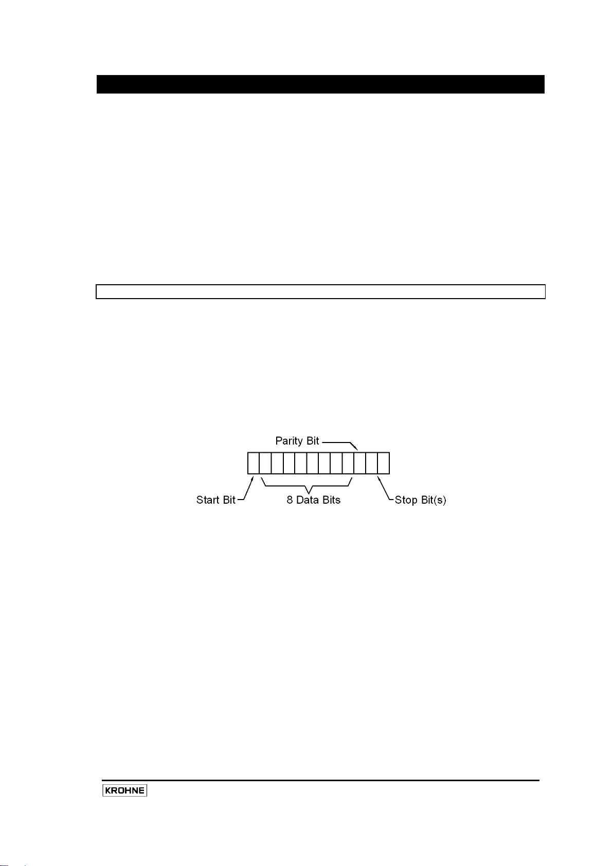
Data is transmitted in sets of 8 bit data blocks, known as “Bytes” or “Characters”. Each character i s
preceded and followed by framing bits that permit the correct detection of the transmitted character. The
first “Bit” transmitted will be the “Start” bit, this permits the receiving device to detect that a character is
being transmitted. The “Start” bit is then followed by the 8-bit data byte. A “Parity” bit may then follow the
8-bit character. T his “Parity” bit is optional (see the Transmission format setting in Holding Register No.
1004), it allows the system to validate the c ontents of the 8-bit data byte to ensure that no er rors have
occurred during transmission. Following the “Parity” bit is the “Stop” bit that indicates the end of the
transmitted character to the receiving device. If no parity bit is used, two stop bits must be implemented,
this ensures a consistent character length of 11 bits is maintained.
The 8 dat a bits are annotated from bit 0 ( the least significant bit, LSB) to bi t 7 ( the most significant bit,
MSB). The character is transmitted “MSB first”, i.e. the first bit after the start bit, is bit 7 of the data byte.
See appendix B for more details on binary coding.
MFC010 Interface Manual
Page 22

20
MFC010 Interface Manual
5.2 Modbus Telegram Format
The messages between the Modbus master and slave devices are transmitted as groups of characters,
as des cribed abov e, c ollectively k nown as t elegrams. E ach t elegram i s preceded and followed by a
“Quiet” period on t he Modbus bus of 3½ character periods. T he “Quiet” period following the telegram is
used to indicate the end of the telegram.
The first character received in the telegram identifies the slave device to which or from which the telegram
is bei ng t ransmitted. T his f irst c haracter i s k nown as t he S lave I D or S lave A ddress. In multidrop
configurations (see Section 5.4 below) this address character is used by the master device to individually
communicate with one of the instruments on the bus connection. T he Slave device returns this value to
indicate to the master the source of the response telegram. The Slave Address value for the MFC010 can
be set using Holding register No. 1006 (see Section 7.5).
The s econd character received in the telegram is the function command code r equested by the master
device. A list of the function codes supported by the MFC010 can be f ound in Section 6 (See Page 23)
along with a description of each.
The last two characters received form a 16 -bit checksum value. T his checksum value is used to ensure
that t he dat a r eceived i n t he t elegram has not been c orrupted. T he c hecksum i s calculated and
appended to the telegram by the transmitting device (Slave or Master) and the receiving device compares
the received checksum value against the value it calculates from the received data. If the data has been
corrupted in some way during transmission, then the checksum calculated by the receiving device will be
different than that which it received with the telegram. The receiving device will then ignore the telegram
knowing t hat t he dat a w ithin i s unr eliable. S ee A ppendix A for information on the Modbus Checksum
calculation.
Between t he function code character and t he CRC checksum at the end of the telegram is the telegram
data. The contents and format of these data characters is dependant upon the function code requested.
5.3 Data Types in Modbus
There are two data types used to transmit information on a Modbus data bus, the “Bit” and the “Register”.
The “Bit” represents a s ingle binary state, whether as an output or an input condition. The “Register” is a
16-bit integer transmitted as two 8-bit c haracters. U sing multiple “ Registers” the Modbus interface c an
transmit higher accuracy values such as “Floating Point” and “Double Precision Floating Point” numbers.
“Bit” variables are packed into 8 bit bytes, so each character sent or received can contain up t o 8 “ Bit”
variables. The Master and Slave devices use only as many 8 bit data characters as are required to
transmit the information. Any unused bits in the data characters are ignored. The bit that is first indexed
by the Master request address is transmitted in the LSB, Bit 0, of the first data character. T he next “Bit”
value i s t ransmitted i n t he nex t bi t, B it 1, of t he f irst dat a c haracter. T his c ontinues until the last bit
location, Bit 7, of the first data character is used. The next “Bit” value is then transmitted in the LSB, Bit 0,
of the following data character, this continues until all of the requested values have been transmitted. Any
unused bit locations in the last data character are filled out with “0”s
For simple single register variables the Most Significant Character of the register is transmitted first, with
the Least Significant character following i mmediately after. H owever, f or variables that r equire m ultiple
registers, i.e. the “Floating Point” and “Double Precision Floating Point” variables, the transmission order
is a little more complicated. i.e.
Page 23

21
Single 16 Bit Register Variables, Data Transmission Order
Byte 1, MS Byte Byte 0, LS Byte
Long Integer & Floating Point Variables, Data Transmission Order
Byte 1 Byte 0, LS Byte Byte 3, MS Byte Byte 2
Requested Register Requested Register + 1
Double Precision Floating Point Variables, Data Transmission Order
1 0 3 2 5 4 7 6
Requested Register Register + 1 Register + 2 Register + 3
5.4 Multidrop Operation
A “Master” dev ice, s uch as a P C or P LC, c an be us ed t o control and i nterrogate a num ber of “ Slave”
devices, such as an MFC010, connected to the Modbus bus in a “Multidrop” configuration. The “Master”
device always initiates the communication interchange with the “Slave” devices, each of which waits for
instructions or requests from the “Master” before transmitting dat a on t he bus i n r esponse t o t he
instruction. Although the Modbus specification allows for up to 247 “Slave” devices to be physically
connected to the bus at any time, the Master device can only request information from one “Slave” device
at a time. A unique ID number or “Address” is allocated to each of the “Slave” devices to allow the
“Master” to differentiate between them. Although it does not matter in which order the “Slave” devices are
interrogated, the “Master” must wait for the response, or for a suitable period after the request, before
making a request to any other of the slave devices on the bus.
Under some limited conditions, i.e. when the instruction to the “Slave” device does not require a detailed
response, the “Master” device can send a “Broadcast” command, indicated by a “Slave” ID Address of “0”,
to all of the slave devices simultaneously.
5.5 Calculating Data Transmission Rates
Careful attention should be made to ensuring that the bus installation can support the amount and rate of
data t ransmission r equired. C onsideration of t he l imitations of the physical installation, as previously
described, s hould not be i gnored. T he m aximum us able t ransmission s peed, baud r ate, w ill depend
entirely upon the installation.
The transmission format also needs to be carefully considered. In the Modbus standard, each transmitted
character is 11 bi ts long, depending upon t he setting of the transmission f ormat. A t the Modbus default
transmission speed of 19200 baud, each character will have a transmission period of 573 microseconds.
For a simple data transfer of one Input value (see section 6.4 on page 26 for details) between the master
and slave will require an 8 character (+ 2 x 3½ character “Quiet” periods) telegram in the request from the
master, and a 9 character (+ 2 x 3½ character “Quiet” periods) telegram in the response from the slave. If
the Slave responds immediately the cycle from the Master sending the request to receiving the response
will be at least 31 characters long, or 17.8 milliseconds at 19200 baud. T herefore the maximum rate of
data requests that could be made is 56 every second.
In m ost c ases f ar m ore dat a w ill be required, and i n m ultidrop s ystems t he m aster dev ice m ay be
requesting data from up to 64 units. In these circumstances the user must ensure that there is sufficient
time i nterval bet ween r equests f or t he m easured v alues t o be received without overlapping the Master
request telegram with the previous slave reply telegram.
To achieve the required update rates the user may have to consider whether, in a multidrop configuration,
the number of devices on a bus must be l imited or whether the cable installation will support one of the
higher data transmission speeds which are available.
This is especially important where fast response is required (such as batch filling operations).
MFC010 Interface Manual
Page 24

22
MFC010 Interface Manual
5.6 Error Messages in Modbus
When t he M FC010 det ects an error i n t he r equest r eceived i n a pr operly f ormatted t elegram, i t w ill
respond with an error message. The error message response telegram is formatted as follows.
Address Function Error Code CRC CRC
The most significant bit of the requested function code is set (add 128, 80
) in the response telegram to
16
indicate that an error has been detected. For example, if an error were detected in a Function 1 request,
then the returned function code would be 81
(129).
16
The single data character in the response telegram will indicate the type of error detected. These are as
follows.
1 Illegal Function The requested function code is not supported by
the MFC010 or is not valid due to the current
settings of the device.
2 Illegal Data Address The Register requested is not valid.
3 Illegal Data Value The requested data (in Write operations only) is
invalid for the register being written.
6 Slave Device Busy The MFC010 is unable to process the requested
command because an EEPROM save is in progress.
Errors due t o c ommunications f aults ( CRC er rors, P arity er rors et c) ar e logged but no response is
returned because the data in the received telegram is deemed unreliable. T he Master system can read
the error logs by using the diagnostic command (Function 08, see Section 6.8).
Page 25

23
6. Modbus Functions Supported by the MFC010
6.1 01 (0116): Read Coil Status
This f unction permits the user to read the state of a number of consecutive Discrete Outputs, or “Coil”,
registers. Within the MFC010 the majority of the Discrete Outputs are used to initiate command functions;
when read, response will be “ 1” w hilst c ommand i s bei ng processed and “ 0 when t he c ommand i s
completed (See Section 7.2 on page 39 for details of the individual Status Output registers). The format
of the Master request telegram for this function should be as follows.
Request
Character
1 Slave Address 0116 Request to Slave ID 1
2 Function 0116 “Read Coil Status”
3 Start Address Hi 0316
4 Start Address Lo E916
5 No of Points Hi 0016
6 No of Point Lo 0516
7 CRC Lo 2D16
8 CRC Hi B916
The MFC010 will respond to such a request with a telegram formatted as follows.
Response
Character
Field For Example
Start Address = 1002
No. of Points = 5
( “Coils” 1002 – 1006 )
CRC Checksum
Field For Example
1 Slave Address 0116 Response from Slave ID 1
2 Function 0116 “Read Coil Status”
3 Data Bytes in Response 0116 1 byte (5 States requested < 8 Bits)
4 Data Byte 1 1516 Data = 000101012
5 CRC Lo 9016
6 CRC Hi 4716
The number of data bytes in the response will depend upon the number of Discrete Outputs requested.
The appropriate bit in each of the data bytes received will indicate each Discrete Output state requested.
Therefore, each data byte in the response will contain a maximum of 8 Discrete Output “Coil” states. For
example, if 19 Discrete Outputs are requested, then three data characters will be r eturned, with the first
group of 8 out put states encoded in the first data byte, the second group of 8 out put states coded in the
second data byte, and the last 3 output s tates coded in the first three bit locations of the last data byte.
Bit 0 of the first response data byte will c orrespond t o t he “ Start A ddress” D iscrete O utput r egister
specified by the request telegram. B it 0 of the second response data byte will correspond to the “Start
Address” + 8 Discrete Output register and so on.
In the example above, 5 Discrete Outputs are r equested, s o onl y one dat a by te i s r equired i n t he
response. The response data value shown above i ndicates t hat r egisters 1002, 1004 and 1006 ar e
active, and that registers 1003 and 1005 are inactive.
CRC Checksum
MFC010 Interface Manual
Page 26

24
MFC010 Interface Manual
6.2 02 (0216): Read Discrete Input
This function permits the user to read the state of a number of consecutive Discrete Input registers. (See
Section 7.3, on page 41, for details of the individual registers). The format of the Master request telegram
for this function should be as follows.
Request
Character
1 Slave Address 0116 Request to Slave ID 1
2 Function 0216 “Read Discrete Input”
3 Start Address Hi 0316
4 Start Address Lo E816
5 No of Points Hi 0016
6 No of Point Lo 0C16
7 CRC Lo F816
8 CRC Hi 7F16
The MFC010 will respond to such a request with a telegram formatted as follows.
Response
Character
Field For Example
Start Address = 1001
No. of Points = 12
( “Inputs” 1001 – 1011 )
CRC Checksum
Field For Example
1 Slave Address 0116 Response from Slave ID 1
2 Function 0216 “Read Discrete Input”
3 Data Bytes in Response 0216 2 bytes
4 Data Byte 1 CD16 Data = 110011012
5 Data Byte 2 0916 Data = 000010012
6 CRC Lo 2D16
7 CRC Hi 2E16
The num ber of dat a by tes i n t he r esponse will depend upon the number of Discrete Inputs requested.
The appropriate bit in each of the data bytes received will indicate each Discrete Input state requested.
Therefore, each data by te i n t he r esponse w ill c ontain a m aximum of 8 di screte i nput s tates. F or
example, if 19 Discrete Inputs are requested, then three data characters will be returned, with the first
group of 8 input states encoded in the first data byte, t he s econd gr oup of 8 i nput states c oded i n t he
second data byte, and the last 3 input states coded in the first three bit locations of the last data byte. Bit
0 of the first response data byte will correspond to the “Start Address” Discrete Input register specified by
the request telegram. B it 0 of the second response data byte will correspond to the “Start Address” + 8
Discrete Input register and so on.
In the example above, 12 Discrete Inputs are requested, so two data bytes are required in the response.
CRC Checksum
Page 27

25
6.3 03 (0316): Read Holding Registers
This f unction per mits t he us er t o r ead t he v alue of a number of consecutive Holding registers. (See
Section 7.5 on page 49 for details of the individual registers). The format of the Master request telegram
for this function should be as follows.
Request
Character
1 Slave Address 0116 Request to Slave ID 1
2 Function 0316 “Read Holding Registers”
3 Start Address Hi 0316
4 Start Address Lo FE16
5 No of Points Hi 0016
6 No of Point Lo 0316
7 CRC Lo 6416
8 CRC Hi 7F16
The MFC010 will respond to such a request with a telegram formatted as follows.
Response
Character
Field For Example
Start Address = 1023
No. of Points = 3
( Input Registers 1023 – 1025 )
CRC Checksum
Field For Example
1 Slave Address 0116 Response from Slave ID 1
2 Function 0316 “Read Holding Registers”
3 Data Bytes in Response 0616 6 bytes ( 3 x 2 Byte Registers )
4 Data Byte 1 3F16
5 Data Byte 2 4916
6 Data Byte 3 0216
7 Data Byte 4 D416
8 Data Byte 5 F116
9 Data Byte 6 2216
10 CRC Lo 7D16
11 CRC Hi BD16
Register 1023 = 16201
Register 1024 = 724
Register 1025 = 61730
CRC Checksum
MFC010 Interface Manual
Page 28

26
MFC010 Interface Manual
6.4 04 (0416): Read Input Registers
This function permits the user to read the value of a number of consecutive Input registers. (See Section
7.5 on page 493 for details of the individual registers). The format of the Master request telegram for this
function should be as follows.
Request
Character
1 Slave Address 0116 Request to Slave ID 1
2 Function 0416 “Read Input Registers”
3 Start Address Hi 0B16
4 Start Address Lo B816
5 No of Points Hi 0016
6 No of Point Lo 0216
7 CRC Lo F316
8 CRC Hi CA16
The MFC010 will respond to such a request with a telegram formatted as follows.
Response
Character
Field For Example
Start Address = 3001
No. of Points = 2
( Input Registers 3001 – 3002 )
CRC Checksum
Field For Example
1 Slave Address 0116 Response from Slave ID 1
2 Function 0416 “Read Input Registers”
3 Data Bytes in Response 0416 4 bytes ( 2 x 2 Byte Registers )
4 Data Byte 1 9416
5 Data Byte 2 7B16
6 Data Byte 3 4216
7 Data Byte 4 9616
8 CRC Lo 1716
9 CRC Hi 6316
In t he ex ample abov e t he I nput r egister r equested c ontains a f loating poi nt num ber and needs to be
accessed as a pai r of r egisters ( 3001/3002). T he r esulting 4 by tes i n t he dat a r esponse c an t hen be
decoded into a floating-point number (See Section 5.3 on page 20 and Appendix C on page 93 for further
details on encoding and decoding floating point numbers).
Register 3001 / 3002 = 75.29
CRC Checksum
Page 29

27
6.5 05 (0516): Force Single Coil
This function permits the user to set the state of a single Discrete Output “Coil” register. (See Section 7.2
on page 39 for det ails of t he i ndividual r egisters). I n t he M FC010 implementation, these registers are
used t o i nitiate c ommands and functions. S etting t he O utput s tate i nitiates t he f unction, at tempting t o
clear t he O utput s tate w ill r esult i n a dat a er ror. The format of the Master request telegram for this
function should be as follows.
Request
Character
1 Slave Address 0116 Request to Slave ID 1
2 Function 0516 “Force Single Coil”
3 Coil Address Hi 0316
4 Coil Address Lo E816
5 Force Data Hi FF16
6 Force Data Lo 0016
7 CRC Lo 0C16
8 CRC Hi 4A16
The MFC010 will respond to such a request with a telegram formatted as follows.
Response
Character
Field For Example
Coil Address = 1001
Set Coil “Active”
CRC Checksum
Field For Example
1 Slave Address 0116 Response from Slave ID 1
2 Function 0516 “Force Single Coil”
3 Coil Address Hi 0316
4 Coil Address Lo E816
5 Force Data Hi FF16
6 Force Data Lo 0016
7 CRC Lo 0C16
8 CRC Hi 4A16
The MFC010 (slave) response telegram should be an exact duplicate of the master request telegram.
Coil Address = 1001
Set Coil “Active”
CRC Checksum
MFC010 Interface Manual
Page 30

28
MFC010 Interface Manual
6.6 06 (0616): Preset Single Register
This function permits the user to set the value of a single Holding register. For this reason this command
cannot be used to write to variables that occupy multiple consecutive registers such as floating point and
long integer v ariables (See Section 7.5 on page 49 for details of the individual registers). The format of
the Master request telegram for this function should be as follows.
Request
Character
1 Slave Address 0116 Request to Slave ID 1
2 Function 0616 “Preset Single Register”
3 Register Address Hi 0316
4 Register Address Lo FB16
5 Preset Data Hi 0016
6 Preset Data Lo 2316
7 CRC Lo B916
8 CRC Hi A616
The MFC010 will respond to such a request with a telegram formatted as follows.
Response
Character
Field For Example
Register Address = 1020
Set Register 1020 = 35
CRC Checksum
Field For Example
1 Slave Address 0116 Response from Slave ID 1
2 Function 0616 “Preset Single Register”
3 Register Address Hi 0316
4 Register Address Lo FB16
5 Preset Data Hi 0016
6 Preset Data Lo 2316
7 CRC Lo B916
8 CRC Hi A616
The MFC010 (slave) response telegram should be an ex act dupl icate of t he m aster r equest
Register Address = 1020
Set Register 1020 = 35
CRC Checksum
Page 31

29
6.7 07 (0716): Read Exception Status
When the Master device requests this command function, the MFC010 will respond with a single 8 bit
data character summarizing the status of the instrument. The Master query telegram format is.
Request
Character
Field For Example
1 Slave Address 0116 Request to Slave ID 1
2 Function 0716 “Read Exception Status”
3 CRC Lo 4116
4 CRC Hi E216
CRC Checksum
The MFC010 will respond to such a request with a telegram formatted as follows.
Response
Character
Field For Example
1 Slave Address 0116 Response from Slave ID 1
2 Function 0716 “Read Exception Status”
3 Status 3D16 Data = 001111012
4 CRC Lo E316
5 CRC Hi E116
CRC Checksum
The Status character received in the response will be formatted as follows :
Bit 0
(LSB)
Bit 1
System State : 00
01
10
11
= Measuring,
2
= Standby,
2
= Stop,
2
= Start-up.
2
Bit 2 EEPROM Save Status : 0 = All Data Saved to EEPROM
1= Data Write to EEPOM Pending
Bit 3 Process Control Status :
0 = Process Control Inactive (Control Condition Invalid)
1 = Process Control Active (Control Condition Valid)
Bit 4 Zero Calibration Status : 0 = Zero Calibration OK
1 = Zero Calibration Error
Bit 5 Density Calibration Status : 0 = Density Calibration OK
1 = Density Calibration Error
Bit 6 Process Warning Status : 0 = No Process Warning Flag(s) Detected
1 = Process Warning Flag(s) Detected
Bit 7 (MSB) System Error Status : 0 = No System Error Flag(s) Detected
1 = System Error Condition Flag(s) Detected
MFC010 Interface Manual
Page 32

30
MFC010 Interface Manual
6.8 08 (0816): Diagnostics
This command function permits the user to per form one of s everal di agnostic oper ations, s uch as
retrieving t he er ror and ev ent l ogs. F or f urther det ails on t his c ommand function, refer to the Modbus
specification.
6.9 11 (0B16): Fetch Comm. Event Counter
This f unction allows the master device to det ermine i f r equest telegrams are being properly processed.
The Event count returned is a count of the number of request telegrams which have been received and
processed without errors occurring. By fetching the Event count before and after a series of messages the
master can determine whether the messages were handled normally. When the Master device requests
this command function the MFC010 will respond with a two character (16 bit) status value and a two
character event count. The Master request telegram should be formatted as follows.
Request
Character
Field For Example
1 Slave Address 0116 Request to Slave ID 1
2 Function 0B16 “Fetch Comm. Event Counter”
3 CRC Lo 4116
4 CRC Hi E716
CRC Checksum
The MFC010 will respond to such a request with a telegram formatted as follows.
Response
Character
Field For Example
1 Slave Address 0116 Response from Slave ID 1
2 Function 0B16 “Fetch Comm. Event Counter”
3 Status Hi FF16
4 Status Lo FF16
5 Count Hi 1E16
6 Count Lo D316
7 CRC Lo EC16
8 CRC Hi 1216
Instrument Status
Event Count = 7891
CRC Checksum
The s tatus value is either FFFF
, i n w hich case the slave is still processing a c ommand, or 000016, i n
16
which case the slave is ready to receive the next command request.
Page 33

31
6.10 16 (1016): Preset Multiple Registers
This function permits the user to set the v alue of a num ber of c onsecutive H olding r egisters. T his
command function must be used to write to variables which occupy multiple consecutive registers such as
floating point and long integer variables (See Section 7.5 on page 49 for details of the individual
registers). Some of the Variables which occupy single (16 bit) registers c annot be s et us ing t his
command, the Password registers (1001-1003) in particular. Command Function 06 (06
) must be used
16
to set these registers. The format of the Master request telegram for this function should be as follows.
Request
Character
Field For Example
1 Slave Address 0116 Request to Slave ID 1
2 Function 1016 “Preset Multiple Registers”
3 Starting Address Hi 0316
4 Starting Address Lo FB16
5 No. of Registers Hi 0016
6 No. of Registers Lo 0216
Starting Register Address = 1020
Number of Registers = 2
7 Byte Count 0416 No of Bytes = 4 ( 2 x 2 )
8 Data Hi 0016
9 Data Lo 1116
10 Data Hi 0016
11 Data Lo 1216
12 CRC Lo 7916
13 CRC Hi A016
Set Register 1020 = 17
Set Register 1021 = 18
CRC Checksum
The MFC010 will respond to such a request with a telegram formatted as follows.
Response
Character
Field For Example
1 Slave Address 0116 Response from Slave ID 1
2 Function 1016 “Preset Multiple Registers”
3 Starting Address Hi 0316
4 Starting Address Lo FB16
5 No. of Registers Hi 0016
6 No. of Registers Lo 0216
7 CRC Lo 3016
8 CRC Hi 7D16
Starting Register Address = 1020
Number of Registers = 2
CRC Checksum
MFC010 Interface Manual
Page 34

32
MFC010 Interface Manual
6.11 17 (1116): Report Slave ID
The Report Slave ID command is useful to retrieve all of the identification information from the s ystem
with one simple short request. The master request telegram should be 4 bytes long and formatted as
follows.
Request
Character
1 Slave Address 0116 Request to Slave ID 1
2 Function 1116 “Report Slave ID”
3 CRC Lo C016
4 CRC Hi 2C16
The M FC010 r esponse t elegram w ill be 57 c haracters l ong (including the two CRC checksum bytes
appended to the telegram) and is structured as follows.
Response
Character
1 Slave Address 0116 Response from Slave ID 1
2 Function 1116 “Report Slave ID”
3 Byte Count 3416 “No of bytes in Reply “ = 52
4 Device ID 0016 00 = MFC010
5 Run Indicator FF16 0 = Off , FF16 = On
6 Sensor Type (See Holding Register No. 1012)
7 Sensor Size (See Holding Register No. 1013)
8 Sensor Material (See Holding Register No. 1014)
9 – 20 Software Version - 12 Character ASCII String
21 – 34 Software Number - 14 Character ASCII String
35 – 46 Software Compilation Date - 12 Character ASCII String
47 – 49 MFC010 Serial Number – 24 bit Integer (Most Significant Byte First)
50 – 52 Sensor Serial Number – 24 bit Integer (Most Significant Byte First)
53 - 55 System Serial Number – 24 bit Integer (Most Significant Byte First)
56 CRC Lo
57 CRC Hi
Field For Example
CRC Checksum
Field For Example
CRC Checksum
Page 35

33
7. MFC010 Modbus Data Model
7.1 MFC010 Register Structure
The register s tructure f or t he M FC010 begi ns w ith r egister 1001 in al l r egister t ypes ( Discrete O utput,
Discrete I nput, Input Register and H olding Register). T he di fferent variable types (integer, float, double
etc) have been arranged into groups of the same data type spread over the entire permitted register
address range.
It is not permissible, within this implementation of the MFC010 Modbus interface, to retrieve registers
containing different data types within the same request t elegram. A ttempts t o ac hieve t his w ill be
responded to with an “Illegal Data Address” exception error (See Section 5.6 on page 22).
Large gaps hav e been l eft bet ween t hese gr oups of dat a t ypes i n or der t o per mit ex pansion of the
MFC010 interface and compatibility with future high performance converters.
Data variables which require more than one register (e.g. a 4 byte “Float” requires two 2 byte registers to
transmit it) will occupy the number of consecutive registers needed to hold the variable. For example if a
floating point variable is contained in Register 3001, this will also fill register 3002. For this reason any
attempt t o r ead 3002 di rectly w ill be r esponded t o w ith an “Illegal Data Address” ex ception error ( See
Section 5.6 on page 22). This is the same for both Long Integers (which also require 2 consecutive 2 byte
registers to hold 4 bytes) and Double Precision Floating Point Numbers (which require 4 c onsecutive 2
byte registers to hold the 8 byte format of the Double Float).
In addi tion, w hen accessing these multi-register variables, the user must request the correct multiple of
registers. i .e. w hen ac cessing F loating P oint and Long i nteger v ariables, the number of registers
requested must be a multiple of 2, and when requesting Double Precision floating point variables the
number of registers requested must be a multiple of 4. Requesting variables with the incorrect multiple of
registers will again result in an “Illegal Data Address” exception error (See Section 5.6 on page 22). For
example if a request was made to a group of floating point variable register locations but only 3 registers
were requested, then the exception error would be returned.
Some of t he f ollowing r egisters ar e pr otected by t he “Service” password to prevent accidental or unauthorised changes to key configuration values, specifically the sensor calibration settings, these registers
are indicated by the following symbol.
.
For details on t he operation and de -activation of the Service Password see section 8.5
registers are protected by a Custody Transfer Password for use when the M FC010 is used in Custody
transfer applications, see section 8.9 on page 78. These registers are indicated by the CT symbol.
Holding registers marked RO are “Read Only”.
The following is a summary of the MFC010 register s tructure, t he details of which are explained in t he
following sections.
MFC010 Interface Manual
. S imilarly, some
Page 36

34
MFC010 Interface Manual
Discrete Output (Binary) States (and Commands)
0XXXX Registers, Accessed Using Commands 01 and 05
CT
CT
CT
CT
CT
CT
Discrete Input (Binary) States
1XXXX Registers, Accessed Using Command 02
Input Registers
3XXXX Registers, Accessed Using Command 04
Floating Point Values (Accessed in pairs of registers)
Register Description
1001 Save Changes to EEPROM
1002 Begin Zero Calibration
1003 Reset Totalisers
1004 Reset Additional Totaliser
1005 Request STANDBY Mode
1006 Request STOP Mode
1007 Request MEASURE Mode
1008 Reset Errors
1009 Reset W arnings
1010 Discard Previous Write Operations
1011 Initiate Single Point Density Calibration
1012 Initiate Two Point Density Calibration
1013 Continue Two Point Density Calibration
1014 Reset to Factory Density Calibration
1015 Save Changes to EEPROM with Mass Total
1016 Save Changes to EEPROM with Volume Total
CT
1001 Supervisor Lock Password State
1002 Service Lock Password State
1003 Custody Transfer Lock Password State
1004 Parameters Changed, Awaiting “Save Changes to EEPROM
1005 System Error Flag
1006 Process Warning Flag
1007 Density Calibration Status
1008 Mass Flow Zero Calibration Status
1009 Process Control Status
Single Registers (16 bit Integer Values)
1001 Sensor A Level
1002
1003
1004 System State
1005 DCF1
1006 DCF5
Sensor B Level
Drive Level
3001 Mass Flow
3003 Density
Page 37

35
Register Description
Holding Registers
4XXXX Registers, Accessed Using Commands 03, 06 and 16 (* Command 03 and 06 Only)
3005 Temperature
3007 Volume Flow
3009 Concentration 1 Flow
3011 Concentration 2 Flow
3013 Concentration 1
3015 Concentration 2
3017 Velocity
3019 Mass Total
3021 Volume Total
3023 Concentration 1 Total
3025 Concentration 2 Total
3027 Additional Total
3029 Tube Frequency
3031 Measuring Tube Strain
3033 Inner Cylinder Strain
3035 DCF2
3037 DCF3
3039 DCF4
3041 DCF6
3043 DCF7
3045 DCF8
3047 Zero Calibration Percent
3049 Maximum Instrument Temperature
3051
3053 2 Phase Signal
Double Precision Floating Point Values (Accessed in groups of four registers)
5001 Mass Total
5005 Volume Total
5009 Concentration 1 Total
5013 Concentration 2 Total
5017 Additional Total
Long Integer Values (Accessed in pairs of registers)
7001 System Error Flags
7003 Process Warning Flags
7005 Stored System Error Flags
7007 Stored Process Warning Flags
Minimum Instrument Temperature
Single Registers (16 bit Integer Values)
1001 Supervisor Lock Password*
1002 Service Lock Password*
1003 Custody Transfer Lock Password*
1004 Modbus Communications Format
MFC010 Interface Manual
Page 38

36
MFC010 Interface Manual
Register Description
CT
CT
CT
CT
CT
CT
CT
CT
CT
CT
CT
CT
CT
CT
CT
CT
RO
RO
CT
CT
CT
CT
CT
1005 Modbus Communications Baud rate
1006 Modbus Communications Address
1007 Flow Direction
1008 Flow Mode
1009 Internal Process Control Function
1010 Internal Process Control Condition
1011 Concentration 1 Function
1012 Sensor Type
1013 Sensor Size
1014 Sensor Material
1015 Tube Amplitude
1016 Concentration Type
1017 Concentration 1 Product
1018 Concentration Coefficient 5
1019 Density Mode
1020 Mass Flow Units
1021 Density Units
1022 Mass Total Units
1023 Volume Total Units
1024 Volume Flow Units
1025 Temperature Units
1026 Velocity Units
1027 Additional Totaliser Source
1028 Density Calibration Product Type
1029 Concentration 2 Function
1030 Concentration 2 Product
1031 CF25
1032 Year of Manufacture
Floating Point Values (Accessed in pairs of registers)
3001 CF1
3003 CF2
3005 CF3
3007 CF4
3009 CF5
3011 CF6
3013 CF7
3015 CF8
3017 CF9
3019 CF10
3021 CF11
3023 CF12
3025 CF13
3027 CF14
3029 CF15
3031 CF16
CT
CT
CT
CT
Page 39

37
Register Description
CT
CT
CT
CT
CT
CT
CT
RO
CT
CT
CT
CT
CT
CT
CT
3033 CF17
3035 CF18
3037 CF19
3039 CF20
3041 Meter Correction
3043 Pipe Diameter
3045 Measurement Time Constant
3047 Low Flow Threshold
3049 User Flow Offset
3051 Internal Process Control Maximum Limit
3053 Internal Process Control Minimum Limit
3055
3057 Fixed Density Value
3059
3061
3063
3065
3067 Concentration Coefficient 6
3069
3071
3073
3075
3077 Concentration Coefficient 11
3079
3081
3083
3085
3087 User Defined Mass Flow Units Scaling
3089
3091
3093
3095 Temperature During Last Zero Calibration
3097 Maximum Sensor Temperature Specification
3099 Minimum Sensor Temperature Specification
3101 Pressure Suppression Duration
3103 Pressure Suppression Cut-off
3105 Density Averaging
3107 Concentration 2 Offset
3109 CF21
3111 CF22
3113 CF23
3115 CF24
3117 CF26
3119 CF27
3121 2 Phase W arning Level
Referred Density Reference Temperature
Referred Density Slope
Concentration Coefficient 2
Concentration Coefficient 3
Concentration Coefficient 4
Concentration Coefficient 7
Concentration Coefficient 8
Concentration Coefficient 9
Concentration Coefficient 10
Concentration Coefficient 12
Concentration 1 Offset
User Defined Mass Total Units Scaling
User Defined Volume Total Units Scaling
User Defined Volume Flow Units Scaling
User Defined Density Units Scaling
Calibration Density
CT
CT
MFC010 Interface Manual
Page 40

38
MFC010 Interface Manual
Register Description
CT
CT
CT
Long Integer Values (Accessed in pairs of registers)
7001 MFC010 Serial Number
7003 System Serial Number
7005 Meter Serial Number
7007 Enable Concentration Calculation
Page 41

39
CT
to any 1 of the 3 coils will clear the other 2.
7.2 Discrete Status Output “Coil” Registers
The discrete Status Output, or “Coil”, registers are used by the MFC010 to initiate special functions and
operations. When read, the values are meaningless and in most cases are just returned by the MFC010
as 0. Some of the oper ations r equire a m ore det ailed explanation; this c an be f ound l ater i n t his
document in Section 8.
Use Modbus command number 01 to read the state of these registers ( see section 6.1 on page 23 ) and
Modbus command number 05 to activate the output register/command ( see section 6.5 on page 27 ).
Register No.
1001
1002
1003
1004
1005
CT
1006
CT
Description
Save Changes to EEPROM
- Store the configuration changes made into the non-volatile memory. See Section
8.6 on page 77 for a more detailed explanation of saving and restoring configuration
settings.
Begin Zero Flow Calibration
– Initiate a calibration of the zero flow offset. See Section 8.1 on page 71 for further
details. Reads value “1” when zero calibration in process and “0” when complete.
Reset Totalisers
– Resets all Totaliser values.
Reset Additional Totaliser
– Reset the Additional Totaliser.
Request STANDBY Mode
– Place the instrument into “Standby” mode, where the meter oscillation continues
but the Mass flow reading is set to Zero. Valid Temperature and Strain
measurements continue to be made during the “Standby” mode. Reads “1” when set
Request STOP Mode
– Place the instrument into “Stop” mode, where the meter oscillation stops and all
mass flow measurement stops. Valid Temperature and Strain measurements
continue to be made during the “Stop” mode. Reads “1” when set
1007
1008
1009
Request MEASURE mode
– Place the instrument into “Measure” mode, all measurement and totalising restarts.
Reads “1” when set
NOTE: For above 3 registers, only 1 of the coils will be set at any one time. Writing
Reset Errors
– Clears the Stored System Error Flags (See Input Register No 7005). Will not reset
Custody sensitive errors when Custody Transfer lock is active, see section 8.9 on
page 78 for details.
Reset Warnings
– Clears the Stored Process Warning Flags (See Input Register No 7007). Will not
reset Custody sensitive warnings when Custody Transfer lock is active, see section
8.9 on page 78 for details.
MFC010 Interface Manual
Page 42

40
MFC010 Interface Manual
Register No. Description
is in progress, and “0” when complete.
1010
1011
CT
1012
CT
1013
CT
1014
CT
Discard Previous Write Operations
– Discard all of the configuration changes made since the last write to EEPROM
operation (see Coil Register 1001 above). See Section 8.6 on page 77 for a more
detailed explanation of saving and restoring configuration settings.
Initiate Single Point Density Calibration
– Initiate a single point calibration of the density measurement system according to
the settings of the Calibration Density Type ( See Holding Register 1028) and the
Calibration Density Value ( See Holding Register No 3093). See Section 8.2 on page
72 for further details.
Initiate Two Point Density Calibration
– Perform a calibration on the first of a two point density calibration according to the
settings of the Calibration Density Type (See Holding Register 1028) and the
Calibration Density Value (See Holding Register No 3093). See Section 8.2 on page
72 for further details.
Continue Two Point Density Calibration
– Perform a calibration on the second of a two point density calibration according to
the settings of the Calibration Density Type (See Holding Register 1028) and the
Calibration Density Value (See Holding Register No 3093). This will only be
permitted if the first point has been calibrated previously (See Output Register No.
1012). See Section 8.2 on page 72 for further details.
Reset to Factory Density Calibration
– Resets the instrument Density calibration to the settings determined at the point of
manufacture during initial instrument calibration. See Section 8.2 on page 72 for
further details.
1015
1016
NOTE: For registers 1010 to 1014, the value of the coil reads “1” when the process
Save Changes to EEPROM with Mass total
- Store the configuration changes made and the current Mass total into the nonvolatile memory. See Section 8.6 on page 77 for a more detailed explanation of
saving and restoring configuration settings.
Save Changes to EEPROM with Volume total
- Store the configuration changes made and the current Volume total into the nonvolatile memory. See Section 8.6 on page 77 for a more detailed explanation of
saving and restoring configuration settings.
Page 43

41
7.3 Discrete Input (Binary) Status Registers
The Discrete I nput S tatus r egisters ar e us ed t o i ndicate t o t he c ontrol s ystem t he c urrent s tate of t he
meter. From these values the user can access more detailed information in the other register groups.
Many of these states can also be accessed using the “Read Exception Status” command (Command No.
7).
Register No.
1001
1002
1003
1004
Description
Supervisor Lock Password State
- The current state of the Supervisor Password protection. For details on activation,
de-activation and operation of the Supervisor password refer to Section 8.5 on page
76 for further details.
Range : 0 = Password Protection is Inactive
1 = Password Protection is Active
Service Lock Password State
- The current state of the Service Password protection. For details on activation, deactivation and operation of the Service password refer to Section 8.5 on page 76 for
further details.
Range : 0 = Password Protection is Inactive
1 = Password Protection is Active
Custody Transfer Lock Password State
- The current state of the Custody Transfer Lock Password protection. For details on
activation, de-activation and operation of the Custody Transfer password refer to
Section 8.9 on page 78 for further information.
Range : 0 = Password Protection is Inactive
1 = Password Protection is Active
Parameter Changed – Awaiting “Save Changes to EEPROM”
– This state indicates when configuration changes have been made but not yet
saved to the non-Volatile memory (EEPROM). See Section 8.6 on page 77 for a
more detailed explanation of saving and restoring configuration settings.
Range : 0 = No new data to save
1 = Data has been written but not stored in EEPROM
1005
1006
System Error Flag
– This state indicates when the system has detected one or more error conditions
that may affect the operation of the meter. The individual System Error flags are
accessed from Input Register No 7001. (See Section 9 for more details on Errors
and Warnings)
Range : 0 = No system error flags detected
1 = One or more system error conditions are present
Process Warning Flag
– This state indicates when the system has detected one or more process conditions
that may affect the operation of the meter. The individual Process warning flags are
accessed from Input Register No 7005. ( See section 9 for more details on Errors
and Warnings).
Range : 0 = No process warning flags detected
1 = One or more process warning conditions are present
MFC010 Interface Manual
Page 44

42
MFC010 Interface Manual
Register No. Description
1007
1008
1009
Density Calibration Status
– This state indicates when the system has detected an error during the density
calibration. This will only be active for the latest attempt at a density calibration. If
this bit indicates that the latest density calibration failed, then the previous density
calibration will still be being used. See Section 8.2 on page 72 for further details on
Density calibration.
Range : 0 = The last Density Calibration was successful
1 = An error was detected during the last Density Calibration
Mass Flow Zero Calibration Status
– This state indicates when the system has detected an error during the mass flow
zero calibration. This will only be active for the latest attempt at a calibration. If this
bit indicates that the latest zero calibration failed, then the previous zero calibration
will still be being used. See Section 8.1 on page 71 for further details on Mass Flow
Zero Calibration.
Range : 0 = The last Mass Flow Zero Calibration was successful
1 = An error was detected during the last Zero Calibration.
Process Control Status
– This state indicates when the Internal process control mechanism is active. See
section 8.8 on page 78 for more details on the Internal Process control system
Range : 0 = Internal Process Control In-active
1 = Internal Process Control Active
Page 45

43
7.4 Input Registers
The input registers contain the measurement values and di agnostic data that the MFC010 produces. All
of these registers are read only.
Register No. Description
1001
1002
1003
1004
Sensor A Level
- The measured input level for Sensor A as a percentage of the maximum possible
input.
Format : Unsigned Integer
Range : 0% to 100%
Sensor B Level
– The measured input level for Sensor B as a percentage of the maximum possible
input.
Format : Unsigned Integer
Range : 0% to 100%
Drive Level
– The output power to the Drive coil as a percentage of the maximum possible
output.
Format : Unsigned Integer
Range : 0% to 100%
System State
- The current operating condition of the sensor system. This can be changed using
the “Request System State” commands (see Coil Register No’s 1005 – 1007).
Format : Unsigned Integer
Range : 1 = Stop
2 = Start-up
3 = Measuring
4 = Not Used
5 = Standby
6 = Zero Calibration
1005
1006
Density Calibration Coefficient DCF1
- The fluid type defined for the calibration of Density Point #1
Format : Unsigned Integer
Range : 0 = Empty
1 = Pure Water (998.2 kg/m
2 = Town Water (999.7 kg/m
3 = Other
Density Calibration Coefficient DCF2
- The fluid type defined for the calibration of Density Point #2
Format : Unsigned Integer
Range : 0 = Empty
1 = Pure Water (998.2 kg/m
2 = Town Water (997.7 kg/m
3 = Other
3
@ 20°C )
3
@ 20°C )
3
@ 20°C )
3
@ 20°C )
MFC010 Interface Manual
Page 46

44
MFC010 Interface Manual
Register No. Description
3001 / 3002
3003 / 3004
3005 / 3006
3007 / 3008
Mass Flow
- The measured mass flow rate after filtering. Proportional to the Phase shift
detected between the sensors. The value transmitted is scaled according to the
setting of the “Mass Flow Units” (see Holding Register No.1020)
Format : Floating Point
Range : Dependant on the sensor type and selected units
Density
- The measured density after filtering. Inversely proportional to the oscillation
frequency of the measuring tube. The value transmitted is scaled according to the
setting of the “Density Units” (see Holding Register No.1021). This value may be
fixed or referred according to the setting of the ”Density Mode” (see Holding Register
No.1019)
Format : Floating Point
Range : 0.05 kg/m³ to 3000 kg/m³
Temperature
- The measured temperature of the measuring tube. The value is scaled according
to the setting of the “Temperature Units” (see Holding Register No.1025)
Format : Floating Point
Range : -250 °C to + 500 °C
Volume Flow
- The volume flow rate, determined from the Mass flow and Density measurements.
The value transmitted is scaled according to the setting of the “Volume Flow Units”
(see Holding Register No.1024)
Format : Floating Point
Range : Dependant on the sensor type and selected units
3009 / 3010
3011 / 3012
3013 / 3014
Concentration 1 Flow
- The flowrate of the defined concentration component. The value transmitted is
scaled according to the setting of the “Mass Flow Units” (see Holding Register
No.1020) or “Volume Flow Units ( see Holding Register No. 1024)
Format : Floating Point
Range : Dependant on the sensor type and selected units
Concentration 2 Flow
- The flowrate of the defined concentration component. The value transmitted is
scaled according to the setting of the “Mass Flow Units” (see Holding Register
No.1020) or “Volume Flow Units ( see Holding Register No. 1024)
Format : Floating Point
Range : Dependant on the sensor type and selected units
Concentration 1
- The proportion of the selected product in the solution. The value transmitted is
scaled according to the setting of the “Concentration 1 Function” (see Holding
Register No.1011). When using “% Mass” or “% Volume” the selected product may
be either the solute or the solvent according to the setting of “Concentration 1
Product” (see Holding Register No.1017).
Format : Floating Point
Range : Dependant on the selected units
Page 47

45
Register No. Description
3015 / 3016
3017 / 3018
3019 / 3020
Concentration 2
- The proportion of the selected product in the solution. The value transmitted is
scaled according to the setting of the “Concentration 2 Function” (see Holding
Register No.1029). When using “% Mass” or “% Volume” the selected product may
be either the solute or the solvent according to the setting of “Concentration 2
Product” (see Holding Register No.1030).
Format : Floating Point
Range : 0.0% to 100.0%
Velocity
- The velocity at which the medium is passing through the sensor, determined by the
Volume Flow and the Pipe Diameter (see Holding Register No.3043). The value
transmitted is scaled according to the setting of the “Velocity Units” (see Holding
Register No.1026)
Format : Floating Point
Range : Dependant on the sensor type and selected units
Mass Total
- The accumulation of mass flow over time. This totaliser can be reset using the
“Reset Totalisers” command (see Coil Register No.1003). The value transmitted is
scaled according to the setting of the “Mass Total Units” (see Holding Register
No.1022). NB Input register 5001 contains a reading with higher resolution, double
floating point format, for this variable.
Format : Floating Point
Range : -1 x 10
12
to +1 x 10¹² kg
3021 / 3022
3023/ 3024
3025 / 3026
Volume Total
- The accumulation of volume flow over time. This totaliser can be reset using the
“Reset Totalisers” command (see Coil Register No.1003). The value transmitted is
scaled according to the setting of the “Volume Total Units” (see Holding Register
No.1023) ). NB Input register 5005 contains a reading with higher resolution, double
floating point format, for this variable.
Format : Floating Point
Range : -1 x 10
Concentration 1 Total
- The accumulation of mass of the concentration product over time. This totaliser
can be reset using the “Reset Totalisers” command (see Coil Register No.1003).
The value transmitted is scaled according to the setting of the “Mass Total Units”
(see Holding Register No.1022) or “Volume Flow Units (see Holding Register 1023).
NB Input register 5009 contains a reading with higher resolution, double floating
point format, for this variable.
Format : Floating Point
Range : -1 x 10
Concentration 2 Total
- The accumulation of mass of the concentration product over time. This totaliser
can be reset using the “Reset Totalisers” command (see Coil Register No.1003).
The value transmitted is scaled according to the setting of the “Mass Total Units”
(see Holding Register No.1022) or “Volume Flow Units (see Holding Register 1023).
NB Input register 5013 contains a reading with higher resolution, double floating
point format, for this variable.
Format : Floating Point
Range : -1 x 10
9
to +1 x 10⁹ m3
12
to +1 x 10¹² kg or -1 x 10⁹ to +1 x 10⁹ m3
12
to +1 x 10¹² kg or -1 x 10⁹ to +1 x 10⁹ m3
MFC010 Interface Manual
Page 48

46
MFC010 Interface Manual
Register No. Description
Range : 50Hz to 2000 Hz
Range : 0 Ω to 1000 Ω
Range : 0 Ω to 1000 Ω
Range : -1000 kg/m³ to 3000 kg/m³
Range : 0.01 to 100
Range : 0.01 to 10 000 000
Range : -1000 kg/m³ to 3000 kg/m³
Range : 0.01 to 100
3027 / 3028
3029 / 3030
3031 / 3032
3033 / 3034
Additional Total
- The additional totaliser can be selected to be a sub-totaliser of one of the other four
main totalisers, allowing batch operation and reset without affecting the main totaliser
values. Use Holding register No 1027 to select which of the four main totalisers is
the source totaliser. This totaliser can be reset using the “Reset Totalisers”
command (see Coil Register No.1003) or the “Reset Additional Totaliser” command
(see Coil Register No 1004). The value transmitted is scaled according to the setting
of the units associated with the source totaliser. NB Input register 5017 contains a
reading with higher resolution, double floating point format, for this variable.
Format : Floating Point
Range : -1 x 10
Tube Frequency
- The measured oscillation frequency of the measuring tube
Format : Floating Point
Measuring Tube Strain
- The measured resistance of the measuring tube strain gauge.
Format : Floating Point
Inner Cylinder Strain
- The measured resistance of the inner cylinder strain gauge.
Format : Floating Point
12
to +1 x 10¹² kg or -1 x 10⁹ to +1 x 10⁹ m3
3035 / 3036
3037 / 3038
3039 / 3040
3041 / 3042
3043 / 3044
Density Calibration Coefficient DCF2
- The density value for the density calibration point #1
Format : Floating Point
Density Calibration Coefficient DCF3
- The Density Flow Compensation value calculated for the density calibration point
#1
Format : Floating Point
Density Calibration Coefficient DCF4
- The Temperature Correction value calculated for the density calibration point #1
Format : Floating Point
Density Calibration Coefficient DCF6
- The density value for the density calibration point #2
Format : Floating Point
Density Calibration Coefficient DCF7
- The Density Flow Compensation value calculated for the density calibration point
#2
Format : Floating Point
Page 49

47
Register No. Description
Range : 0.01 to 10 000 000
Range : -10% to +10%
Range : +20°C to + 500 °C
Range : -250 °C to + 20°C
Range : - 1 x 10¹² to +1 x 10¹² kg
Range : - 1 x 10⁹ to +1 x 10⁹ m3
3045 / 3046
3047 / 3048
3049 / 3050
3051 / 3052
3053 / 3054
Density Calibration Coefficient DCF8
- The Temperature Correction value calculated for the density calibration point #2
Format : Floating Point
Zero Calibration Percent
- The Zero Calibration value represented as a percentage of nominal flow
(determined by the sensor type)
Format : Floating Point
Maximum Recorded Instrument Temperature
- The maximum process temperature that the sensor has measured. The value is
scaled according to the setting of the “Temperature Units” (see Holding Register
No.1025)
Format : Floating Point
Minimum Recorded Instrument Temperature
- The minimum process temperature that the sensor has measured. The value is
scaled according to the setting of the “Temperature Units” (see Holding Register
No.1025)
Format : Floating Point
2 Phase Signal
- Indication of the 2 phase signal level of the unit. This value is application & process
dependent and it can be used to determine the set point for the 2-phase flow alar,m
function ( see Holding Register No.3021)
Range : 0.0 to 1000.0
5001 - 5004
5005 - 5008
5009 - 5012
Mass Total
- The accumulation of mass flow over time. This totaliser can be reset using the
“Reset Totalisers” command (see Coil Register No.1003). The value transmitted is
scaled according to the setting of the “Mass Total Units” (see Holding Register
No.1022)
Format : Double Precision Floating Point
Volume Total
- The accumulation of volume flow over time. This totaliser can be reset using the
“Reset Totalisers” command (see Coil Register No.1003). The value transmitted is
scaled according to the setting of the “Volume Total Units” (see Holding Register
No.1023)
Format : Double Precision Floating Point
Concentration 1 Total
- The accumulation of mass of the concentration product over time. This totaliser
can be reset using the “Reset Totalisers” command (see Coil Register No.1003).
The value transmitted is scaled according to the setting of the “Mass Total Units”
(see Holding Register No.1022) or “Volume Flow Units (see Holding Register 1023).
NB Input register 5009 contains a reading with higher resolution, double floating
point format, for this variable.
Format : Double Precision Floating Point
Range : -1 x 10
12
to +1 x 10¹² kg or -1 x 10⁹ to +1 x 10⁹ m3
MFC010 Interface Manual
Page 50

48
MFC010 Interface Manual
Register No. Description
Range : -1 x 10¹² to +1 x 10¹² kg or -1 x 10⁹ to +1 x 10⁹ m3
Range : -1 x 10¹² to +1 x 10¹² kg or -1 x 10⁹ to +1 x 10⁹ m3
Format : Unsigned Long
Format : Unsigned Long
Format : Unsigned Long
Format : Unsigned Long
5013 - 5016
5017 – 5020
7001/ 7002
Concentration 2 Total
- The accumulation of mass of the concentration product over time. This totaliser
can be reset using the “Reset Totalisers” command (see Coil Register No.1003).
The value transmitted is scaled according to the setting of the “Mass Total Units”
(see Holding Register No.1022) or “Volume Flow Units (see Holding Register 1023).
NB Input register 5009 contains a reading with higher resolution, double floating
point format, for this variable.
Format : Double Precision Floating Point
Additional Total
- The additional totaliser can be selected to be a sub-totaliser of one of the other four
main totalisers, allowing batch operation and reset without affecting the main totaliser
values. Use Holding register No 1027 to select which of the four main totalisers is
the source totaliser. This totaliser can be reset using the “Reset Totalisers”
command (see Coil Register No.1003) or the “Reset Additional Totaliser” command
(see Coil Register No 1004). The value transmitted is scaled according to the setting
of the units associated with the source totaliser.
Format : Double Precision Floating Point
Active System Errors
- A group of 32 flags that indicate when system errors or malfunctions are present.
See section 9 for detailed explanations of the meaning of each flag. When the cause
of the error is removed the flag will be cleared. A record of error events is kept in the
Stored System Errors (see Input Register No 7005 below) .
7003 / 7004
7005 / 7006
7007 / 7008
Active Process Warnings
- A group of 32 flags that indicate when adverse process conditions are affecting the
operation or accuracy of the meter. See section 9 for detailed explanations of the
meaning of each flag. When the cause of the warning condition disappears the flag
will be cleared. A record of process warning events is kept in the Stored Process
Warnings (see Input Register No 7007 below).
Stored System Errors
- This value is a record of flags set in the System Errors register (See Input Register
7001 above). Use the “Reset Errors“ command to clear the flags in this register.
(See Output Status Coil Register 1008 ) Refer to section 9 for more details.
Stored Process Warnings
- This value is a record of flags set in the Process Warnings register (See Input
Register 7003 above). Use the “Reset Warnings” command to clear the flags in this
register. (See Output Status Coil Register 1009) Refer to section 9 for more details.
Page 51

49
7.5 Holding Registers
The H olding Registers contain the configuration information for the MFC010. This configuration can be
read, written to and stored in non-volatile memory. Each variable listed below has a valid range which can
be written, and a set default value for when the “Reset Defaults” command (Output status Coil No. 1009)
is activated.
With t he ex ception of t he out put uni ts s caling r egisters, c hanges t o t he r egisters l isted bel ow m ust be
confirmed by using the “Save Changes to EEPROM” Output State register (see section 7.2 on page 39)
before t hey ar e appl ied t o t he ac tive m easurement s ystem ( see s ection 8.6 on page 77 for f urther
information on saving and restoring the configuration settings).
Register No. Description
1001
1002
1003
1004
Supervisor Lock Password
- See section 8.5 for details. This register CANNOT be written using command 16.
An “Illegal Function” error response will be returned if it is attempted.
Format : Unsigned Integer
Range : 0 to 65535
Default Value : 0
Service Lock Password
– See section 8.5 for details. This register CANNOT be written using command 16.
An “Illegal Function” error response will be returned if it is attempted.
Format : Unsigned Integer
Range : 0 to 65535
Default Value : NA
Custody Transfer Lock Password
– See section 8.9 for details. This register CANNOT be written using command 16.
An “Illegal Function” error response will be returned if it is attempted.
Format : Unsigned Integer
Range : 0 to 65535
Default Value : 0
Modbus Transmission Format
– The value held in this register determines the character transmission format of the
Modbus telegrams (see section 5.1, on page 19 for details).
Format : Unsigned Integer
Range : 1 = Even Parity , 8 Data Bits, 1 Stop Bit
2 = Even Parity , 8 Data Bits, 2 Stop Bits
3 = Odd Parity , 8 Data Bits, 1 Stop Bit
4 = Odd Parity , 8 Data Bits, 2 Stop Bits
5 = No Parity , 8 Data Bits, 1 Stop Bit
6 = No Parity , 8 Data Bits, 2 Stop Bits
Default Value : 1
MFC010 Interface Manual
Page 52

50
MFC010 Interface Manual
Register No. Description
1005
1006
1007
CT
Modbus Baud Rate
- The value held in this register determines the transmission rate of the Modbus
interface.
Format : Unsigned Integer
Range : 1 = 1200 baud
2 = 2400 baud
3 = 4800 baud
4 = 9600 baud
5 = 19200 baud
6 = 38400 baud
7 = 57600 baud
Default Value : 5
Modbus Address
- This is the ID address that is required at the start of a telegram to indicate
that t he received message is intended for this meter. ( see section 5.2 on
page 20 ).
Format : Unsigned Integer
Range : 1 to 247
Default Value : 1
Flow Direction
- The setting of this register determines which flow direction is indicated as
positive in terms of t he M ass F low and ot her di rectionally r elated
measurements. “Positive” flow correlates with the flow direction label fixed
to the front of the MFC010 electronics. “ Negative” flow inverts the direction
indicated by the mass flow readings to be opposite to that indicated by the
flow direction label.
Format : Unsigned Integer
Range : 1 = Positive
2 = Negative
Default Value : 1
1008
CT
1009
CT
Flow Mode
- The setting of this register may restrict the measurement to one direction,
fixing the measurement v alue t o 0 w hen t he m edium i s f lowing i n t he
opposite direction.
Format : Unsigned Integer
Range : 1 = Positive Flow Only
2 = Negative Flow Only
3 = Positive and Negative Flow
Default Value : 3
Process Control Function
- The value stored in this register determines the action taken by the
Internal Process Control system when the control condition is active. See
section 8.8 on page 78 for further details.
Format : Unsigned Integer
Range : 1 = Off
2 = Force Flow reading to 0
3 = Force Flow reading to zero and reset totalisers
Default Value : 1
Page 53

51
Register No. Description
1010
CT
1011
Process Control Condition
- The value stored in this register determines the source measurement that
is used to activate the Internal Process Control System. See section 8.8 on
page 78 for further details.
Format : Unsigned Integer
Range : 0 = Density
1 = Temperature
Default Value : 1
Concentration 1 Function
- Determines the type of measurement calculation that the meter performs for
Concentration 1. Can only be activated by means of the Concentration Password
register No.7007. See section 8.4 on page 76 for details.
Format : Unsigned Integer
Range : 0 = De-activated (Option NOT Installed)
1 = Off
2 = °Brix
3 = % Mass (General Concentration)
4 = °Baumé 144.3
5 = °Baumé 145.0
6 = % NaOH
7 = °Plato
8 = % Volume (General Concentration)
9 = °API
Default Value : 0
1012
CT
Sensor Type
- The setting of the Sensor type determines t he available sizes, m aterials
and oper ating parameters of t he s ensor t o w hich the MFC10 is attached.
Changing this value will def ault t he Sensor S ize ( Register N o. 1013) and
depending on option chosen the Material (Register No. 1014). WARNING :
Changing this value will reset the calibration coefficients.
Format : Unsigned Integer
Range : 0 = OPTIMASS 7000
1 = OPTIMASS 3000
2 = OPTIGAS 5000
3 = OPTIMASS 8000
4 = OPTIMASS 9000
5 = OPTIMASS 1000
6 = OPTIMASS 2000
9 = OPTIGAS 4000
Default Value : Dependent on meter supplied
MFC010 Interface Manual
Page 54

52
MFC010 Interface Manual
Register No. Description
1013
CT
Sensor Size
- The interpretation of this register depends upon the setting of the Sensor
Type register (Register Number 1012). WARNING: Changing this value will
reset the calibration coefficients.
Format : Unsigned Integer
Range : For the OPTIMASS 7000 0 = Size 06
1 = Size 10
2 = Size 15
3 = Size 25
4 = Size 40
5 = Size 50
6 = Size 80
For the OPTIMASS 3000 0 = Size 01
1 = Size 03
2 = Size 04
For the OPTIGAS 5000 0 = Size 15
1 = Size 25
For the OPTIMASS 8000 0 = Size 15
1 = Size 25
2 = Size 40
3 = Size 80
4 = Size 100
For the OPTIMASS 9000 0 = Size 15
1 = Size 25
2 = Size 40
3 = Size 80
4 = Size 100
For the OPTIMASS 1000 0 = Size 15
1 = Size 25
2 = Size 40
3 = Size 50
For the OPTIMASS 2000 0 = Size 100
1 = Size 150
2 = Size 250
For the OPTIGAS 4000 0 = Size 15
Default Value : Dependent on meter supplied
1014
CT
Sensor Material
- The material from which the measuring tube is fabricated determines the
oscillation frequency and influences the calibration coefficient values. T his
setting i s l imited by the s ensor t ype s etting (see Register 1012) as not all
material t ypes m ay b e av ailable i n al l s ensor f amilies. WARNING:
Changing this value will reset the calibration coefficients.
Format : Unsigned Integer
Range : 0 = Titanium (Available on OPTIMASS 7000 & 8000 Only)
1 = Hastelloy (Available on Optimass 7000, 3000, 8000 & 9000 Only)
2 = Stainless Steel
3 = Tantalum (Available on OPTIMASS 7000 Only)
Default Value : Dependent on meter supplied
Page 55

53
Register No. Description
1015
1016
1017
Tube Amplitude
- The sensor input amplitude to which the measuring tube oscillation control
system must aim to achieve. T he optimum s etting f or this value depends
upon the sensor type and size.
Format : Unsigned Integer
Range : 1% to 98%
Default Value: Dependent on Sensor Type and Size.
Concentration Type
- The extrapolation method used by the General concentration
measurement c alculation s ub-system. (See Section 8.4 on page 76 for
more details)
Format : Unsigned Integer
Range : 0 = Linear
1 = Non-Linear
Default Value : 0
Concentration 1 Product
- Determines the method by which the c oncentration v alue is represented
when a mixture two products, A & B, are being measured. (See Section 8.4
on page 76 for more details)
Format : Unsigned Integer
Range : 0 = % of Product A
1 = % of Product B
Default Value : 0
1018
1019
CT
Concentration Coefficient #5
- Definition of the carrier ( Product B ) w hen per forming t he G eneral
Concentration calculation. (See section 8.4 on page 76 for details)
Format : Unsigned Integer
Range: 0 = Pure Water (998.2 kg/m
1 = Town Water (999.7 kg/m
2 = Other.
Default Value : 0
Density Mode
- The mode by w hich the density value i s generated. S ee section 8.3 on
page 75 for details.
Format : Unsigned Integer
Range: 0 = Actual (Measured Density)
1 = Fixed (Entered at register No. 3057)
2 = Referred.
Default Value : 0
3
@ 20°C)
3
@ 20°C)
MFC010 Interface Manual
Page 56

54
MFC010 Interface Manual
Register No. Description
1020
Mass Flow Units
- The units setting in this register determine the scaling factor of the Mass
Flow reading and some other related values (see the input and holding
register definitions for details)
Format : Unsigned Integer
Range : 0 = User Defined Units ( see Section 8.7 on page 77 )
17 = g / second
18 = g / minute
19 = g / hour
20 = g / day
33 = kg / second
34 = kg / minute
35 = kg / hour
36 = kg / day
49 = metric Tonnes / second
50 = metric Tonnes / minute
51 = metric Tonnes / hour
52 = metric Tonnes / day
65 = oz / second
66 = oz / minute
67 = oz / hour
68 = oz / day
81 = lb / second
82 = lb / minute
83 = lb / hour
84 = lb / day
Default Value : 33
Page 57

55
Register No. Description
1021
Density Units
- The units setting in this register determine the scaling factor of the Density
reading and s ome ot her related values (see the input and holding register
definitions for details)
Format : Unsigned Integer
Range : 0 = User Defined Units ( see Section 8.7 on page 77 )
17 = g / cm
18 = g / dm
19 = g / litre
20 = g / m
21 = g / in
22 = g / ft
3
3
3
3
3
23 = g / Gallon (US)
24 = g / Gallon (Imperial)
33 = kg / cm
34 = kg / dm
35 = kg / litre
36 = kg / m
37 = kg / in
38 = kg / ft
3
3
3
3
3
39 = kg / Gallon (US)
40 = kg / Gallon (Imperial)
49 = metric Tonnes / cm
50 = metric Tonnes / dm
51 = metric Tonnes / litre
52 = metric Tonnes / m
53 = metric Tonnes / in
54 = metric Tonnes / ft
3
3
3
3
3
55 = metric Tonnes / Gallon (US)
56 = metric Tonnes / Gallon (Imperial)
65 = oz / cm
66 = oz / dm
67 = oz / litre
68 = oz / m
69 = oz / in
70 = oz / ft
3
3
3
3
3
71 = oz / Gallon (US)
72 =
81 = lb / cm
82 = lb / dm
83 = lb / litre
84 = lb / m
85 = lb / in
86 = lb / ft
oz / Gallon (Imperial)
3
3
3
3
3
87 = lb / Gallon (US)
88 = lb / Gallon (Imperial)
97 = SG
Default Value : 36
MFC010 Interface Manual
Page 58

56
MFC010 Interface Manual
Register No. Description
1022
CT
1023
CT
Mass Total Units
- The units setting in this register determine the scaling factor of the Mass
Total reading and some other related values (see the input and holding
register definitions for details)
Format : Unsigned Integer
Range : 0 = User Defined Units (see Section 8.7 on page 77)
16 = g
32 = kg
48 = metric Tonnes
64 = oz
80 = lb
Default Value : 32
Volume Total Units
- The units setting in this register determine the scaling factor of the Volume
Total reading and some other related values (see the i nput and hol ding
register definitions for details)
Format : Unsigned Integer
Range : 0 = User Defined Units (see Section 8.7 on page 77)
16 = cm3
32 = dm
48 = litre
64 = m
80 = in
96 = ft
3
3
3
3
112 = Gallon (US)
128 = Gallon (Imperial)
Default Value : 64
Page 59

57
Register No. Description
1024
Volume Flow Units
- The units setting in this register determine the scaling factor of the Volume
Flow reading and some other related values ( see the input and holding
register definitions for details)
Format : Unsigned Integer
Range : 0 = User Defined Units (see Section 8.7 on page 77)
17 = c
18 = cm
19 = cm
20 = cm
33 = dm
34 = dm
35 = dm
36 = dm
3
m
/ second
3
/ minute
3
/ hour
3
/ day
3
/ second
3
/ minute
3
/ hour
3
/ day
49 = litre / second
50 = litre / minute
51 = litre / hour
52 = litre / day
65 = m
66 = m
67 = m
68 = m
81 = in
82 = in
83 = in
84 = in
97 = ft
98 = ft
99 = ft
100 = ft
3
/ second
3
/ minute
3
/ hour
3
/ day
3
/ second
3
/ minute
3
/ hour
3
/ day
3
/ second
3
/ minute
3
/ hour
3
/ day
113 = Gallon (US) / second
114 = Gallon (US) / minute
115
= Gallon (US) / hour
116 = Gallon (US) / day
129 = Gallon (Imperial) / second
130 = Gallon (Imperial) / minute
131 = Gallon (Imperial) / hour
132 = Gallon (Imperial) / day
Default Value : 65
1025
Temperature Units
- The uni ts s etting i n t his r egister det ermine t he s caling f actor of the
Temperature r eading and s ome other r elated v alues ( s ee the input and
holding register definitions for details)
Format : Unsigned Integer
Range : 16 = Degrees Celsius ( °C )
32 = Degrees Fahrenheit (°F )
48 = Kelvin ( K )
Default Value : 48
1026
Velocity Units
- The units setting in this register determine the scaling factor of the Velocity
reading ( see the input and holding register definitions for details)
Format : Unsigned Integer
Range : 16 = m / second
32 = ft / second
Default Value : 16
MFC010 Interface Manual
Page 60

58
MFC010 Interface Manual
Register No. Description
1027
1028
Additional Totaliser Source
- The additional totaliser acts as a bat ch c ounter r ecording a s ub-total o f
one of the four main totalisers. The setting of this register determines which
of t he f our m ain t otalisers i s t he s ource for the Additional T otaliser. T he
Additional Totaliser can be r eset individually from the main totalisers using
Output Status Register 1004. The Additional Totaliser is also reset when
the main totalisers are reset using Output Status register 1003.
Format : Unsigned Integer
Range : 0 = Disabled
1 = Mass Total
2 = Volume Total
3 = Concentration 1 Total
4 = Concentration 2 Total
Default Value : 0
Density Calibration Product Type
- The fluid type defined for the Density calibration commands (See Output
Status Register N os. 1011-1013). S ee Section 8.2 on page 72 for further
details about the density calibration procedure.
Format : Unsigned Integer
Range : 0 = Empty
1 = Pure Water (998.2 kg/m3 @ 20°C )
2 = Town Water (999.7 kg/m
3 = Other
Default Value : 0
3
@ 20°C )
1029
1030
Concentration 2 Function
- Determines the type of measurement calculation that the meter performs for
Concentration 2. Can only be activated by means of the Concentration Password
register No.7007. See section 8.4 on page 76 for details.
Format : Unsigned Integer
Range : 0 = De-activated (Option NOT Installed)
1 = Off
2 = °Brix
3 = % Mass (General Concentration)
4 = °Baumé 144.3
5 = °Baumé 145.0
6 = % NaOH
7 = °Plato
8 = % Volume (General Concentration)
9 = °API
Default Value : 0
Concentration 2 Product
- Determines the method by which the c oncentration v alue is represented
when a mixture two products, A & B, are being measured. (See Section 8.4
on page 76 for more details)
Format : Unsigned Integer
Range : 0 = % of Product A
1 = % of Product B
Default Value : 0
Page 61

59
Register No. Description
1031
CT
1032
3001 / 3002
CT
3003 / 3004
CT
Calibration Coefficient CF25
- One of the coefficients used to accurately calculate the values measured
by the sensor, defined during the manufacturing process.
Format : Integer
Range: 0 to 1
Default value: 0
Year of Manufacture
- Year that the mass flowmeter was manufactured. A two digit format is used, starting
at the year 2000
Format: Integer
Range: 0 to 99
Default value: 0
Calibration Coefficient CF1
- One of the coefficients used to accurately calculate the values measured
by the sensor, defined during the manufacturing process.
Format : Floating Point
Range : -40 to +200
Default Value : 20
Calibration Coefficient CF2
- One of the coefficients used to accurately calculate the values measured
by the sensor, defined during the manufacturing process.
Format : Floating Point
Range : 100 to 1000
Default Value : 750
3005 / 3006
CT
3007 / 3008
CT
3009 / 3010
CT
Calibration Coefficient CF3
- One of the coefficients used to accurately calculate the values measured
by the sensor, defined during the manufacturing process.
Format : Floating Point
Range : 100 to 1000
Default Value : 300
Calibration Coefficient CF4
- One of the coefficients used to accurately calculate the values measured
by the sensor, defined during the manufacturing process.
Format : Floating Point
Range : -100,000 to + 100,000
Default Value : 0
Calibration Coefficient CF5
- One of the coefficients used to accurately calculate the values measured
by the sensor, defined during the manufacturing process.
Format : Floating Point
Range : 0.0001 to 90,000,000
Default Value : Dependant on Sensor Settings (See Appendix D)
MFC010 Interface Manual
Page 62

60
MFC010 Interface Manual
Register No. Description
3011 / 3012
CT
3013 / 3014
CT
3015 / 3016
CT
3017 / 3018
RO
Calibration Coefficient CF6
- One of the coefficients used to accurately calculate the values measured
by the sensor, defined during the manufacturing process.
Format : Floating Point
Range : -10,000,000 to +10,000,000
Default Value : 0
Calibration Coefficient CF7
- One of the coefficients used to accurately calculate the values measured
by the sensor, defined during the manufacturing process.
Format : Floating Point
Range : -10,000,000 to +10,000,000
Default Value : 0
Calibration Coefficient CF8
- One of the coefficients used to accurately calculate the values measured
by the sensor, defined during the manufacturing process.
Format : Floating Point
Range : -10,000,000 to +10,000,000
Default Value : 0
Calibration Coefficient CF9
- One of the coefficients used to accurately calculate the values measured
by the sensor, defined during the manufacturing process.
Format : Floating Point
Range : -10,000 to +10,000
Default Value : 0
3019 / 3020
RO
3021 / 3022
CT
3023 / 3024
CT
Calibration Coefficient CF10
- One of the coefficients used to accurately calculate the values measured
by the sensor, defined during the manufacturing process.
Format : Floating Point
Range : 1 to 100,000
Default Value : 1000
Calibration Coefficient CF11
- One of the coefficients used to accurately calculate the values measured
by the sensor, defined during the manufacturing process.
Format : Floating Point
Range : -10,000 to +10,000
Default Value : 0
Calibration Coefficient CF12
- One of the coefficients used to accurately calculate the values measured
by the sensor, defined during the manufacturing process.
Format : Floating Point
Range : -1,000,000 to +1,000,000
Default Value : 0
Page 63

61
Register No. Description
3025 / 3026
CT
3027 / 3028
CT
3029 / 3030
CT
3031 / 3032
CT
Calibration Coefficient CF13
- One of the coefficients used to accurately calculate the values measured
by the sensor, defined during the manufacturing process.
Format : Floating Point
Range : -1,000,000 to +1,000,000
Default Value : 0
Calibration Coefficient CF14
- One of the coefficients used to accurately calculate the values measured
by the sensor, defined during the manufacturing process.
Format : Floating Point
Range : -1,000,000 to +1,000,000
Default Value : 0
Calibration Coefficient CF15
- One of the coefficients used to accurately calculate the values measured
by the sensor, defined during the manufacturing process.
Format : Floating Point
Range : -10,000,000 to +10,000,000
Default Value : 0
Calibration Coefficient CF16
- One of the coefficients used to accurately calculate the values measured
by the sensor, defined during the manufacturing process.
Format : Floating Point
Range : -10,000,000 to +10,000,000
Default Value : 0
3033 / 3034
CT
3035 / 3036
CT
3037 / 3038
CT
Calibration Coefficient CF17
- One of the coefficients used to accurately calculate the values measured
by the sensor, defined during the manufacturing process.
Format : Floating Point
Range : -1,000,000 to +1,000,000
Default Value : 0
Calibration Coefficient CF18
- One of the coefficients used to accurately calculate the values measured
by the sensor, defined during the manufacturing process.
Format : Floating Point
Range : -1,000,000 to +1,000,000
Default Value : 0
Calibration Coefficient CF19
- One of the coefficients used to accurately calculate the values measured
by the sensor, defined during the manufacturing process.
Format : Floating Point
Range : -10,000,000 to +10,000,000
Default Value : 0
MFC010 Interface Manual
Page 64

62
MFC010 Interface Manual
Register No. Description
3039 / 3040
CT
3041 / 3042
CT
3043 / 3044
Calibration Coefficient CF20
- One of the coefficients used to accurately calculate the values measured
by the sensor, defined during the manufacturing process.
Format : Floating Point
Range : -1,000,000 to +1,000,000
Default Value : 0
Meter Correction Factor
- A user defined correction factor for adjusting the flow rate reading in situ to
compensate for local process variations.
Format : Floating Point
Range : -100% to +100%
Default Value : 0
Pipe Diameter
- This setting is used in conjunction with the volume flow rate to determine
the velocity of the flow through the pipe. By default this is the internal
diameter of the measuring tube of the sensor being used. It can be
changed to determine the velocity of flow through a preceding piece of pipe
work by ent ering t he i nternal di ameter of t hat pi pe w ork. T his v alue i s
scaled in millimetres.
Format : Floating Point
Range : 1 mm to 500 mm
Default Value : Depends Upon Sensor Size (See Appendix D).
3045 / 3046
3047 / 3048
CT
3049 / 3050
CT
Measurement Time Constant
- The filtering period used to remove noise from the Mass Flow reading.
Format : Floating Point
Range : 0.2 to 20 seconds
Default Value : 4 seconds
Low Flow Threshold
- The flow rate (as a percentage of nominal flow) below w hich t he M ass
Flow reading is automatically set to 0.
Format : Floating Point
Range : 0% to 10%
Default Value : 0.2%
User Flow Offset
- A f ixed of fset t hat t he us er c an em ploy t o t est the associated systems.
This value i s s caled ac cording t o t he V alue of t he M ass F low U nits ( see
Holding Register No.1020)
( Output Status Register No. 1002).
Format : Floating Point
Range : -11.945 kg/sec to +11.945 kg/sec.
Default Value : 0 kg/sec
. It is reset when a zero calibration is performed
Page 65

63
Register No. Description
3051 / 3052
3053 / 3054
3055 / 3056
Process Control Maximum Limit
- This v alue det ermines t he l evel abov e w hich t he c ontrol function will
become active. The scaling and range of this value is dependant upon the
setting of t he c ontrol condition (see Holding R egister N o 1010 ). S ee
Section 8.8 on page 78 for more details.
Format : Floating Point
Range : Dependant on the Control Condition and Scaling Units
Default Value : 2000 kg/m
Process Control Minimum Limit
- This value determines the level below which the control function will
become active. The scaling and range of this value is dependant upon the
setting of t he c ontrol c ondition ( see H olding R egister N o 1010 ). S ee
Section 8.8 on page 78 for more details.
Format : Floating Point
Range : Dependant on the Control Condition and Scaling Units
Default Value : 500 kg/m
Referred Density Reference Temperature
- The reference temperature to which density reading is referred when the
Density Mode (see Holding Register 1019) is set to “Referred”. This value
is scaled by the setting of the Temperature Units (see holding register No.
1025)
. Refer to Section 8.3 on page 75 for further details on the use of the
Referred Density Mode.
Format : Floating Point
Range : -200 °C to + 500 °C
Default Value : +20 °C
3
or +100.0°C
3
or 0.0°C
3057/ 3058
3059 / 3060
Fixed Density Value
- The fixed value of the density that i s us ed by t he c ompensation and
concentration calculations when the D ensity M ode ( see H olding R egister
1019) is s et t o “ Fixed”. T his v alue is s caled by the setting of t he Density
Units (see holding register No. 1021). R efer to Section 8.3 on page 75 for
further details on the use of the Fixed Density Mode.
Format : Floating Point
Range : 0.08 kg/m
Default Value : 998.2 kg/m
Referred Density Slope
- The slope used to extrapolate the density from the measured temperature
to the referred temperature when the D ensity Mode (see H olding Register
1019)
Units (see holding register No. 1021) and the Temperature Units (see
holding r egister N o. 1025) . R efer t o S ection 8.3 on page 75 for f urther
details on the use of the Referred Density Mode.
Format : Floating Point
Range : 0 kg/m
Default Value : 0 kg/m
3
to 3000 kg/m3
3
is set to “Referred”. This value is scaled by the setting of the Density
3
/°C to 65 kg/m3/°C
3
/°C
MFC010 Interface Manual
Page 66

64
MFC010 Interface Manual
Register No. Description
3061 / 3062
3063 / 3064
3065 / 3066
Concentration Coefficient #2
- One of the c oefficients us ed t o ex trapolate general c oncentration v alues
from the Density and Temperature readings. See Section 8.4 on page 76
for more details.
Format : Floating Point
Range : -90,000,000 to + 90,000,000
Default Value : 0
Concentration Coefficient #3
- One of the c oefficients us ed t o ex trapolate general c oncentration v alues
from the Density and Temperature readings. See Section 8.4 on page 76
for more details.
Format : Floating Point
Range : -90,000,000 to + 90,000,000
Default Value : 0
Concentration Coefficient #4
- One of the c oefficients us ed t o ex trapolate general c oncentration v alues
from the Density and Temperature readings. See Section 8.4 on page 76
for more details.
Format : Floating Point
Range : -90,000,000 to + 90,000,000
Default Value : 0
3067 / 3068
3069 / 3070
3071 / 3072
Concentration Coefficient #6
- One of the c oefficients us ed t o ex trapolate general c oncentration v alues
from the Density and Temperature readings. See Section 8.4 on page 76
for more details.
Format : Floating Point
Range : -90,000,000 to + 90,000,000
Default Value : 0
Concentration Coefficient #7
- One of the c oefficients us ed t o ex trapolate general c oncentration v alues
from the Density and Temperature readings. See Section 8.4 on page 76
for more details.
Format : Floating Point
Range : -90,000,000 to + 90,000,000
Default Value : 0
Concentration Coefficient #8
- One of the c oefficients us ed t o ex trapolate general c oncentration values
from the Density and Temperature readings. See Section 8.4 on page 76
for more details.
Format : Floating Point
Range : -90,000,000 to + 90,000,000
Default Value : 0
Page 67

65
Register No. Description
3073 / 3074
3075 / 3076
3077 / 3078
Concentration Coefficient #9
- One of the c oefficients us ed t o ex trapolate general c oncentration v alues
from the Density and Temperature readings. See Section 8.4 on page 76
for more details.
Format : Floating Point
Range : -90,000,000 to + 90,000,000
Default Value : 0
Concentration Coefficient #10
- One of the c oefficients us ed t o ex trapolate general c oncentration v alues
from the Density and Temperature readings. See Section 8.4 on page 76
for more details.
Format : Floating Point
Range : -90,000,000 to + 90,000,000
Default Value : 0
Concentration Coefficient #11
- One of the c oefficients us ed t o ex trapolate general c oncentration v alues
from the Density and Temperature readings. See Section 8.4 on page 76
for more details.
Format : Floating Point
Range : -90,000,000 to + 90,000,000
Default Value : 0
3079 / 3080
3081 / 3082
3083 / 3084
Concentration Coefficient #12
- One of the c oefficients us ed t o ex trapolate general c oncentration v alues
from the Density and Temperature readings. See Section 8.4 on page 76
for more details.
Format : Floating Point
Range : -90,000,000 to + 90,000,000
Default Value : 0
Concentration 1 Offset
- A fixed offset that the user can apply any of the Concentration 1
calculations made by the MFC010. S ee S ection 8.4 on page 76 for more
details.
Format : Floating Point
Range : -10% to +10%
Default Value : 0 %
User Defined Mass Total Units Scaling
- The scaling factor used for the user defined Mass Total units ( see Holding
Register No. 1022) . See Section 8.7 on page 77 for more details.
Format : Floating Point
Range : 0.00000001 to 1,000
Default Value : 1
MFC010 Interface Manual
Page 68

66
MFC010 Interface Manual
Register No. Description
3085 / 3086
3087 / 3088
3089 / 3090
3091 / 3092
User Defined Volume Total Units Scaling
- The scaling factor used for the user defined Volume Total units ( see
Holding Register No. 1023) . See Section 8.7 on page 77 for more details.
Format : Floating Point
Range : 0.00000001 to 1,000
Default Value : 1
User Defined Mass Flow Units Scaling
- The scaling factor used for the user defined Mass Flow units ( see Holding
Register No. 1020) . See Section 8.7 on page 77 for more details.
Format : Floating Point
Range : 0.00000001 to 1,000
Default Value : 1
User Defined Volume Flow Units Scaling
- The s caling f actor us ed f or t he us er defined Volume Flow units (see
Holding Register No. 1024) . See Section 8.7 on page 77 for more details.
Format : Floating Point
Range : 0.00000001 to 1,000
Default Value : 1
User Defined Density Units Scaling
- The scaling factor used for the user defined Density uni ts ( s ee Holding
Register No. 1021) . See Section 8.7 on page 77 for more details.
Format : Floating Point
Range : 0.00000001 to 1,000
Default Value : 1
3093 / 3094
3095 / 3096
RO
Calibration Density
- The D ensity v alue us ed by t he c alibration pr ocess w hen “ Other“ i s
selected as the calibration type. T his v alue i s s caled ac cording t o t he
setting of the Density Units (see Holding Register No. 1021). See Section
8.2 on page 72 for more details.
Format : Floating Point
Range : 0 kg/m3 to 3000 kg/m3
Default Value : 0 kg/m
Temperature at Last Zero Calibration
- A stored value of the temperature reading during the last zero Mass flow
calibration. The value is scaled according to the setting of the
“Temperature Units” (see Holding Register No.1025)
Format : Floating Point
Range : -200 °C to + 500 °C
3
Page 69

67
Register No. Description
3097 / 3098
3099 / 3100
3101 / 3102
CT
Sensor Maximum Temperature Specification
- The m aximum t emperature r ating f or t he S ensor. The value is scaled
according to the setting of the “Temperature Units” (see Holding Register
No.1025)
Format : Floating Point
Range : 0 °C to + 500 °C
Default Value : Dependant on Sensor Settings (See Appendix D)
Sensor Minimum Temperature Specification
- The minimum temperature rating for the Sensor. The value is scaled
according to the setting of the “Temperature Units” (see Holding Register
No.1025)
Format : Floating Point
Range : -200 °C to + 50 °C
Default Value : Dependant on Sensor Settings (See Appendix D)
Pressure Suppression Time
- The period of appl ication of the Pressure Suppression, during which the
Pressure Suppression C ut-off i s applied (see holding register 3103). S ee
section 8.10 on page 79 for further details of Pressure Suppression.
Format : Floating Point
Range : 0.0 to 20.0 Seconds
Default Value : 0.0 Seconds
3103 / 3104
CT
3105 / 3106
3107 / 3108
Pressure Suppression Cut-off
- When Pressure Suppression is active, the Cut-off value that is applied in
addition to the Low Flow Threshold (see Holding Register No. 3047). Se e
section 8.10 on page 79 for further details of Pressure Suppression.
Format : Floating Point
Range : 0.0% to 10.0%
Default Value : 0.0 %
Density Averaging
- The filter period of the Density reading.
Format : Floating Point
Range : 1.0 to 20.0 Seconds
Default Value : 10.0 Seconds
Concentration 2 Offset
- A fixed offset that the user can apply any of the Concentration 2
calculations made by the MFC010. S ee S ection 8.4 on page 76 for more
details.
Format : Floating Point
Range : -10% to +10%
Default Value : 0 %
MFC010 Interface Manual
Page 70

68
MFC010 Interface Manual
Register No. Description
3109 / 3110
CT
3111 / 3112
CT
3113 / 3114
CT
3115 / 3116
CT
Calibration Coefficient #21
- One of the coefficients used to accurately calculate the values measured
by the sensor, defined during the manufacturing process.
Format : Floating Point
Range : 0.0 to 10
Default Value : 0
Calibration Coefficient #22
- One of the coefficients used to accurately calculate the values measured
by the sensor, defined during the manufacturing process.
Format : Floating Point
Range : 0.0 to 10
Default Value : 0
Calibration Coefficient #23
- One of the coefficients used to accurately calculate the values measured
by the sensor, defined during the manufacturing process.
Format : Floating Point
Range : 0.0 to 10
Default Value : 0
Calibration Coefficient #24
- One of the coefficients used to accurately calculate the values measured
by the sensor, defined during the manufacturing process.
Format : Floating Point
Range : 0.0 to 10
3117 / 3118
CT
3119 / 3120
CT
3121 / 3122
Default Value : 0
Calibration Coefficient #26
- One of the coefficients used to accurately calculate the values measured
by the sensor, defined during the manufacturing process.
Format : Floating Point
Range : 0.0 to 10
Default Value : 0
Calibration Coefficient #27
- One of the coefficients used to accurately calculate the values measured
by the sensor, defined during the manufacturing process.
Format : Floating Point
Range : 0.0 to 10
Default Value : 0
2 Phase Warning level
- Defines the acceptable level of 2 phase signal. Set to zero to disable function
Format : Floating Point
Range : 0.0 to 1000.0
Default Value : 0
Page 71

69
Register No. Description
7001 / 7002
CT
7003 / 7004
CT
7005 / 7006
CT
7007 / 7008
MFC010 Serial Number
- The uni que s erial num ber of t he M FC010. This is assigned during
manufacture and is used to track the history of the device
Format : Unsigned Long Integer
Range : 0 to 16777215
Default Value : 0
System Serial Number
- The unique serial number of the MFC010 + S ensor. T his i s as signed
during manufacture and is used to track the history of the device
Format : Unsigned Long Integer
Range : 0 to 16777215
Default Value : 0
Sensor Serial Number
- The uni que s erial num ber of t he s ensor. This is assigned during
manufacture and is used to track the history of the device
Format : Unsigned Long Integer
Range : 0 to 16777215
Default Value : 0
Enable Concentration Measurement
- Writing the correct password to t his r egister gr oup w ill enabl e t he
concentration measurement options. See section 8.4 on page 76 for details
Format : Unsigned Long Integer
Range : 0 to 16777215
Default Value : 0
MFC010 Interface Manual
Page 72

70
MFC010 Interface Manual
Page 73
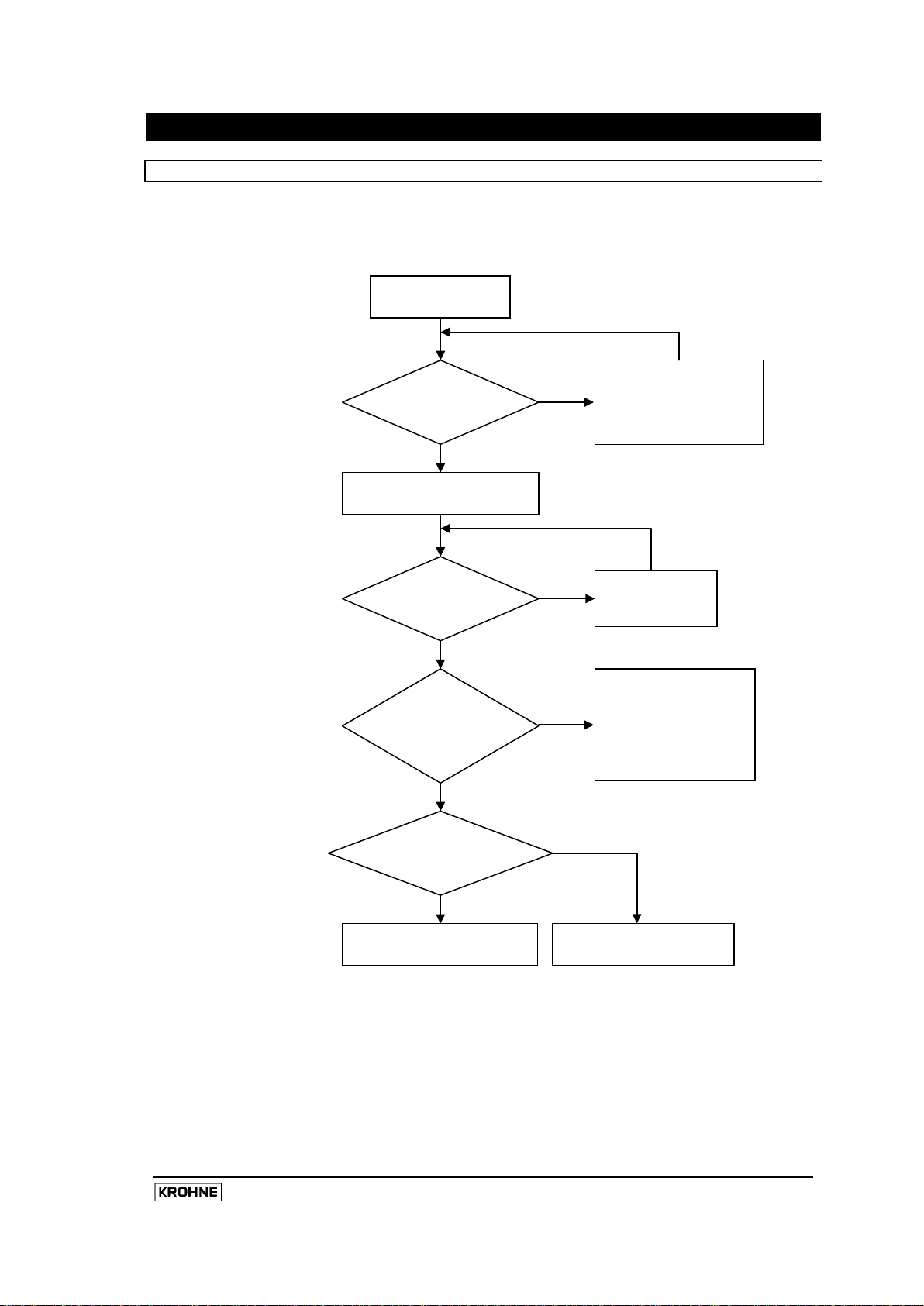
71
Zero Calibration
Error During Calibration
Store Calibration
Zero Cal Percent OK?
Discard Calibration
YES
YES
Calibration In
Set the Process
Initiate Calibration
System State = 3 ?
System State = 6 ?
(Input Reg. 1004)
The System State
NO
YES
YES
NO
NO
NO
8. MFC010 Operations
8.1 Mass Flow Zero Calibration
All KROHNE m ass flow meters are supplied with an ac curate calibration that is performed at the factory
prior to despatch. However, due to process and i nstallation variations that c annot be ac counted for by
factory calibration, it is always good practice to perform regular zero calibrations on the sensor to ensure
the accuracy of the results. The simple process for performing the zero calibration is laid out below.
The new calibration must be stored in memory (set Output R egister 1001) bef ore it will be us ed in t he
Mass F low m easurement r esult. T he Z ero c alibration v alue c an be monitored during the calibration
process by reading the “Zero Calibration Percent” Input Register (Input register No. 3047/3048). This will
provide a floating-point value that represents the zero as a percentage of the nominal flow of the sensor.
During calibration the register will return the actively measured zero. When not calibrating, this register
will indicate the stored calibration value.
Flow to Zero
(Input Reg. 1004)
(Set Output Register 1002)
Error? ( Binary
Reg. 1008 = 1)
(Input Reg. 3047/3048)
(Set Output Register 1001)
(Input Reg 1004)
must be = 3 before
calibration can begin.
Progress
Rectify problem before
re-starting the
calibration (See
Explanations below)
(Set Output Register 1010)
MFC010 Interface Manual
Page 74

72
MFC010 Interface Manual
The “Zero Calibration Status Flag”, held in Binary Input register no. 1008, indicates when the system has
detected an er ror dur ing t he c alibration pr ocess and has s ubsequently abandoned t he c alibration
operation. There are two r easons f or t his t o oc cur. T he f irst w ill oc cur w hen t he f low r ate dur ing
calibration exceeds ±10% of the sensors nominal flow. The second will occur when the system is not in
“Measurement” m ode, dur ing t he c alibration per iod. A t the instant the system mode changes from
“Measurement” the Zero Calibration process will be terminated, this is also the case if the system is not in
“Measurement” mode when the calibration is initiated.
8.2 Density Calibration
Although an accurate calibration of density is performed during the manufacturing process, this factory
calibration is performed on Air and Water and as such covers a large range of possible measurement due
to the wide-ranging applications into which the Optimass sensors are installed. It is always advisable, if
possible, for the user/installer to perform a density calibration on the actual process fluid, preferably at the
two extremes of the process density. T his will provide a m uch greater degree of accuracy for the target
application process.
The U ser c an c hoose t o per form ei ther a “ One poi nt” or “Two point” c alibration. T he “ Two poi nt”
calibration i s bes t to be us ed when t here ar e t wo c learly def ined process densities, the single point is
more appropriate when there is one, or a less clearly defined or narrow range of process densities. The
procedure f or t he “ One poi nt” and “ Two poi nt” c alibrations i s v ery m uch t he s ame, t he “ Two poi nt”
calibration merely being a case of repeating the “Single point” calibration, though the user should note
that the output status registers used to initiate the “One point” and “Two point” calibrations are different (
see section 7.2 ).
The User can choose to use one of three preset product types (see Holding Register No 1028) for which
the system will use internally programmed polynomials to determine the correct density at the measured
process t emperature. Alternatively the user can select the fourth product type, “Other”, and enter a
density value i nto t he c alibration dens ity hol ding r egister ( see H olding R egister N o 3093) . D uring t he
calibration pr ocess t he s ystem w ill measure the tube par ameters f or t he s elected pr ocess dens ity and
temperature and store them for use in the measurement algorithms.
Should it be necessary the user can elect to restore the original factory calibration values by selecting
output r egister num ber 1014 . T he us er m ust t hen s ave t he r estored configuration to the non-volatile
memory by selecting output register number 1001.
When a “ One poi nt” c alibration i s performed for t he f irst t ime, t he M FC010 w ill r eplace t he f actory
calibrated “Empty” value with the new user calibration value. Subsequently, the MFC010 will use the
newly calibrated value to replace the calibration value that is the closest to it.
NB. The OPTIGAS 5000 meter does not measure density, so any attempt to perform a density calibration
will be rejected and will result in an error condition in the density status.
Page 75

73
Set the Process
Density
Set the Product type
Product Type = 3 ?
YES
NO
Set the Density Value
Start Single Point
(Set Output Reg. 1011)
Density Calibration
(Input Reg 1007)
YES
NO
Error During Density
Calibration (See notes)
Store Calibration
The procedure for performing a single point density calibration is as follows.
An er ror flag is set in the “Density Calibration” input status register when the m easured t ube frequency
does not c orrelate with the value/product type of the calibration density entered by the user ( e.g. if the
user requests a calibration of the “Air” type when the tube is full of process fluid.)
(Holding Reg. 1028)
(Holding Reg. 3093)
Calibration
Status = 1 ?
(Set Output Register 1001)
MFC010 Interface Manual
Page 76

74
MFC010 Interface Manual
Set the Process
Point
Set the Product type
Product Type = 3 ?
YES
Set the Density Value
Start Two Point
(Set Output Reg. 1012)
YES
NO
Error During Density
ibration (See notes)
Set the Process
Second Point
Set the Product type
Density Calibration
(Input Reg 1007)
NO
The procedure for performing a two point density calibration is as follows.
Density for the First
(Holding Reg. 1028)
Calibration
Status = 1 ?
Density for the
(Holding Reg. 1028)
(Holding Reg. 3093)
Cal
Page 77

75
Product Type = 3 ?
YES
Set the Density Value
Continue Two Point
(Set Output Reg. 1013)
YES
Error During Density
Calibration (See notes)
Store Calibration
Density Calibration
(Input Reg 1007)
NO
NO
(Holding Reg. 3093)
Calibration
Status = 1 ?
(Set Output Register 1001)
8.3 Fixed and Referred Density Operation
In addition to t he di rectly m easured D ensity, t he M FC010 pr ovides t he us er w ith t wo f urther m odes of
Density determination. These can be selected by setting the appropriate Density Mode value in Holding
register no. 1019 (see s ection 7.5 on page 49). N B. T he system w ill always use the ac tual measured
density in the determination of the mass flow reading, regardless of the Density Mode setting.
The Fixed Density is used when direct density measurement is not required, to calculate the Volume and
other density related measurement values. It can also be used to test Density related features such as
the Internal Process control Mechanism (see section 8.8 on page 78). When the Density Mode is set to
“Fixed” t he value of the density is determined by the contents of the Fixed density register, accessed as
Holding register no. 3057/ 3058 (see section 7.5 on page 49). This value i s s caled ac cording t o t he
setting of the Density units, accessible as Holding Register no. 1021 (see section 7.5 on page 49).
In Referred Density mode, the MFC010 will extrapolate the measured density to a reference temperature
based on a defined slope relationship. The reference temperature is set in Holding register no.
3055/3056 and is scaled to the Temperature units, which ar e s et i n H olding r egister N o. 1025 . T he
reference s lope i s def ined i n H olding r egister 3059/ 3060 and i s s caled by D ensity U nits/Temperature
Units, e.g. g/cm
For example, given a density of 1.233 g/cm
37.8°C, if the density is referred back to 20°C using a slope of 0.025 g/cm
will be ( 37.8 – 20 ) x 0.025 + 1.233 = 1.678 g/cm
equated to a density of 1.678 g/cm
3
/°C.
3
at 20°C.
3
is measured by the sensor at a process temperature of
3
. i.e. a measured Density of 1.233 g/cm3 at 37.8°C is
3
/°C then the displayed density
MFC010 Interface Manual
Page 78

76
MFC010 Interface Manual
8.4 Concentration Measurement
Using the density and temperature measurement data the MFC010 is able to calculate the concentration
of a num ber of s tandard and us er def ined pr ocess m ixtures. T his ex tra facility must be purchased in
addition to the standard MFC010 software functionality. Consult the Optimass support team for details.
When the c oncentration f eatures ar e ena bled, t he us er w ill be pr ovided w ith a c omplete m anual t hat
covers all of t he as pects of c oncentration m easurement i n t he O ptimass s eries of s ensors. T his
concentration manual was written in relation to the MFC050 converter but can equally be applied to the
MFC010 as the functionality is the same. Along with the concentration manual the user will be pr ovided
with a s oftware appl ication t hat w ill aut omatically c alculate t he r equired c oefficients f rom pr ocess data
supplied by the user.
To enable the concentration measurement the user must write the unique sensor specific password value
to H olding r egister num ber 7007/ 7008. (the value i s a l ong integer and s o m ust be w ritten as t wo
registers). The correct password value will be supplied by KROHNE upon pur chase of the Concentration
option. The lockout operation of the Concentration password is the same as described for the Supervisor
passwords described below.
8.5 Using the System Protection Passwords
The M FC010 i s pr otected by a s eries of f eatures t o pr event ac cidental or inadvertent alteration of the
configuration and c alibration s ettings. T he “ Supervisor” pas sword, when activated, blocks all write
operations t o t he H olding r egisters. T he “ Service” pas sword, when ac tivated, w ill b lock a ll w rite
operations to any Holding register that directly affects the measurement values, principally the calibration
coefficients. Registers that are protected by the “Service Password” are indicated in the Holding Register
definitions with the symbol, refer to Section 7.5.
The “Service” password is always active when power is first applied to the MFC010. It can be disabled for
2 minutes by writing the correct code to the “Service” password register, Holding register No 1002. The
status of t he “ Service” pas sword c an be det ermined by examining the c ondition of I nput B inary s tatus
register num ber 1002. If t he password register is written to bef ore the 2 m inute period of de-activation
expires, t hen the 2 m inute count will be restarted. The “Service” password is a fixed 16 bit code which
may be obtained if necessary from the Optimass product support team, refer to your supplier for details.
The “Service” password cannot be read from the Holding register, the MFC010 will return a “0” value when
the “Service” password register is read.
The Supervisor password is by default de-activated. I t can be ac tivated by writing an appr opriate 16 bi t
value t o t he “ Supervisor” pas sword r egister, H olding r egister N 0 1001. The s tatus of t he “ Supervisor”
password can be determined by examining the condition of Input Binary status register number 1001. To
de-activate the “Supervisor” password simply write the chosen password back to the “Supervisor”
password register. The password protection will become effective as soon as the password is written, but
the us er m ust r emember t o per form a “ Save t o E EPROM” t o ens ure t hat t he pas sword condition is
reloaded when the unit is next switched on. When activated the “Supervisor” password register will return
an encoded version of the password value when read. If the password is forgotten or otherwise
incorrectly recorded, the system can be unlocked by sending the encoded value to the Optimass product
support team who will provide the correct password value, refer to your supplier for details.
Writing an incorrect value to a password register on three consecutive occasions will result in a 10 minute
“lockout” of that register, i.e. subsequent writes to that register, whether with the correct password or not,
will be r ejected with an “ Illegal Function” error response. See Section 5.6 on page 22 for details of the
error response telegram formats.
Page 79

77
8.6 Saving and Restoring Configuration settings
The c ontents of the holding registers (see section 7.5 on page 49 ) are stored in non-volatile EEPROM
memory such that when power is applied t o t he M FC010 t he pr evious c onfiguration s ettings w ill be
reloaded. When changing the settings of the holding registers the user must command the MFC010 to
save the changes (using Output State Register No 1001, See section 7.2 on page 39 for details), before
they are saved to the non-volatile memory. The altered values must be saved before they will affect the
measurement values.
The Units settings and User defined unit scaling values are the exception to this rule, they will affect the
transmitted v alue as s oon t hey ar e c hanged. T he c hanges m ust still be stored in the non-volatile
EEPROM memory if they are to be restored on the next occasion that the MFC010 is switched on.
When changes have been made to the configuration but not stored in the non-volatile EEPROM memory
the system will indicate this fact by setting the “Parameters Changed” flag, which can be interrogated by
using command 7 (see section 6.7 on page 29 ) or accessing Input State register No. 1004 ( see section
7.3 on page 41 ). This flag will be reset once the command to store the settings is acted upon.
The us er can elect to discard the settings that have been written to the MFC010 i f t hey have not been
saved to the non-volatile EEPROM memory, in which case the previously stored settings will be reloaded
from the non-volatile EEPROM memory. This is in effect the same as switching the MFC010 off and back
on again. To discard the settings use Output State register No .1010 (see s ection 7.2 on page 39 for
details).
It is also nec essary t o s ave t he t otalisers ( using O utput S tate R egister N os. 1015 or 1016) , t o ensure
actual totaliser values are recalled in case of power loss.
8.7 Implementing User Defined Units
In order to provide a degr ee of flexibility for the Modbus interface when using the MFC010, a f acility has
been i ncluded t o al low t he oper ator t o s cale t he t ransmitted v alues t o an oper ator def ined uni t i f t he
required units are not included in the list of standard units for each variable ( see Holding Registers 1020
– 1026 ). To use the User Defined units simply set the units register for the required variable to “0” then
write the required scaling factor to the appropriate register from Holding Register No 3083 to 3091. The
scaling f actor w ill rescale the transmitted value from t he i nternal M FC010 units ( see bel ow) to the user
defined scale. NB Be careful as this w ill change t he s caling of all r elated variables that use the same
units.
Internal Units : Mass Total g, grammes
Mass Flow g/s, grammes per second
Density g/cm
Volume Total cm
Volume Flow cm
3
, grammes per centimetre cubed
3
, centimetres cubed
3
/s, centimetres cubed per second
For ex ample, if the user wished to r eceive t he transmitted Volume Total in “cubic yards” then the value
stored in Holding register No 3085 should be 1.30795 x10
-6
x10
yd3).
-6
( i.e. 1yd3 = 764554.9 cm3, so 1cm3 = 1.30795
MFC010 Interface Manual
Page 80

78
MFC010 Interface Manual
8.8 Using the Internal Process Control Mechanism
The internal process control system permits t he us er t o l imit t he m easurement w hen t he pr ocess
conditions are outside of the prescribed limits as defined in the Internal Process Control settings.
The p rocess c onditions under w hich t he c ontrol m echanism i s em ployed ar e def ined in the holding
registers ( s ee s ection 7.5 on page 49 ). H olding r egister N o.1010 determines the source of t he
controlling variable, i.e. the process t emperature or t he pr ocess dens ity. T he c ontents of H olding
registers 3051 and 3053 determine the minimum and m aximum limits of the controlling variable, outside
of which the process control mechanism will be applied.
When applied, the process control mechanism will perform one of three functions, defined by the setting
of Holding register no 1009.
Holding Register 1009 = 1 : The Internal Process control mechanism is disabled
Holding Register 1009 = 2 : The Flow readings are forced to zero
Holding Register 1009 = 3 : The Flow readings are forced to zero and all of the totalisers are reset.
When the Internal Process control mechanism is active, i.e. the defined process condition is beyond the
set limits, the “Process control active” bit in the Exception Status message (see section 6.7 on page 29)
will be set. This status bit is also accessible in Discrete Input register no. 1009 (see section 7.3 on page
41).
8.9 Custody Transfer Applications
To provide added security for use in C ustody t ransfer appl ications t he MFC010 has been des igned t o
include a C ustody T ransfer Password. T his pas sword w ill pr event any c hanges t o t hose configuration
variables (Holding registers) that have any effect on t he measurement result. T he Custody password is
activated by writing a 16-bit password value of the user’s choice to the Custody transfer password register
(Holding Register No. 1003). W hen the Custody Transfer protection is activated it will be indicated in the
Binary Input register Number 1003. Those configuration variables that are write protected by the Custody
Transfer Password are indicated with the symbol CT in the Register definitions. The Custody transfer
protection also extends to the resetting of certain Error flags, see section 9 for details.
Writing an incorrect value to a password register on three consecutive occasions will result in a 10 minute
“lockout” of that register, i.e. subsequent writes to that register, whether with the correct password or not,
will be r ejected with an “ Illegal Function” error response. See Section 5.6 on page 22 for details of the
error response telegram formats.
Page 81

79
8.10 Pressure Suppression
The Pressure Suppression feature has been included to permit the user to eliminate any influences on the
measurement result of sudden termination of flow, such as when a valve is shut. W hen this occurs the
propagation of pressure waves along the pipe work and through the meter may produce an “Over-shoot”
or “ringing” effect, where the flow rate will oscillate backwards and forwards until it settles to a stable zero
flow condition, as is indicated in the diagram below.
The amplitude and duration of the “Ringing” in proportion to the flow rate in the diagram above has been
greatly ex aggerated to pr ovide a c lear indication of what may oc cur. I t appears at first glance that the
positive and negat ive variations would cancel each other in any totaliser result, however, as the result is
decaying t he negat ive peak s w ill al ways be s lightly l arger t han t he pos itive peaks and will therefore
accumulate a negative error in any totaliser result. This will of course become a positive error when the
flow is in the opposite (negative) direction.
In most cases the amplitude of the ringing will be below the “Low Flow Threshold” (see Holding Register
No 3047) and will therefore not influence the result. However, in some cases the amplitude of the ringing
will be above the Low Flow Threshold and will still contribute to an error in the totaliser values (see figure
below).
MFC010 Interface Manual
Page 82
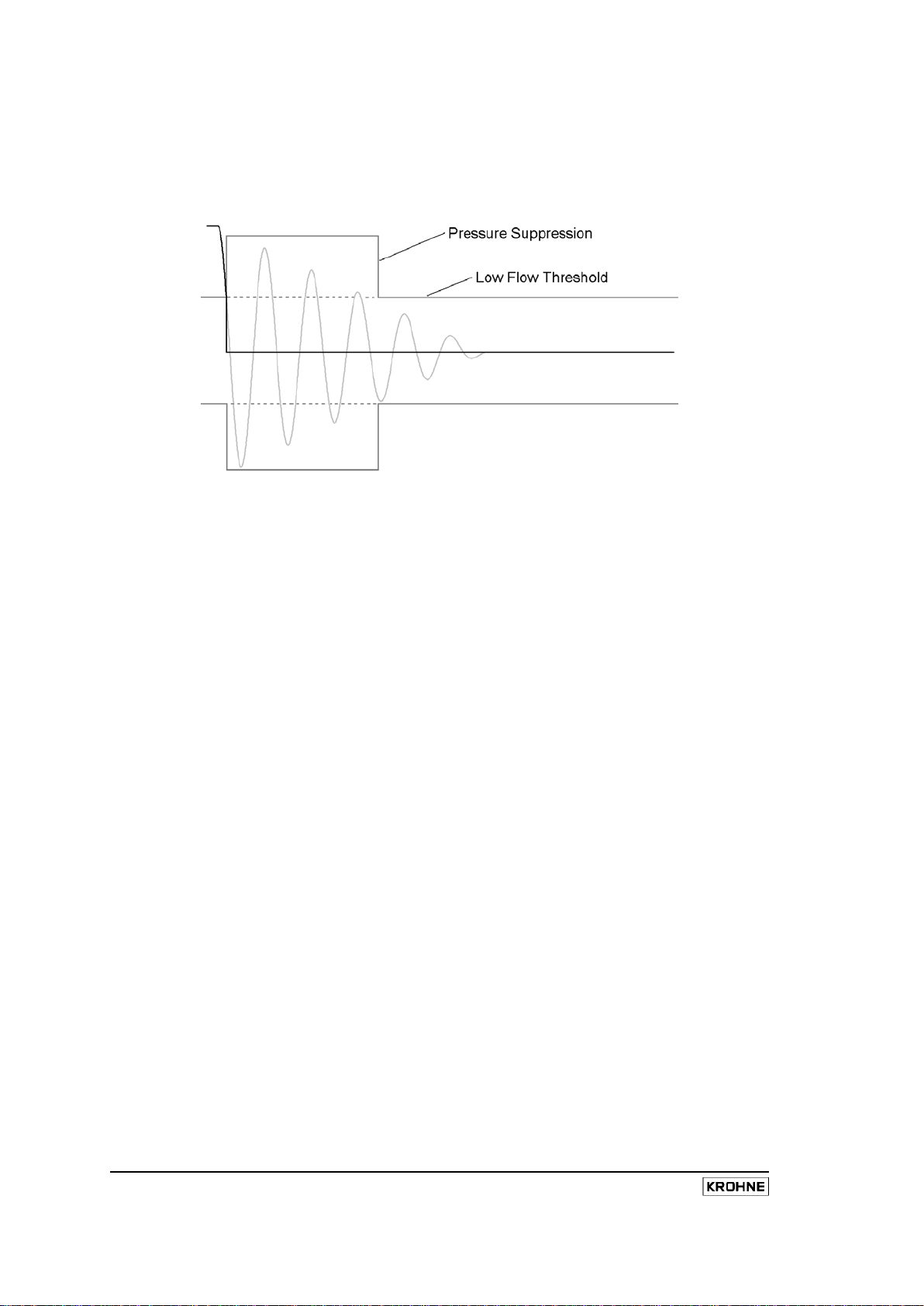
80
MFC010 Interface Manual
The Pressure Suppression function eliminates the effect of this over-shoot by increasing the “Low flow
Threshold” for a short period of time. The pressure suppression function will be triggered when the flow
rate first falls below the low flow threshold. For a set period of time, defined in Holding Register No 3101,
the Pressure suppression threshold, defined in Holding Register No. 3103, will be added to the level of the
Low flow threshold, as defined in Holding Register No. 3047. See figure below.
The amplitude, frequency and dec ay rate of the ringing effect will depend upon t he flow rate prior to the
Flow “ Switch Off”, the r ate at which the “Switch Off” occurs and the damping characteristics of the pipe
work i nstallation. F or t his r eason, s etting t he par ameters of the Pressure Suppression function is an
empirical process that the installer must go through to optimise the operation to the target installation.
Page 83

81
9. Error and Warning Messages
The error and warning flags generated by the MFC010 can be retrieved from Input register numbers 7001
to 7008. The Error and warning flags are split into two pairs of 32 bit long integer values (each filling two
registers locations).
Some of t he f ollowing E rror and W arning f lags ar e pr otected f rom bei ng r eset i n Custody transfer
applications when the custody transfer password is ac tivated, t hese ar e i ndicated bel ow by t he CT
symbol.
9.1 System Errors
The System Error flags, held as a long integer value in input registers 7001/7002, are an indication of
faults or malfunctions that are present at that moment in the sensor or Front End electronics systems.
Input registers 7005/7006 hold a stored history of which these error flags have been set since the last
“Reset” command, which can be used to monitor and record the occurrence transient error conditions.
(See Output Coil Number 1008 on page 39 for details of how to reset the stored Error Flags).
Bit Error Flag Designation
0
CT
1
CT
2
CT
3
CT
Name : ROM Error
Cause : Internal integrity checking by the MFC010 processor has detected a
corruption of the main program code memory. Such an error could
lead to a serious malfunction of the MFC010.
Action : Switch off the MFC010 immediately, do not re-use this unit until the
problem is resolved. Call a service support engineer.
Name : RAM Error
Cause : Internal integrity checking by the MFC010 processor has detected
a corruption of the main program data memory. Such an error
could lead to a serious malfunction of the MFC010.
Action : Switch off the MFC010 immediately, do not re-use this unit until
the problem is resolved. Call a service support engineer.
Name : EEPROM Write Error
Cause : The MFC010 processor is having problems saving configuration
data to the onboard non-volatile memory.
Action : The unit can continue to be used until a service support engineer
is able to attend, as long as no further configuration changes are
required. See Section 8.6 on page 77 for details of saving the
configuration to the non-volatile memory.
Name : EEPROM Data Corrupted
Cause : The configuration settings stored in the non-volatile EEPROM
memory have been corrupted, the default values have been
restored to prevent a unit malfunction due to invalid settings.
Action : Re-check all of the configuration settings and if necessary reset to
previous values. If this error is repeated persistently, call a
service support engineer.
MFC010 Interface Manual
Page 84

82
MFC010 Interface Manual
Bit Error Flag Designation
4
CT
5
CT
6
CT
7
CT
8
CT
Name : PCB Temperature
Cause : The temperature detected on the main circuit board of the
MFC010 is exceeding the maximum limit specified for the
electronic components fitted to it.
Action : This error may be due to a component malfunction on the main
MFC010 circuit board, incorrect wiring or excessive process
temperatures.
Check that the process temperature is within the specified limits
of the sensor being used. The temperature history, held in
Input register No. 1004 (see section 7.4 on page 43 for details),
will indicate the maximum process temperature that has been
measured.
Check that the system is correctly connected, excessive power
input to the MFC010 could lead to increased heat build up and
subsequent component failure.
If none of the other causes above can be attributed to be the
source of the error, call a service support engineer for further
guidance.
Name : Internal Voltage Levels
Cause : The Voltage levels within the main measurement circuits are
outside of normal operating limits.
Action : No field maintenance can be performed to rectify this problem, the
MFC010 should be replaced immediately. Call a service support
engineer.
Name : Temperature Sensor Short Circuit
Cause : The measurement system has detected an electrical short circuit
between its temperature input terminals, therefore temperature
measurement is not possible. The system will default to a static
temperature reading of -200°C when this error occurs, however,
internally it will use the calibration reference temperature for
measurement calculation to prevent sudden massive variation in
the mass flow or density measurements.
Action : Check for short circuits between the Temperature sensor
connections on the back plane circuit board and between the
temperature sensor connection and the sensor case. Call
a service support engineer for further advice.
Name : Temperature Sensor Open Circuit
Cause : The measurement system has detected an electrical open circuit
between its temperature input terminals, therefore temperature
measurement is not possible. The system will default to a static
temperature reading of +500°C when this error occurs, however,
internally it will use the calibration reference temperature for
measurement calculation to prevent sudden massive variation in
the mass flow or density measurements.
Action : Call a service support engineer
Name : MT Strain Gauge Short Circuit
Cause : The measurement system has detected an electrical short circuit
between its measuring tube strain gauge input terminals,
therefore strain measurement is not possible. The system will
default to a static strain reading of 0Ω when this error occurs,
however, internally it will use the calibration reference strain for
measurement calculation to prevent sudden massive variation in
the mass flow or density measurements.
Action : Call a service support engineer
Page 85

83
Bit Error Flag Designation
9
CT
10
CT
11
CT
12
CT
13
CT
14
CT
15
CT
16
CT
Name : MT Strain Gauge Open Circuit
Cause : The measurement system has detected an electrical open circuit
between its measuring tube strain gauge input terminals,
therefore strain measurement is not possible. The system will
default to a static strain reading of 1000Ω when this error occurs,
however, internally it will use the calibration reference strain for
measurement calculation to prevent sudden massive variation in
the mass flow or density measurements.
Action : Call a service support engineer
Name : IC Strain Gauge Short Circuit
Cause : The measurement system has detected an electrical short circuit
between its inner cylinder strain gauge input terminals, therefore
strain measurement is not possible. The system will default to a
static strain reading of 0Ω when this error occurs, however,
internally it will use the calibration reference strain for
measurement calculation to prevent sudden massive variation in
the mass flow or density measurements.
Action : Call service support engineer
Name : IC Strain Gauge Open Circuit
Cause : The measurement system has detected an electrical open circuit
between its inner cylinder strain gauge input terminals, therefore
strain measurement is not possible. The system will default to a
static strain reading of 1000Ω when this error occurs, however,
internally it will use the calibration reference strain for
measurement calculation to prevent sudden massive variation in
the mass flow or density measurements.
Action : Call service support engineer
Name : Sensor A
Cause : The measured level of Sensor A is below 5% of the required value.
This error can occur for short periods following rapid changes of product
density, such as when the tube changes to or from an empty state or
when excessive Air bubbles are present in the product.
Action : If this Error is persistently reported during normal operation call your
service support engineer for further advice.
Name : Sensor B
Cause : The measured level of Sensor B is below 5% of the required value.
This error can occur for short periods following rapid changes of product
density, such as when the tube changes to or from an empty state or
when excessive Air bubbles are present in the product.
Action : If this Error is persistently reported during normal operation call your
service support engineer for further advice.
Name : Ratio A/B
Cause : The ratio of the two sensor signals is too large, i.e. one of the
motion sensors is giving a reading significantly below the other
sufficient to cause an error in the mass flow calculations. This
may be caused by or the cause of instability in the tube oscillation
control system.
Action : Call service support engineer
Name : DC A
Cause : The DC component of the motion Sensor A signal is too large.
Action : Call service support engineer.
Name : DC B
Cause : The DC component of the motion Sensor B signal is too large.
Action : Call service support engineer.
MFC010 Interface Manual
Page 86

84
MFC010 Interface Manual
Bit Error Flag Designation
25
28
17
CT
18
CT
19
CT
20
21
22
CT
23
Name : Drive System Open Circuit
Cause : The tube oscillation control system has detected an open circuit in
the connection the to tube drive coil.
Action : Call service support engineer.
Name : Drive System Short Circuit
Cause : The tube oscillation control system has detected an short circuit in
the connection to the tube drive coil.
Action : Call service support engineer.
Name : Front End Amplifier Failure
Cause : The measurement system has detected a failure in the motion
sensor interface circuit.
Action : Switch off the unit immediately to prevent damage to the sensor.
This cannot be repaired in the field, the Front End electronics must be
replaced. Call a service support engineer.
Name : Harmonic Distortion of Sensor A
Cause : Not Currently Implemented
Action : Call service support engineer
Name : Harmonic Distortion of Sensor B
Cause : Not Currently Implemented
Action : Call service support engineer
Name : Watchdog Reset Event
Cause : Not Currently Implemented
Action : Call service support engineer
Name : Reserved for Future Use
24
26
27
29
30
31
Name : Reserved for Future Use
Name : Reserved for Future Use
Name : Reserved for Future Use
Name : Reserved for Future Use
Name : Reserved for Future Use
Name : Reserved for Future Use
Name : Reserved for Future Use
Name : Reserved for Future Use
Page 87

85
9.2 Process Warnings
The Process Warning flags, held as a long integer value in input registers 7003/7004, are an indication of
process conditions that are present at that moment that may adversely affect the measurement operation
or accuracy of the mass flow sensor, such as exceeding the specified operating limits of the sensor. Input
registers 7007/7008 hold a stored history of which these warning flags hav e been s et s ince t he l ast
“Reset” command, which can be used to monitor and record the occurrence of transient process warning
conditions. (See Output Coil Number 1009 on page 39 for details of how to reset the stored Error Flags).
Bit Warning Flag Designation
0
CT
1
CT
2
CT
3
CT
4
CT
5
6
7
Name : Mass Flow Over-range
Cause : The measured mass flow is beyond the maximum allowable limit
for this sensor
Name : Process Temperature Outside Limits
Cause : The measured tube temperature has been outside of the
permissible operating limits of the sensor.
Name : Process Density Over-range
Cause : The product density is beyond the allowable limits of the system
to enable accurate measurement
Name : Mass Totaliser Over-flow
Cause : The Mass total value has overflowed, i.e. the mass total variable
has previously reached its maximum permissible value and
therefore has been forced to return to zero after the following
increment.
Name : Volume Totaliser Over-flow
Cause : The Volume total value has overflowed, i.e. the Volume total
variable has previously reached its maximum permissible value
and therefore has been forced to return to zero after the following
increment.
Name : Additional Totaliser Over-flow
Cause : The Additional total value has overflowed, i.e. the Additional total
variable has previously reached its maximum permissible value
and therefore has been forced to return to zero after the following
increment.
Name : Concentration By Mass Totaliser Over-flow
Cause : The Concentration Total - By Mass value has overflowed, i.e. the
Concentration Mass total variable has previously reached its
maximum permissible value and therefore has been forced to
return to zero after the following increment.
Name : Concentration By Volume Totaliser Over-flow
Cause : The Concentration Total – By Volume value has overflowed, i.e.
the Concentration Volume total variable has previously reached
its maximum permissible value and therefore has been forced to
return to zero after the following increment.
MFC010 Interface Manual
Page 88

86
MFC010 Interface Manual
Bit Warning Flag Designation
19
22
25
8
9
10
CT
11
CT
12
CT
13
14
15
16
17
18
Name : Zero Flow Calibration Above Limits
Cause : The Mass flow rate during the previous Mass flow zero calibration
attempt was above 10% of the nominal flow or this sensor.
Name : Zero Flow Calibration Failed
Cause : The previous Mass flow zero calibration failed. Refer to section
8.1 on page 71 for further details.
Name : Temperature Drift
Cause : The measured temperature has exceeded ±30°C from the
temperature reference taken during the last Mass Flow zero
calibration. For use in Custody transfer applications.
Name : Power Fail
Cause : This flag is set when the system is started to indicate that the
power supply has been interrupted.
Name : Sampling
Cause : The tube oscillation control system has had difficulty locking onto
the tube drive frequency, which may have resulted in inaccurate
measurement values.
Name : 2 Phase Signal Above Limit
Cause : 2 phase signal is above the threshold limit set
Name : Tube Asymmetry
Cause : Not Currently Implemented
Name : External Vibration
Cause : Not Currently Implemented
Name : Pulsating Flow
Cause : Not Currently Implemented
Name : Partially Empty System
Cause : Not Currently Implemented
Name : Reserved for Future Use
20
21
23
24
Name : Reserved for Future Use
Name : Reserved for Future Use
Name : Reserved for Future Use
Name : Reserved for Future Use
Name : Reserved for Future Use
Name : Reserved for Future Use
Name : Reserved for Future Use
Page 89

87
Bit Warning Flag Designation
27
26
Name : Reserved for Future Use
Name : Reserved for Future Use
28
29
30
31
Name : Reserved for Future Use
Name : Reserved for Future Use
Name : Reserved for Future Use
Name : Reserved for Future Use
MFC010 Interface Manual
Page 90

88
MFC010 Interface Manual
10. Trouble Shooting
The following are some examples of common problems caused by incorrect installation or operation of the
MFC010. Check these before contacting service support.
10.1 “No Response to Modbus Requests”
There are a number of possibilities as to why no response would be received from the MFC010. Here is a
list of some of the more obvious things to check.
a) Check is that there is an appropriate voltage input on the V+ and V- terminals of the MFC010.
(See section 3.1 on page 6 for the power input parameters).
b) Ensure t hat t here i s c ontinuity bet ween t he A and B i nput terminals and their as sociated
terminals at t he m aster c ontrol dev ice. C heck t hat A and B ar e connected correctly as
indicated i n s ection 3.3. Ensure that there i s a pr oper “ Common” c onnection bet ween t he
master dev ice and t he MFC010. W hen us ed i n H azardous ar eas t he in-line resistance and
capacitance of any barrier devices may prevent communication if not specified and installed
properly (Refer to section 4 for further details).
c) The MFC010 will ignore messages that are not addressed to it, or any message that contains
fundamental formatting errors. So, check that the Address ID that is being requested is correct,
the def ault value i s 1. C heck t hat t he transmission r ate ( default = 19200 B aud) and format
(default = 8 data bits, Even parity and 1 stop bit) are correct. (See section 5 on page 19 for the
transmission format details).
10.2 “Communication Errors”
Intermittent communication errors can have a num ber of causes, almost all of which can be attributed to
the quality of the connection between the Master device and the MFC010, such as
a) Low quality connections at the terminals of the MFC010 or Master Device, ensure that good
contact is being made and that the connections are not frayed or corroded.
b) Cable lengths and/or cable capacitance are too great for the data rates being used.
c) Powerful sources of electromagnetic interference in close proximity to the path of the cable
route, refer to the installation guidelines in section 3.5 on page 12.
d) It is common to use converter devices to connect the Modbus RS485 output of the MFC010 to
the serial RS232 port or USB port of a host PC using off-the-shelf protocol converters. Many
of these, especially USB based converters will have problems operating the Modbus Interface
as it is a timing critical protocol. Where possible, a dedicated RS485 interface PC card should
be used.
Page 91

89
10.3 “The MFC010 is responding with an Illegal Modbus Function Message”
There can be two reasons why this error response will be returned by the MFC010 in answer to a request.
a) The F unction bei ng r equested i s not valid f or t he M FC010, c heck t he l ist of v alid M odbus
functions in section 6 on page 23.
b) An attempt is being made to write to a password protected holding register. The password must
be de-activated before an attempt to write to the register is made. All registers are protected by
the Supervisor password when it is active. T hose registers that are protected by the Service or
Custody Transfer passwords are indicated in the relevant sections of this document, see section
7.1 on page 33 for a s ummary. S ee s ection 8.5 on page 76 and section 8.9 on page 78 for
further details on the operation of the passwords.
10.4 “The MFC010 is responding with an Illegal Data Message”
When the MFC010 responds with an “Illegal data message”, it is because the value being written t o a
holding register in the MFC1010 is beyond the permitted limits for that register, the limits for each holding
register are indicated in section 7.5.
10.5 “The MFC010 is responding with an Illegal Address Message”
There are four reasons why the MFC010 will return an “ Illegal Address” error message when the Master
device makes a request.
a) The register address being requested is not supported by the MFC010, check the requested
register against the register summary in section 7.1.
b) Although the Start address is valid, when accessing multiple registers the number of registers
requested may extend beyond the end of t he v alid addr ess r ange f or t hat gr oup of v ariables.
Check the number of variables requested and ensure that the last register address is valid.
c) The number of registers requested is not correct for the data type being requested. For example,
if registers containing floating point variables are r equested t hen t he num ber of r equested
registers m ust be a m ultiple of 2 as t he f loating poi nt v ariables ar e hel d i n t wo c onsecutive
registers. For Double precision floating point variables the num ber of registers requested must
be a multiple of 4.
d) From “c” above, the system will respond with an “Invalid Address” error when an attempt is made
to ac cess t he as sociated r egisters of a m ulti-register variable, f or example when access to the
second register of a f loating point variable is attempted. i.e. if an attempt is made to access
Input register 3002, which contains the second half of the variable accessed by Input register
3001.
MFC010 Interface Manual
Page 92

90
MFC010 Interface Manual
Appendix A : Modbus CRC Checksum Calculation
The Procedure for calculating the CRC checksum for a Modbus Telegram is as follows (copyright
Modbus-IDA).
1. Load a 16-bit register with FFFF
. This is the CRC register
16
2. Exclusive OR the first byte of the telegram with the low-order byte of the CRC, placing
the result in the CRC register
3. Shift the CRC register one bit to the right (toward the LSB), zero-filling the MSB. Extract
and examine the LSB.
4. If the LSB of the CRC result was 0 : Repeat Step 3 ( another shift)
If the LSB of the CRC result was 1 : Exclusive OR the CRC register with the polynomial
value A001
( 1010 0000 0000 00012 ).
16
5. Repeat steps 3 and 4 unt il 8 s hifts hav e been per formed. W hen t his i s done, a
complete 8-bit byte will have been processed.
6. Repeat steps 2 through 5 for the next 8 bit character of the message. Continue doing
this until all of the characters in the message have been processed.
7. The final resulting value held in the CRC register is the CRC Checksum value.
The result is a 16 bi t “Unsigned Integer”. T he Least Significant byte of the checksum result is placed in
the first of the telegram CRC characters, the Most significant byte is placed in the second of the telegram
CRC c haracters, t he ov erall l ast c haracter i n t he t elegram. S ee S ection 3. 1 f or t he t elegram f ormat
details. Refer to the Modbus Protocol Reference Guide for more details on calculating the telegram CRC
value.
The following routine, written in the ‘C’ programming language, demonstrates the method for calculating
the checksum.
Page 93

91
unsigned short Calculate_Checksum (unsigned char uc_Telegram_Length, unsigned short *Buffer_Pointer )
{
// Declare Local Variables
unsigned char uc_Byte_Loop;
unsigned char uc_Bit_Loop;
unsigned short us_Temporary_Checksum;
// Initialise the checksum value
unsigned short us_Checksum = 0xFFFF;
// Loop through each byte of the telegram Buffer
for (uc_Byte_Loop = 0; uc_Byte_Loop < uc_ Telegram_Length; uc_Byte_Loop++)
{
// XOR the newly indexed buffer location with the current value of the checksum
us_Checksum ^= (*(Buffer_Pointer + uc_Byte_Loop) & 0x00FF);
// Perform an 8 bit rotation and Polynomial addition on the checksum
for(uc_Bit_Loop = 0; uc_Bit_Loop < 8; uc_Bit_Loop++)
{
// Store the current value of the checksum in a temporary local variable
us_Temporary_Checksum = us_Checksum;
// Right shift the Checksum by one bit
us_Checksum >>= 1;
// Was the first bit of he checksum set?
if (us_Temporary_Checksum & 0x0001)
{
// If so, XOR the Checksum with the Polynomial value
us_Checksum ^= 0xA001;
}
}
}
// Return the calculated checksum result
return us_Checksum;
}
MFC010 Interface Manual
Page 94

92
MFC010 Interface Manual
Decimal
Binary2
Hexadecimal16
0
0000 0 1
0001 1 2
0010 2 3
0011 3 4
0100 4 5
0101
5
7
0111 7 8
1000 8 9
1001 9 10
1010 A 11
1011 B 12
1100 C 13
1101 D 14
1110 E 15
1111
F
Appendix B : Hexadecimal and Binary Notation
The Binary ( Base 2 ) and H exadecimal ( Base 16 ) mathematical notations are more commonly used in
computer systems because they can be used to more easily represent the digital values involved. Within
this document Binary numbers are indicated by a s ubscript “2” appended t he number, e.g. 10101
Hexadecimal numbers are indicated by a subscript “16” appended to the number, e.g. E45F
16
, and
2
.
Where decimal numbers are represented using the digits 0 to 9, binary numbers are represented using
the digits 0 to 1, and hexadecimal numbers are represented using the digits 0 to 9 and A to F. i.e.
6 0110 6
As with decimal numbers, the most significant, MS, digit of a Binary or Hexadecimal number is on the left
of the number and the least significant, LS, digit is on the right. e.g. for the decimal number 34567, the MS
digit is 3 and the LS Digit is 7.
The standard data representation within computer systems is the “Byte” which consists of 8 binary digits,
or “bits”. Each byte, being 8 bits long can easily be represented as two Hexadecimal digits.
e.g. F F
3 A
Hexadecimal = 1111 11112 Binary = 255 Decimal
16
Hexadecimal = 0011 10102 Binary = 58 Decimal
16
The “Bits” of a byte are indexed from the LS bit, which is bit 0 up t o the MS bit which is bit 7. E ach bit
represents a value of 2
an 8 bit binary value of 00110010
of the bits of an 8 eight bit binary value set, the result will be 2
7
+ 2
= 1 + 2 + 4 + 8 + 16 + 32 + 64 + 128 = 255).
index
, such that bit 7 represents 27 = 128, and bit 3 represents 23 = 8 and so on. So
is equal to a decimal value of 21 + 24 + 25 = 2 + 16 + 32 = 50. With all
2
8
– 1 = 255 (20 + 21 + 22 + 23 + 24 + 25 + 26
When representing numbers within a c omputer system, multiple bytes are used to form values up to 16,
32 and 64 bits long. This allows the computer system to represent whole numbers up to 2
64
- 1. For the
representation of larger numbers and fractions, the computer system will use “Floating Point”
representations, see Appendix C for further details.
When t ransmitting and r eceiving dat a i n a s erial f ormat as w ith t he Modbus protocol it is important to
understand in which order the register values are transmitted. The Modbus registers are 16 bits long and
can therefore represent integer values up t o 2
16
- 1 = 65535. The registers are transmitted as two bytes,
also known as characters, with the most significant byte being transmitted before the least significant
byte. T he l east s ignificant by te c ontains t he 8 l east s ignificant bi ts, i .e. bi ts 0 t o 7, w hile the most
significant by te c ontains t he 8 m ost s ignificant bi ts, i .e. bi ts 8 t o 15 i n a 16 bi t v alue. Each byte is
transmitted in order from its most significant bit down to its least significant bit.
Page 95

93
Appendix C : Decoding Floating Point Numbers
Floating point numbers in computer s ystems ar e us ed t o r epresent v alues ov er a l arger r ange t han i s
practical with standard integers. The representation of the value is achieved by splitting it into three parts,
the sign “S” (±), the Exponent “E” and the Mantissa or Fraction “M”.
Single Precision Floating Point Numbers (“Floats”)
Single pr ecision f loating-point values are coded i n a gr oup of 4 by tes ( 32 bi ts, as shown below). T his
enables the computer to represent values over a range of ±3.4 x 10
±38
, with an accuracy of 7 decimal
digits.
S E E E E E E E E M M M M M M M M M M M M M M M M M M M M M M M
Byte 3 (MSB) Byte 2 Byte 1 Byte 0 (LSB)
To encode a value into a floating-point representation, use the following process.
Step 1 : If Value < 0 (i.e. negative) S = 1, otherwise S = 0
Step 2 : Set E = 127
Step 3 : If Value < 2, skip to step 6
Step 4 : Divide the Value by 2, add 1 to E
Step 5 : Go back to step 3
Step 6 : If Value > 1, skip to step 9
Step 7 : Multiply the Value by 2, subtract 1 from E
Step 8 : Go back to step 6
Step 9 : M = ( Value – 1 ) * 2
23
For Example :
Value = 206171.125
Step 1 : Value > 0, so S = 0
Step 2 : E = 127
Step 3 – Step 6, Divide value by 2, 17 times, E = 127 + 17 = 144 = 90
Value = 206171.125 / 2
Step 9 : M = ( 1.5729609 – 1 ) * 2
23
= 4806344 = 4956C816
17
= 1.5729609
16
Therefore the result is 0100 1000 0100 1001 0101 0110 1100 1000 = 484956C8
16
To decode a floating point representation use the following formula.
Floating Point Value = -1
S
x 2
(E-127)
x [ 1 + { M / 223 } ]
Working backwards from the previous example :
Floating point Number 484956C8
= 0100 1000 0100 1001 0101 0110 1100 10002
16
So….. S = 0
E = 100 1000 0 = 90
M = 0100 1001 0101 0110 1100 1000 = 4956C8
= 144
16
= 4806344
16
MFC010 Interface Manual
Page 96

94
MFC010 Interface Manual
Therefore = -1
0
x 2
(144-127)
x [1 + { 4806344 / 2
23
}] = 1 x 217 x 1.5729609 = 206171.131
NB Accuracy up to the seventh digit i.e. 206171.1
Double Precision Floating Point Numbers (“Doubles”)
Double pr ecision f loating-point values are coded i n a gr oup of 8 by tes (64 bi ts, as shown bel ow). T his
enables the computer to represent values over a r ange of ±1.7 x 10
±308
, with an ac curacy of 15 dec imal
digits.
S E E E E E E E E E E E M M M M M M M M M M M M M M M M M M M M
Byte 7 (MSB) Byte 6 Byte 5 Byte 4
M M M M M M M M M M M M M M M M M M M M M M M M M M M M M M M M
Byte 3 Byte 2 Byte 1 Byte 0 (LSB)
To encode a value into a double precision floating point representation, use the following process.
Step 1 : If Value < 0 (i.e. negative) S = 1, otherwise S = 0
Step 2 : Set E = 1023
Step 3 : If Value < 2, skip to step 6
Step 4 : Divide the Value by 2, add 1 to E
Step 5 : Go back to step 3
Step 6 : If Value > 1, skip to step 9
Step 7 : Multiply the Value by 2, subtract 1 from E
Step 8 : Go back to step 6
Step 9 : M = ( Value – 1 ) * 2
52
To decode a double precision floating point representation use the following formula.
Floating Point Value = -1
S
x 2
(E-1023)
x [ 1 + { M / 252 } ]
Page 97

95
Tube Amplitude
Appendix D : Sensor Sizes and Associated Default Register Settings
The available ranges and def ault settings of a num ber of the Holding registers (see section 7.5) depend
upon the sensor settings stored in Holding registers 1012, 1013 and 1014. The following table provides a
summary of t hese i nter-related v alues. W henever any of t he t hree s ensor s ettings are changed, the
associated defaults will be loaded. The Size setting will be set to its default value if the Sensor type is
changed, the M aterial setting will only be c hanged if t he new sensor type does not s upport the current
Material setting.
NB. CAUTION, Changing t he S ensor s ettings will ov erwrite t he f actory c alibration c oefficients C F1 t o
CF27 and the operational configuration.
Sensor Defaults
Type Size Material CF5
1012 1013 1014 3009 3043 1015 3097 3099
Pipe
Diameter
Maximum
Temperature
Minimum
Temperature
7000 06 Titanium
Hastelloy
Stainless Steel
10 Titanium
Hastelloy
Stainless Steel
15 Titanium
Hastelloy
Stainless Steel
Tantalum
25 Titanium
Hastelloy
Stainless Steel
Tantalum
40 Titanium
Hastelloy
Stainless Steel
Tantalum
50 Titanium
Hastelloy
Stainless Steel
Tantalum
80 Titanium
Hastelloy
Stainless Steel
5500 5.53 mm 80%
5000 6.00 mm 80%
15000 5.53 mm 80%
15000 8.56 mm 80%
37000 8.46 mm 80%
36000 8.40 mm 80%
75000 14.80 mm 80%
150000 14.96 mm 80%
120000 14.96 mm 80%
100500 14.96 mm 80%
160000 23.98 mm
330000 24.28 mm 80%
290000 24.28 mm 80%
220000 24.28 mm 80%
330000 36.28 mm
640000 36.68 mm 80%
600000 36.68 mm 80%
455000 36.68 mm 80%
550000 48.32 mm
1000000 48.80 mm 60%
800000 46.26 mm 60%
760000 48.80 mm 60%
1300000 68.80 mm 60%
2000000 70.23 mm 60%
1700000 70.23 mm 60%
80%
80%
60%
+150 °C - 40 °C
+100 °C 0 °C
+100 °C 0 °C
+150 °C - 40 °C
+100 °C 0 °C
+100 °C 0 °C
+150 °C - 40 °C
+100 °C 0 °C
+100 °C 0 °C
+100 °C 0 °C
+150 °C - 40 °C
+100 °C 0 °C
+100 °C 0 °C
+100 °C 0 °C
+150 °C - 40 °C
+100 °C 0 °C
+100 °C 0 °C
+100 °C 0 °C
+150 °C - 40 °C
+100 °C 0 °C
+100 °C 0 °C
+100 °C 0 °C
+150 °C - 40 °C
+100 °C 0 °C
+100 °C 0 °C
3000 01 Hastelloy
Stainless Steel
03 Hastelloy
Stainless Steel
04 Hastelloy
Stainless Steel
83 1.20 mm 40%
83 1.20 mm 40%
300 2.58 mm 40%
300 2.58 mm 40%
620 3.94 mm 40%
620 3.94 mm 40%
MFC010 Interface Manual
+150 °C - 40 °C
+150 °C - 40 °C
+150 °C - 40 °C
+150 °C - 40 °C
+150 °C - 40 °C
+150 °C - 40 °C
Page 98

96
MFC010 Interface Manual
5000 15 Stainless Steel
25 Stainless Steel
8500 15.00 mm 80%
14200 25.00 mm 80%
+93 °C - 40 °C
+93 °C - 40 °C
8000 15 Titanium
Hastelloy
Stainless Steel
25 Titanium
Hastelloy
Stainless Steel
40 Titanium
Hastelloy
Stainless Steel
80 Titanium
Hastelloy
Stainless Steel
100 Titanium
Hastelloy
Stainless Steel
9000 15 Hastelloy
Stainless Steel
25 Hastelloy
Stainless Steel
40 Hastelloy
Stainless Steel
80 Hastelloy
Stainless Steel
100 Hastelloy
Stainless Steel
12000 10.7 mm 80%
12000 10.7 mm
12000 10.7 mm 80%
43500 18.9 mm 80%
43500 18.9 mm 80%
43500 18.9 mm
200000 31.2 mm 80%
200000 31.2 mm 80%
200000 31.2 mm 80%
300000 52.6 mm
300000 52.6 mm 80%
300000 52.6 mm 80%
650000 77.9 mm 80%
650000 77.9 mm 80%
650000 77.9 mm 80%
12000 10.7 mm 80%
12000 10.7 mm 80%
43500 18.9 mm 80%
43500 18.9 mm 80%
200000 31.2 mm 80%
200000 31.2 mm 80%
300000 52.6 mm 80%
300000 52.6 mm 80%
650000 77.9 mm 80%
650000 77.9 mm 80%
80%
80%
80%
+200 °C - 10 °C
+230 °C - 180 °C
+230 °C - 180 °C
+200 °C - 10 °C
+230 °C - 180 °C
+230 °C - 180 °C
+200 °C - 10 °C
+230 °C - 180 °C
+230 °C - 180 °C
+200 °C - 10 °C
+230 °C - 180 °C
+230 °C - 180 °C
+200 °C - 10 °C
+230 °C - 180 °C
+230 °C - 180 °C
+350 °C -0 °C
+350 °C -0 °C
+350 °C -0 °C
+350 °C -0 °C
+350 °C -0 °C
+350 °C -0 °C
+350 °C -0 °C
+350 °C -0 °C
+350 °C -0 °C
+350 °C -0 °C
1000 15 Stainless Steel
25 Stainless Steel
40 Stainless Steel
50 Stainless Steel
2000 100 Stainless Steel
150 Stainless Steel
250 Stainless Steel
4000 15 Stainless Steel
78600 12.3mm 80%
202000 21.16mm 80%
456000 34.34mm 80%
1140000 51.87mm 60%
85000 64.60mm 60%
250000 97.30mm 50%
560000 153.00mm 50%
30600 9.90 mm 80%
+130 °C - 40 °C
+130 °C - 40 °C
+130 °C - 40 °C
+130 °C - 40 °C
+130 °C - 45 °C
+130 °C - 45 °C
+130 °C - 45 °C
+93 °C - 40 °C
Page 99

97
Appendix E : Installation of Power Supplies in MFC010 Applications
Application Note
Connection of Power supplies in MFC010 Applications
The MFC010 is a s elf c ontained Mass flow measurement converter w hich requires an ex ternal 12V DC
input supply. I n many applications, a dedi cated off the shelf power supply w ill be us ed. I n these cases
careful not e should be m ade t o t he E MC c ompliance of the power supply chosen. Many off the shelf
power supplies are c ertified t o C lass B c ompliance, w here t emporary degr adation of per formance i s
permitted when Electromagnetic Interference is present. However, degradation in the performance of the
power supply may have an undue influence on the operation or performance of the MFC010.
To maintain MFC010 operation within specification it is advised to comply with the following suggestions
when installing EMC Class B certified power supplies.
i) ALWAYS install the power supply in a properly Earthed METAL enclosure
ii) Connect suitable Y Class suppression capacitors (such as t he V ishay W KP or W KO t ype )
from each power supply input terminal to a robust Earth connection.
iii) Connect a suitable Y Class suppression capacitor (such as the Vishay WKP or WKO type )
between the 12V output terminals of the power supply.
iv) Fit a suitable ferrite (such as a 74271132 from Würth Elektronik) to the cable immediately after
the power supply output terminals.
All of the capacitors s hould be f itted in as close proximity to t he Power supply terminals as is possible,
ideally at the terminals themselves.
The t wo t ypes of pow er s upply av ailable f rom K ROHNE, 85 -265VAC input and 20-72 VDC input, are
supplied with the recommended suppression capacitors. T he MFC010 has been t ested and certified for
EMC c ompliance using these power supplies in association with the supplied capacitors. The following
pages indicate the actual terminals of each power supply to which these capacitors should be fitted.
Power s upplies t hat c onform t o C lass A oper ation should not require further EMC suppression
components, but should be housed in a suitable enclosure. C are must always be t aken when installing
such c omplex el ectrical s ystems as poor i nstallation can l ead t o degr aded s ystem per formance,
regardless of how well designed and certified the individual components are.
MFC010 Interface Manual
Page 100

98
MFC010 Interface Manual
LOS4301-2: 85V - 265V AC Input
When using the LOS4301-2 power supply, it is recommended to use three 470pF/400VAC (Vishay Part
No. WKP471MCPEFOK) capacitors. These are included with the power supply when it is ordered from
KROHNE. The capacitors should be connected as follows.
 Loading...