

Page 1
Installation and
Operating Instructions
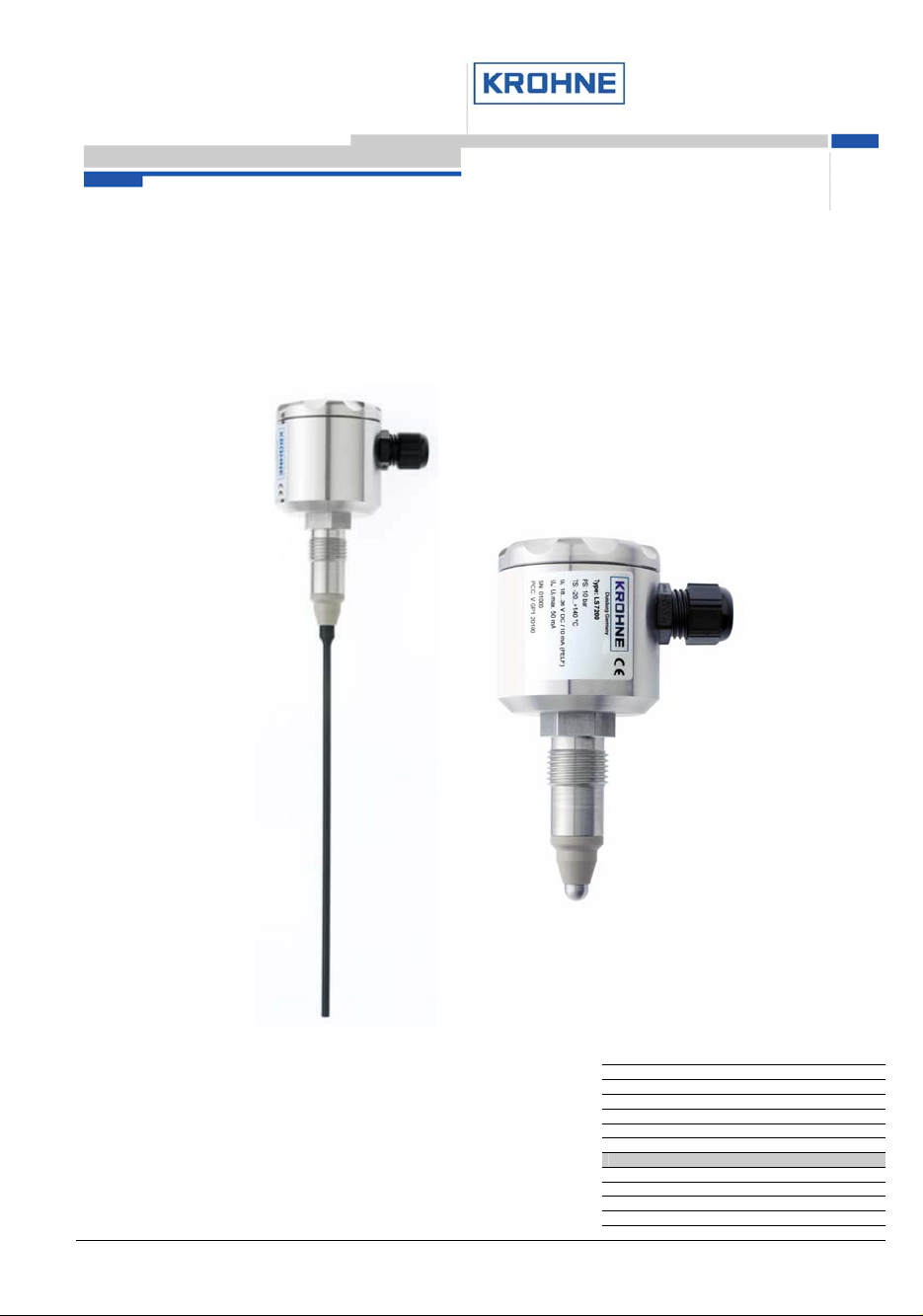
LS 72xx
Conductive mono-rod level sensor
Variable area flowmeters
Vortex flowmeters
Flow controllers
Electromagnetic flowmeters
Ultrasonic flowmeters
Mass flowmeters
Level measuring instruments
Communications engineering
Engineering systems and solutions
Switches, counters, displays and recorders
Heat metering
© KROHNE 02/2013 Pressure and temperature
Page 2

Contents
Items supplied .................................................................................................................................... 3
System description ............................................................................................................................ 3
Product liability and warranty ............................................................................................................. 3
CE / EMC / Standards / Approvals ..................................................................................................... 3
1 Installation ............................................................................................................................... 4
1.1 Mechanical installation .............................................................................................................. 4
1.2 Process connection ................................................................................................................... 4
1.3 Mounting of 3A marked products ............................................................................................... 5
2 Electrical connection .............................................................................................................. 6
2.1 Connection plan ........................................................................................................................ 7
2.2 Initial start-up ............................................................................................................................. 7
2.3 Operator control ........................................................................................................................ 7
3 Fault diagnosis and corrective actions ................................................................................. 7
4 Technical data ......................................................................................................................... 8
4.1 Technical data table .................................................................................................................. 8
4.2 Dimensions ............................................................................................................................... 9
5 Type code .............................................................................................................................. 10
5.1 Ordering code ......................................................................................................................... 10
5.2 Spare parts .............................................................................................................................. 10
5.3 Accessories ............................................................................................................................. 10
6 Product description .............................................................................................................. 11
6.1 Applications ............................................................................................................................. 11
6.2 Functional principle ................................................................................................................. 11
6.3 Construction ............................................................................................................................ 11
6.4 Features .................................................................................................................................. 11
7 Notes ...................................................................................................................................... 12
If you need to return a device for testing or repair to KROHNE ....................................................... 15
02/2013 LS 72xx 2
Page 3
Items supplied
6\VWHP_GHVFULSWLRQ_
• Measuring instrument
• Hygienic adapter
• Installation and operating instructions
System description
Inputting physical quantities into an SPC or PLC or other computer and control systems requires
accurate and reliably working sensors. The sensor is a detecting element that converts physical
quantities, such as temperature, level, pressure, conductivity, turbidity and flow, into an electrical
signal. Locally further processed, usually by an integrated microcontroller, the measuring signal can
be transmitted by analogue (e.g. 4...20mA loop) or digital (e.g. Profibus PA) means.
The conductive mono-rod-level sensors of the LS Series are designed to detect the level of
conductive liquids. Since the rod electrodes can be shortened to any required length, this allows
flexibility in the choice of the operating point.
Product liability and warranty
The instrument is designed solely for detecting the interface between conductive liquids.
Responsibility as to suitability and intended use of this instrument rests solely with the operator.
Improper installation and operation of the instrument / system may lead to loss of warranty.
In addition, all claims are subject to the “General terms and conditions of sale” under which this
instrument was purchased.
If a meter or instrument needs to be returned to KROHNE, please note the information given on the
last-but-one page of these Instructions.
KROHNE regrets that it cannot repair or check your instruments unless accompanied by a fully
completed Service and Repair sheet.
CE / EMC / Standards / Approvals
(applicable only with integrated electronic evaluator)
The product bears the CE marking on account of compliance with and application of the following
standards:
EMCG (89/336/EEC)
EN 50081-1 EN 55022 Class B
EN 61000-6-2 EN 61000-4-2 ESD 4/8 kV
EN 61000-4-3 RF radiated 10 V/m
EN 61000-4-4 Burst 4 kV
EN 61000-4-5 Surge 1 kV sym., 2 kV unsym.
EN 61000-4-6 RF cable 10 V
02/2013 LS 72xx 3
Page 4

1 Installation
1.1 Mechanical installation
• Use only the recommended sleeves or adapters. If other systems are used, no guarantee can
be given for proper functioning or leak-tightness.
• The connection thread must have direct electrical contact with the threaded sleeve and the
metal vessel.
• Do not use Teflon or paper gaskets.
• The stub electrode can be used in electrically non-conducting vessels (e.g. plastic tanks) if
the screw-in sleeve has a metal surface that can be used as reference ground.
• The tightening torque for the sleeve should be between 10 and
20 Nm.
• The rod electrodes can be shortened to any required length (by clipping, sawing, etc). Make
sure not to damage the coating or the insulating part.
• Insulated rods: remove about 10 mm of the coating from the end of the rod, using an abrasive
disc, a sanding belt or a sharp knife.
• Make absolutely sure that the rod electrode cannot come into contact with the pipe or tank
wall. Also take into consideration the fact that the rod may be deflected by movement in the
liquid product. If necessary, select a more favourable mounting location.
1.2 Process connection
The hygienic ½” process sleeve is easy to weld in into tanks or pipes. The kind of assembly allows
installation in conformity with standards of hygiene (to EHEDG, FDA). The G1/2” and G1”
connections can be mounted in any counter thread acc. to ISO 228.
Various hygienic adapter sleeves (refer to chapter “Accessories”) are available for fitting to other
process connections. For more information refer to data sheet “Accessories”
02/2013 LS 72xx 4
Page 5
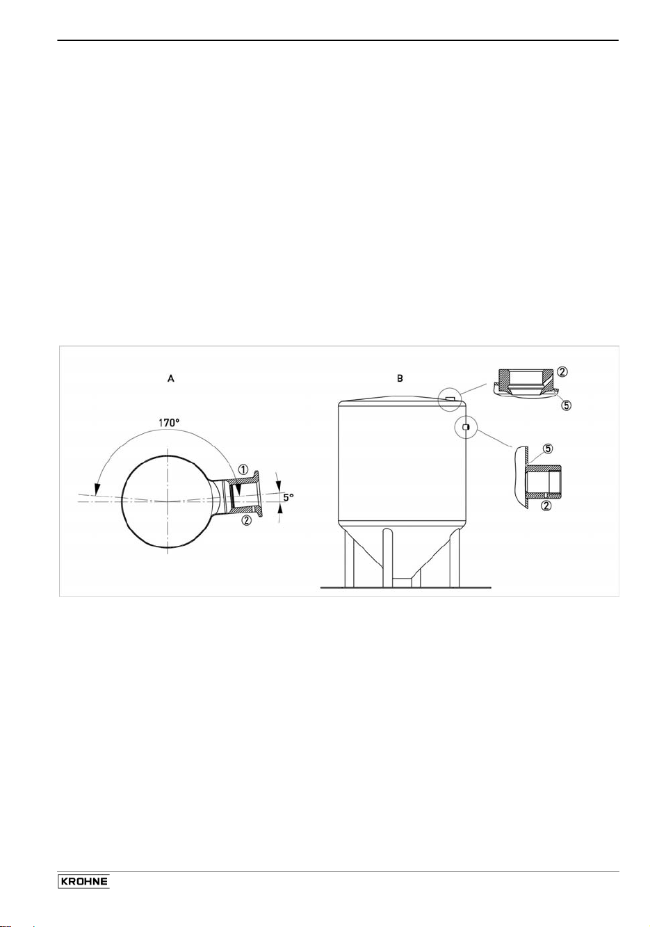
1.3 Mounting of 3A marked products
The 3A mark is valid only when the product is mounted in a 3A marked counterpart and installed acc.
to the installation manual. Use also a 3A marked O-ring or gasket if relevant.
The 3A marked products conforms to the 3A sanitary standards criteria. Materials and surfaces fulfil
the FDA demands and are certified by EHEDG.
EPDM O-rings supplied with 3A marked products are conform to sanitary standards class II (8% milk
fat).
1) Use only 3A approved counterparts
2) The inspection hole should be visible and drained. Face it downwards that leaking can be
observed.
3) Mount the device in a self-drained position.
4) Level the inner surface of the pipe with the counterpart.
5) Weld from the inside of the tank, if possible. Welds shall be free from cracks, crevices
and grooves. Weldings should be grinded to Ra= 0.8
Mounting of 3A products in pipe installations (A) or tank installations (B)
02/2013 LS 72xx 5
Page 6

2 Electrical connection
External level converter module
Terminal 1 is for the electrode potential, terminal 2 for ground (housing). Wire these two
connections to the appropriate terminals of your evaluation unit (see also “Accessories“). The pin
assignment for the M12 plug connection is shown in the connection diagram. Make absolutely
sure that the sensor has no DC voltage, as this could damage the sensor or tank! The most
suitable devices are evaluators with a frequency higher than 200 Hz. Do not use devices with an
r.m.s. voltage of more than 5 V. Also pay regard to currently valid installation regulations.
With integrated level converter module
Terminals 1 and 2 are used for supplying a DC voltage of 18...36 V. According to polarity, the
output switches to active or inactive when the electrode is immersed (see connection diagram).
The terminal wired to the negative pole is connected to the housing via an internal protective
diode. The maximum power consumption is 10 mA (without load switched). This value should be
taken into account for the recommended fuse. An active switching output (pnp) is available at
terminal 3. The switching voltage is a minimum of 1 V below the supply voltage. The maximum
output current is 50 mA. At higher loads, the current is limited accordingly. Damage through
shorting cannot occur. At terminal 4 (connection “R“) the sensitivity can be set in three stages,
either by fixed wiring or by external activation for changeover in the case of product changes (see
Table). The pin assignment for the M12 plug connection is shown in the connection diagram.
Please pay regard to the respectively valid installation regulations.
R Operating point Examples
L
open
L+
200 Ω
2 kΩ
20 kΩ
acids, alkalis
beer, juice, yoghurt
(pure) water Connection diagram
02/2013 LS 72xx 6
Page 7

2.1 Connection plan
2.2 Initial start-up
• Check the leak-tightness at the sleeve.
• Make sure that the cable gland is tight or, as the case may be, the M12 plug is properly
screwed down.
• After powering the unit, check for correct switching function.
2.3 Operator control
External level converter module
Refer to the directions for the appropriate evaluator and set the sensitivity level accordingly.
With integrated level converter module
• The red LED in the evaluator module lights up when the electrode is immersed in the liquid
product of adequate conductivity.
• According to the polarity of the supply voltage (see “Electrical connection“) the output
operates in the active or inactive mode.
• Should the module fail to switch, check the sensitivity setting (see “Electrical connection“).
3 Fault diagnosis and corrective actions
Fault Cause Action/elimination
No indication of level Electrode not in product o.k.
Measure continuity,
02/2013 LS 72xx 7
Page 8

Wire break
Sensitivity too low
Insufficient electrode area
Constant level indication Short-circuit to ground, sensor
Short-circuit
Sensitivity too high (possibly
deposits)
connections
Select higher sensitivity
Strip more insulation from
electrode
Replace sensor
Check power leads, power
cable
Select lower sensitivity
With integrated level converter module
LED not “on” Supply voltage < 18 V Measure voltage at pin 1, 2
No switching output Wire break
Supply polarity incorrect
Short-circuit
Check continuity of wires
Reverse terminals 1, 2
Check wiring
4 Technical data
4.1 Technical data table
Connection head Stainless steel V2A 1.4305; 55 mm dia.
Electrical connection Cable gland M16; M12 connector
Process connection Threaded socket G1/2“h; V4A 1.4571
Type of protection IP 67
Insulating part PEEK
Electrode 4 mm dia.; V4A 1.4571
(Option: PTFE coating)
Ambient temp. range –20...+60 °C
Process temp. range –20...+140 °C
Operating pressure max. 16 bar
Mounting position Rod electrode: above; stub electrode: any
With integrated level converter module
Indicating elements 1 LED red (level)
Power supply 18...36 V DC; 10 mA max. (no load switched)
Output min. Ub – 1 V, (50 mA max. short-circuit-proof)
Switching function full / empty polarity of supply power
Response time Damping 0.5 s
Sensitivity
With electrode output for level converter module
Output electrode connection, ground connection
200 Ω, 2 kΩ, 20 kΩ via control signal
02/2013 LS 72xx 8
Page 9

4.2 Dimensions
02/2013 LS 72xx 9
Page 10

5 Type code
5.1 Ordering code
Parts code VGP1 0 x y 000 z
x: Type
2 Stub, integr. level converter module
3 Rod bare, electrode/ground connection
4 Rod bare, integr. level converter module
5
6
y: Rod length
1 200 mm, bare
2 500 mm, bare
3 850 mm, bare
4 1000 mm, bare
5 200 mm, coated
6 500 mm, coated
7 850 mm, coated
8 1000 mm, coated
z: Electrical connection
2 Plug M12
1 Stub, electrode/ground connection
Rod coated, electrode/ground connection
Rod coated, integr. level converter module
0 Stub
1 Cable gland M16
5.2 Spare parts
Should a replaceable part of the probe be lost or damaged, replacements can be
ordered on the basis of the part number.
Designation Type
Housing lid KMD.008.055.100
Cable gland M16 KVV.M16.010.008
Connector insert M12 4-pin KVV.100.004.000
Integrated level converter module LKP.100
5.3 Accessories
Designation Type
Weld-in sleeve, HWN 200 V GP7 010000
Liquiphanten adapter thread G1", HGA 200 V GP7 050000
Sanitary pipe assembly kit DN 25, HMT 225 V GP7 0A0000
Sanitary pipe assembly kit DN 50, HMT 250 V GP7 0B0000
Varivent flange version N, HVF 250 V GP7 0C0000
Tri-Clamp flange DN 32/DN 40, 2"; HTC 250 V GP7 0D0000
External level converter module,2-channel, 24VDC, LEM 202 V GP0 100090
External level converter module,24VDC, 4-channel, LEM 204 V GP0 100080
External level converter module, 230 V, LEM 100 V GP0 100070
02/2013 LS 72xx 10
Page 11

6 Product description
6.1 Applications
The conductive mono-rod-level sensors of the LS Series are designed to detect the
level of conductive liquids. Since the rod electrodes can be shortened to any
required length, this allows flexibility in the choice of the operating point.
6.2 Functional principle
Conductive measuring sensors pick up the electrical resistance of the tank product
when the electrode is immersed in the product. This causes a small alternating
current to flow which is measured by the electronic unit in the converter module. The
wall of the vessel or pipe acts as reverse potential. The switching position is defined
by the length or mounting position of the sensor.
6.3 Construction
The weldable process sleeve is made of stainless steel and ensures installation in
keeping with hygiene requirements. Various level converter modules (see
Accessories) are available for evaluation purposes. The integrated evaluator module
in the connection head allows direct connection to an SPC or PLC via a short-circuitproof 24-V switching signal.
6.4 Features
• Sensor for hygienic installation, no elastomers
• Compact design
• Rod electrode can be shortened to any length
• Optimized flow geometry
• Precise, constant operating point
• Rejection of foam and deposits (coated electrode)
• Insensitive to vibration
• Materials in conformity with food standards
• Maintenance-free
• Installation in pipelines DN 25 and higher
• Direct connection to an SPC or PLC (with integrated electronics)
• Hygienic adapter sleeves for other process connections
02/2013 LS 72xx 11
Page 12

7 Notes
02/2013 LS 72xx 12
Page 13

02/2013 LS 72xx 13
Page 14

02/2013 LS 72xx 14
Page 15

If you need to return a device for testing or repair to KROHNE
Your instrument has been carefully manufactured and tested. If installed and operated in
accordance with these operating instructions, it will rarely present any problems. Should you
nevertheless need to return an instrument for servicing or repair, please pay strict attention to the
following points:
Due to statutory regulations on environmental protection and safeguarding the health and safety of
our personnel, KROHNE may only handle, test and repair returned instruments that have been in
contact with liquids if it is possible to do so without risk to personnel and environment.
This means that KROHNE can only service your instrument if accompanied by the following
certificate confirming that the instrument is safe to handle. If the instrument has been operated with
toxic, caustic, flammable or water-endangering liquids, you are kindly requested
to check and ensure, if necessary by rinsing or neutralising, that all cavities in the instrument are
free from such dangerous substances.
(Directions on how you can find out whether the primary head has to be opened and flushed out or
neutralised are obtainable from KROHNE on request.)
to attach a certificate to the instrument confirming that the instrument is safe to handle and stating
the liquid used.
We cannot service your instrument unless accompanied by such a certificate.
Specimen certificate
Company: Address:
Department: Name:
Tel. No.: Fax No.:
The enclosed instrument
Type: .:
KROHNE Order No. or Series No
has been operated with the following process liquid
Because this process liquid is
water-hazardous toxic caustic flammable
*
we have
checked that all cavities in the instrument are free from such substances *
flushed out and neutralised all cavities in the instrument *
We confirm that there is no risk to humans or environment through any residual liquid contained in
the instrument.
Date: Signature Signature:
Company stamp:
02/2013 LS 72xx 15
 Loading...