

Page 1
Handbook
Handbook
OPTISENS IND 1000
OPTISENS IND 1000
OPTISENS IND 1000OPTISENS IND 1000
HandbookHandbook
Inductive conductivity sensor
The documentation is only complete when used in combination with the relevant
documentation for the signal converter.
© KROHNE 12/2016 - 4001969202 - MA OPTISENS IND 1000 R02 en
Page 2

:
IMPRINT
:::::::::::::::::::::::::::::::::::::::
All rights reserved. It is prohibited to reproduce this documentation, or any part thereof, without
the prior written authorisation of KROHNE Messtechnik GmbH.
Subject to change without notice.
Copyright 2016 by
KROHNE Messtechnik GmbH - Ludwig-Krohne-Str. 5 - 47058 Duisburg (Germany)
2
www.krohne.com 12/2016 - 4001969202 - MA OPTISENS IND 1000 R02 en
Page 3

OPTISENS IND 1000
CONTENTS
1 Safety instructions 5
1.1 Intended use ..................................................................................................................... 5
1.2 Safety instructions from the manufacturer ..................................................................... 5
1.2.1 Copyright and data protection ................................................................................................ 5
1.2.2 Disclaimer ............................................................................................................................... 6
1.2.3 Product liability and warranty ................................................................................................ 6
1.2.4 Information concerning the documentation........................................................................... 6
1.2.5 Warnings and symbols used................................................................................................... 7
1.3 Safety instructions for the operator................................................................................. 7
2 Device description 8
2.1 Scope of delivery............................................................................................................... 8
2.2 Device description ............................................................................................................ 9
2.2.1 Sensor types............................................................................................................................ 9
2.3 Nameplate ...................................................................................................................... 11
3 Installation 12
3.1 General notes on installation ......................................................................................... 12
3.2 Storage and Transport ................................................................................................... 12
3.3 Installation procedure .................................................................................................... 12
3.4 Pre-installation requirements ....................................................................................... 13
3.5 Safety instructions.......................................................................................................... 14
3.5.1 Connecting the sensor cable to the signal converter MAC 100 ........................................... 14
3.6 Calibrating the sensor.................................................................................................... 15
3.7 Installing the sensor....................................................................................................... 16
3.7.1 General installation instructions.......................................................................................... 16
3.7.2 Mounting to a flow through assembly .................................................................................. 17
3.7.3 Mounting sensor with immersion assembly ........................................................................ 17
3.8 Examples of a typical measuring point.......................................................................... 18
4 Operation 19
4.1 Menu mode structure..................................................................................................... 19
4.2 Function tables ............................................................................................................... 20
4.2.1 Menu A, quick setup.............................................................................................................. 20
4.2.2 Menu B, test .......................................................................................................................... 20
4.2.3 Menu C, setup ....................................................................................................................... 21
4.3 Calibration ...................................................................................................................... 23
4.3.1 Temperature compensation .................................................................................................23
4.3.2 Calibrating the temperature measurement......................................................................... 25
4.3.3 Calibrating measurement..................................................................................................... 26
4.3.4 Calibration log....................................................................................................................... 30
4.4 Troubleshooting.............................................................................................................. 30
www.krohne.com12/2016 - 4001969202 - MA OPTISENS IND 1000 R02 en
3
Page 4

CONTENTS
OPTISENS IND 1000
5 Service 31
5.1 Maintenance ................................................................................................................... 31
5.1.1 Cleaning ................................................................................................................................ 31
5.2 Spare parts availability...................................................................................................31
5.3 Availability of services .................................................................................................... 31
5.4 Returning the device to the manufacturer..................................................................... 31
5.4.1 General information.............................................................................................................. 31
5.4.2 Form (for copying) to accompany a returned device............................................................ 32
5.5 Disposal .......................................................................................................................... 32
6 Technical data 33
6.1 Measuring principle........................................................................................................33
6.1.1 Inductive conductivity measurement.................................................................................... 33
6.2 Technical data................................................................................................................. 34
6.3 Dimensions ..................................................................................................................... 35
7 Notes 38
4
www.krohne.com 12/2016 - 4001969202 - MA OPTISENS IND 1000 R02 en
Page 5

OPTISENS IND 1000
1.1 Intended use
CAUTION!
Responsibility for the use of the measuring devices with regard to suitability, intended use and
corrosion resistance of the used materials against the measured fluid lies solely with the
operator.
INFORMATION!
The manufacturer is not liable for any damage resulting from improper use or use for other than
the intended purpose.
The intended use of OPTISENS IND 1000 conductivity sensor is the measurement of conductive
liquids. The sensor is suitable for connection to the MAC 100 signal converter.
1.2 Safety instructions from the manufacturer
1.2.1 Copyright and data protection
The contents of this document have been created with great care. Nevertheless, we provide no
guarantee that the contents are correct, complete or up-to-date.
SAFETY INSTRUCTIONS
1
The contents and works in this document are subject to copyright. Contributions from third
parties are identified as such. Reproduction, processing, dissemination and any type of use
beyond what is permitted under copyright requires written authorisation from the respective
author and/or the manufacturer.
The manufacturer tries always to observe the copyrights of others, and to draw on works created
in-house or works in the public domain.
The collection of personal data (such as names, street addresses or e-mail addresses) in the
manufacturer's documents is always on a voluntary basis whenever possible. Whenever
feasible, it is always possible to make use of the offerings and services without providing any
personal data.
We draw your attention to the fact that data transmission over the Internet (e.g. when
communicating by e-mail) may involve gaps in security. It is not possible to protect such data
completely against access by third parties.
We hereby expressly prohibit the use of the contact data published as part of our duty to publish
an imprint for the purpose of sending us any advertising or informational materials that we have
not expressly requested.
www.krohne.com12/2016 - 4001969202 - MA OPTISENS IND 1000 R02 en
5
Page 6

1
SAFETY INSTRUCTIONS
1.2.2 Disclaimer
The manufacturer will not be liable for any damage of any kind by using its product, including,
but not limited to direct, indirect or incidental and consequential damages.
This disclaimer does not apply in case the manufacturer has acted on purpose or with gross
negligence. In the event any applicable law does not allow such limitations on implied warranties
or the exclusion of limitation of certain damages, you may, if such law applies to you, not be
subject to some or all of the above disclaimer, exclusions or limitations.
Any product purchased from the manufacturer is warranted in accordance with the relevant
product documentation and our Terms and Conditions of Sale.
The manufacturer reserves the right to alter the content of its documents, including this
disclaimer in any way, at any time, for any reason, without prior notification, and will not be liable
in any way for possible consequences of such changes.
1.2.3 Product liability and warranty
The operator shall bear responsibility for the suitability of the device for the specific purpose.
The manufacturer accepts no liability for the consequences of misuse by the operator. Improper
installation or operation of the devices (systems) will cause the warranty to be void. The
respective "Standard Terms and Conditions" which form the basis for the sales contract shall
also apply.
OPTISENS IND 1000
1.2.4 Information concerning the documentation
To prevent any injury to the user or damage to the device it is essential that you read the
information in this document and observe applicable national standards, safety requirements
and accident prevention regulations.
If this document is not in your native language and if you have any problems understanding the
text, we advise you to contact your local office for assistance. The manufacturer can not accept
responsibility for any damage or injury caused by misunderstanding of the information in this
document.
This document is provided to help you establish operating conditions, which will permit safe and
efficient use of this device. Special considerations and precautions are also described in the
document, which appear in the form of icons as shown below.
6
www.krohne.com 12/2016 - 4001969202 - MA OPTISENS IND 1000 R02 en
Page 7
OPTISENS IND 1000
1.2.5 Warnings and symbols used
Safety warnings are indicated by the following symbols.
DANGER!
This warning refers to the immediate danger when working with electricity.
DANGER!
This warning refers to the immediate danger of burns caused by heat or hot surfaces.
DANGER!
This warning refers to the immediate danger when using this device in a hazardous atmosphere.
DANGER!
These warnings must be observed without fail. Even partial disregard of this warning can lead to
serious health problems and even death. There is also the risk of seriously damaging the device
or parts of the operator's plant.
SAFETY INSTRUCTIONS
1
WARNING!
Disregarding this safety warning, even if only in part, poses the risk of serious health problems.
There is also the risk of damaging the device or parts of the operator's plant.
CAUTION!
Disregarding these instructions can result in damage to the device or to parts of the operator's
plant.
INFORMATION!
These instructions contain important information for the handling of the device.
LEGAL NOTICE!
This note contains information on statutory directives and standards.
• HANDLING
HANDLING
HANDLINGHANDLING
This symbol designates all instructions for actions to be carried out by the operator in the
specified sequence.
i RESULT
RESULT
RESULTRESULT
This symbol refers to all important consequences of the previous actions.
1.3 Safety instructions for the operator
WARNING!
In general, devices from the manufacturer may only be installed, commissioned, operated and
maintained by properly trained and authorized personnel.
This document is provided to help you establish operating conditions, which will permit safe and
efficient use of this device.
www.krohne.com12/2016 - 4001969202 - MA OPTISENS IND 1000 R02 en
7
Page 8
2
DEVICE DESCRIPTION
2.1 Scope of delivery
INFORMATION!
Inspect the packaging carefully for damages or signs of rough handling. Report damage to the
carrier and to the local office of the manufacturer.
INFORMATION!
Do a check of the packing list to make sure that you have all the elements given in the order.
INFORMATION!
Look at the device nameplate to ensure that the device is delivered according to your order.
Check for the correct supply voltage printed on the nameplate.
OPTISENS IND 1000
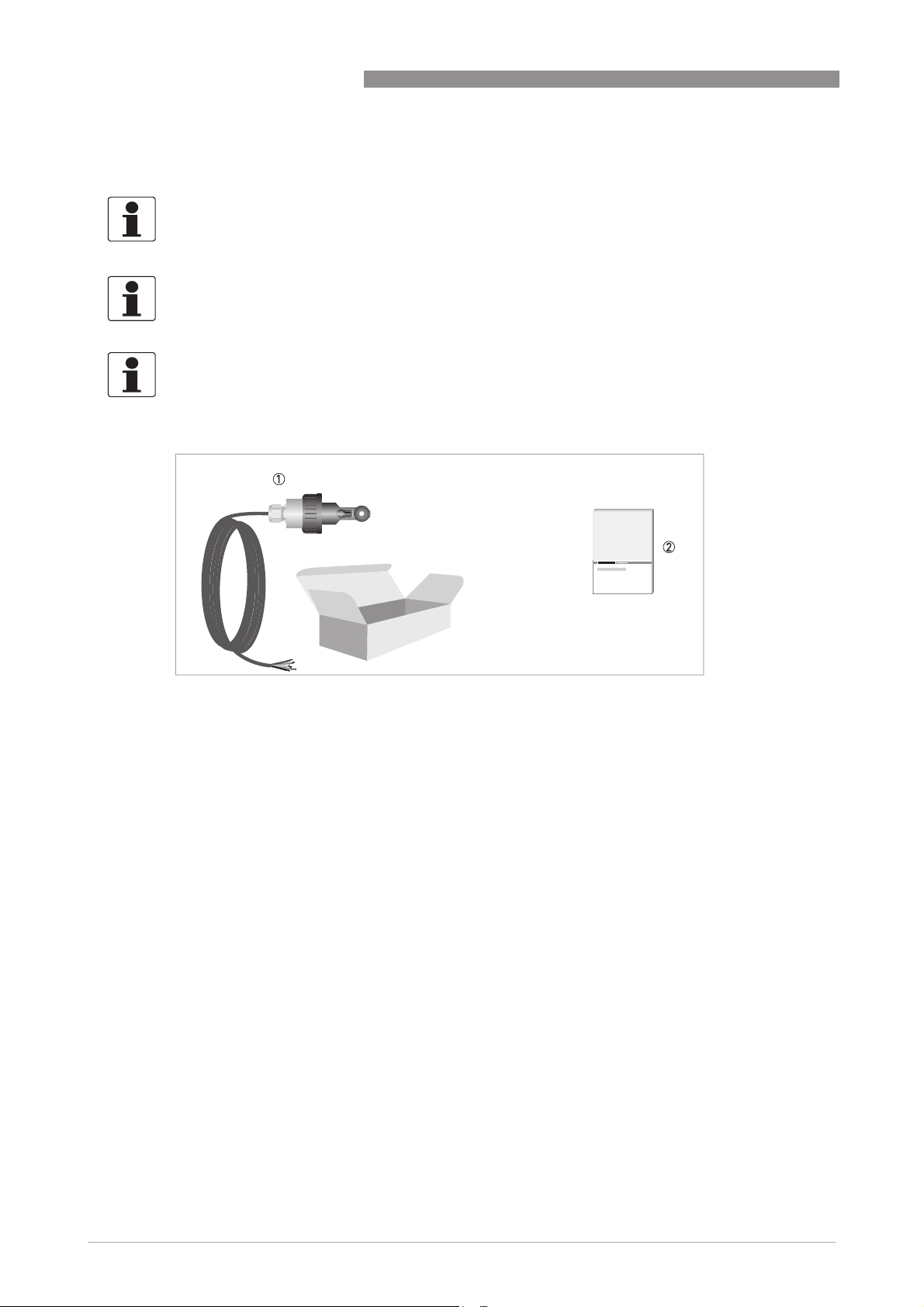
Figure 2-1: Standard scope of delivery
1 Ordered sensor with fixed cable 10 m / 33 ft
2 Documentation
Optional accessories
• SENSOFIT FLOW 1000 flow-through assembly (T-piece)
8
www.krohne.com 12/2016 - 4001969202 - MA OPTISENS IND 1000 R02 en
Page 9
OPTISENS IND 1000
2.2 Device description
2.2.1 Sensor types
DEVICE DESCRIPTION
2
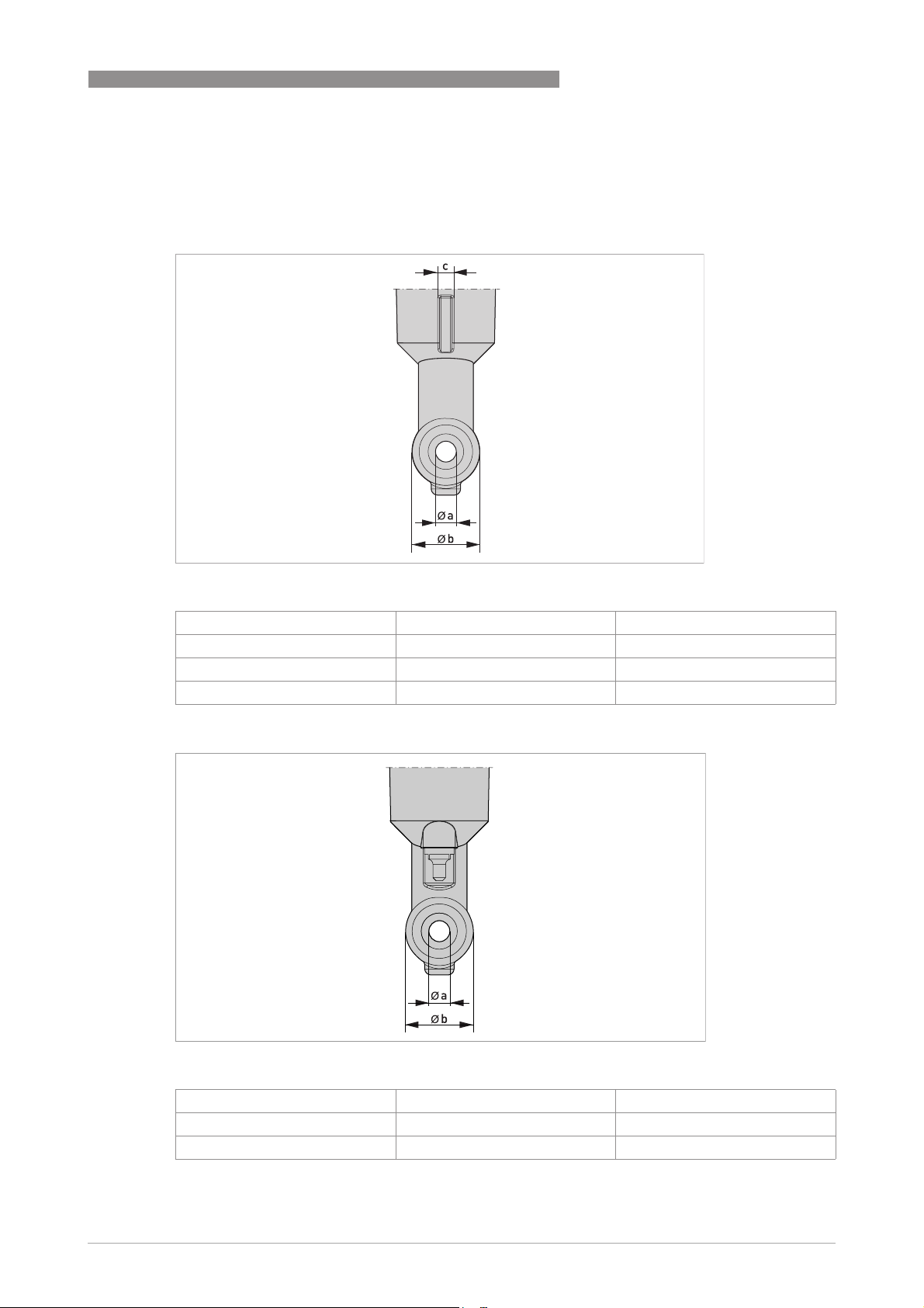
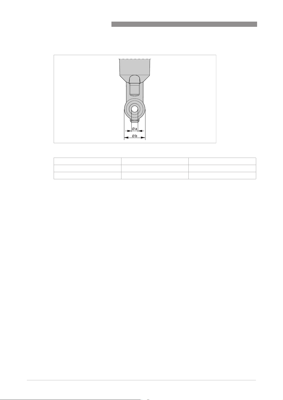
Figure 2-2: Sensor rear view with guide slot
Dimension [mm] Dimension [inch]
a 6.7 0.26
b 22 0.87
c 4 0.16
Figure 2-3: Sensor front view with exposed temperature sensor (standard sensor)
Dimension [mm] Dimension [inch]
a 6.7 0.26
b 22 0.87
www.krohne.com12/2016 - 4001969202 - MA OPTISENS IND 1000 R02 en
9
Page 10
2
DEVICE DESCRIPTION
Figure 2-4: Sensor front view with internal temperature sensor
a 6.7 0.26
b 22 0.87
OPTISENS IND 1000
Dimension [mm] Dimension [inch]
The OPTISENS IND 1000 sensor features a compact and extremely rugged design as well as a
wide measuring range. The meaurement coils are completely enclosed and there is no direct
contact of the measurement coils to the medium. This feature makes it corrosion resistant and
suitable for measurement mediums with a high dirt load.
The body is either out of PP or PVDF. The sensor features an exposed or internal Pt1000
temperature sensor which reading is used for the temperature compensation of the conductivity.
Combined with a signal converter, an extremely reliable and cost-effective measuring systems
can be created. Inductive measurement systems are very well suited for conductivity
measurements in severely contaminated and aggressive media in all industries.
10
www.krohne.com 12/2016 - 4001969202 - MA OPTISENS IND 1000 R02 en
Page 11
OPTISENS IND 1000
Thanks to its compact design, the sensor can be installed in pipelines with relatively small
diameters. The immersion depth from screw fitting to sensor tip is just 81 mm and such suitable
for DN50 pipes. The measurement field requires a minimum of 20 mm free space around the
sensor coils to not have an impact onto the cell factor.
DEVICE DESCRIPTION
2
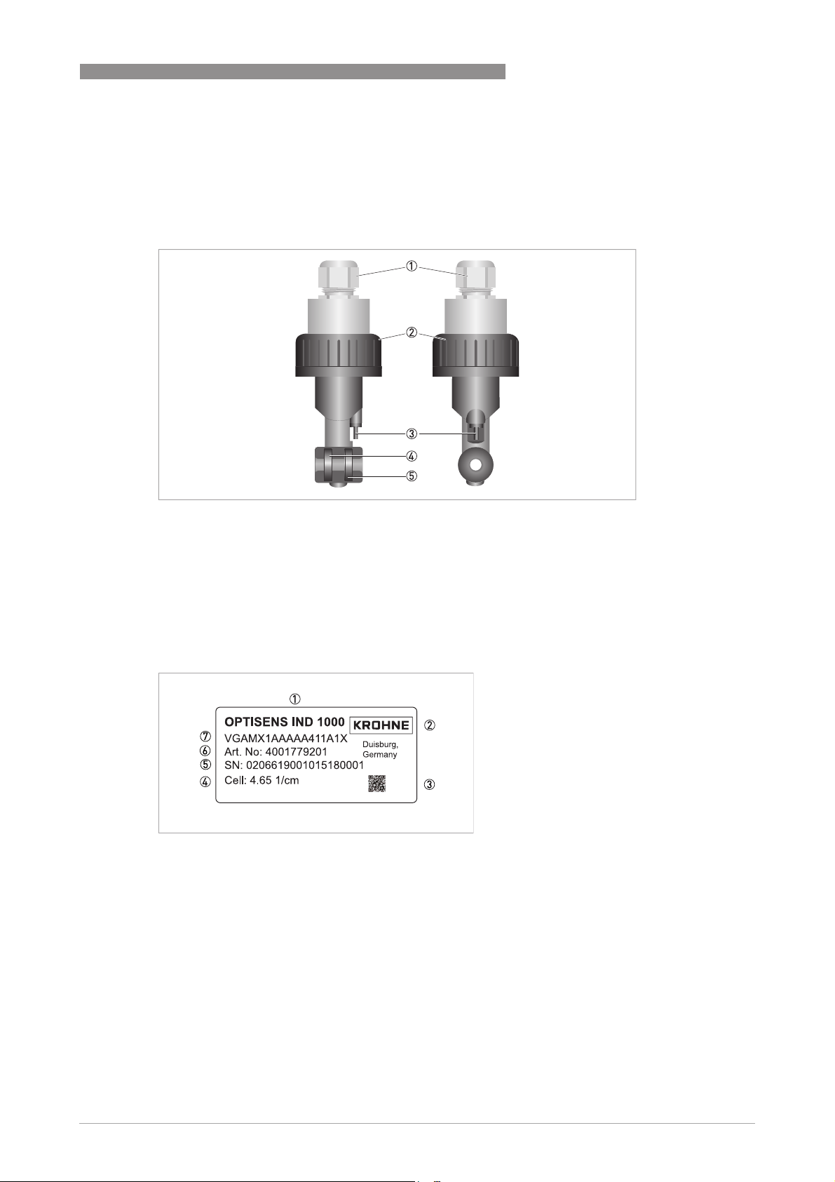
Figure 2-5: Sensor overview
1 Cable gland
2 Union nut PVC (optional stainless steel)
3 Exposed temperature sensor Pt1000
4 Primary coil
5 Secondary coil
2.3 Nameplate
Figure 2-6: Example of a nameplate
1 Device name
2 Manufacturer
3 Matrix code of the serial number
4 Cell factor
5 Serial number
6 Articel number
7 Order code
www.krohne.com12/2016 - 4001969202 - MA OPTISENS IND 1000 R02 en
11
Page 12

3
INSTALLATION
3.1 General notes on installation
INFORMATION!
Inspect the packaging carefully for damages or signs of rough handling. Report damage to the
carrier and to the local office of the manufacturer.
INFORMATION!
Do a check of the packing list to make sure that you have all the elements given in the order.
INFORMATION!
Look at the device nameplate to ensure that the device is delivered according to your order.
Check for the correct supply voltage printed on the nameplate.
3.2 Storage and Transport
• Store the conductivity measuring system in its original packaging in a dry and dust-free
location. Keep it away from dirt.
• The original packaging serves the protection of the equipment. Therefore always use it for
transport or return to the manufacturer.
OPTISENS IND 1000
3.3 Installation procedure
Most new inductive sensors get installed not needing a further calibration and adjustment of the
cell factor. However, it is good practice to calibrate a sensor at time of installation into its final
measuring location. The cell factor might vary ±15%. Follow the installation order:
1. Unpack the sensor.
2. Connect the sensor to the signal converter.
3. Program the cell factor of the inductive sensor used (PP version c=6.25, PVDF version c=4.65)
4. Adjust the cell factor against a known value after the following step or calibrate the sensor in
a standard solution (e.g. 25 mS/cm). Make sure the coils are minimum 20 mm away from any
surface and fully immersed in the solution.
5. Install the sensor into its final measuring location.
The required steps are explained in the following sections.
12
www.krohne.com 12/2016 - 4001969202 - MA OPTISENS IND 1000 R02 en
Page 13

OPTISENS IND 1000
3.4 Pre-installation requirements
CAUTION!
•
Unpack the sensor carefully!
•
Make sure that the sensor is clean.
INFORMATION!
•
Nothing shall block the measurement hole within the sensor.
•
Consider a large enough distance from metal or plastic pipe walls!
The sensor can be installed into the SENSOFIT FLOW 1000 assembly which is available in DN32,
DN40 and DN50.
If installed into small diameter pipes like DN32 and DN40 the minimal free diameter of 20 mm
around the sensor coils can not be kept. In these cases the cell factor has to be adjusted. The
best method is to do an inline calibration against a reference measurement. In case this is not
possible try to achive similar dimensions and materials in a calibration beaker. In case both is
not possible you can adjust the cell factor by multiplying it by a factor. Every sensor coil is
different or might vary in its characteristics. A multiplier can only be given as an approximate
indication. Within a SENSOFIT FLOW 1000 with DN32 you do have ~8mm and with DN 40 ~14mm
free space around the sensor available, both being less then 20mm. Mentioned multipliers are
approximates only. Therefore the recommendation is to install in a pipe equal or bigger then
DN50.
INSTALLATION
3
Multipliers for cell factor correction depending on pipe dimensions
SENSOFIT FLOW 1000 Free space around the sensor coil Approximate multiplier for cell
DN32 ~8 mm ~1.09 (non conductive pipe)
DN40 ~14 mm ~1.05 (non conductive pipe)
DN50 ~21 mm ~1.00
factor correction
~0.97 (conductive pipe).
~0.98 (conductive pipe).
www.krohne.com12/2016 - 4001969202 - MA OPTISENS IND 1000 R02 en
13
Page 14
3
INSTALLATION
3.5 Safety instructions
DANGER!
For devices used in hazardous areas, additional safety notes apply; please refer to the Ex
documentation.
DANGER!
All work on the electrical connections may only be carried out with the power disconnected.
DANGER!
Observe the national regulations for electrical installations!
WARNING!
Observe without fail the local occupational health and safety regulations. Any work done on the
electrical components of the measuring device may only be carried out by properly trained
specialists.
OPTISENS IND 1000
INFORMATION!
Look at the device nameplate to ensure that the device is delivered according to your order.
3.5.1 Connecting the sensor cable to the signal converter MAC 100
DANGER!
All work on the electrical connections may only be carried out with the power disconnected. Take
note of the voltage data on the nameplate!
INFORMATION!
Look at the device nameplate to ensure that the device is delivered according to your order.
Check for the correct supply voltage printed on the nameplate.
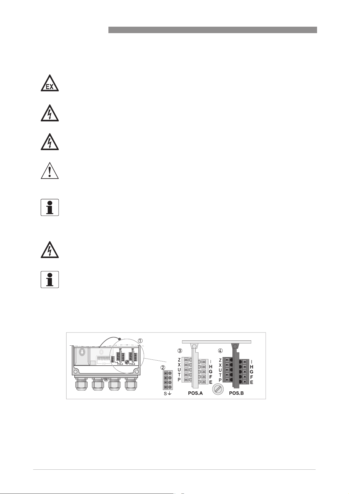
When ordering the single channel version, only the interface "Pos.A" is populated. In the version
with dual channels the interfaces "Pos.A" and "Pos.B" are populated.
14
Figure 3-1: Terminal compartment overview
1 Sensor connection terminals
2 Terminal block S (protective earth)
3 Terminal block A : terminal for sensor
www.krohne.com 12/2016 - 4001969202 - MA OPTISENS IND 1000 R02 en
Page 15

OPTISENS IND 1000
Figure 3-2: Connection of the sensor cable
The following instructions describe the connection of the sensor cable
Connecting the sensor cable to the signal converter
• Thread the sensor cable through the middle right cable gland (1).
• Push the wire (9) into the terminal block Pos A as described in the chart.
• To remove a cable, press down the white clip (10) on the corresponding terminal and pull the
cable out.
INSTALLATION
3
Wire Terminal block A or B
Shield (2) S
Yellow - Pt1000 (3) X
Green - Pt1000 (4) P
Shield from pink (5) H
Pink (6) G
White (7) F
Brown (8) E
3.6 Calibrating the sensor
It is good practice to calibrate an inductive sensor before installation. For further information
refer to
Calibrating measurement
on page 26. Then continue with the installation procedure.
www.krohne.com12/2016 - 4001969202 - MA OPTISENS IND 1000 R02 en
15
Page 16

3
INSTALLATION
3.7 Installing the sensor
3.7.1 General installation instructions
WARNING!
Ensure that the pipe is without pressure before installing or removing a sensor!
INFORMATION!
Be sure that the tube is completely filled with water, otherwise the measuring reading is wrong.
INFORMATION!
During installation you should fix a shut-off valve in front of and behind the instrument so that
the sensor can be taken out of the bypass in case of check.
INFORMATION!
To achieve reliable measuring results, note the following items:
•
Always install the sensor in the designated flow through assembly or ensure that the pipe
diameter is large enough.
•
The sensor must always have full contact with the measuring medium.
OPTISENS IND 1000
16
Figure 3-3: Installation requirements
1 Flow direction
www.krohne.com 12/2016 - 4001969202 - MA OPTISENS IND 1000 R02 en
Page 17

OPTISENS IND 1000
3.7.2 Mounting to a flow through assembly
WARNING!
Ensure that the pipe is without pressure before installing or removing a sensor!
INFORMATION!
The flow through assembly is an optional accessory and not part of the standard scope of
delivery. It has to be installed vertically to the flow direction.
INSTALLATION
3
Figure 3-4: Mounting to a flow-through assembly
1 Sensor
2 Flow-through assembly (T-piece)
• Screw the sensor 1 into the flow through assembly 2 and tighten the sensor by hand.
3.7.3 Mounting sensor with immersion assembly
Figure 3-5: Sensor in immersion version
1 Sensor with attached cable
2 Immersion assembly
3 Clamps onto immersion assembly
4 Cap with cable gland
The Sensor is also available as immersion version with 1000 or 2000 mm length. The sensor is
already installed and sealed inside the assembly. The assembly is equipped with retaining
clamps.
www.krohne.com12/2016 - 4001969202 - MA OPTISENS IND 1000 R02 en
17
Page 18

3
INSTALLATION
3.8 Examples of a typical measuring point
The following examples each show the signal converter, a sensor with integrated temperature
sensor, and the flow-through or immersion assembly.
Figure 3-6: Bypass installation with signal converter
1 Bypass measurement
2 Outlet measurement
3 Shut-off valve
4 Flow-through assembly (T-piece) with sensor
5 Bypass pipe
6 Main pipe
OPTISENS IND 1000
18
Figure 3-7: Installation with signal converter
1 Single channel version
www.krohne.com 12/2016 - 4001969202 - MA OPTISENS IND 1000 R02 en
Page 19

OPTISENS IND 1000
4.1 Menu mode structure
INFORMATION!
The following table just presents an overview. When programming the device, always consult the
function tables additionally as they contain further information!
Only the sensor relevant menus are shown in the following tables. For detailed information
about the general setting refer to the MAC 100 signal converter manual.
OPERATION
4
Measurnig
mode
3 or 4
pages,
scrolling
with ↓ or ↑
Main menu Submenu Parameter
>2.5s^A quick
A quick
A quick A quick
setup
setup
setupsetup
B test
B test B1 sim. process
B testB test
C setup
C setup C1 process input A C1.1 parameter
C setupC setup
↓↑ ↓↑ ↓↑
>^A6 analog outputs A6.1 measurement >^For
A6.2 spec. conductivity
A6.3 range
A6.4 time constant
input A
B4 actual values B4.2 process input A
B6 information B6.2 process input A
B1.1 temperature
B1.2 spec. conductivity
B1.3 spec. resistance
B4.2.1 temperature
B4.2.2 spec. conductivity
B4.2.3 Meg. Ohm
B4.2.5 pH
B4.2.8 generator volt.
B4.2.9 CPU temp.
B4.2.10 range
B4.2.11 electrode volt.
C1.2 cell constant
C1.14 time constant
C1.15 temperature
C1.23 cell calibration
further
informatio
n see
function
tables.
www.krohne.com12/2016 - 4001969202 - MA OPTISENS IND 1000 R02 en
19
Page 20

4
OPERATION
4.2 Function tables
To enter the menu from the measurement display point press > for more than 2.5 seconds, then
release the button. You are in the main menu level. Press up and down until the relevant menu
point is highlighted. Enter the menu point by pressing >
4.2.1 Menu A, quick setup
INFORMATION!
Note that the appearance of some sub-menus depends on the hardware setting and the used
sensor(s). Also only the sensor relevant menus and submenus are shown here in detail. For all
other menu functions refer to the MAC 100 signal converter manual.
A 6.1 measurement:
A 6.1 measurement:
A 6.1 measurement: A 6.1 measurement:
Value used for driving the current output C. Choose between:
• spec. conductivity
• temperature
• concentration % (function is choosable, but not implemented)
OPTISENS IND 1000
A 6.2 spec. conductivity
A 6.2 spec. conductivity
A 6.2 spec. conductivityA 6.2 spec. conductivity
Unit for the current output range. Choose between:
• µS/cm
• mS/cm
• free unit
4.2.2 Menu B, test
INFORMATION!
Note that the appearance of some sub-menus depends on the hardware setting and the used
sensor(s). Also only the sensor relevant menus and sub-menus are shown here in detail. For all
other menu functions refer to the MAC 100 signal converter manual.
The procedure to start the simulation process is the same for all functions:
• Choose the function with the help of ↓ or ↑ and press ^.
i You see the two options "set value" (opens the editor to enter the simulation value) and
"break" (exits the menu without simulation).
• Choose the desired option with the help of ↑ or ↓ and press ^.
i If you chose "set value", the device asks "start simulation" and offers the options "no" (exits
the menu without simulation) or "yes" (starts the simulation finally).
• Choose the desired option with the help of ↑ or ↓ and press ^.
i If you chose "yes", the simulation starts.
20
www.krohne.com 12/2016 - 4001969202 - MA OPTISENS IND 1000 R02 en
Page 21

OPTISENS IND 1000
OPERATION
B1,sim.process inp.A
B2,sim.process inp.B
Level Designation / function Settings / descriptions
B1.1
B1.1 temperature In this menu the temperature can be simulated.
B1.1B1.1
B1.2
B1.2 spec. conductivitiy In this menu the conductivity can be simulated.
B1.2B1.2
B1.3
B1.3 spec. resistance In this menu the resistance can be simulated.
B1.3B1.3
B4, actual values
Level Designation / function Settings / descriptions
This menu groups several functions which allow to display the corresponding actual reading. The shown measurements
are depending on the device configuration.
B4.2
B4.2 process input A In this menu the measurements from process input A can be read.
B4.2B4.2
B4.3
B4.3 process input B In this menu the measurements from process input B can be read.
B4.3B4.3
For 2 channel version only.
B6, information
4
Level Designation / function Settings / descriptions
This menu groups several other menus which contain device specific information. The build-up of the display is the
same for all menus:
B6.1
B6.1 C number Identifies the types of electronics, is also located on the converter
B6.1B6.1
B6.2
B6.2 process input A Gives information about the electronical part of process input A.
B6.2B6.2
B6.3
B6.3 process input B Gives information about the electronical part of process input B.
B6.3B6.3
B6.4
B6.4 SW.REV.MS Gives information about the main software of the electronics.
B6.4B6.4
B6.5
B6.5 SW.REV.VIS Gives information about the user interface of the device.
B6.5B6.5
B6.6
B6.6 Electronic Revision ER Reference identification number, electronic revision and production date of
B6.6B6.6
nameplate.
For 2 channel version only.
the device; includes all hardware and software changes.
4.2.3 Menu C, setup
INFORMATION!
The signal converter MAC 100 has a dual process input, A and B. Each process input has an own
submenu in this main menu. Process input A is always present, i.e. there is always a board in the
interface "Pos.A" in the connection area. The interface of process input B only has a board with
the dual channel signal converter. Be aware that the definition which kind of measurement a
process input can do is defined when ordering the device. The configuration cannot be changed
later.
INFORMATION!
Note that the appearance of some submenus depends on the hardware setting and the used
sensor(s).
www.krohne.com12/2016 - 4001969202 - MA OPTISENS IND 1000 R02 en
21
Page 22

4
OPERATION
C1, process input A
C1, process input A
C1, process input AC1, process input A
C2, process input B
C2, process input B
C2, process input BC2, process input B
OPTISENS IND 1000
Level Designation / function Settings / descriptions
Process input A and B can be either a sensor 1 or a sensor 2. Further information about the type of sensor 1 or 2 please
refer to the signal converter manual "Sensor input combinations". Process input A is always present, process Input B
can be present.
Note: The exchange of a sensors 1 with a sensor 2, or vice versa, can only be done by the manufacturer!
Depending on the sensor which is connected to a slot A or B the menu changes.
C1.1
C1.1 parameter (cond. ind.) This menu item is for selecting the probe which is connected to process
C1.1C1.1
C1.2
C1.2 cell constant Enter cell constant.
C1.2C1.2
C1.14
C1.14 time constant Enter time constant.
C1.14C1.14
C1.15
C1.15 temperature Menu for temperature measurement. Available for sensor 1 and sensor 2.
C1.15C1.15
C1.15.1 probe Options:
C1.15.2 manual Only available if C1.15.1 is set to "manual".
C1.15.3 correction Offset correction for temperature measurement. Not available if C1.15.1 is
C1.15.4 limitation Measuring ranges for temperature measurement.
C1.15.5 temp. comp. Menu for activating the temperature compensation parameters for the
C1.15.6 temp. coefficient If you have chosen “linear” enter the temperature coefficient.
C1.15.7 ref. temperature If you have chosen “linear” enter the reference temperature.
C1.23
C1.23 cell calibration For detailed information refer to Calibration refer to
C1.23C1.23
C1.23.1 temp. comp. Menu for temperature measurement.
C1.23.2 temperature Menu for setup of manual temperature (manual temperature
C1.23.3 temp. coefficient Menu for setup of temperature coefficient (manual temperature
C1.23.4 spec. conductivity Enter the conductivity of the calibration fluid.
C1.23.5 cell constant Enter cell constant.
input A/B. The entries of this selection depends on the chosen device
configuration. The device configuration is customer specific and set during
production.
•
manual: used if no internal or external temperature sensor is connected to
the signal converter
•
Pt1000: used if an external Pt1000 temperature sensor is connected to the
signal converter
set to "manual". If you have chosen “Pt 1000” enter the temperature
correction.
measurement.
Options:
•
Linear: linear temperature compensation.
•
Off: temperature compensation is disabled.
Calibrating
measurement
Options:
•
off: temperature measurement is disabled.
•
manual: temperature value has to be entered manually.
•
automatic: temperature measurement is performed as configured
measurement).
measurement).
Menu for preparation of measurement:
•
Put probe into calibration fluid
•
Wait until measurement is stable.
•
Press enter to proceed.
Wait until concentration is measured.
Check slope, press enter, decide whether to store or to discard calibration
parameter.
on page 26
22
www.krohne.com 12/2016 - 4001969202 - MA OPTISENS IND 1000 R02 en
Page 23

OPTISENS IND 1000
CAUTION!
If you choose for measurement the temperature compensation "linear" than choose between
"automatic" or "manual" for the temperature compensation during calibration. If you choose for
measurement the temperature compensation "off" than choose also "off" for the temperature
compensation during calibration.
4.3 Calibration
4.3.1 Temperature compensation
There are three basic options for temperature compensation within the submenu probe in the
cell calibration menu:
• automatic:
automatic: the signal converter will automatically compensate temperature influences using
automatic:automatic:
the information of a Pt1000 temperature sensor.
• manual:
manual: the signal converter will compensate temperature influences using a manually
manual:manual:
entered value; this option only makes sense if the temperature of the measured medium is
quite constant.
• off:
off: temperature compensation is disabled.
off:off:
OPERATION
4
INFORMATION!
If you choose no compensation, the measured conductivity will most likely deviate from the
actual conductivity. The reason is that the conductivity of a specific medium varies depending on
the temperature of the medium.
The menu for temperature within the menu process input (A or B) offers the following options:
• Pt1000
Pt1000: choose this option if there is an external Pt1000 temperature sensor connected to the
Pt1000Pt1000
signal converter.
• manual
manual: choose this option if there is no internal or external temperature sensor connected
manualmanual
to the signal converter.
After starting-up the signal converter, the measuring screen appears. This is the standard
screen which is displayed automatically in the normal operating mode. If you are in this mode
and you want to choose the temperature compensation, you have to perform the following step:
www.krohne.com12/2016 - 4001969202 - MA OPTISENS IND 1000 R02 en
23
Page 24

4
OPERATION
Step 1: choosing the temperature compensation for the measurement
•
Press >>>> for more than 2.5 seconds, then release the button. You are on the main menu level. In the
upper line of the display "A" appears, beneath the main menu quick setup
•
Press or until the main menu setup
OPTISENS IND 1000
quick setup is highlighted.
quick setupquick setup
setup is highlighted.
setupsetup
MAIN MENU
A quick setup
B test
> C setup
> C setup
> C setup> C setup
D service
•
Press >>>> to enter the chosen menu.
You are on the first submenu level. In the upper line of the display "setup" and "c1" appears,
beneath the submenu process input A
•
Press or to select process input A
•
Press >>>> to enter the chosen menu.
You are on the second submenu level. In the upper line of the display "process input A"
and "c1.1"appears beneath the submenu parameter
•
Press or to select temperature
•
Press >>>> to enter the chosen menu.
You are on the third submenu level. In the upper line of the display "temperature"
and "C1.15.1" appears, beneath the submenu probe
•
Press or to select temp. comp.
•
Press >>>> to enter the chosen menu.
process input A is highlighted.
process input Aprocess input A
process input A.
process input Aprocess input A
parameter is highlighted.
parameterparameter
temperature
temperaturetemperature
temp. comp.
temp. comp.temp. comp.
probe is highlighted
probeprobe
• Now you can set up the temperature compensation. Press or to select off
off or linear
offoff
^ to confirm the entered value.
linear. Press
linearlinear
24
www.krohne.com 12/2016 - 4001969202 - MA OPTISENS IND 1000 R02 en
Page 25

OPTISENS IND 1000
4.3.2 Calibrating the temperature measurement
This section is only required if the measured temperature is not correct.
The temperature is commonly measured with the integrated temperature probe and therefore
step 2a does apply in most cases. In rare cases of a process being very stable in temperature
manual compensation is used and step 2b applies.
Step 2: correcting the temperature measurement
OPERATION
4
Step 2a: probe Pt1000
Read the currently measured temperature of the Pt1000 temperature sensor from the measurement
screen and write it down.
Measure the temperature with a reference thermometer and check if it deviates from the temperature
measured by the Pt1000.
•
•
probe Pt1000
probe Pt1000probe Pt1000
Press >>>> for more than 2.5 seconds, then release the button. You are on the main menu level. In the
upper line of the display "A" appears, beneath the main menu setup
Press or until the main menu setup
MAIN MENU
A quick setup
B test
> C setup
> C setup
> C setup> C setup
D service
•
Press >>>> to enter the chosen menu.
You are on the first submenu level. In the upper line of the display "setup" and "c1" appears,
beneath the submenu process input A
pH is configurated.
•
Press or to select process input A
•
Press >>>> to enter the chosen menu .
You are on the second submenu level. Press or until the submenu temperature
highlighted.
•
Press >>>> to enter the chosen menu.
You are on the third submenu level. Press or until the submenu correction
highlighted.
•
Press >>>> to enter the chosen menu.
•
Press or and to change the reading.
•
Press ^ to confirm the value
setup is highlighted.
setupsetup
process input A is highlighted. Choose process input A or B where ever
process input Aprocess input A
process input A.
process input Aprocess input A
setup is highlighted.
setupsetup
temperature is
temperaturetemperature
correction is
correctioncorrection
• If necessary, enter the temperature correction in Kelvin so that the signal converter shows the
same temperature as the reference thermometer. Press ^ to confirm the entered value. The
temperature sensor has been adjusted.
www.krohne.com12/2016 - 4001969202 - MA OPTISENS IND 1000 R02 en
25
Page 26

4
OPERATION
OPTISENS IND 1000
Step 2b: probe manual
Measure the temperature of the measuring medium.
•
•
probe manual
probe manualprobe manual
Press >>>> for more than 2.5 seconds, then release the button. You are on the main menu level. In the
upper line of the display "A" appears, beneath the main menu setup
Press or until the main menu setup
MAIN MENU
A quick setup
B test
> C setup
> C setup
> C setup> C setup
D service
•
Press >>>> to enter the chosen menu.
You are on the first submenu level. In the upper line of the display "setup" and "c1" appears,
beneath the submenu process input A
•
Press or to select process input A
•
Press >>>> to enter the chosen menu process input A
You are on the second submenu level. Press or until the submenu temperature
highlighted.
•
Press >>>> to enter the chosen menu. The submenu probe
•
Press or until the submenu manual
•
Press ^ to enter the chosen menu
setup is highlighted.
setupsetup
process input A is highlighted.
process input Aprocess input A
process input A.
process input Aprocess input A
process input A.
process input Aprocess input A
setup is highlighted.
setupsetup
probe is highlighted.
probeprobe
manual is highlighted.
manualmanual
temperature is
temperaturetemperature
• Enter the measured temperature. Press ^ to confirm the entered value. The manually
measured temperature will now be used for temperature compensation.
4.3.3 Calibrating measurement
Verification and in case of need calibration is necessary in regular intervals or good practice
when installing a new sensor. A sensor should be recalibrated if the verification within a
standard solution shows a too high difference in actual reading.
When calibrating a conductivity measurement, keep in mind that the measuring system as a
whole is calibrated, and not only the electrode.
To avoid alarms on the distrubted control system (DLC) when temporarily removing the sensor
(i.e. for maintenance), the converter has a hold function. This function "freezes" all outputs (i.e.
the display and the current outputs) of the last measured value.
INFORMATION!
As an indication that the manual hold function is active, the "warning sign" in the upper left
corner of the display appears. Meanwhile the status messages show "checks in progress". For
more details about how to select the manual hold function refer to the signal converter manual.
26
www.krohne.com 12/2016 - 4001969202 - MA OPTISENS IND 1000 R02 en
Page 27

OPTISENS IND 1000
After starting-up the signal converter, the measuring screen appears. This is the standard
screen which is displayed automatically in the normal operating mode. If you are in this mode
and you want to initiate a calibration, you have to activate the manual hold function in the first
step.
Step 1: activating the manual hold function
•
Press >>>> for more than 2.5 seconds, then release the button. You are on the main menu level. In the
upper line of the display "A" appears, beneath the main menu quick setup
•
Press or until the main menu quick setup
•
MAIN MENU
> A quick setup
> A quick setup
> A quick setup> A quick setup
B test
Csetup
D service
Press >>>> to enter the chosen menu.
You are on the first submenu level. In the upper line of the display "quick setup" and
A1" appears, beneath the submenu language
•
Press or until the submenu manual hold
•
Press >>>> to enter the chosen menu.
You are on the second submenu level. In the upper line of the display
"manual hold" appears, beneath the option off
•
•
quick setup is highlighted.
quick setupquick setup
quick setup is highlighted.
quick setupquick setup
language is highlighted.
languagelanguage
manual hold is highlighted.
manual holdmanual hold
Press or to choose the option on
Press ^ to confirm the entered value.
OPERATION
off is highlighted
offoff
4
• You have activated the manual hold function. To go to the next step and prepare the calibration
procedure. You have to return to the measuring mode.
• Press ^ until you reach the measuring mode again
Step 2: preparing the calibration procedure
• If you re-calibrate an existing sensor, remove the sensor from its respective assembly
(for further information refer to
Calibrating measurement
Mounting to a flow through assembly
on page 26).
• If you calibrate a sensor, make sure that the sensor is correctly connected to the converter.
• Check the sensor for damages or dirt deposits.
• During the calibration procedure, you will have to dip the sensor into a standard solution.
Provide a suitable vessel.
After activating the manual hold function and the preparative measures, you can get access to
the calibration procedure from the measuring mode via the main menu setup
on page 17 or refer to
setup (step 3).
setupsetup
www.krohne.com12/2016 - 4001969202 - MA OPTISENS IND 1000 R02 en
27
Page 28

4
OPERATION
OPTISENS IND 1000
Step 3: accessing the calibration menu via the main menu setup
•
Press >>>> for more than 2.5 seconds, then release the button. You are on the main menu level. In the
upper line of the display "A" appears, beneath the main menu quick setup
•
Press or until the main menu setup
MAIN MENU
A quick setup
B test
> C setup
> C setup
> C setup> C setup
D service
•
Press >>>> to enter the chosen menu.
You are on the first submenu level. In the upper line of the display "setup" and "c1"
appears, beneath the submenu process input A
•
Press or to select process input A
•
Press >>>> to enter the chosen menu.
setup is highlighted.
setupsetup
process input A is highlighted.
process input Aprocess input A
process input A is highlighted.
process input A process input A
You are on the second submenu level. In the upper line of the
display "process input A" and "C1.1" appears, beneath the
submenu parameter
•
•
parameter is highlighted.
parameterparameter
Press or until the submenu cell calibration
Press >>>> to enter the chosen menu.
setup
setupsetup
quick setup is highlighted.
quick setupquick setup
cell calibration is highlighted.
cell calibrationcell calibration
• You can start the calibration procedure now as described in "Step 4".
28
www.krohne.com 12/2016 - 4001969202 - MA OPTISENS IND 1000 R02 en
Page 29

OPTISENS IND 1000
Put sensor into the calibration solution!
Step 4: calibration procedure
• After choosing the submenu cell calibration
pressing >>>>.
i The signal converter demands to choose the kind of temperature compensation for the
calibration. You have the options "off", "automatic" and "manual" (for detailed information
refer to
temperature compensation for the calibration as for the measurement. Recommended and
most common setting for this type of measurement with integrated temperature sensor is
"automatic".
• If you chose "automatic", just press ^^^^. If you chose "manual", first enter the temperature of
the measured medium using or and then press ^^^^.
i On the screen the message spec.conductivity
• Enter the specific conductivity in mS/cm (or µS/cm if chosen as unit). Using
the single digits and >>>> to move right.
i Ones the value of the used standard (calibration solution) is displayed correctly press ^
• The signal converter performs directly a cell factor calibration which takes 25 seconds.
i On the screen the message cell constant appears
cell calibration (step 3) in the previous step, continue by
cell calibrationcell calibration
Temperature compensation
spec.conductivity appears.
spec.conductivityspec.conductivity
OPERATION
on page 23). Please select the same kind of
or to change
^.
^^
4
• The newly calculated cell constant is shown. Press ^^^^ to confirm
i The signal converter now asks store cal. value?
• Choose yes
• Press ^^^^ to confirm.
yes to store the calibration values. Choose no
yesyes
no to discard the results.
nono
i You have completed the calibration.
• If you want to return to the measuring mode, press ^^^^ several times until you reach this mode.
i You might get asked "Save configuration?" and choose either yes
• Press ^^^^ to confirm.
yes or no
no.
yesyes
nono
i You are back in the meaurement mode.
INFORMATION!
The "stored value" is a calculated value based on the actual measurement. The signal converter
calculates this value depending on the compensation methods (temperature compensation)
chosen for the calibration. Do not change the compensation method in the time between the
measurement of the "stored value" and the input of the reference value. Otherwise this could
result in a wrong calibration.
www.krohne.com12/2016 - 4001969202 - MA OPTISENS IND 1000 R02 en
29
Page 30

4
OPERATION
4.3.4 Calibration log
INFORMATION!
In order to show the history of the calibrations, the converter has a calibration logbook function.
Up to 64 entries of the calibration history are stored including date and time.
Accessing the calibtration log
•
Press >>>> for more than 2.5 seconds, then release the button. You are on the main menu level. In the
upper line of the display "A" appears, beneath the main menu quick setup
•
Press or until the main menu test
MAIN MENU
A quick setup
> B test
> B test
> B test> B test
C setup
D service
Press >>>> to enter the chosen menu.
OPTISENS IND 1000
quick setup is highlighted.
quick setupquick setup
test is highlighted.
testtest
You are on the first submenu level. In the upper line of the display "test" and "B1" appears,
beneath the submenu sim.process input A
Press or until the submenu logbooks
Press >>>> to enter the chosen menu.
You are on the second submenu level. In the upper line of the display "logbooks" and
"B5.1" appears, beneath the submenu status log
Press or until the submenu calibration log
Press >>>> to enter the chosen menu.
sim.process input A is highlighted.
sim.process input Asim.process input A
logbooks is highlighted.
logbookslogbooks
status log is highlighted.
status logstatus log
calibration log is highlighted.
calibration logcalibration log
• You are on the data level and you see the calibration history. With the help of or you can
scroll through the different entries.
• If you want to return to the measuring mode press ^^^^ several times until you reach this mode.
4.4 Troubleshooting
Problem Possible cause Remedy
Signal converter shows:
application error sensor in
electronic A/B.
Sensor in air or not in solution
with correct conductivity range.
Put the sensor into a solution
with a minimum conductivity of:
cell factor * 100 µS/cm. This is
for the sensor in PP > 625 µS/cm.
30
www.krohne.com 12/2016 - 4001969202 - MA OPTISENS IND 1000 R02 en
Page 31

OPTISENS IND 1000
5.1 Maintenance
5.1.1 Cleaning
• Clean the sensor surface with water and brush.
• Slight dirt residues or dust: Rinse the sensor with water and clean it with a cloth or tissue.
• Oily and greasy coatings: Remove with a warm soap solution and rinse with water.
• Hardness deposits or metal hydroxide deposits: Remove with 10% citric acid or diluted
hydrochloric acid and rinse with water.
5.2 Spare parts availability
The manufacturer adheres to the basic principle that functionally adequate spare parts for each
device or each important accessory part will be kept available for a period of 3 years after
delivery of the last production run for the device.
This regulation only applies to spare parts which are subject to wear and tear under normal
operating conditions.
SERVICE
5
5.3 Availability of services
The manufacturer offers a range of services to support the customer after expiration of the
warranty. These include repair, maintenance, technical support and training.
INFORMATION!
For more precise information, please contact your local sales office.
5.4 Returning the device to the manufacturer
5.4.1 General information
This device has been carefully manufactured and tested. If installed and operated in accordance
with these operating instructions, it will rarely present any problems.
CAUTION!
Should you nevertheless need to return a device for inspection or repair, please pay strict
attention to the following points:
•
Due to statutory regulations on environmental protection and safeguarding the health and
safety of the personnel, the manufacturer may only handle, test and repair returned devices
that have been in contact with products without risk to personnel and environment.
•
This means that the manufacturer can only service this device if it is accompanied by the
following certificate (see next section) confirming that the device is safe to handle.
CAUTION!
If the device has been operated with toxic, caustic, radioactive, flammable or water-endangering
products, you are kindly requested:
•
to check and ensure, if necessary by rinsing or neutralising, that all cavities are free from
such dangerous substances,
•
to enclose a certificate with the device confirming that is safe to handle and stating the
product used.
www.krohne.com12/2016 - 4001969202 - MA OPTISENS IND 1000 R02 en
31
Page 32

5
SERVICE
5.4.2 Form (for copying) to accompany a returned device
CAUTION!
To avoid any risk for our service personnel, this form has to be accessible from outside of the
packaging with the returned device.
Company: Address:
Department: Name:
Tel. no.: Fax no. and/or Email address:
Manufacturer's order no. or serial no.:
The device has been operated with the following medium:
This medium is: radioactive
water-hazardous
toxic
caustic
flammable
We checked that all cavities in the device are free from such substances.
We have flushed out and neutralized all cavities in the device.
OPTISENS IND 1000
We hereby confirm that there is no risk to persons or the environment through any residual media contained in the
device when it is returned.
Date: Signature:
Stamp:
5.5 Disposal
CAUTION!
Disposal must be carried out in accordance with legislation applicable in your country.
Separate collection of WEEE (Waste Electrical and Electronic Equipment) in the European Union:
Separate collection of WEEE (Waste Electrical and Electronic Equipment) in the European Union:
Separate collection of WEEE (Waste Electrical and Electronic Equipment) in the European Union:Separate collection of WEEE (Waste Electrical and Electronic Equipment) in the European Union:
According to the directive 2012/19/EU, the monitoring and control instruments marked with the
WEEE symbol and reaching their end-of-life must not be disposed of with other waste
The user must dispose of the WEEE to a designated collection point for the recycling of WEEE or
send them back to our local organisation or authorised representative.
must not be disposed of with other waste.
must not be disposed of with other wastemust not be disposed of with other waste
32
www.krohne.com 12/2016 - 4001969202 - MA OPTISENS IND 1000 R02 en
Page 33

OPTISENS IND 1000
6.1 Measuring principle
6.1.1 Inductive conductivity measurement
The inductive measurement method enables largely maintenance-free acquisition of specific
conductivity, even in the toughest media conditions. In the principle of inductive measurement,
the sensor consists of a sender-recipient-coil.
When a magnetic field is generated by an electrical coil and a second electrical coil is placed
next to it, a certain amount of electric energy will be transferred to it. In an inductive conductivity
sensor, the process media flows directly through the middle of both coils. The amount of energy
transferred from the primary to the secondary coil is directly proportional to the electrical
resistance of the solution.
TECHNICAL DATA
6
Figure 6-1: Inductive measurement
1 Flow direction
2 Sinusoidal AC voltage supply
3 Induced voltage measurement
4 Exposed temperature sensor Pt1000
5 Measuring medium
www.krohne.com12/2016 - 4001969202 - MA OPTISENS IND 1000 R02 en
33
Page 34

6
TECHNICAL DATA
6.2 Technical data
INFORMATION!
•
The following data is provided for general applications. If you require data that is more
relevant to your specific application, please contact us or your local sales office.
•
Additional information (certificates, special tools, software,...) and complete product
documentation can be downloaded free of charge from the website (Downloadcenter).
Measuring system
Measuring principle Inductive conductivity - toroidal
Measuring range 0.625…2000 mS/cm (if c=6.25)
Lowest detection limit Cell factor x 100 µS/cm
Design
Construction PP or PVDF - body material
Cell constant c= 6.25 1/cm (PP), c= 4.65 1/cm (PVDF)
Process connection pipe
installation
Process connection open
channel installation
Temperature sensor Pt1000
OPTISENS IND 1000
G1½ (PVC or stainless steel)
Immersion assembly (only PP version)
PP version: exposed or sealed Pt1000
PVDF version: only sealed Pt1000
Measuring accuracy
Conductivity accuracy ≤ 1% (measuring range)
Temperature accuracy ≤ 0.5% (measuring range)
Operating conditions
Temperature range PP version: -10…+60°C / +14…+140°F
Max. operating pressure PP version:
Max. 15 min. at 100°C
PVDF version: -10…+100°C / +14…+212°F
Max. 15 min. at 110°C
PVC process connection: -10…+60°C / +14…+140°F
min. -0.1 bar at -10°C...+80°C / min. -1.45 psi at +14°F...+176°F
10 bar at +20°C / 145 psi at +68°F
6bar at +50°C / 87 psi at 122°F
0bar at +60°C / 0 psi at 140°F
PVDF version:
min. -0.1 bar at -10°C...100°C / min. -1.45 psi at 14°F...212°F
10 bar at +20°C / 145 psi at +68°F
6bar at +60°C / 87 psi at 140°F
4bar at +80°C / 58 psi at 176°F
0 bar at +100°C / 0 psi at 212°F
Installation conditions
Process connection Pipe installation with G1½ PVC or stainless steel union nut
Immersion version
34
www.krohne.com 12/2016 - 4001969202 - MA OPTISENS IND 1000 R02 en
Page 35

OPTISENS IND 1000
Electrical connection
Cable Attached cable
Cable options Core end sleeves
Cable length 10 m / 33 ft
6.3 Dimensions
9.2 m / 30 ft. (1 meter immersion version)
8.2 / 26 ft. ( 2 meter immersion version)
TECHNICAL DATA
6
Figure 6-2: Sensor
a 145 5.7
b 118 4.65
c 81 3.2
d 67 2.64
e 44.5 1.75
f 41 1.6
g 36.5 1.44
Dimensions [mm] Dimensions [inch]
www.krohne.com12/2016 - 4001969202 - MA OPTISENS IND 1000 R02 en
35
Page 36

6
TECHNICAL DATA
Figure 6-3: Flow-through assembly (T-piece)
OPTISENS IND 1000
DN a [mm / inch] øb [mm / inch] Material Max. Temp.
32 88 / 3.46 40 / 1.57 PP +60°C / +140°F
40 102 / 4.02 50 / 1.97
50 124 / 4.88 63 / 2.48
36
www.krohne.com 12/2016 - 4001969202 - MA OPTISENS IND 1000 R02 en
Page 37

OPTISENS IND 1000
TECHNICAL DATA
6
Figure 6-4: Immersions assembly
Dimensions [mm] Dimensions [inch]
a 21 0.83
b 120 +/- 10 4.72 +/- 0.4
c 1000 / 2000 39.37 / 78.74
d 44.5 1.75
e 40 1.57
f 40 1.57
g 22 0.87
www.krohne.com12/2016 - 4001969202 - MA OPTISENS IND 1000 R02 en
37
Page 38

7
NOTES
OPTISENS IND 1000
38
www.krohne.com 12/2016 - 4001969202 - MA OPTISENS IND 1000 R02 en
Page 39

OPTISENS IND 1000
NOTES
7
www.krohne.com12/2016 - 4001969202 - MA OPTISENS IND 1000 R02 en
39
Page 40

KROHNE – Process instrumentation and measurement solutions
•
Flow
•
Level
•
Temperature
•
Pressure
•
Process Analysis
•
Services
Head Office KROHNE Messtechnik GmbH
Ludwig-Krohne-Str. 5
47058 Duisburg (Germany)
Tel.: +49 203 301 0
Fax: +49 203 301 10389
info@krohne.com
© KROHNE 12/2016 - 4001969202 - MA OPTISENS IND 1000 R02 en - Subject to change without notice.
The current list of all KROHNE contacts and addresses can be found at:
www.krohne.com
 Loading...