

Page 1
05/98
Electromagnetic
Installation
instructions
flowmeters
• Primary heads
• Compact flowmeters
CONTENTS
Installation in the pipeline Pages 4-5 and 7-8
Grounding Pages 8-9
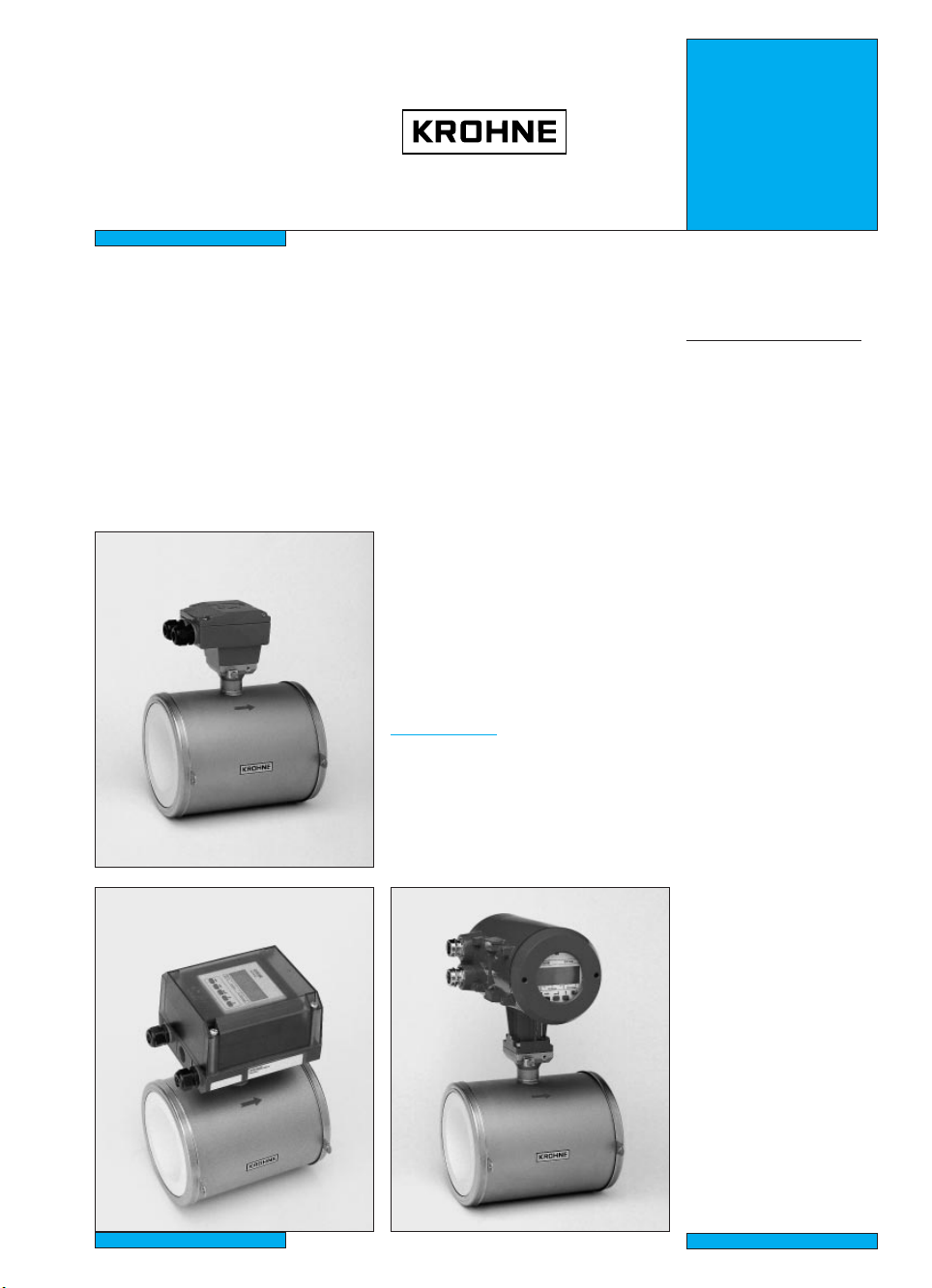
IFS 5000 F
PROFIFLUX
IFS 5000 F
IFM 5010 K
IFM 5020 K
IFM 5080 K
1010 K
IFM 1080 K
IFM 5010 K IFM 5080 K
3.1M46EA1 059821 Order No. DIN size 7.02142.31.00
US size 7.02142.71.00
0.73.00
Page 2

Contents
System description 2
Product liability and warranty 2
Standards and approvals 2
Items included with supply 3
1 Important information for installation: PLEASE NOTE 4-5
2 Suggestions for installation 5
3 Instrument nameplate 6
4 Flowmeter versions 6
5 Installation in the pipeline 7
6 Torques 8
7 Grounding 8-9
8 Replacement of separate primary head IFS 1000 F 10
9 Spares and order numbers 10
10 Technical data 11
11 Dimensions and weights 12-13
Notes 14
Printed form to accompany flowmeters returned to Krohne 15
System description
PROFIFLUX electromagnetic flowmeters are precision measuring instruments designed for the
linear flow measurement of process liquids.
1
The process liquids must be electrically conductive: ≥ 05 µS/cm (≥ 10 µS/cm for DN 2.5/
/10”)
≥ 20 µS/cm for demineralized cold water
The full-scale range Q
DN 2.5 - 100 /
1
/10” - 4” Q
can be set as a function of the meter size:
100%
= 0.01 - 340 m3/hr = 0.03 - 1500 US Gal/min
100%
This is equivalent to a flow velocity of 0.3 - 12 m/s, or 1 - 40 ft/s.
Product liability and warranty
PROFIFLUX electromagnetic flowmeters are designed solely for measuring the volumetric
flowrate of electrically conductive, liquid process products.
Special codes and regulations apply to their use in hazardous locations, and these are referred to
in the special “Ex” installation and operating instructions (supplied only with hazardous-duty
equipment).
Responsibility as to suitability and intended use of these electromagnetic flowmeters rests solely
with the operator.
Improper installation and operation of the flowmeters (systems) may lead to loss of warranty.
In addition, the “General conditions of sale” forming the basis of the purchase contract are
applicable.
If PROFIFLUX flowmeters need to be returned to Krohne, please note the information given on
the last-but-one page of this manual. Krohne regret that they cannot repair or check your
flowmeter(s) unless accompanied by the completed form sheet.
Standards and approvals
Please refer to the installation and operating instructions for the signal converter.
2
Page 3
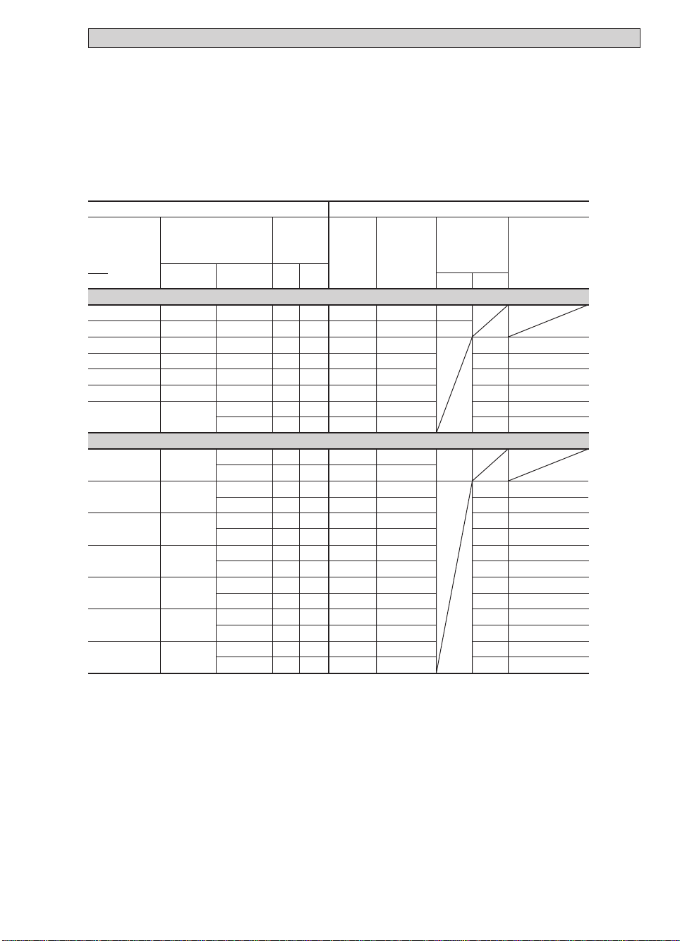
Items included with supply
IFS 5000 F
primary head
• primary head
in the size as ordered
• certificate of calibration data
• installation material as specified
in the following table
• installation instructions
Flowmeter
Size of
measuring
tube
to ...
... DIN 2501 (BS 4504)
DN 002.5 – 10
DN 015
DN 025
DN 040
DN 050
DN 080
DN 100
000
... ANSI B 16.5
1
/10”–3/8”
1
/2”
1”
11/2”
2”
3”
4”
Pipe flanges
Meter sizes
DN 010,15
DN 015
DN 025
DN 040
DN 050
DN 080
DN 100
1
/2”
1
/2”
1”
11/2”
2”
3”
4”
Pressure rating
flange class
PN 40
PN 40
PN 40
PN 40
PN 40
PN 40
PN 16
PN 25
150 lb
300 lb
150 lb
300 lb
150 lb
300 lb
150 lb
300 lb
150 lb
300 lb
150 lb
300 lb
150 lb
300 lb
IFM 5010 K, IFM 5020 K and IFM 5080 K
compact flowmeters
• compact flowmeter
in the size as ordered
• certificate of calibration data
• installation material as specified
in the following table
• installation instructions
• installation and operating instruc-
tions for the signal converter
max. allowable
operating
pressure
1)
bar psig
≤
580
≤ 40
≤
580
≤ 40
≤
580
≤ 40
≤
580
≤ 40
≤
580
≤ 40
≤
580
≤ 40
≤
230
≤ 16
≤
360
≤ 25
≤
290
≤ 20
≤
580
≤ 40
≤
290
≤ 20
≤
580
≤ 40
≤
290
≤ 20
≤
580
≤ 40
≤
290
≤ 20
≤
580
≤ 40
≤
290
≤ 20
≤
580
≤ 40
≤
290
≤ 20
≤
580
≤ 40
≤
290
≤ 20
≤
360
≤ 25
Scope of supply ...
... with
centering
material
2
2 xring
2 xring
4 xsleeve
4 xsleeve
6 xsleeve
6 xsleeve
6 xsleeve
2
2 xring
4 xsleeve
2 xring
4 xsleeve
4 xsleeve
4 xsleeve
4 xsleeve
4 xsleeve
6 xsleeve
4 xsleeve
6 xsleeve
6 xsleeve
6 xsleeve
... with
stud bolts
x
ring
4 xM12
4 xM12
4 xM12
x
M16
4
4 xM16
8 xM16
8 xM16
8 xM20
x
ring
1
x
4
1
x
4
1
x
4
1
x
4
1
x
4
5
x
4
1
x
4
3
x
4
5
x
4
5
x
8
5
x
4
3
x
8
5
x
8
3
x
8
X =Standard O = Option
... with 2)
grounding
rings E and
gaskets ...
/2”
/2”
/2”
/2”
/2”
/8”
/2”
/4”
/8”
/8”
/8”
/4”
/8”
/4”
D1
X
X
X
X
D1+D2
O
O
O
O
O
O
O
O
O
O
O
O
O
O
O
O
O
O
... without 2)
grounding
rings but with
gaskets D3
and wires V
X
X
X
X
X
X
X
X
X
X
X
X
X
X
X
X
X
X
1) For ANSI pipe flanges the max. allowable operating pressure is dependent on the process temperature,
see Sect. 10 “Technical data”.
2) For arrangement of gaskets and connection of wires V, see Section 7 “Grounding”.
3
Page 4
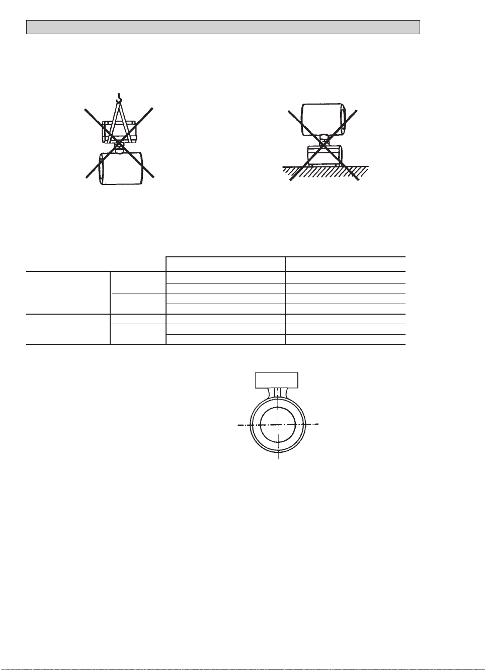
1 Important information for installation: PLEASE NOTE
• Handling
Do not lift flowmeter by the
signal converter housing or
Do not set flowmeter down on signal
converter housing or terminal box.
the terminal box.
• Use only solventless detergents to clean the signal converter housing (polycarbonate).
• Temperatures
For operating pressure and vacuum load based on flange standards, see Section 10
“Technical data“.
Ambient temperature Process temperature
Compact systems Standard -25 to +60 °C (-13 to +140 °F) -60 to +060 °C (-76 to +140 °F)
-25 to +40 °C (-13 to +104 °F) -60 to +140 °C (-76 to +284 °F)
EEx-version -25 to +60 °C (-13 to +140 °F) -20 to +160 °C (- 4 to +140 °F)
-25 to +40 °C (-13 to +104 °F) -20 to +140 °C (- 4 to +284 °F)
IFS 5000 F (separate): Standard -25 to +60 °C (-13 to +140 °F) -60 to +180 °C (-76 to +356 °F)
EEx version -25 to +60 °C (-13 to +140 °F) -20 to +160 °C (- 4 to +140 °F)
-25 to +40 °C (-13 to +104 °F) -20 to +150 °C (- 4 to +302 °F)
• Location and position as required,
but electrode axis X – • – • – • – X
must be approximately horizontal in a
Y
horizontal pipe run.
Y terminal box or converter housing
X
X
• Measuring tube must be completetly filled at all times.
• Direction of flow is arbitrary. Arrow on flowmeter can normally be ignored.
For exceptions, refer to Section ”Factory settings” in the installation and operating
instructions for the signal converter.
• Stud bolts and nuts: to fit, make sure there is sufficient room next to the pipe flanges.
• Vibration: support the pipeline on both sides of the compact flowmeter.
Level of vibration in conformity with IEC 068-2-34:
20-500 Hz, ran dom / 2 g rms / 30 minutes / x, y, z directions.
• Do not expose to direct sunlight,
fit a sunshade if necessary, not included with flowmeter, to be provided by customer.
4
Page 5
• Strong electromagnetic fields, avoid in vicinity of flowmeter.
• Straight inlet run minimum of 5 ××DN and outlet run minimum of 2 ××DN,
(DN = meter size), measured from the electrode axis.
• Vortex and corkscrew flow: increase length of inlet and outlet runs or install
flow conditioners.
• Mixing different process liquids: install flowmeter upstream of mixing point or at an
adequate distance downstream (minimum of 30 x DN), otherwise display may be unsteady.
• Plastic pipes and internally coated metal pipelines: grounding rings required,
see Section 7 ”Grounding”.
• Insulated pipeline: do not insulate flowmeter.
• Zero setting not necessary. To check, it should be possible to set ”zero” flow velocity
in the completely filled measuring tube. Shutoff valves should therefore be provided either
downsteam of the flowmeter or upsteam and downstream of the flowmeter.
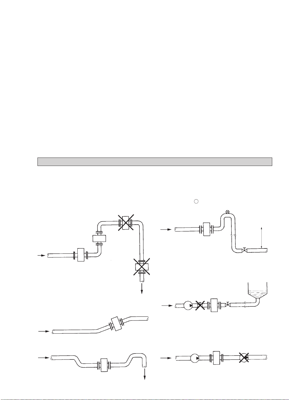
2 Suggestions for installation
To avoid measuring errors due to gas/air inclusion or to pipe runing empty please observe the
following:
Highest point of pipe run
(Air bubbles collect in measuring
tube - faulty measurements!)
Preferred
locations
Downpipe
”Zero” flow
velocity.
Line drained.
Faulty
measurements!
Horizontal pipe run
Install in slightly ascending pipe section. If not
possible, assure adequate velocity to prevent air,
gas or vapor from collecting in
upper part of flow tube.
Open feed or discharge
Install meter in low section of pipe.
Downpipe over 5 m (16 ft) length
Install air valve X downstream of
flowmeter.
Long pipeline
Always install control and shutoff valves
downstream of flowmeter.
Pumps
Never install flowmeter on pump suction side.
> 5m
> 16 ft
open discharge
5
Page 6

3 Instrument nameplate
IFS 5000 F
separate primary head
Magnetic field frequency
(here 1/6 of power frequency
Flange pressure rating
or flange class
Series-No.
Primary head
constant
Meter size
DN in mm and
inch equivalent
Type designation
Holland
Altometer
A 97 00000
GK: 1.918
DN50/2”-AL-PT PN 40 BAR
Liner
Fusel aluminium
oxide, 99.7% Al2O
3
Elektrode material
DN 2.5-15/
DN 25-100/1”-4” Platinum (PT)
IFS 5000 F / 6
TAG: 1234567-89
ISO KL. H IP 67
1
/10”-1/2” CERMET
Instrument nameplate for compact flowmeters
see installation and operating instructions for the signal converter.
4 Flowmeter versions
Tag No.
Protection category
to IEC 529 / EN 60529
Insulation class
of field coils
IFS 5000 F Separate primary head (F) , electrically connected to the signal
converter by signal and field current cables.
IFM 5010 K Compact flowmeter (K), IFC 010 K or IFC 020 K signal converter mounted direct
IFM 5020 K on the primary head.
IFM 5080 K Compact flowmeter (K), IFC 090 K signal converter mounted direct
on the primary head.
Versions for hazardous locations
IFS 5000 F and IFM 5080 K are approved as electrical equipment to the harmonized European
Standards and to Factory Mutual (FM).
Test certificate, certificate of conformity and wiring instructions for these devices are attaches to
the “Ex” installation instructions, provided only with hazardous-duty equipment.
6
Page 7

5 Installation in the pipeline
• Installation material, refer to table on page 3.
• Pipe flanges, and torques,
see Sect. 6, Page 7.
• Pipe flange spacing (fitting dimension)
Flowmeter Fitting dimensions “a” in mm (inch)
Meter size with without
DN mm inch grounding rings grounding rings
2.5 - 15
25 1 68 (2.68) 2) 58 (2.28) 3)
40 1 1/2” 93 (3.66) 2) 83 (3.27) 3)
50 2 113 (4.45) 2) 103 (4.06) 3)
80 3 163 (6.42) 2) 153 (6.02) 3)
100 4 213 (8.39) 2) 203 (7.99) 3)
1
/10” - 1/2” 65 (2.56) 1) –
1) plus 2 x thickness of gasket D2 between grounding rings and pipe flanges,
gasket D2 not included with supply, customer supplied.
2) incl. gasket D2 between grounding rings and pipe flanges.
3) incl. gasket D3 between measuring tube and pipe flanges.
• For arrangement of gaskets, see Sect. 7 “Grounding”.
• Dimensions and order numbers of gaskets, see Sect. 9 and 11.
• High-temperature pipelines
Where process temperatures exceed 100 °C/212 °F, provide for facilities to
compensate for longitudinal expansion on heat-up of the pipeline.
For short pipelines use resilient gaskets and
for long pipelines install flexible pipe elements (e.g. elbows).
• Position of flanges • Arrangement of centering sleeves
Install flowmeter in line with the pipe 1 washer
axis. Pipe flange faces must be 2 centering sleeve (≥ DN 40 / ≥ 1
1
parallel to each other, 3 stud bolt
max. permissible deviation: 4 hex. nut
L
- L
max
≤ 0,5 mm
min
≤ 0.02”
L
max
/2”)
L
min
7
Page 8

6 Torques
Flowmeter
Size of
measuring
tube
to ...
... DIN 2501 (BS 4504)
DN 002.5 – 10
DN 015
DN 025
DN 040
DN 050
DN 080
DN 100
000
... ANSI B 16.5
1
/10”–3/8”
1
/2”
1”
1
/2”
1
2”
3”
4”
Pipe flanges
Meter sizes Pressure rating
DN 010,15
DN 015
DN 025
DN 040
DN 050
DN 080
DN 100
1
/2”
1
/2”
1”
1
/2”
1
2”
3”
4”
flange class
PN 40
PN 40
PN 40
PN 40
PN 40
PN 40
PN 16
PN 25
150 lb
300 lb
150 lb
300 lb
150 lb
300 lb
150 lb
300 lb
150 lb
300 lb
150 lb
300 lb
150 lb
300 lb
max. allowable
operating
pressure
bar psig
≤ 40 ≤ 580
≤ 40 ≤ 580
≤ 40 ≤ 580
≤ 40 ≤ 580
≤ 40 ≤ 580
≤ 40 ≤ 580
≤ 16 ≤ 230
≤ 25 ≤ 360
≤ 20 ≤ 290
≤ 40 ≤ 580
≤ 20 ≤ 290
≤ 40 ≤ 580
≤ 20 ≤ 290
≤ 40 ≤ 580
≤ 20 ≤ 290
≤ 40 ≤ 580
≤ 20 ≤ 290
≤ 40 ≤ 580
≤ 20 ≤ 290
≤ 40 ≤ 580
≤ 20 ≤ 290
≤ 25 ≤ 360
1)
Max. allowable torques
with gaskets made
of ...
...Gylon
Nm
22
47
58
48
75
94
24
30
38
57
58
30
98
59
75
92
...Chemotherm
Nm Nmftxlb ftxlb ftxlb
032
16
066
34
082
42
069
35
106
54
133
68
033
17
042
22
054
28
081
41
083
42
042
22
138
71
084
43
108
54
131
67
...e.g. builtup material
023
048
059
050
077
096
024
030
039
059
060
030
100
061
078
095
2)
3)
4)
23
32
36
35
35
35
35
5)
23
5)
25
5)
25
5)
25
5)
25
5)
1) For ANSI pipe flanges the max. allowable operating pressure is dependent on the process
temperature, see Sect. 10 “Technical data”.
2) Arrangement of gaskets, see Sect. 7 “Grounding”
3) Size of gaskets D2, see Sect. 11.
4) The max.allowable torque is dependent on the gasket material, 10 Nm ~1.0 kpm = 7.23 ft
x
5) Gaskets D1 are special O-rings, for Order No. see Sect. 9.
7. Grounding
• Warning: All flowmeters must be properly grounded to avoid personnel shock hazard.
• The ground conductor should not transmit any interference voltages, therefore do not ground
any other electrical devices together with this conductor.
IFS 5000 F separate primary head with terminal box
• A functional ground FE must always be connected.
• Signal converters with a field power supply of > 125 mA / > 60 V:
IFS 5000 F primary head: because of the higher field current from the signal converter, a PE
protective conductor must be connected to the primary head, see grounding diagrams below.
8
lbf
Page 9

Compact systems
pply power > 50 V AC
Su
• Grounding is via the PE protective ground conductor incorporated in the power supply
cable, see also Section “Connection to power” in the installation
and operating instructions
for the signal converter.
• EXCEPTION: Do not connect up the PE protective ground conductor in the terminal
box if e.g. compact units are operated in the proximity of electric furnaces, electrolysis
plants, etc., and large potential differences occur in the pipeline system. An FE functional
ground must simultaneously take over the function of the protective conductor (combined
protective/functional ground). Refer to appropriate national codes for specific requirements
for this type of installation, which may require the addition of a ground fault detection
circuit interrupter.
Power su
pply 24 V AC or DC
• Protective separation (PELV) must be ensured (VDE 0100/VDE 0106 or IEC 364/IEC 536
or equivalent national regulations).
• An FE functional ground conductor must be connected for measurement reasons.
Grounding diagrams
with or without internal coating,
Metal pipelines,
and plastic pipelines
grounding with grounding rings
grounding without grounding rings
Metal pipelines,
not internally coated
Y Y
V*
R
DN 25 - 100 / 1” - 4”
”
2
/
1
” -
10
/
1
DN 2.5 - 15 /
RF RF
E
D2 D2
D1 D1
FE (PE)
Y
RR
RF
E/D1
D2 D2
FE (PE)
V* not required for plastic pipelines
V*
E
E/D1
R
D1/D3 Gaskets glued to measuring tube.
D2 Gaskets not included in supply, to
E Grounding rings (option) with glued-
E/D1 Grounding rings, screwed to housing,
RF
FE Functional ground, conductor
PE Protective conductor, required if the
R Pipeline
RF Pipe flanges
V Interconnecting wires, bolted to
Y Terminal box or signal converter.
VV
RR
RF
FE (PE)
RF
D3D3
be provided by customer.
Use standard flat gaskets, dimensions
see Sect. 11.
on gaskets D2, supplied loose and must
be screwed to the housing.
with inserted gaskets D1,
special O-rings.
≥ 4 mm2Cu/AWG 10.
IFS 5000 F is operated with a signal
converter that supplied a field current of
> 125 mA / > 60 V.
housing.
9
Page 10

8 Replacement of the separate primary head
Switch off power source before commencing work!
1) Note down terminal assignment before dismantling the “old“ primary head.
2) Install the new primary head as described in the supplied installation instructions.
3) Make electrical connection at the signal converter as described in the installation and
operating instructions for the signal converter.
4) Specific calibration data are defined during factory calibration for each primary head,
which are indicated on the instrument nameplate.
This includes the primary constant GK and the magnetic field frequency. These data
need to be reset in the signal converter.
5) If the size of primary head is also different from the old one, the full-scale range Q
100%
the meter size will need to be reset.
6) After resetting the signal converter, carry out a zero point check.
7) If necessary, reset the internal electronic totalizer of the signal converter.
9 Spare parts and order numbers
Gaskets D1: O = O-rings
F = flat rings
Material: G = Gylon 3500
C = Chemotherm (graphite)
(Gasket arrangement, see Sect. 7)
and
Meter size
mm inch
2.5 - 15
1
25 1
40 1
50 2
80 3
100 4
10
/10 - 1/2
1
/2
Version,
material
O
EPDM
Kalrez
F
F
F
F
F
Viton
G
C
G
C
G
C
G
C
G
C
Order No.
5.30020.03
5.30020.04
5.30023.02
5.30823.06
5.30823.01
5.30823.07
5.30823.02
5.30823.08
5.30823.03
5.30823.09
5.30823.04
5.30823.10
5.30823.05
Page 11

10. Technical data
Electrical conductivity
DN 2.5, 1/10” ≥ 10 µS/cm
DN 4 - 100, 1/8” - 4” ≥ 5 µS/cm
Temperatures Ambient temperature Process temperature
Compact systems: Standard -25 to +60 °C (-13 to +140 °F) -60 to +060 °C (-76 to +140 °F)
-25 to +40 °C (-13 to +104 °F) -60 to +140 °C (-76 to +284 °F)
EEx version -25 to +60 °C (-13 to +140 °F) -20 to +060 °C (- 4 to +140 °F)
-25 to +40 °C (-13 to +104 °F) -20 to +140 °C (- 4 to +284 °F)
IFS 5000 F (separate) Standard -25 to +60 °C (-13 to +140 °F) -60 to +180 °C (-76 to +356 °F)
EEx version -25 to +60 °C (-13 to +140 °F) -20 to +060°C (- 4 to +140 °F)
-25 to +40 °C (-13 to +104 °F) -20 to +150 °C (- 4 to +302 °F)
Temperature change DN 2.5-15/
Temperature rising in 10 minutes: ∆ T = 150 °C or 302 °F ∆ T = 150 °C or 302 °F
for sudden change: ∆ T = 120 °C or 248 °F ∆ T = 120 °C or 248 °F
Temperature falling in 10 minutes: ∆ T = 120 °C or 248 °F ∆ T = 100 °C or 212 °F
for sudden change: ∆ T = 190 °C or 194 °F ∆ T = 180 °C or 176 °F
Max. operating pressure (at product temperature ≤ 180 °C/≤ 356 °F)
DN 2.5 - 80 40 bar or 580 psig
DN 100 16 bar or 230 psig (option 25 bar/360 psig)
1
/10” - 4” 16 bar or 230 psig, for 150 lb pipe flanges
1
/10” - 3” 40 bar or 580 psig, for 300 lb pipe flanges (option)
4” 25 bar or 360 psig, for 300 lb pipe flanges (option)
Vacuum load 0 mbar abs. or 0 psia
Insulation class of field coils H
Electrode design fused-fitted electrodes
Power supply for field coils max. 60 V from signal converter
Protection category (IEC 529 / EN 60 529) IP 67, equivalent to NEMA 6
Materials
Measuring tube Fused aluminium oxide, 99.7% Al2O
Electrodes DN 2.5 - 15 / 1/10” - 1/2” CERMET
DN 25 - 100 / 1” - 4” Platin
Housing
DN 2.5 - 15 /1/10” - 1/2” stainless steel 1.4462/Duplex
DN 25 - 100, 1” - 4” stainless steel 1.4301 or SS 304 - AISI
Terminal box Die-cast aluminium, with polyurethane finish
Grounding rings stainless steel 1.4571 or SS 316 Ti - AISI, others on request
Gaskets between primary head
and grounding rings
DN 2.5 - 015 /1/10” - 1/2” Viton O-rings, optionally EPDM or Kalrez
DN 25 - 100, 1” - 4” Gylon 3500 (beige) gaskets
(application range similar to that of PTFE),
optionally Chemotherm (graphite) gaskets
Gaskets between primary head or grounding rings
and pipe flanges (DN 25 to 100, 1” - 4”) Gylon 3500 (beige) gaskets
(application range similar to that of PTFE),
optionally Chemotherm (graphite) gaskets
Centering material
DN 2.5 - 25 /1/10” - 1” EPDM rings
DN 40 - 100 / 11/2” - 4” Rubber sleeves
Stud bolts Steel electrogalvanized,
as option stainless steel 1.4301 or SS 304 - AISI
≥ 20 µS/cm for demineralized cold water
}
1
/10”-1/2” DN 25-100/1”-4”
3
11
Page 12

11 Dimensions and weights
Meter size Dimensions in mm and (inch)
Approx. weight in
DN mm inch a b
max
d e kg (lb)
2.5 – 15
1
/10 – 1/2 65 (2.56) 137 (5.39) 51 (2.01) 44 (1.73) 1.6 (3.53)
25 1 68 (2.68) 130 (5.12) 34 (1.34) 102 (4.02) 1.6 (3.53)
40 1
1
/2 93 (3.66) 145 (5.71) 42 (1.65) 117 (4.61) 2.4 (5.29)
50 2 113 (4.45) 163 (6.42) 51 (2.01) 135 (5.31) 2.9 (6.39)
80 3 163 (6.42) 195 (7.68) 67 (2.64) 167 (6.57) 6.4 (14.11)
100 4 213 (8.39) 220 (8.66) 79 (3.11) 1 92 (7.56) 8.8 (19.40)
Meter size DN 2.5 – 15 and 1/10” – 1/2”: Pipe flanges DN 15 / PN 40 or 1/2” / Class 150 lb (300 lb).
Necessary flange spacing
DN 2.5 – 15,
1
/10” – 1/2”: Dimension a + 2 times gasket thickness (gasket between grounding rings and pipe flanges)
DN 25 – 100, 1” – 4”:
without grounding rings: Dimension a incl. gaskets between primary head and pipe flanges
with grounding rings (option): Dimension a + 10 mm or a + 0.4”, incl. gaskets between grounding rings and pipe flanges.
PLEASE NOTE
The total dimension for the height is obtained from dimension b (see table) plus the height
The total weight is made up of the weight of the signal converter (see table)
of the terminal box or the signal converter, see drawings.
plus the weight of the terminal box or signal converter, see below.
Terminal box
Weight approx.
0.5 kg (1.1 lb)
12
IFC 010 K and IFC 020 K
signal converters
Weight approx.
1.6 kg (3.6 lb)
IFC 090 K
signal converter
Weight approx.
2.3 kg (5.1 lb)
Page 13

160 (6.30,,)
136 (5.35,,)
098 (3.86,,)
208 (8.19,,) Ex: 238 (9.37,,)
140 (5.51,,)
078 (3.07,,)
a
071 (2.80
,,
)
105 (4.13
,,
)
165 (6.50
,,
)
d
e
b
b
c
160 (6.30,,)
136 (5.35,,)
098 (3.86,,)
208 (8.19,,) Ex: 238 (9.37,,)
140 (5.51,,)
078 (3.07,,)
071 (2.80
,,
)
105 (4.13
,,
)
165 (6.50
,,
)
e
d
Dimensions of gaskets D2
Meter size to ... Dimensions
... DIN 2501 ... ANSI B 16.5 dia. d
1
DN 2.5-15
/10”-1/2” commercial
out
Use
flat gaskets
dia. d
in
DN 025 1” 046 (1.81) 026 (1.02)
DN 040 11/2” 062 (2.41) 039 (1.54)
DN 050 2” 074 (2.91) 051 (2.01)
DN 080 3” 106 (4.17) 080 (3.15)
DN 100 4” 133 (5.24) 101 (3.98)
(thickness of the gaskets
approx. 1.6 mm / 0.06”)
DN 2.5 - 15 / 1/10” - 1/2”
Dimensions in mm (in)
DN 25 - 100 / 1” - 4”
13
Page 14

Notes
14
Page 15

If you need to return flowmeters for testing
or repair to Krohne
Your electromagnetic flowmeter
• has been carefully manufactured and tested by a company
with ISO 9001 certification
• and volumetrically calibrated in one of the world’s most
accurate test rigs.
If installed and operated in accordance with these operating
instructions, your flowmeter will rarely present any problems.
Should you nevertheless need to return a flowmeter for
checkout or repair, please pay strict attention to the following
:
points
Due to statutory regulations concerning protection of the envi-
ronment and the health and safety of our personnel, Krohne
may only handle, test and repair returned flowmeters that
have been in contact with liquids if it is possible to do so without risk to personnel and environment. This means that
Krohne can only service your flowmeter if it is accompanied
by a certificate in line with the following model confirming that
the flowmeter is safe to handle.
If the flowmeter has been operated with toxic, caustic,
flammable or water-endangering liquids, you are kindly
requested
• to check and ensure, if necessary by rinsing or neutralizing, that all cavities in the flowmeter are free from such
dangerous substances.
(Directions on how you can find out whether the primary
head has to be opened and then flushed out or neutralized
are obtainable from Krohne on request.)
• to enclose a certificate with the flowmeter confirming that
the flowmeter is safe to handle and stating the liquid used.
Krohne regret that they cannot service your flowmeter unless
accompanied by such a certificate.
SPECIMEN certificate
Company: Address:
Department: Name:
Tel. No.:
The enclosed electromagnetic flowmeter
Type: Krohne Order No. or Series No.:
has been operated with the following liquid:
Because this liquid is
water-endangering * / toxic * / caustic * / flammable *
we have
– checked that all cavities in the flowmeter are free from such substances *
– flushed out and neutralized all cavities in the flowmeter *
(* delete if not applicable)
We confirm that there is no risk to man or environment through any residual liquid contained in this flowmeter.
Date: Signature:
Company stamp:
15
 Loading...