

Page 1
09/97
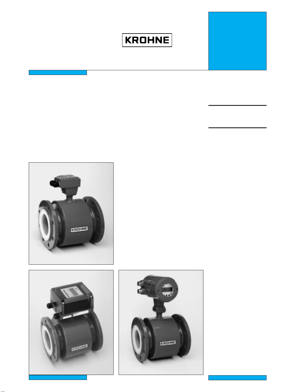
Electromagnetic
Installation
instructions
flowmeters
• Primary heads
• Compact flowmeters
IFS 4000 F / IFS 4005 F
ALTOFLUX
IFS 4000 F
IFS 4005 F
IFM 4010 K
IFM 4020 K
IFM 4080 K
IFM 4010 K / IFM 4020 K IFM 4080 K
3.1M48EA2 099721 Order No. DIN size 7.02147.32.00
US size 7.02147.72.00
Page 2

Contents
System description 2
Product liability and warranty 2
Standards and approvals 2
Items included with supply 3
1 Important information for installation: PLEASE NOTE 4-5
2 Suggestions for installation 5
3 Instrument nameplate 6
4 Flowmeter versions 6
5 Installation in the pipeline 7
6 Torques 8
7 Grounding 9
8 Replacement of separate primary head 10
9 Technical data 10-11
10 Dimensions and weights 12-13
11 Limits 14
Printed form to accompany flowmeters returned to Krohne 15
System description
ALTOFLUX electromagnetic flowmeters are precision measuring instruments designed for the
linear flow measurement of process liquids.
The process liquids must be electrically conductive: ≥ 05 µS/cm
≥ 20 µS/cm for demineralized cold water
The full-scale range Q
IFM 4010 K, IFM 4020 K, IFM 4080 K: DN 10 - 1000 / 3/8” - 040” Q
IFS 4000 F: DN 10 - 3000 /
IFS 4005 F: DN 50 - 1000 / 2” - 040” Q
can be set as a function of the meter size:
100%
3
/8” - 120” Q
= 0.1 - 033900 m3/hr = 0.02 - 1156640 USGPM
100%
= 0.1 - 305000 m3/hr = 0.02 - 1400000 US GPM
100%
= 2.1 - 033900 m3/hr = 9.80 - 1156640 US GPM
100%
This is equivalent to a flow velocity of 0.3 - 12 m/s, or 1 - 40 ft/s.
Product liability and warranty
ALTOFLUX electromagnetic flowmeters are designed solely for measuring the volumetric flowrate
of electrically conductive, liquid process products.
Special codes and regulations apply to their use in hazardous locations, and these are referred to
in the special ”Ex” installation and operating instructions (supplied only with hazardous-duty
equipment).
Responsibility as to suitability and intended use of these electromagnetic flowmeters rests solely
with the operator.
Improper installation and operation of the flowmeters (systems) may lead to loss of warranty.
In addition, the ”General conditions of sale” forming the basis of the purchase contract are
applicable.
If ALTOFLUX flowmeters need to be returned to Krohne, please note the information given on the
last-but-one page of this manual. Krohne regret that they cannot repair or check your flowmeter(s)
unless accompanied by the completed form sheet.
Standards and approvals
Please refer to the installation and operating instructions for the signal converter.
2
Page 3
Items included with supply
IFS 4000 F / IFS 4005 F
primary heads
• Primary head in the size as ordered
• Connecting wires for grounding, refer
to Section 7 ”Grounding”
• Certificate of calibration data
• Grounding rings (optional), if ordered
• Installation instructions
Fitting accessories (stud bolts, nuts, gaskets, etc.) are not supplied with the flowmeter,
to be provided by customer!
IFM 4010 K, IFM 4020 K and IFM 4080 K
compact flowmeters
• Compact flowmeter in the size as ordered
• Connecting wires for grounding, see
Section 7 ”Grounding”
• Certificate of calibration data
• Grounding rings (optional), if ordered
• Installation instructions
• Installation and operating instructions
for the signal converter
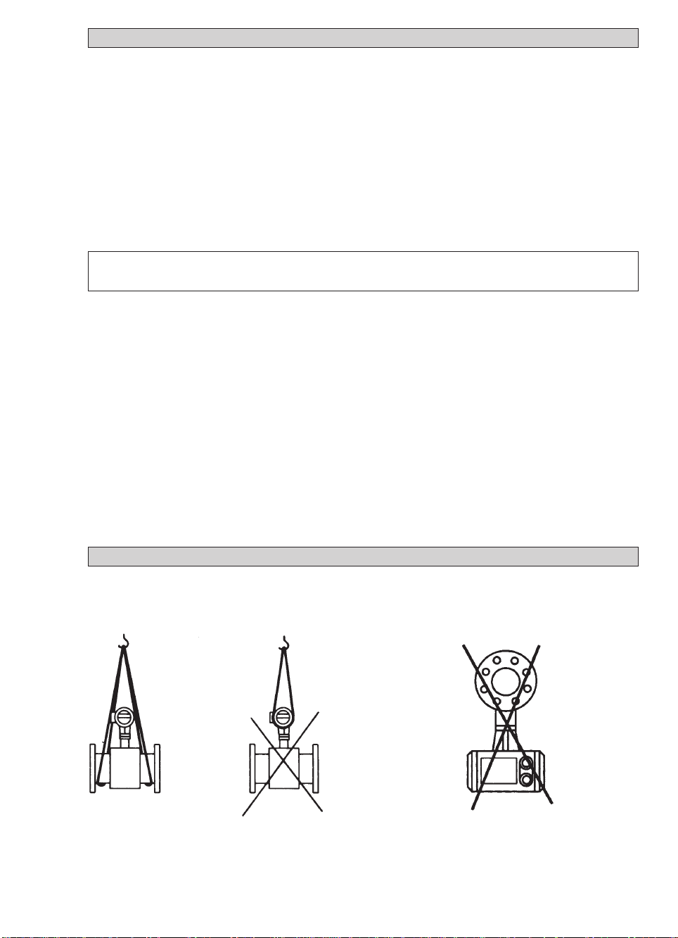
Do not lift flowmeter by the signal converter
housing or the terminal box.
Handling
Do not set flowmeter down on signal
converter housing or terminal box.
3
Page 4
1 Important information for installation: PLEASE NOTE !
• Use only solventless detergents to clean the signal converter housing (polycarbonate).
• Temperatures
Refer to Section 11 ”Limits” for operating pressure and vacuum load based on flange
standards and type of tube liner.
Ambient temperature Process temperature
Compact systems -25 to +60 °C (-13 to +140 °F) -25 to ≤ +60 °C (-13 to ≤ +140 °F)
-25 to +40 °C (-13 to +104 °F) -25 to > +60 °C (-13 to > +140 °F)
IFS 4000 F
IFS 4005 F -25 to +60 °C (-13 to +140 °F) -25 to > +60 °C (-13 to > +140 °F)
In storage -25 to +60 °C (-13 to +140 °F) with liners made of
Teflon®-PFA, Teflon®-PTFE, FEP, Tefzel, Irathane and soft rubber
-20 to +60 °C (-04 to +140 °F), kept immobile,
with Neoprene liner
Transport -25 to +60 °C (-13 to +140 °F), with liners made of
Teflon®is a registered trademark of Du Pont
®
Teflon
-PFA, Teflon®-PTFE, FEP, Tefzel, Irathane and soft rubber
-05 to +50 °C (-04 to +140 °F),
with Neoprene liner
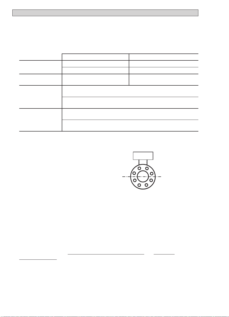
• Location and position as required,
but electrode axis X – • – • – • – X
Y
must be approximately horizontal in a
horizontal pipe run.
Y terminal box or converter housing
X
X
• Measuring tube must be completetly filled at all times.
• Direction of flow is arbitrary. Arrow on flowmeter can normally be ignored.
For exceptions, refer to Section ”Factory settings” in the installation and operating
instructions for the signal converter.
• Stud bolts and nuts: to fit, make sure there is sufficient room next to the pipe flanges.
• Vibration: support the pipeline on both sides of the compact flowmeter.
Level of vibration in conformity with IEC 068-2-34: below 2.2g for compact flowmeters
in the frequency range of 20-50 Hz with the IFC 010 K
/ IFC 020 K and 20-150 Hz
with the IFC 090 K.
• Do not expose to direct sunlight,
fit a sunshade if necessary, not included with flowmeter, to be provided by customer.
• Large meter sizes (≥≥DN 200 / ≥≥8”): use adapter pipes to allow axial shifting of the
counterflanges and to facilitate installation.
4
Page 5
• Strong electromagnetic fields, avoid in vicinity of flowmeter
• Straight inlet run minimum of 5 ××DN and outlet run minimum of 2 ××DN,
(DN = meter size), measured from the electrode axis.
• Vortex and corkscrew flow: increase length of inlet and outlet runs or install
flow conditioners.
• Mixing different process liquids: install flowmeter upstream of mixing point or at an
adequate distance downstream (minimum of 30 × DN), otherwise display may be unsteady.
• Plastic pipes and internally coated metal pipelines: grounding rings required,
see Section 7 ”Grounding”.
• Insulated pipeline: do not insulate flowmeter
• Zero setting not necessary. To check, it should be possible to set ”zero” flow velocity
in the completely filled measuring tube. Shutoff valves should therefore be provided
either downstream of the flowmeter or upstream and downstream of the flowmeter.
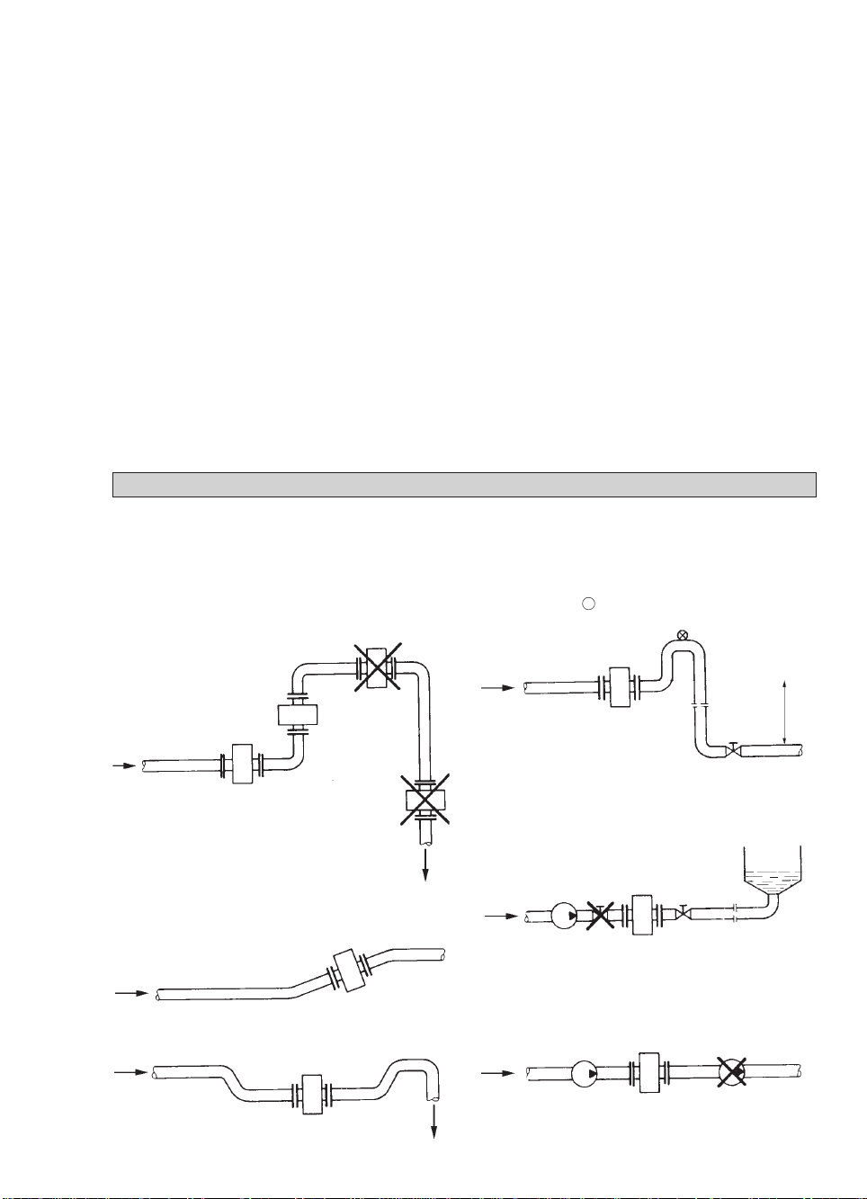
2 Suggestions for installation
To avoid measuring errors due to gas/air inclusion or to pipe running empty, please observe the
following:
Highest point of pipe run
(Air bubbles collect in measuring
tube - faulty measurements!)
Preferred
locations
Downpipe
”Zero” flow
velocity.
Line drained.
Faulty
measurements!
Horizontal pipe run
Install in slightly ascending pipe section. If not
possible, assure adequate velocity to prevent air,
gas or vapor from collecting in
uppper part of flow tube.
Open feed or discharge
Install meter in low section of pipe.
Downpipe over 5 m (16 ft) length
Install air valve X downstream of
flowmeter.
Long pipeline
Always install control and shutoff valves
downstream of flowmeter.
Pumps
Never install flowmeter on pump suction side.
> 5m
> 16 ft
open discharge
5
Page 6

3 Instrument nameplate
IFS 4000 F/IFS 4005 F
separate primary head
Altometer
Series No.
Primary head
constant
Meter size
DN in mm and
inch equivalent
A 97 00000
GK: 1.918
DN50/2”-PFA-HC PN 40 BAR
Liner
Teflon
Holland
®
PFA
Electrode material
Hastelloy C4
Type designation
IFS 4000 F / 6
TAG: 1234567-89
ISO KL. H IP 67
Flange pressure rating
or flange class
Magnetic field frequency
(here 1/6 of power frequency)
Tag No.
Protection category
to IEC 529 / EN 60529
Insulation class
of field coils
Liner materials
NE Neoprene
PFA Teflon®-PFA
PUI Irathane
T Teflon®-PTFE
TZ Tefzel
W Soft rubber
FEP FEP
Electrode materials
C Conductive rubber compound
HB Hastelloy B2
HC Hastelloy C4
IN Incoloy
M4 Monel 400
NI Nickel
PT Platinum
TA Tantalum
TI Titanium
V4A Stainless steel 1.4571 / SS 316-Ti
XX/TC xx with conductive,
XX = base material,
}
e.g. HC
®
Teflon
is a registered trademark of Du Pont
PTFE compound
XX/CO xx low-noise
version
Instrument nameplate for compact flowmeters
see installation and operating instructions for the signal converter.
4 Flowmeter versions
IFS 4000 F Separate primary head (F) , electrically connected to the signal
converter by signal and field current cables.
IFM 4005 F Separate primary head (F) , electrically connected to the signal converter
by signal and field current cables. Designed for higher field currents.
The double coil insulation (insulation class II) rules out the need for special
protective grounding.
IFM 4010 K, Compact flowmeter (K), IFC 010 K or IFC 020 K signal converter mounted direct
IFM 4010 K on the primary head.
IFM 4080 K Compact flowmeter (K), IFC 090 K signal converter mounted direct
on the primary head.
Versions for hazardous locations
IFS 4000 F and IFM 4080 K are approved as electrical equipment to the harmonized European
Standards and to Factory Mutual (FM).
Test certificate, certificate of conformity and wiring instructions for these devices are attached to
the ”Ex” installation instructions, provided only with hazardous-duty equipment.
6
Page 7

5 Installation in the pipeline
• Installation material not included, to be provided by customer (stud bolts,
nuts, gaskets, etc.)
• Pipe flanges and operating pressure: refer to tables on ”limits” in Section 11.
• Distance between pipe flanges
see fitting dimension ”a”, in Section 10 ”Dimensions and weights”.
• High-temperature pipelines
Where process temperatures exceed 100 °C/212 °F, provide for facilities to
compensate for longitudinal expansion on heat-up of the pipeline.
For short pipelines use resilient gaskets and
for long pipelines install flexible pipe elements (e.g. elbows).
• Position of flanges
Install flowmeter in line with the pipe
L
max
axis. Pipe flange faces must be
parallel to each other,
max. permissible deviation:
- L
min
≤≤
0.5 mm
L
max
≤ 0.02”
L
min
• Neoprene liners
Process temperatures below - 5 °C (+ 23 °F) are only permissible if the pipeline
is supported on both sides of the flowmeter and provided there is only slight
vibration and no water hammer in the pipe.
• Teflon
®
-PTFE liners
Install at the lowest point of the pipe run to avoid an excessive vacuum condition at
the meter. Do not remove or damage liner, which is formed around the flange edges.
• Irathane liner, thickness > 12 mm / > 0.50”
The nominal diameter of the pipe flanges must be greater than the nominal diameter
of the measuring tube, see tables in Section 10 ”Dimensions and weights”.
• Gaskets
Use gaskets suitable for the application and appropriate to the liner, not included
with flowmeter, to be provided by customer.
• Grounding rings / protective rings (option)
On plastic pipes and internally coated metal pipelines, grounding rings must form the
conductive connection with the fluid. Refer to Section 7 ”Grounding for electrical connection.
Groundin
g ring No. 1 Grounding ring, protective ring No. 2 Grounding ring, protective ring No. 3
3 mm/0.12” thick for flowmeters with Teflon®-PTFE with cylindrical neck, to protect the liner
liner, solidly fitted to the flanges, particularly at the inlet edge against
3 mm/0.12” thick abrasive products, 3 mm/0.12” thick.
Length: 130 mm/1.18”, for ≤ DN 300, ≤ 12“
100 mm/3.94”, for ≥ DN 350, ≥ 14“
Teflon®is a registered trademark of Du Pont.
7
Page 8

6 Torques
• Tighten stud bolts uniformly in diagonally opposite sequence, see table for number and type.
• Irathane liner, thickness > 12 mm / > 0.50”
The max. torque refers to the nominal diameter of the pipe flanges and not to the nominal
diameter of the measuring tube.
• Column A
Torques for Teflon®-PFA and Teflon®-PTFE liners.
• Column B
Torques for liners made of
Neoprene, Irathane, Tefzel, soft rubber and FEP.
• 10 Nm ~ 1.0 kpm ~ 7.23 ft ××lbf
Meter
size
DN
mm
10
15
20
25
32
40
50
65
65
80
100
125
150
200
200
250
250
300
300
350
400
450
500
600
700
800
900
1000
Pressure
rating
PN
40
40
40
40
40
40
40
16
40
25
16
16
16
10
16
10
16
10
16
10
10
10
10
10
10
10
10
10
Bolts
x
M 12
04
x
04
M 12
04 xM 12
04 xM 12
04 xM 16
04 xM 16
04 xM 16
04 xM 16
x
08
M 16
08 xM 16
08 xM 16
08 xM 16
08 xM 20
08 xM 20
12 xM 20
x
M 20
12
12 xM 24
12 xM 20
12 xM 24
16 xM 20
16 xM 24
20 xM 24
x
20
M 24
20 xM 27
20 xM 27
24 xM 30
28 xM 30
28 xM 35
003.5
003.5
014.8
026.7
013
024
043
034
061
086
097
119
133
130
199
182
265
242
380
–
–
Max. torque
Nm (ft xlbf)
(2.5)
(2.5)
(3.5)
(4.8)
(9.4)
(17.4)
(31.1)
(24.6)
(44.1)
(62.2)
(70.2)
(86.1)
(96.2)
(94.0)
(143.9)
(131.6)
(191.6)
(175.0)
(274.7)
003.6
003.6
014.8
014.4
012
023
039
031
051
069
079
104
093
091
143
127
180
161
259
269
269
Max. torque
Nm (ft x lbf)
AB A B
007.6
009.3
016
022
037
043
055
051
038
047
039
053
068
084
068
078
116
088
144
097
139
127
149
205
238
328
–
–
(5.5)
(6.7)
(11.6)
(15.9)
(26.8)
(31.1)
(39.8)
(36.9)
(27.5)
(34.0)
(28.2)
(38.3)
(49.2)
(60.7)
(49.2)
(56.4)
(83.9)
(63.7)
(104.2)
(70.1)
(100.5)
(91.8)
(107.7)
(148.2)
(172.1)
(237.1)
004.6
005.7
019.6
011
019
025
031
042
021
025
030
040
047
068
045
065
178
076
105
075
104
193
107
138
163
219
205
261
(3.3)
(4.1)
(6.9)
(8.0)
(13.0)
(18.1)
(22.4)
(30.4)
(15.2)
(18.1)
(21.7)
(28.9)
(34.0)
(49.2)
(32.5)
(47.0)
(56.4)
(54.9)
(75.9)
(54.2)
(75.2)
(67.2)
(77.4)
(99.8)
(117.8)
(158.3)
(148.2)
(188.7)
Meter
size
inch
3
/8
1
/2
3
/4
1
11/2
2
3
4
6
8
10
12
14
16
18
20
24
28
32
36
40
Body
pressure
rating
lb
580
580
580
580
580
580
360
230
230
145
145
145
145
145
145
145
145
145
145
145
145
Bolts
for ANSI
class 150
flanges
1
x
04
/2”
1
x
04
/2”
1
x
04
/2”
1
x
04
/2”
1
x
04
/2”
5
x
04
/8”
5
x
04
/8”
5
x
08
/8”
3
x
08
/4”
3
x
08
/4”
7
x
12
/8”
7
x
12
/8”
x
1”
12
16 x1”
16 x11/8”
20 x11/8”
20 x11/4”
28 x11/4”
28 x11/2”
x
11/2”
32
36 x11/2”
Note: Process pressure must not exceed ANSI
flange rating. Refer to ANSI Standard B 16.5.
(2.6)
(2.6)
(3.5)
(3.2)
(8.7)
(16.6)
(28.2)
(22.4)
(36.9)
(49.9)
(57.1)
(75.2)
(76.2)
(65.8)
(103.4)
(91.8)
(130.1)
(116.4)
(187.3)
(194.5)
(194.5)
Teflon®is registered trademark of Du Pont
8
Page 9

7 Grounding
• All flowmeters must be properly grounded to avoid personnel shock hazard.
• The ground conductor should not transmit any interference voltages, therefore do not ground
any other electrical devices together with this conductor.
IFS 4000 F and IFS 4005 F separate primary heads with terminal box
• An FE functional ground must always be connected.
• Signal converter field power supply > 125 mA / 60 V:
IFS 4005 F primary head: no special measures required.
IFS 4000 F primary head: because of the higher field current from the signal converter, a PE
protective conductor must be connected to the primary head, see grounding diagrams below.
IFM 4010 K, IFM 4020 K and IFM 4080 K compact systems
Su
pply power > 50 V AC
• Grounding is via the PE protective ground conductor incorporated in the power supply
cable, see also Section ”Connection to power” in the installation and operating instructions
for the signal converter.
• EXCEPTION:
Do not connect up the PE protective ground conductor in the terminal
box if e.g. compact units are operated in the proximity of electric furnaces, electrolysis
plants, etc., and large potential differences occur in the pipeline system. An FE functional
ground must simultaneously take over the function of the protective conductor (combined
protective/functional ground). Refer to appropriate national codes for specific requirements
for this type of installation, which may require the addition of a ground fault detection circuit
interrupter.
Power su
pply 24 V AC or DC
• Protective separation (PELV) must be ensured (VDE 0100 / VDE 0106 or
IEC 364 / IEC 536 or equivalent national regulations).
• An FE functional ground conductor must be connected for measurement reasons.
Grounding diagrams
Metal pipelines,
not internally coated
grounding without grounding rings
with or without internal coating,
Metal pipelines,
and plastic pipelines
grounding with grounding rings
YY
V1
RR
F
D3
FE
(PE)
D1, D2, D3 Gaskets, not included with supply, to be provided by customer.
E Grounding rings (option)
F Flowmeter flanges
FE
Functional ground, wire ≥ 4 mm2Cu (10 AWG), not included with flowmeter, to be provided by customer
PE Protective conductor required if the IFS 4000 F is operated with a signal converter that supplies a
field current of > 125 mA / > 60 V .
Wire ≥ 4 mm2Cu (10 AWG), not included with flowmeter, to be provided by customer.
R Pipeline
RF Pipe flanges
V1, V2 Interconnecting wires, included with flowmeter
Y Terminal box or signal converter
V1 V2 V2
RR
F
RFRF
D3 D2 D1 D1
EE
FE
(PE)
FF
RFRF
D2
9
Page 10

8 Replacement of the separate primary head
Switch off power source before commencing work !
1) Note down terminal assignment before dismantling the ”old” primary head.
2) Install the new primary head as described in the supplied installation instructions.
3) Make electrical connection at the signal converter as described in the installation and
operating instructions for the signal converter.
4) Specific calibration data are defined during factory calibration for each primary head,
which are indicated on the instrument nameplate.
This includes the primary constant GK and the magnetic field frequency. These data
need to be reset in the signal converter.
5) If the size of primary head is also different from the old one, the full-scale range Q
meter size will need to be reset.
6) After resetting the signal converter, carry out a zero point check.
7) If necessary, reset the internal electronic totalizer of the signal converter.
100%
and the
9 Technical data
Meter sizes
IFM 4010 K, IFM 4020 K, IFM 4080 K DN 10 - 1000 and 3/8” - 040”
IFS 4000 F DN 10 - 3000 and 3/8” - 120”
IFS 4005 F DN 50 - 1000 and 2” - 040”
Pipe flanges
to DIN 2501 (=BS 4504) DN 10-50 and DN 80 / PN 40
DN 65 and DN 100-150 / PN 16
DN 200-1000 / PN 10
DN 1100-2000 / PN 6
DN 2200-3000 / PN 2.5
3
to ANSI B 16.5
to AWWA 14”-120” / Class B or D / FF
Electrical conductivity ≥ 05 µS/cm,
Temperatures Ambient temperature Process temperature
Compact systems -25 to +160 °C -25 to ≤≤+160 °C
IFS 4000 F / IFS 4005 F -25 to +160 °C -25 to ≤≤+180 °C
Max. allowable operating data Process temperature, operating pressure and
/8”-024” / Class 150 lb / RF
≥ 20 µS/cm for demineralized cold water
-13 to +140 °F -13 to ≤≤+140 °F
-25 to +140 °C -25 to ≤≤+140 °C
-13 to +104 °F -13 to ≤≤+284 °F
-13 to +140 °F -13 to ≤≤+356 °F
dependent on liner, flange standard, etc.
*
vacuum load for the liner, refer to Section 11
”Limits”
*
*
*
*
10
Page 11

Insulation class of field coils
IFM 4010 K
, IFM 4020 K, IFM 4080 K
DN 010-0300 / 3/8” - 6” H / ≤ 140 °C / ≤ 284 °F process temperature
DN 350-1000 / 14” - 40” E / ≤ 120 °C / ≤ 248 °F process temperature,
(option H / ≤ 140 °C / ≤ 284 °F)
IFS 4000 F
DN 010-0300 / 3/8” - 6” H / ≤ 180 °C / ≤ 356 °F process temperature
DN 350-1000 / 14” - 40” E / ≤ 120 °C / ≤ 248 °F process temperature,
(option H / ≤ 180 °C / ≤ 356 °F)
IFS 4005 F
DN 050-1000 / 3/8” - 40” H / ≤ 180 °C / ≤ 356 °F process temperature
Electrode design
3
DN 010-3000 /
/8” - 120” flat elliptical electrodes, solidly fitted,
surface-polished
Option DN 350-3000 / 14” - 120” field-replaceable electrodes WE
Protection category (EN 60 529/IEC 529)
Standard IP 67, equivalent to NEMA 6 (with field replaceable
electrodes WE: IP 65, equivalent to NEMA 4/4X)
Option (not IFS 4005 F) IP 68, equivalent to NEMA 6
Grounding rings available as an option
Materials
Measurin
g tube stainless steel 1.4301 (or higher materials number),
equivalent to SS 304
Liner
Standard DN 210-3020 / 3/8”- 3/4” Teflon®-PTFE
DN 225-3150 / 1”-006” Teflon
®
-PFA (reinforced with stainless steel mesh)
DN 200-3600 / 8”-024” Tefzel
DN 700-2000 / 4”-080” FEP
®
Option DN 200-0600 / 8”-024” Teflon
-PTFE
DN 200-1200 / 8”-048” soft rubber
DN 200-1800 / 8”-072” Irathane
DN 200-3000 / 8”-120” Neoprene
≥ DN 200 / ≥ 8” others on request
Electrodes
Standard Hastelloy C4
Option stainless steel 1.4571 or SS 316 Ti, Hastelloy B2, titanium,
tantalum, platinum, platinum-iridium, others on request
Field replaceable WE stainless steel 1.4571 or SS 316 Ti
Connectin
g flanges*
DIN: DN 10 - 50, DN 80 (3/8” - 2”, 3”) steel1.0402 (C 22) or AISI C 1020
DN 65, ≥ DN 100 (≥ 4”) steel 1.0501 (RST 37.2) or AISI C 1035
ANSI steel ASTM A 105 N
g*
Housin
DN 10 - 40 / 3/8”-11/2” GTW-S 30 (malleable cast iron)
≥ DN 50 / ≥ 2” sheet steel
erminal box*
T
(IFS 4000 and IFS 4005 F only) die-cast aluminium
Grounding rings (option) stainless steel 1.4571 or SS 316 Ti
* with polyurethane coating
Teflon®is a registered trademark of Du Pont.
11
Page 12

10 Dimensions and weights
PLEASE NOTE
The total dimension for the height is obtained from dimension b (see table) plus the height
The total weight is made up of the weight of the signal converter (see table)
of the terminal box or the signal converter, see drawings.
plus the weight of the terminal box or signal converter, see below.
Terminal box
IFC 010 K and IFC 020 K
IFC 090 K signal converter
signal converters
Weight approx.
0.5 kg (1.1 lb)
Weight approx.
1.6 kg (3.6 lb)
Weight approx.
2.3 kg (5.1 lb)
Flange connections to ... Dimensions in mm (inch)
DIN 2501 DN 10-1300 PN 40, 16, 10 see table
(= BS 4504) DN 350-1000 PN 10 see table
DN 350-1000 PN 25 see table,
dimension ”a
standard
” + 200 mm
≥ DN 1200 PN 6, 2.5 information supplied on request
3
ANSI B 16.5
/8”-24” 150 lb / RF see table
≥ 300 lb / RF dimensions supplied on request
AWWA ≥ 14” Class B, D / FF dimensions supplied on request
• Dimension ”a” without flange gaskets:
not included with flowmeter, to be provided by customer.
• Irathane liner ≥≥DN 350 /
nominal size of flanges greater than nominal size of measuring tube, see table
• Meter size
3
/8”: flange connection 1/2”
≥≥
14”; thickness > 12 mm:
Nominal size Dimensions in mm (inch)
DIN ANSI a (fitting length) b c dia.D in
DN PN inch Standard ISO 13359 ANSI DIN, ISO ANSI kg (lb)
1010 10/40 13/81150 0(5.91) – 150 7(5.91) 1146 7(5.75) 1121 4(4.76) 1190 2(3.54) 188.9 3(3.50) 883.5 88(7.7)
1015 10/40 1
1020 10/40 1
1025 10/40 1 1 1150 0(5.91) 200 7(7.87) 150 7(5.91) 1146 7(5.75) 1121 4(4.76) 1115 2(4.53) 108 3(4.25) 885.5 8(12.1)
1032 10/40 1 – 1150 0(5.91) 200 7(7.87) – 1161 7(6.34) 1139 4(5.47) 1140 2(5.51) – 886.5 88 (15)
1040 10/40 1
1050 10/40 1 2 1200 0(7.87) 200 7(7.87) 200 7(7.87) 1199 7(7.83) 1160 4(6.30) 1165 2(6.50) 152 3(6.00) 887.5 88 (17)
1065 10/16 1 – 1200 0(7.87) 200 7(7.87) – 1209 7(8.23) 1173 4(6.81) 1185 2(7.28) – 812 88 (27)
1080 10/40 1 3 1200 0(7.87) 200 7(7.87) 200 7(7.87) 1216 7(8.50) 1173 4(6.81) 1200 2(7.87) 191 3(7.50) 812 88 (27)
1100 10/16 1 4 1250 0(9.84) 250 7(9.84) 250 7(9.84) 1267 (10.51) 1233 4(9.17) 1220 2(8.66) 228 3(8.98) 814 88 (31)
1125 10/16 1
1150 10/16 1 6 1300 (11.81) 300 (11.81) 300 (11.81) 1308 (12.13) 1257 (10.12) 1285 (11.22) 279 (10.98) 822 88 (49)
1200 10/16 1 8 1350 (13.78) 350 (13.78) 350 (13.78) 1366 (14.41) 1291 (11.46) 1340 (13.39) 343 (13.50) 845 8(100)
1250 10/16 1 10 1400 (15.75) 450 (17.72) 400 (15.75) 1418 (16.46) 1331 (13.03) 1395 (15.55) 406 (16.00) 865 8 (144)
1300 10/16 1 12 1500 (19.69) 500 (19.69) 500 (19.69) 1481 (18.94) 1381 (15.00) 1445 (17.52) 533 (21.00) 895 8 (210)
1350 10/16 1 14 1500 (19.69) 550 (21.65) 700 (27.56) 1529 (20.83) 1428 (16.85) 1505 (19.88) 597 (23.50) 135 8 (298)
1400 10/16 1 16 1600 (23.62) 600 (23.62) 800 (31.50) 1587 (23.11) 1483 (19.02) 1565 (22.24) 635 (25.00) 170 8(375)
1500 10/16 1 20 1600 (23.62) – 800 (31.50) 1632 (24.88) 1533 (20.98) 1670 (26.38) 699 (27.50) 230 8(508)
1600 10/16 1 24 1600 (23.62) – 800 (31.50) 1801 (31.54) 1585 (23.03) 1780 (30.71) 813 (32.00) 315 8 (695)
1700 10/16 1 28 1700 (27.56) – flanges 1918 (36.14) 1694 (27.32) 1895 (35.24) flanges 255 8 (565)*
1800 10/16 1 32 1800 (31.50) – to AWWA, 1039 (40.91) 1922 (36.30) 1015 (39.96) to AWWA, 335 8 (740)*
1900 10/16 1 36 1900 (35.43) – dimensions 1145 (45.08) 1026 (40.39) 1115 (43.90) dimensions 435 8(960)*
1000 10/16 1 40 1000 (39.37) – on request 1259 (49.57) 1132 (44.57) 1230 (48.43) on request 520 (1150)*
1
/21150 0(5.91) 200 7(7.87) 150 7(5.91) 1146 7(5.75) 1121 4(4.76) 1195 2(3.74) 188.9 3(3.50) 883.5 88(7.7)
3
/41150 0(5.91) 200 7(7.87) 150 7(5.91) 1146 7(5.75) 1121 4(4.76) 1105 2(4.13) 198.6 3(3.88) 885.5 8(12.1)
1
1
/21150 0(5.91) 200 7(7.87) 150 7(5.91) 1161 7(6.34) 1139 4(5.47) 1150 2(5.91) 127 3(5.00) 886.5 88(15)
– 1250 0(9.84) 250 7(9.84) – 1278 (10.94) 1233 4(9.17) 1250 2(9.84) – 819 88 (42)
Approx. weight
* weight with DIN flanges
12
Page 13

DN 10 - 40 /
160 (6.30”)
136 (5.35”)
3
/8” - 11/2”
98 (3.86”)
208 (8.19”)
140 (5.51”)
78 (3.07”)
71 (2.80”)
105 (4.13”)
Dimensions in mm (inch)
165 (6.50”)
dia. D
a
DN 50 - 300 / 2” - 12”
160 (6.30”)
136 (5.35”)
98 (3.86”)
dia. D
a
c
208 (8.19”)
140 (5.51”)
78 (3.07”)
c
b
71 (2.80”)
165 (6.50”)
105 (4.13”)
b
Tolerance details
for fitting length dimension ”a”
to DIN 2501 and ANSI B 16.5
DN ≤ 300 / ≤ 12”: ± 0.5 %,
min. ± 1 mm / ± 0.04”
DN ≥ 350 / ≥ 14”: ± 0.5 %
to ISO DIS 13 359
DN ≤ 200 / ≤ 08”: +0 / -3
DN ≥ 250 / ≥ 10”: +0 / -5
DN 350 - 2000 / 14” - 80”
dia. D
a
Flange size for Irathane liners,
thickness > 12 mm/> 0.50”
Nominal diameter of measuring tube
Flange size
DN in mm in inch
DN 350 DN 400 14 16
DN 400, 500 DN 500 14, 16 20
b
DN 500, 550 DN 600 20, 22 24
DN 600, 650 DN 700 24, 26 28
DN 700, 750 DN 800 28, 30 32
DN 800, 850 DN 900 32, 34 36
Øc
DN 900, 950 DN 1000 36, 38 40
DN 1000 DN 1200 40 48
13
Page 14
11 Limits
PLEASE NOTE!
The limits specified in the table for process temperature and operating pressure make allowance
•
for the tube liner and the flange standard. Refer also to footnotes 1) to 4).
• Refer to certificates of conformity for max. allowable operating data for
hazardous-duty versions, provided only with hazardous-duty equipment.
• Abbreviations used: DIN = DIN 2501 (= BS 4504)
ANSI = ANSI B 16.5
AWWA = AWWA
API = API 6 BX
Limits for Teflon®-PFA, Teflon®-PTFE and Tefzel
Liner
Flange Max. operating pressure in bar (psig) at a process temperature of ....
Nominal diameter
Standard
PFA
DIN DN 25-50, DN 80 PN 40 40.0 (580) 40.0 (580) 40.0 (580) 40.0 (580) 40.0 (580) 40.0 (580) 40.0 (580) 40.0 (580)
DN 65, DN 100-150 PN 16 16.0 (230) 16.0 (230) 16.0 (230) 16.0 (230) 16.0 (230) 16.0 (230) 16.0 (230) 16.0 (230)
ANSI 1”-6” 150 lb 19.6 (284) 19.0 (275) 18.7 (271) 18.1 (262) 17.7 (256) 17.0 (246) 16.2 (235) 14.7 (213)
PTFE
DIN DN 10-20 PN 40 40.0 (580) 40.0 (580) 40.0 (580) 40.0 (580) 40.0 (580) 40.0 (580) 40.0 (580) on request
DN 200-600 PN 10 10.0 (150) 10.0 (150) 10.0 (150) 10.0 (150) 10.0 (150) 10.0 (150) 10.0 (150) 10.0 (150)
ANSI 3/8”-3/4”, 8”-24” 150 lb 19.6 (284) 19.0 (275) 18.7 (271) 18.1 (262) 17.7 (256) 17.0 (246) 16.2 (235) 14.7 (213)
Tefzel
DIN DN 200-600 PN 10 10.0 (150) 10.0 (150) 10.0 (150) 10.0 (150) 10.0 (150) 10.0 (150) – –
ANSI 8”-24” 150 lb 19.6 (284) 19.0 (275) 18.7 (271) 18.1 (262) 17.7 (256) 17.0 (246) – –
1) With insulation class E of the field coils, the maximum process temperature allowable is 120 °C (250 °F).
2) Max. process temperature 140 °C (285 °F) for the IFM 4010 K, IFM 4020 K and IFM 4080 K compact flowmeters.
Ambient temperature max. 40 °C (105 °F).
Pressure
(≤ 140 °C (≤ 160 °C (≤ 170 °C (≤ 190 °C (≤ 100 °C (≤ 120 °C (≤ 140 °C (≤ 180 °C
rating/ (≤ 105 °F) (≤ 140 °F) (≤ 158 °F) (≤ 195 °F) (≤ 210 °F) (≤ 250 °F) (≤ 285 °F) (≤ 355 °F)
Class 1) 1) 2) 1) 2)
PN 16 16.0 (230) 16.0 (230) 16.0 (230) 16.0 (230) 16.0 (230) 16.0 (230) 16.0 (230) 16.0 (230)
300 lb 40.0 (580) 40.0 (580) 40.0 (580) 40.0 (580) 40.0 (580) 40.0 (580) 40.0 (580) on request
PN 16 16.0 (230) 16.0 (230) 16.0 (230) 16.0 (230) 16.0 (230) 16.0 (230) – –
300 lb 40.0 (580) 40.0 (580) 40.0 (580) 40.0 (580) 40.0 (580) 40.0 (580) – –
Limits for FEP, soft rubber, Irathane and Neoprene
Flange Max. operating pressure in bar (psig) at a process temperature of ....
Stan- Meter size/ Pressure/ Soft rubber Neoprene Irathane FEP
dard
Nom. dia. rating/Class ≤ 40 °C (≤ 105 °F) ≤ 60 °C (≤ 140 °F) ≤ 70 °C (≤ 158 °F) ≤ 100 °C (≤ 210 °F)
DIN DN 200-1000 PN 10 10 (150) 10 (150) 10 (150)
≥ DN 1100 DN 2.5-6 2.5-6 (37-90) 3) 2.5-6 (37-90) 3) 2.5-6 (37-90) 3)
ANSI 8”-40” 150 lb ≤ 19.6 (≤ 284) 4) ≤ 19.0 (≤ 275) 4) ≤ 18.7 (≤ 271) 4)
AWWA ≥ 14” B 6 (90) 6 (90) 6 (90)
API ≥ 8” 20000 psig – – ≤ 1500 (≤ 20000)
3) dependent on flange pressure rating
4) dependent on process temperature
PN 16-1500 16-64 (150-920) 3) 16-100 (150-1450) 3) 16-1500 (150-20000) 3)
300 lb ≤ 50.8 (≤ 737) 4) ≤ 49.2 (≤ 714) 4) ≤ 48.4 (≤ 702) 4) on request
600 lb ≤ 64.0 (≤ 920) ≤ 100.0 (≤ 1450) ≤ 100.0 (≤ 1450)
D 10 (150) 10 (150) 10 (150)
Vacuum load
Liner Meter size/Nom. dia. Min. operating pressure in mbar abs. (psia) at a process temperature of ....
DN inch
PFA
PTFE
Tefzel
mm
DN 25-11150 11”-116” 0000 00(0) 0000 00(0) 0000 000(0) 0000 000(0) 0000 000(0) 0000 000(0) 0000 000(0) 0000 000(0)
DN 10-111203/8”-13/4” 0000 00(0) 0000 00(0) 0000 000(0) 0000 000(0) 0000 000(0) 0500 0(7.3) 0750 0(9.7) 1000 (15.0)
DN 200-1300 18”-112” 0500 0(7.3) 0750 0(9.7) 1000 (15.0) 1000 (15.0) 1000 (15.0) 1000 (15.0) 1000 (15.0) 1000 (15.0)
DN 350-1600 14”-124” 0800 (11.2) 1000 (15.0) 1000 (15.0) 1000 (15.0) 1000 (15.0) 1000 (15.0) 1000 (15.0) 1000 (15.0)
DN 200-1600 18”-112” 0100 0(1.5) 0100 0(1.5) 0100 0(1.5) 0100 0(1.5) 0100 0(1.5) 0100 0(1.5) – –
Soft rubber DN 200-1300 18”-112” 0500 0(7.3) – – – – – – –
Irathane DN 200-1800 18”-172” 0500 0(7.3) – – – – – – –
DN 350-1200 14”-148” 0600 0(8.7) – – – – – – –
Neoprene DN 200-1300 18”-112” 0400 0(5.6) 0400 0(5.6) – – – – – –
FEP DN 200-2000 18”-180” on request
DN 350-3000 14”-120” 0600 0(8.7) 0600 0(8.7) – – – – – –
(≤ 140 °C (≤ 160 °C (≤ 170 °C (≤ 190 °C (≤ 100 °C (≤ 120 °C (≤ 140 °C (≤ 180 °C
(≤ 105 °F) (≤ 140 °F) (≤ 158 °F) (≤ 195 °F) (≤ 210 °F) (≤ 250 °F) (≤ 285 °F) (≤ 355 °F)
Teflon®is a registered trademark of Du Pont.
14
Page 15

If you need to return flowmeters for testing
or repair to Krohne
Your electromagnetic flowmeter
• has been carefully manufactured and tested by a company
with ISO 9001 certification
• and volumetrically calibrated in one of the world’s most
accurate test rigs.
If installed and operated in accordance with these operating
instructions, your flowmeter will rarely present any problems.
Should you nevertheless need to return a flowmeter for
checkout or repair, please pay strict attention to the following
:
points
Due to statutory regulations concerning protection of the envi-
ronment and the health and safety of our personnel, Krohne
may only handle, test and repair returned flowmeters that
have been in contact with liquids if it is possible to do so without risk to personnel and environment. This means that
Krohne can only service your flowmeter if it is accompanied
by a certificate in line with the following model confirming that
the flowmeter is safe to handle.
If the flowmeter has been operated with toxic, caustic,
flammable or water-endangering liquids, you are kindly
requested
• to check and ensure, if necessary by rinsing or neutralizing, that all cavities in the flowmeter are free from such
dangerous substances.
(Directions on how you can find out whether the primary
head has to be opened and then flushed out or neutralized
are obtainable from Krohne on request.)
• to enclose a certificate with the flowmeter confirming that
the flowmeter is safe to handle and stating the liquid used.
Krohne regret that they cannot service your flowmeter unless
accompanied by such a certificate.
SPECIMEN certificate
Company: Address:
Department: Name:
Tel. No.:
The enclosed electromagnetic flowmeter
Type: Krohne Order No. or Series No.:
has been operated with the following liquid:
Because this liquid is
water-endangering * / toxic * / caustic * / flammable *
we have
– checked that all cavities in the flowmeter are free from such substances *
– flushed out and neutralized all cavities in the flowmeter *
(* delete if not applicable)
We confirm that there is no risk to man or environment through any residual liquid contained in this flowmeter.
Date: Signature:
Company stamp:
15
 Loading...