

Page 1

Handbook
Handbook
IFC 300
IFC 300
IFC 300IFC 300
HandbookHandbook
Signal converter for electromagnetic flowmeters
Electronic Revision:
ER 3.3.xx
(SW.REV. 3.3x)
The documentation is only complete when used in combination with the relevant
documentation for the sensor.
© KROHNE 08/2010 - 4000069803 - MA IFC 300 R04 en
Page 2

: IMPRINT ::::::::::::::::::::::::::::::::::
All rights reserved. It is prohibited to reproduce this documentation, or any part thereof, without
the prior written authorisation of KROHNE Messtechnik GmbH.
Subject to change without notice.
Copyright 2010 by
KROHNE Messtechnik GmbH - Ludwig-Krohne-Str. 5 - 47058 Duisburg (Germany)
2
www.krohne.com 08/2010 - 4000069803 - MA IFC 300 R04 en
Page 3

IFC 300
CONTENTS
1 Safety instructions 7
1.1 Software history ............................................................................................................... 7
1.2 Intended use ..................................................................................................................... 9
1.3 Certifications .................................................................................................................... 9
1.4 Safety instructions from the manufacturer ................................................................... 10
1.4.1 Copyright and data protection .............................................................................................. 10
1.4.2 Disclaimer ............................................................................................................................. 10
1.4.3 Product liability and warranty .............................................................................................. 11
1.4.4 Information concerning the documentation......................................................................... 11
1.4.5 Warnings and symbols used................................................................................................. 12
1.5 Safety instructions for the operator............................................................................... 12
2 Device description 13
2.1 Scope of delivery............................................................................................................. 13
2.2 Device description .......................................................................................................... 15
2.2.1 Field housing......................................................................................................................... 16
2.2.2 Wall-mounted housing ......................................................................................................... 17
2.3 Nameplates .................................................................................................................... 18
2.3.1 Compact version (example) .................................................................................................. 18
2.3.2 Remote version (example) .................................................................................................... 19
2.3.3 Electrical connection data of inputs/outputs (example of basic version)............................ 20
3 Installation 21
3.1 Notes on installation ......................................................................................................21
3.2 Storage ........................................................................................................................... 21
3.3 Transport ........................................................................................................................ 21
3.4 Installation specifications .............................................................................................. 21
3.5 Mounting of the compact version................................................................................... 22
3.6 Mounting the field housing, remote version .................................................................. 22
3.6.1 Pipe mounting ....................................................................................................................... 22
3.6.2 Wall mounting....................................................................................................................... 23
3.6.3 Turning the display of the field housing version .................................................................. 24
3.7 Mounting the wall-mounted housing, remote version .................................................. 25
3.7.1 Pipe mounting ....................................................................................................................... 25
3.7.2 Wall mounting....................................................................................................................... 26
4 Electrical connections 27
4.1 Safety instructions.......................................................................................................... 27
4.2 Important notes on electrical connection...................................................................... 27
4.3 Electrical cables for remote device versions, notes...................................................... 28
4.3.1 Notes on signal cables A and B ............................................................................................28
4.3.2 Notes on field current cable C.............................................................................................. 28
4.3.3 Requirements for signal cables provided by the customer ................................................. 29
www.krohne.com08/2010 - 4000069803 - MA IFC 300 R04 en
3
Page 4

CONTENTS
4.4 Preparing the signal and field current cables (except TIDALFLUX) ............................. 30
4.4.1 Signal cable A (type DS 300), construction........................................................................... 30
4.4.2 Preparing signal cable A, connection to signal converter ................................................... 31
4.4.3 Length of signal cable A........................................................................................................ 33
4.4.4 Signal cable B (type BTS 300), construction......................................................................... 34
4.4.5 Preparing signal cable B, connection to signal converter................................................... 34
4.4.6 Length of signal cable B ....................................................................................................... 37
4.4.7 Preparing field current cable C, connection to signal converter......................................... 38
4.4.8 Preparing signal cable A, connection to measuring sensor................................................ 40
4.4.9 Preparing signal cable B, connection to measuring sensor................................................ 41
4.4.10 Preparing field current cable C, connection to measuring sensor ................................... 42
4.5 Connecting the signal and field current cables (except TIDALFLUX) ........................... 43
4.5.1 Connecting the signal and field current cables, field housing ............................................ 44
4.5.2 Connecting the signal and field current cables, wall-mounted housing............................. 45
4.5.3 Connecting the signal and field current cables, 19" rack-mounted housing (28 TE).......... 46
4.5.4 Connecting the signal and field current cables, 19" rack-mounted housing (21 TE).......... 47
4.5.5 Connection diagram for measuring sensor, field housing .................................................. 48
4.5.6 Connection diagram for measuring sensor, wall-mounted housing................................... 49
4.5.7 Connection diagram for measuring sensor, 19" rack-mounted housing (28 TE)................ 50
4.5.8 Connection diagram for measuring sensor, 19" rack-mounted housing (21 TE)................ 51
4.6 Preparing and connecting the signal and field current cables (only TIDALFLUX) ....... 52
4.6.1 Cable lengths ........................................................................................................................ 52
4.6.2 Signal cable A (type DS 300), construction........................................................................... 53
4.6.3 Preparing signal cable A, connection to signal converter ................................................... 54
4.6.4 Prepare signal cable A, connect to measuring sensor ........................................................ 55
4.6.5 Signal cable B (type BTS 300), construction......................................................................... 56
4.6.6 Preparing signal cable B, connection to signal converter................................................... 56
4.6.7 Preparing signal cable B, connection to measuring sensor................................................ 58
4.6.8 Preparing field current cable C, connection to signal converter......................................... 59
4.6.9 Preparing field current cable C, connection to measuring sensor ..................................... 60
4.6.10 Interface cable .................................................................................................................... 62
4.6.11 Connection of cables........................................................................................................... 63
4.7 Grounding the measuring sensor .................................................................................. 64
4.7.1 Classical method................................................................................................................... 64
4.7.2 Virtual reference (not valid for TIDALFLUX 4000 & OPTIFLUX 7300 C)............................... 65
4.8 Power supply connection ............................................................................................... 65
4.9 Inputs and outputs, overview ......................................................................................... 68
4.9.1 Combinations of the inputs/outputs (I/Os) ........................................................................... 68
4.9.2 Description of the CG number .............................................................................................. 69
4.9.3 Fixed, non-alterable input/output versions.......................................................................... 70
4.9.4 Alterable input/output versions............................................................................................ 72
4.10 Description of the inputs and outputs.......................................................................... 73
4.10.1 Current output..................................................................................................................... 73
4.10.2 Pulse and frequency output................................................................................................ 74
4.10.3 Status output and limit switch ............................................................................................ 75
4.10.4 Control input ....................................................................................................................... 76
4.10.5 Current input....................................................................................................................... 77
4.11 Electrical connection of the inputs and outputs .......................................................... 78
4.11.1 Field housing, electrical connection of the inputs and outputs ......................................... 78
4.11.2 Wall-mounted housing, electrical connection of the inputs and outputs.......................... 79
4.11.3 19" rack-mounted housing (28 TE), electrical connection of the inputs and outputs ....... 80
4.11.4 19" rack-mounted housing (21 TE), electrical connection of the inputs and outputs ....... 81
4.11.5 Laying electrical cables correctly....................................................................................... 81
IFC 300
4
www.krohne.com 08/2010 - 4000069803 - MA IFC 300 R04 en
Page 5

IFC 300
CONTENTS
4.12 Connection diagrams of inputs and outputs................................................................ 82
4.12.1 Important notes................................................................................................................... 82
4.12.2 Description of the electrical symbols................................................................................. 83
4.12.3 Basic inputs/outputs ...........................................................................................................84
4.12.4 Modular inputs/outputs and bus systems.......................................................................... 87
4.12.5 Ex i inputs/outputs .............................................................................................................. 96
4.12.6 HART
®
connection ............................................................................................................ 101
5 Start-up 103
5.1 Switching on the power ................................................................................................ 103
5.2 Starting the signal converter ....................................................................................... 103
6 Operation 104
6.1 Display and operating elements .................................................................................. 104
6.1.1 Display in measuring mode with 2 or 3 measured values ................................................. 105
6.1.2 Display for selection of sub-menu and functions, 3 lines.................................................. 105
6.1.3 Display when setting parameters, 4 lines .......................................................................... 106
6.1.4 Display when changing parameters, 4 lines ...................................................................... 106
6.1.5 Using an IR interface (option) ............................................................................................. 107
6.2 Menu structure.............................................................................................................108
6.3 Function tables ............................................................................................................. 111
6.3.1 Menu A, quick setup............................................................................................................ 111
6.3.2 Menu B, test ........................................................................................................................ 113
6.3.3 Menu C, setup ..................................................................................................................... 115
6.3.4 Set free units....................................................................................................................... 133
6.4 Description of functions ............................................................................................... 134
6.4.1 Reset counter in the menu "quick setup" .......................................................................... 134
6.4.2 Deleting error messages in the menu "quick setup"......................................................... 134
6.5 Status messages and diagnostic information.............................................................. 135
7 Service 141
7.1 Spare parts availability................................................................................................. 141
7.2 Availability of services .................................................................................................. 141
7.3 Repairs.......................................................................................................................... 141
7.4 Returning the device to the manufacturer................................................................... 141
7.4.1 General information............................................................................................................ 141
7.4.2 Form (for copying) to accompany a returned device.......................................................... 142
7.5 Disposal ........................................................................................................................ 142
8 Technical data 143
8.1 Measuring principle...................................................................................................... 143
8.2 Technical data............................................................................................................... 144
www.krohne.com08/2010 - 4000069803 - MA IFC 300 R04 en
5
Page 6

CONTENTS
IFC 300
8.3 Dimensions and weights .............................................................................................. 156
8.3.1 Housing ............................................................................................................................... 156
8.3.2 Mounting plate, field housing ............................................................................................. 157
8.3.3 Mounting plate, wall-mounted housing ............................................................................. 157
8.4 Flow tables ................................................................................................................... 158
8.5 Measuring accuracy (except TIDALFLUX).................................................................... 160
8.6 Measuring accuracy (only TIDALFLUX)........................................................................ 161
9 Description of HART interface 163
9.1 General description ...................................................................................................... 163
9.2 Software history ...........................................................................................................163
9.3 Connection variants...................................................................................................... 164
9.3.1 Point-to-Point connection - analogue / digital mode......................................................... 165
9.3.2 Multi-Drop connection (2-wire connection) ....................................................................... 166
9.3.3 Multi-Drop connection (3-wire connection) ....................................................................... 167
9.4 Inputs/outputs and HART® dynamic variables and device variables.......................... 168
9.5 Parameter for the basic configuration......................................................................... 169
9.6 Field Communicator 375/475 (FC 375/475) ................................................................. 170
9.6.1 Installation .......................................................................................................................... 170
9.6.2 Operation............................................................................................................................. 170
9.6.3 Parameter for the basic configuration ............................................................................... 170
9.7 Asset Management Solutions (AMS)............................................................................ 171
9.7.1 Installation .......................................................................................................................... 171
9.7.2 Operation............................................................................................................................. 171
9.7.3 Parameter for the basic configuration ............................................................................... 171
9.8 Field Device Manager (FDM) ........................................................................................ 172
9.8.1 Installation .......................................................................................................................... 172
9.8.2 Operation............................................................................................................................. 172
9.9 Process Device Manager (PDM)................................................................................... 172
9.9.1 Installation .......................................................................................................................... 172
9.9.2 Operation............................................................................................................................. 173
9.9.3 Parameter for the basic configuration ............................................................................... 173
9.10 Field Device Tool / Device Type Manager (FDT / DTM) .............................................. 174
9.10.1 Installation ........................................................................................................................ 174
9.10.2 Operation........................................................................................................................... 174
9.11 Appendix A: HART® menu tree for Basic-DD ............................................................ 174
9.11.1 Overview Basic-DD menu tree (positions in menu tree).................................................. 175
9.11.2 Basic-DD menu tree (details for settings)........................................................................ 176
9.12 Appendix B: HART® menu tree for AMS .................................................................... 180
9.12.1 Overview AMS menu tree (positions in menu tree) .......................................................... 180
9.12.2 AMS menu tree (details for settings)................................................................................ 181
9.13 Appendix C: HART® menu tree for PDM.................................................................... 185
9.13.1 Overview PDM menu tree (positions in menu tree).......................................................... 185
9.13.2 PDM menu tree (details for settings) ............................................................................... 187
10 Notes 191
6
www.krohne.com 08/2010 - 4000069803 - MA IFC 300 R04 en
Page 7

IFC 300
1.1 Software history
The "Electronic Revision" (ER) is consulted to document the revision status of electronic
equipment according to NE 53 for all GDC devices. It is easy to see from the ER whether
troubleshooting or larger changes in the electronic equipment have taken place and how that
has affected the compatibility.
Changes and effect on compatibility
1 Downwards compatible changes and fault repair with no effect on operation (e.g. spelling
mistakes on display)
2-_ Downwards compatible hardware and/or software change of interfaces:
H
HART
P PROFIBUS
F Foundation Fieldbus
M Modbus
X all interfaces
3-_ Downwards compatible hardware and/or software change of inputs and outputs:
I Current output
F, P Frequency / pulse output
S Status output
C Control input
CI Current input
X all inputs and outputs
4 Downwards compatible changes with new functions
5 Incompatible changes, i.e. electronic equipment must be changed.
SAFETY INSTRUCTIONS 1
®
www.krohne.com08/2010 - 4000069803 - MA IFC 300 R04 en
7
Page 8
1 SAFETY INSTRUCTIONS
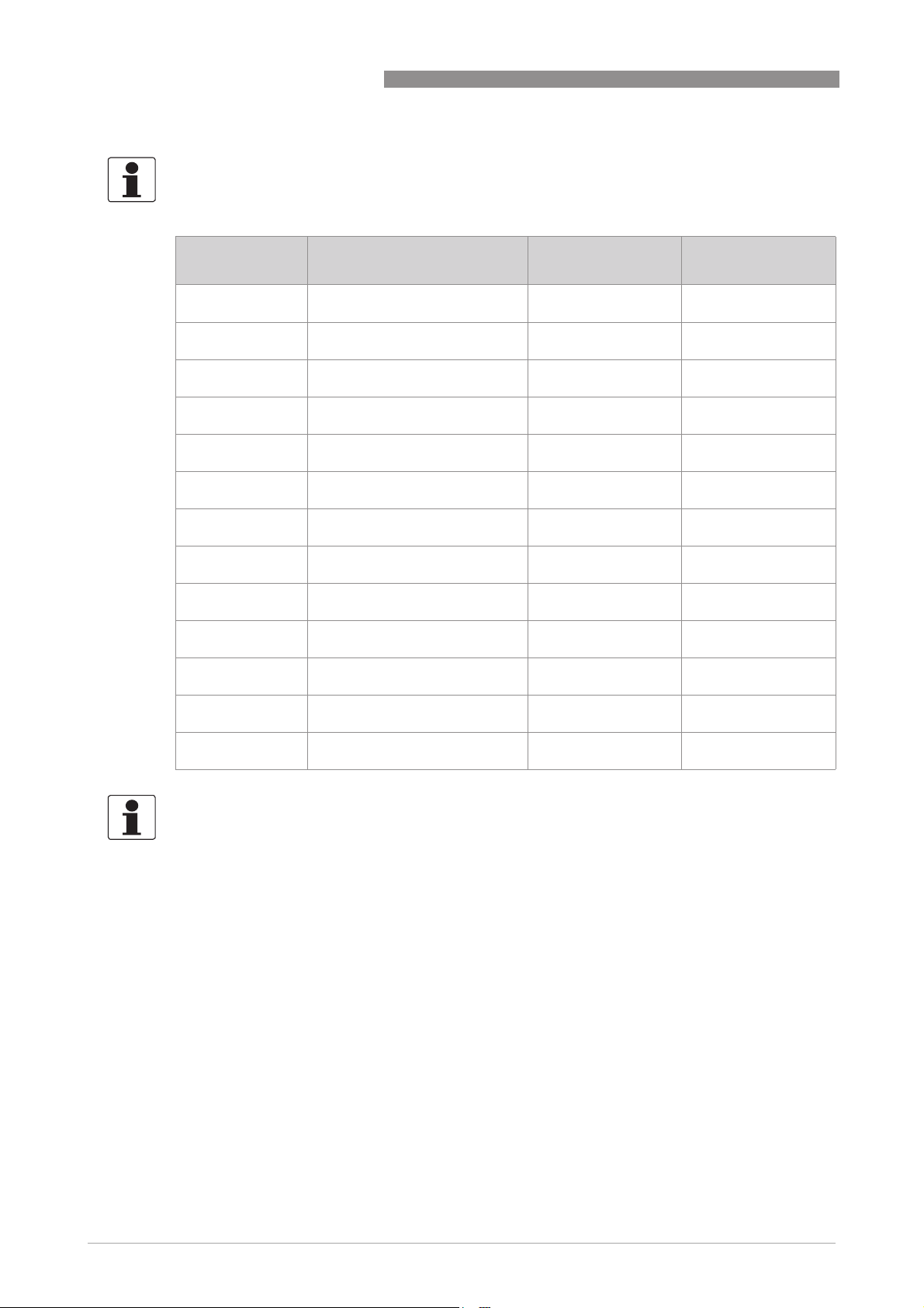
INFORMATION!
In the table below, "x" is a placeholder for possible multi-digit alphanumeric combinations,
depending on the available version.
IFC 300
Release date Electronic Revision Changes and
compatibility
2006-12-12 ER 3.1.0x
(SW.REV. 3.10 (2.21))
2007-02-07 ER 3.1.1x
(SW.REV. 3.10 (2.21))
2007-03-12 ER 3.1.2x
(SW.REV. 3.10 (2.21))
2007-05-25 ER 3.1.3x
(SW.REV. 3.10 (2.21))
2008-05-13 ER 3.2.0x
(SW.REV. 3.20 (3.00))
2008-07-25 ER 3.2.1x
(SW.REV. 3.20 (3.03))
2008-08-29 ER 3.2.2x
(SW.REV. 3.20 (3.03))
2008-10-30 ER 3.2.4x
(SW.REV. 3.20 (3.03))
2009-05-15 ER 3.2.5x
(SW.REV. 3.20 (3.03))
2009-12-07 ER 3.2.6x
(SW.REV. 3.20 (3.03))
2009-11-02 ER 3.2.7x
(SW.REV. 3.20 (3.03))
2009-12-07 ER 3.2.8x
(SW.REV. 3.20 (3.03))
2010 ER 3.3.0x
(SW.REV. 3.30 (3.04))
- -
1; 2 MA IFC 300 R02
1; 2-H; 3-I MA IFC 300 R02
1; 3-I MA IFC 300 R02
1; 2-X; 3-X; 4 MA IFC 300 R03
1 MA IFC 300 R03
1 MA IFC 300 R03
1 MA IFC 300 R03
2-F MA IFC 300 R03
1 MA IFC 300 R03
1 MA IFC 300 R03
1 MA IFC 300 R03
1; 2-H; 2-F; 3-X; 4 MA IFC 300 R04
Documentation
INFORMATION!
For the measuring sensors TIDALFLUX 4000 and OPTIFLUX 7000 the software version ER 3.3.0x
and higher (SW.REV. 3.30 (3.04)) is valid!
8
www.krohne.com 08/2010 - 4000069803 - MA IFC 300 R04 en
Page 9
IFC 300
1.2 Intended use
The electromagnetic flowmeters are designed exclusively to measure the flow and conductivity
of electrically conductive, liquid media.
DANGER!
For devices used in hazardous areas, additional safety notes apply; please refer to the Ex
documentation.
WARNING!
If the device is not used according to the operating conditions (refer to chapter "Technical data),
the intended protection could be affected.
1.3 Certifications
CE marking
SAFETY INSTRUCTIONS 1
The device fulfils the statutory requirements of the following EC directives:
• Low Voltage Directive 2006/95/EC
• EMC Directive 2004/108/EC
as well as
• EN 61010
• EMC specification acc. to EN 61326/A1
• NAMUR recommendations NE 21 and NE 43
The manufacturer certifies successful testing of the product by applying the CE marking.
DANGER!
For devices used in hazardous areas, additional safety notes apply; please refer to the Ex
documentation.
www.krohne.com08/2010 - 4000069803 - MA IFC 300 R04 en
9
Page 10

1 SAFETY INSTRUCTIONS
1.4 Safety instructions from the manufacturer
1.4.1 Copyright and data protection
The contents of this document have been created with great care. Nevertheless, we provide no
guarantee that the contents are correct, complete or up-to-date.
The contents and works in this document are subject to copyright. Contributions from third
parties are identified as such. Reproduction, processing, dissemination and any type of use
beyond what is permitted under copyright requires written authorisation from the respective
author and/or the manufacturer.
The manufacturer tries always to observe the copyrights of others, and to draw on works created
in-house or works in the public domain.
The collection of personal data (such as names, street addresses or e-mail addresses) in the
manufacturer's documents is always on a voluntary basis whenever possible. Whenever
feasible, it is always possible to make use of the offerings and services without providing any
personal data.
IFC 300
We draw your attention to the fact that data transmission over the Internet (e.g. when
communicating by e-mail) may involve gaps in security. It is not possible to protect such data
completely against access by third parties.
We hereby expressly prohibit the use of the contact data published as part of our duty to publish
an imprint for the purpose of sending us any advertising or informational materials that we have
not expressly requested.
1.4.2 Disclaimer
The manufacturer will not be liable for any damage of any kind by using its product, including,
but not limited to direct, indirect, incidental, punitive and consequential damages.
This disclaimer does not apply in case the manufacturer has acted on purpose or with gross
negligence. In the event any applicable law does not allow such limitations on implied warranties
or the exclusion of limitation of certain damages, you may, if such law applies to you, not be
subject to some or all of the above disclaimer, exclusions or limitations.
Any product purchased from the manufacturer is warranted in accordance with the relevant
product documentation and our Terms and Conditions of Sale.
The manufacturer reserves the right to alter the content of its documents, including this
disclaimer in any way, at any time, for any reason, without prior notification, and will not be liable
in any way for possible consequences of such changes.
10
www.krohne.com 08/2010 - 4000069803 - MA IFC 300 R04 en
Page 11

IFC 300
1.4.3 Product liability and warranty
The operator shall bear responsibility for the suitability of the device for the specific purpose.
The manufacturer accepts no liability for the consequences of misuse by the operator. Improper
installation and operation of the devices (systems) will cause the warranty to be void. The
respective "Standard Terms and Conditions" which form the basis for the sales contract shall
also apply.
1.4.4 Information concerning the documentation
To prevent any injury to the user or damage to the device it is essential that you read the
information in this document and observe applicable national standards, safety requirements
and accident prevention regulations.
If this document is not in your native language and if you have any problems understanding the
text, we advise you to contact your local office for assistance. The manufacturer can not accept
responsibility for any damage or injury caused by misunderstanding of the information in this
document.
This document is provided to help you establish operating conditions, which will permit safe and
efficient use of this device. Special considerations and precautions are also described in the
document, which appear in the form of underneath icons.
SAFETY INSTRUCTIONS 1
www.krohne.com08/2010 - 4000069803 - MA IFC 300 R04 en
11
Page 12
1 SAFETY INSTRUCTIONS
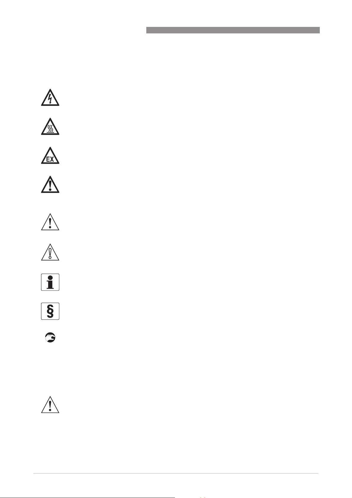
1.4.5 Warnings and symbols used
Safety warnings are indicated by the following symbols.
DANGER!
This information refers to the immediate danger when working with electricity.
DANGER!
This warning refers to the immediate danger of burns caused by heat or hot surfaces.
DANGER!
This warning refers to the immediate danger when using this device in a hazardous atmosphere.
DANGER!
These warnings must be observed without fail. Even partial disregard of this warning can lead to
serious health problems and even death. There is also the risk of seriously damaging the device
or parts of the operator's plant.
IFC 300
WARNING!
Disregarding this safety warning, even if only in part, poses the risk of serious health problems.
There is also the risk of damaging the device or parts of the operator's plant.
CAUTION!
Disregarding these instructions can result in damage to the device or to parts of the operator's
plant.
INFORMATION!
These instructions contain important information for the handling of the device.
LEGAL NOTICE!
This note contains information on statutory directives and standards.
• HANDLING
HANDLING
HANDLINGHANDLING
This symbol designates all instructions for actions to be carried out by the operator in the
specified sequence.
i RESULT
RESULT
RESULTRESULT
This symbol refers to all important consequences of the previous actions.
1.5 Safety instructions for the operator
12
WARNING!
In general, devices from the manufacturer may only be installed, commissioned, operated and
maintained by properly trained and authorized personnel.
This document is provided to help you establish operating conditions, which will permit safe and
efficient use of this device.
www.krohne.com 08/2010 - 4000069803 - MA IFC 300 R04 en
Page 13
IFC 300
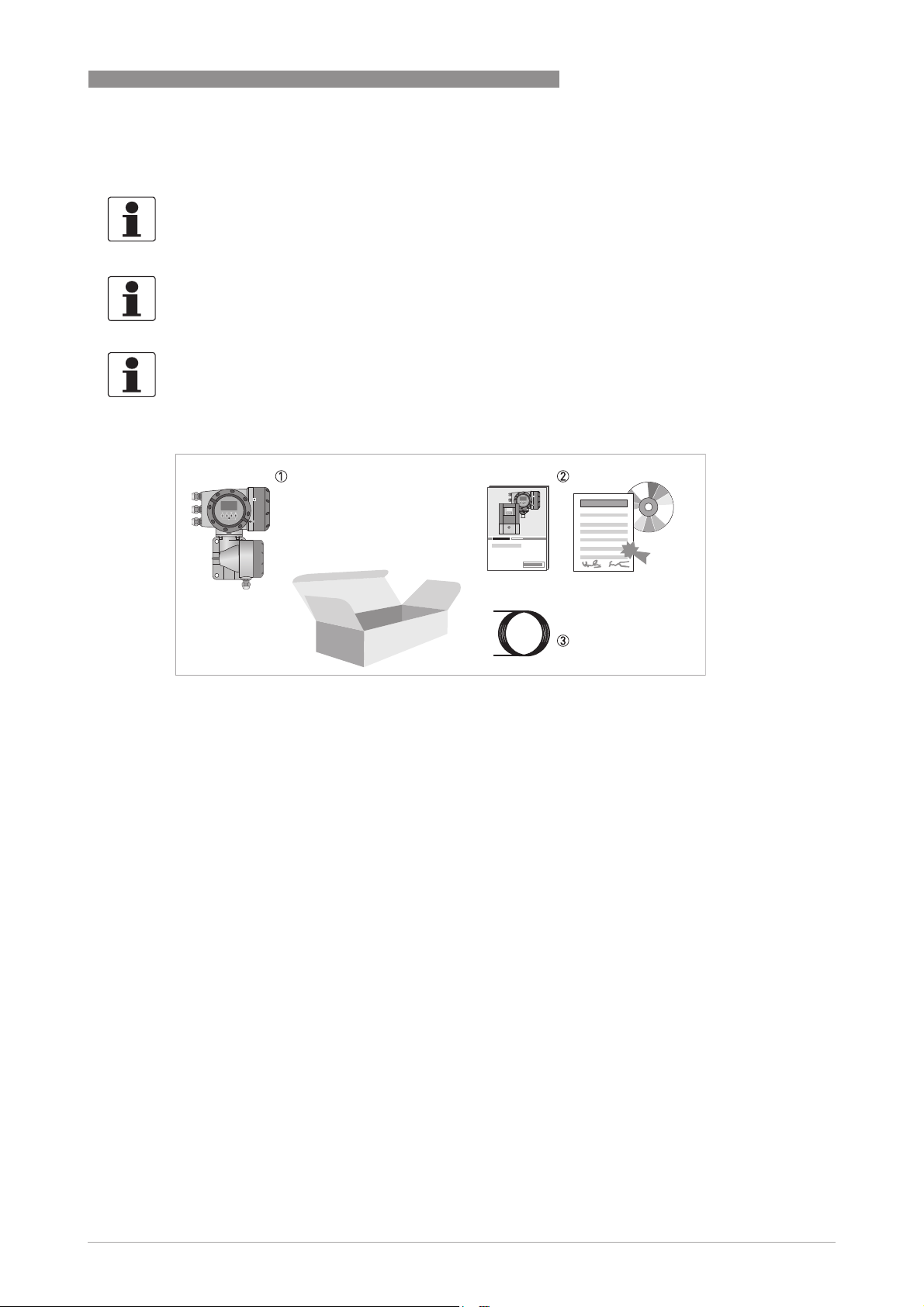
2.1 Scope of delivery
INFORMATION!
Inspect the cartons carefully for damage or signs of rough handling. Report damage to the
carrier and to the local office of the manufacturer.
INFORMATION!
Check the packing list to check if you received completely all that you ordered.
INFORMATION!
Look at the device nameplate to ensure that the device is delivered according to your order.
Check for the correct supply voltage printed on the nameplate.
DEVICE DESCRIPTION 2
Figure 2-1: Scope of delivery
1 Device in the version as ordered
2 Documentation (calibration report, Quick Start, CD-Rom with product documentation for measuring sensor and signal
converter)
3 Signal cable (only for remote version)
www.krohne.com08/2010 - 4000069803 - MA IFC 300 R04 en
13
Page 14
2 DEVICE DESCRIPTION
Possible scope of delivery for signal converter / measuring sensor
Measuring sensor Measuring sensor + signal converter IFC 300
IFC 300
Compact Remote field
housing
Remote wallmounted housing
Remote rack-mounted
housing
R (28 TE) or (21 TE)
OPTIFLUX 1000 OPTIFLUX 1300 C OPTIFLUX 1300 F OPTIFLUX 1300 W OPTIFLUX 1300 R
OPTIFLUX 2000 OPTIFLUX 2300 C OPTIFLUX 2300 F OPTIFLUX 2300 W OPTIFLUX 2300 R
OPTIFLUX 4000 OPTIFLUX 4300 C OPTIFLUX 4300 F OPTIFLUX 4300 W OPTIFLUX 4300 R
OPTIFLUX 5000 OPTIFLUX 5300 C OPTIFLUX 5300 F OPTIFLUX 5300 W OPTIFLUX 5300 R
OPTIFLUX 6000 OPTIFLUX 6300 C OPTIFLUX 6300 F OPTIFLUX 6300 W OPTIFLUX 6300 R
OPTIFLUX 7000 OPTIFLUX 7300 C - - -
WATERFLUX 3000 WATERFLUX 3300 C WATERFLUX 3300 F WATERFLUX 3300 W WATERFLUX 3300 R
TIDALFLUX 4000 - TIDALFLUX 4300 F - -
14
www.krohne.com 08/2010 - 4000069803 - MA IFC 300 R04 en
Page 15
IFC 300
2.2 Device description
Electromagnetic flowmeters are designed exclusively to measure the flow and conductivity of
electrically conductive, liquid media.
Your measuring device is supplied ready for operation. The factory settings for the operating
data have been made in accordance with your order specifications.
The following versions are available:
• Compact version (the signal converter is mounted directly on the measuring sensor)
• Remote version (electrical connection to the measuring sensor via field current and signal
cable)
DEVICE DESCRIPTION 2
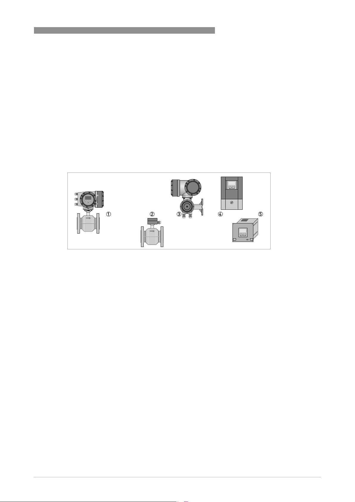
Figure 2-2: Device versions
1 Compact version
2 Measuring sensor with connection box
3 Field housing
4 Wall-mounted housing
5 19" rack-mounted housing
www.krohne.com08/2010 - 4000069803 - MA IFC 300 R04 en
15
Page 16
2 DEVICE DESCRIPTION
2.2.1 Field housing
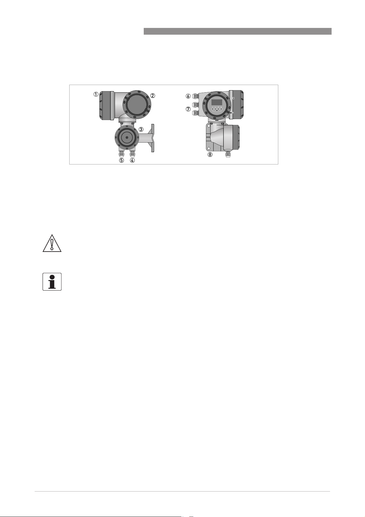
Figure 2-3: Construction of the field housing
1 Cover for electronics and display
2 Cover for power supply and inputs/outputs terminal compartment
3 Cover for for measuring sensor terminal compartment with locking screw
4 Cable entry for measuring sensor signal cable
5 Cable entry for measuring sensor field current cable
6 Cable entry for power supply
7 Cable entry for inputs and outputs
8 Mounting plate for pipe and wall mounting
IFC 300
CAUTION!
The design of the TIDALFLUX field housing is different to the standard version shown here. There
is an additional bush for the interface cable. For detailed information refer to Connection of
cables on page 63
.
INFORMATION!
Each time a housing cover is opened, the thread should be cleaned and greased. Use only resinfree and acid-free grease.
Ensure that the housing gasket is properly fitted, clean and undamaged.
16
www.krohne.com 08/2010 - 4000069803 - MA IFC 300 R04 en
Page 17
IFC 300
2.2.2 Wall-mounted housing
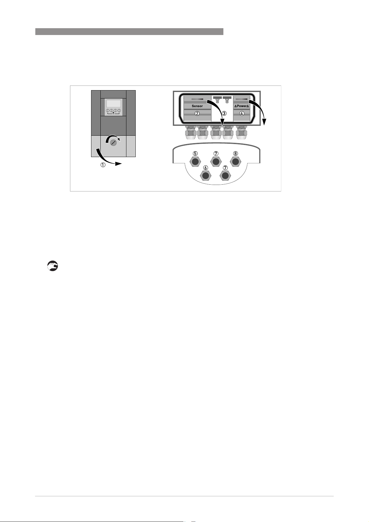
Figure 2-4: Construction of wall-mounted housing
1 Cover for terminal compartments
2 Terminal compartment for measuring sensor
3 Terminal compartment for inputs and outputs
4 Terminal compartment for power supply with safety cover (shock-hazard protection)
5 Cable entry for signal cable
6 Cable entry for field current cable
7 Cable entry for inputs and outputs
8 Cable entry for power supply
DEVICE DESCRIPTION 2
1 Turn lock to the right and open the cover.
www.krohne.com08/2010 - 4000069803 - MA IFC 300 R04 en
17
Page 18
2 DEVICE DESCRIPTION
2.3 Nameplates
INFORMATION!
Look at the device nameplate to ensure that the device is delivered according to your order.
Check for the correct supply voltage printed on the nameplate.
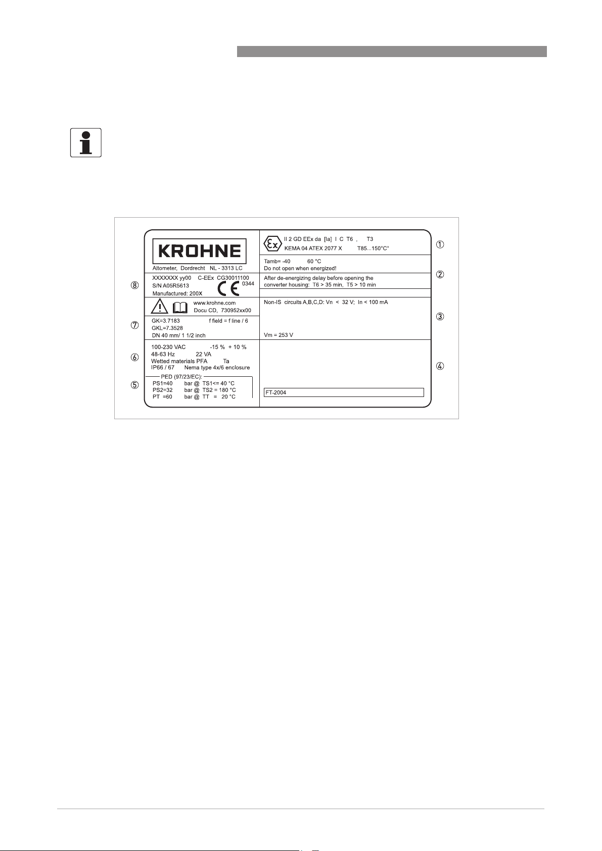
2.3.1 Compact version (example)
IFC 300
Figure 2-5: Example of a nameplate for compact version
1 Approvals-related information: Ex approval, EC type test certificate, hygienic approvals, etc.
2 Approvals-related thresholds
3 Approvals-related connection data of the inputs/outputs; V
4 Approvals-related data (e.g. accuracy class, measuring range, temperature thresholds, pressure thresholds and vis-
cosity thresholds)
5 Approvals-related pressure and temperature thresholds
6 Power supply; protection category; materials of wetted parts
7 GK/GKL values (measuring sensor constants); size (mm /inches); field frequency
8 Product designation, serial number and manufacturing date
= max. power supply
m
18
www.krohne.com 08/2010 - 4000069803 - MA IFC 300 R04 en
Page 19
IFC 300
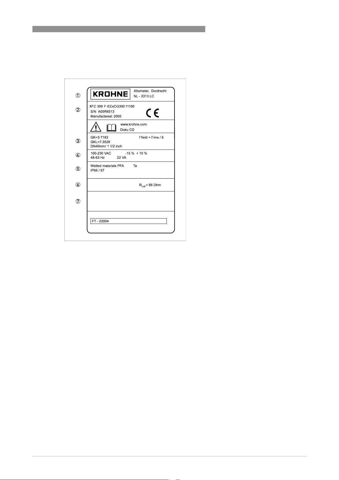
2.3.2 Remote version (example)
DEVICE DESCRIPTION 2
Figure 2-6: Example of a nameplate for remote version
1 Manufacturer
2 Product designation, serial number and manufacturing date
3 GK/GKL values (measuring sensor constants); size (mm /inches); field frequency
4 Power supply
5 Materials of wetted parts
6 Field coil resistance
7 Approvals-related data (e.g. accuracy class, measuring range, temperature thresholds, pressure thresholds and vis-
cosity thresholds)
www.krohne.com08/2010 - 4000069803 - MA IFC 300 R04 en
19
Page 20
2 DEVICE DESCRIPTION
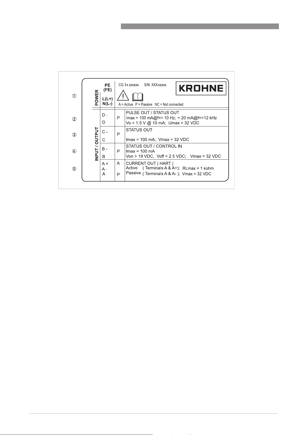
2.3.3 Electrical connection data of inputs/outputs (example of basic version)
IFC 300
Figure 2-7: Example of a nameplate for electrical connection data of inputs and outputs
1 Power supply (AC: L and N; DC: L+ and L-; PE for ≥ 24 VAC; FE for ≤ 24 VAC and DC)
2 Connection data of connection terminal D/D-
3 Connection data of connection terminal C/C-
4 Connection data of connection terminal B/B-
5 Connection data of connection terminal A/A-; A+ only operable in the basic version
• A = active mode; the signal converter supplies the power for connection of the subsequent
devices
• P = passive mode; external power supply required for operation of the subsequent devices
• N/C = connection terminals not connected
20
www.krohne.com 08/2010 - 4000069803 - MA IFC 300 R04 en
Page 21

IFC 300
3.1 Notes on installation
INFORMATION!
Inspect the cartons carefully for damage or signs of rough handling. Report damage to the
carrier and to the local office of the manufacturer.
INFORMATION!
Check the packing list to check if you received completely all that you ordered.
INFORMATION!
Look at the device nameplate to ensure that the device is delivered according to your order.
Check for the correct supply voltage printed on the nameplate.
3.2 Storage
• Store the device in a dry, dust-free location.
• Avoid continuous direct sunlight.
• Store the device in its original packing.
• Storage temperature: -50...+70°C / -58...+158°F
INSTALLATION 3
3.3 Transport
Signal converter
• No special requirements.
Compact version
• Do not lift the device by the signal converter housing.
• Do not use lifting chains.
• To transport flange devices, use lifting straps. Wrap these around both process connections.
3.4 Installation specifications
INFORMATION!
The following precautions must be taken to ensure reliable installation.
•
Make sure that there is adequate space to the sides.
•
Protect the signal converter from direct sunlight and install a sun shade if necessary.
•
Signal converters installed in control cabinets require adequate cooling, e.g. by fan or heat
exchanger.
•
Do not expose the signal converter to intense vibration. The flowmeters are tested for a
vibration level in accordance with IEC 68-2-3.
www.krohne.com08/2010 - 4000069803 - MA IFC 300 R04 en
21
Page 22
3 INSTALLATION
3.5 Mounting of the compact version
INFORMATION!
The signal converter is mounted directly on the measuring sensor. For installation of the
flowmeter, please observe the instructions in the supplied product documentation for the
measuring sensor.
3.6 Mounting the field housing, remote version
INFORMATION!
Assembly materials and tools are not part of the delivery. Use the assembly materials and tools
in compliance with the applicable occupational health and safety directives.
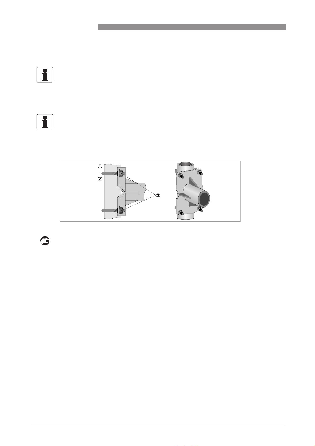
3.6.1 Pipe mounting
IFC 300
Figure 3-1: Pipe mounting of the field housing
1 Fix the signal converter to the pipe.
2 Fasten the signal converter using standard U-bolts and washers.
3 Tighten the nuts.
22
www.krohne.com 08/2010 - 4000069803 - MA IFC 300 R04 en
Page 23
IFC 300
3.6.2 Wall mounting
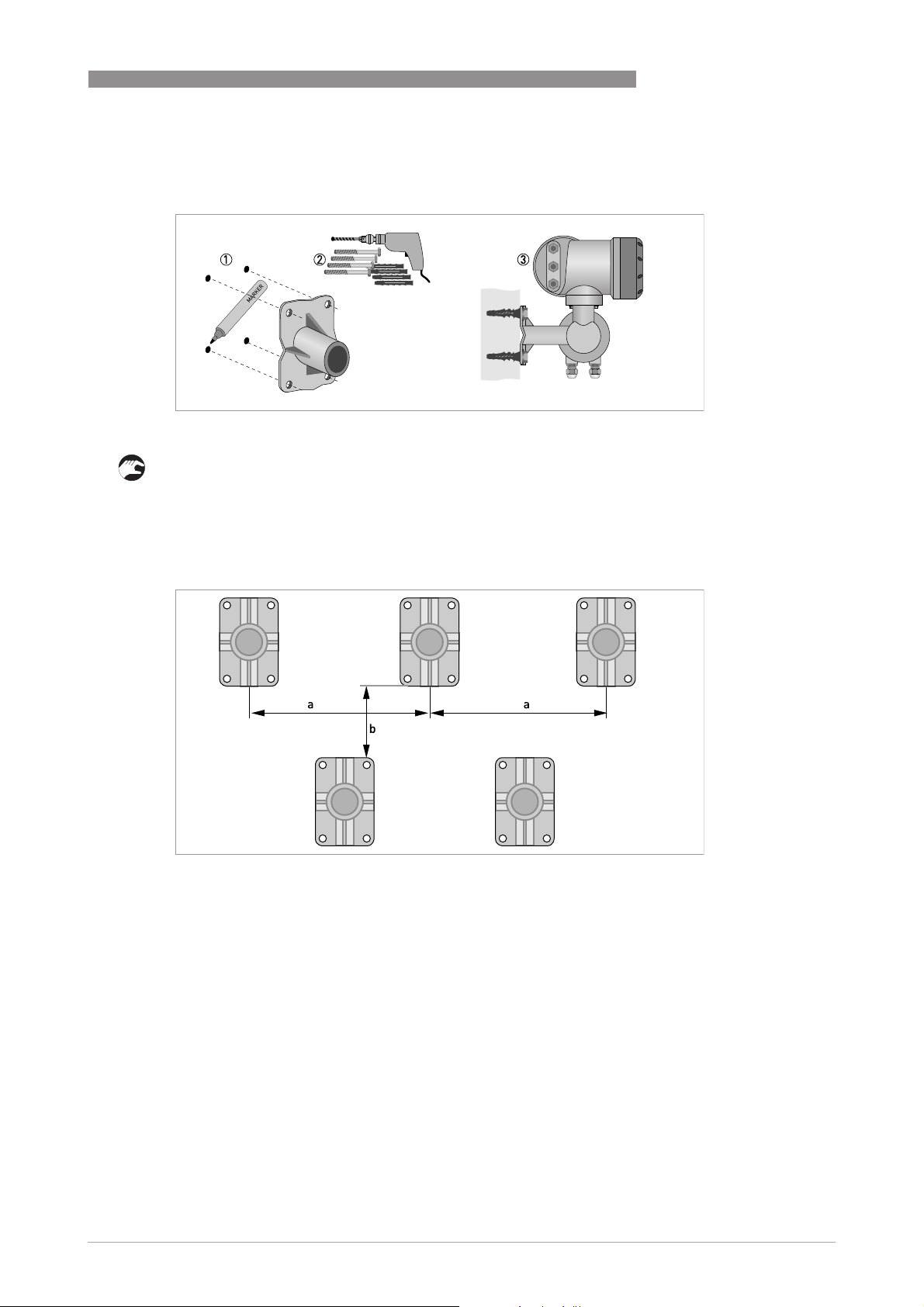
Figure 3-2: Wall mounting of the field housing
INSTALLATION 3
1 Prepare the holes with the aid of the mounting plate. For further information refer to
plate, field housing
on page 157.
Mounting
2 Use the mounting material and tools in compliance with the applicable occupational health
and safety directives.
3 Fasten the housing securely to the wall.
Mounting multiple devices next to each other
a ≥ 600 mm / 23.6"
b ≥ 250 mm / 9.8"
www.krohne.com08/2010 - 4000069803 - MA IFC 300 R04 en
23
Page 24
3 INSTALLATION
3.6.3 Turning the display of the field housing version
IFC 300
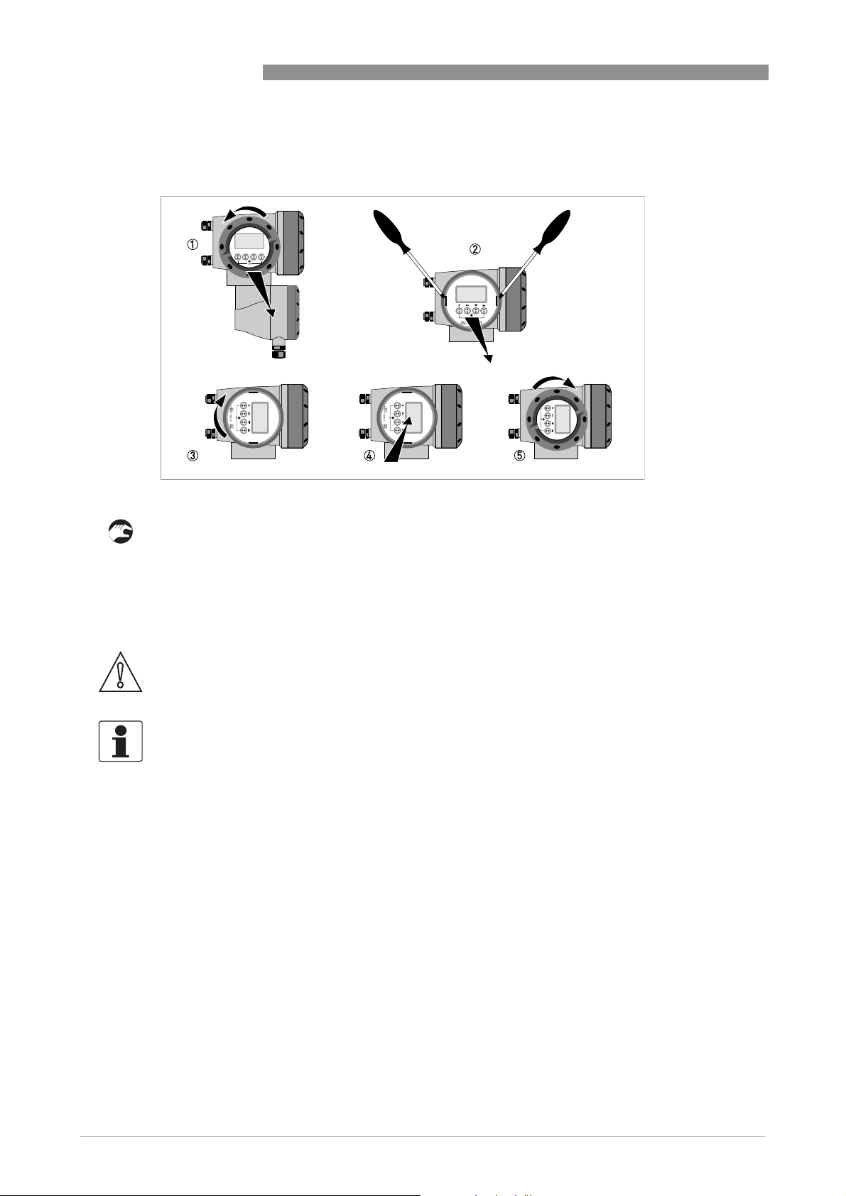
Figure 3-3: Turning the display of the field housing version
The display of the field housing version can be turned in 90° increments.
1 Unscrew the cover from the display and operation control unit.
2 Using a suitable tool, pull out the two metal puller devices to the left and right of the display.
3 Pull out the display between the two metal puller devices and rotate it to the required position.
4 Slide the display and then the metal puller devices back into the housing.
5 Re-fit the cover and tighten it by hand.
CAUTION!
The ribbon cable of the display must not be folded or twisted repeatedly.
INFORMATION!
Each time a housing cover is opened, the thread should be cleaned and greased. Use only resinfree and acid-free grease.
Ensure that the housing gasket is properly fitted, clean and undamaged.
24
www.krohne.com 08/2010 - 4000069803 - MA IFC 300 R04 en
Page 25
IFC 300
3.7 Mounting the wall-mounted housing, remote version
INFORMATION!
Assembly materials and tools are not part of the delivery. Use the assembly materials and tools
in compliance with the applicable occupational health and safety directives.
3.7.1 Pipe mounting
INSTALLATION 3
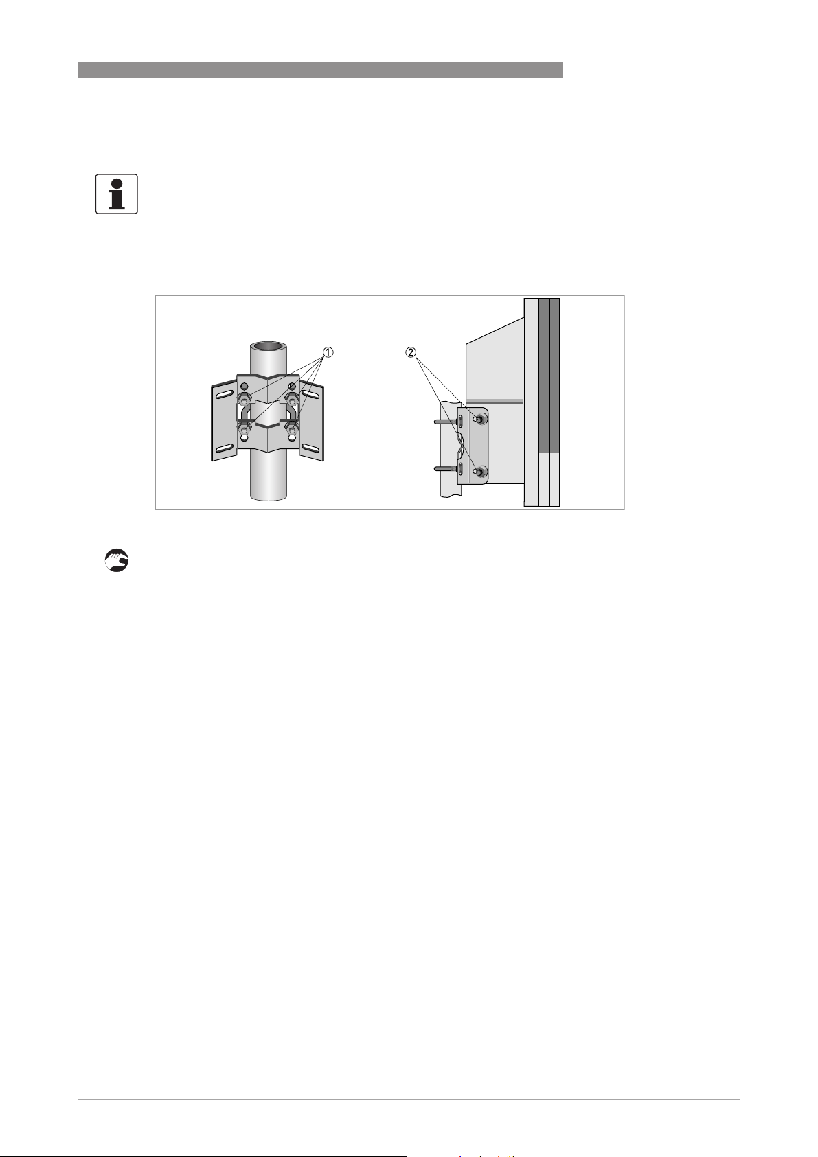
Figure 3-4: Pipe mounting of the wall-mounted housing
1 Fasten the mounting plate to the pipe with standard U-bolts, washers and fastening nuts.
2 Screw the signal converter to the mounting plate with the nuts and washers.
www.krohne.com08/2010 - 4000069803 - MA IFC 300 R04 en
25
Page 26
3 INSTALLATION
3.7.2 Wall mounting
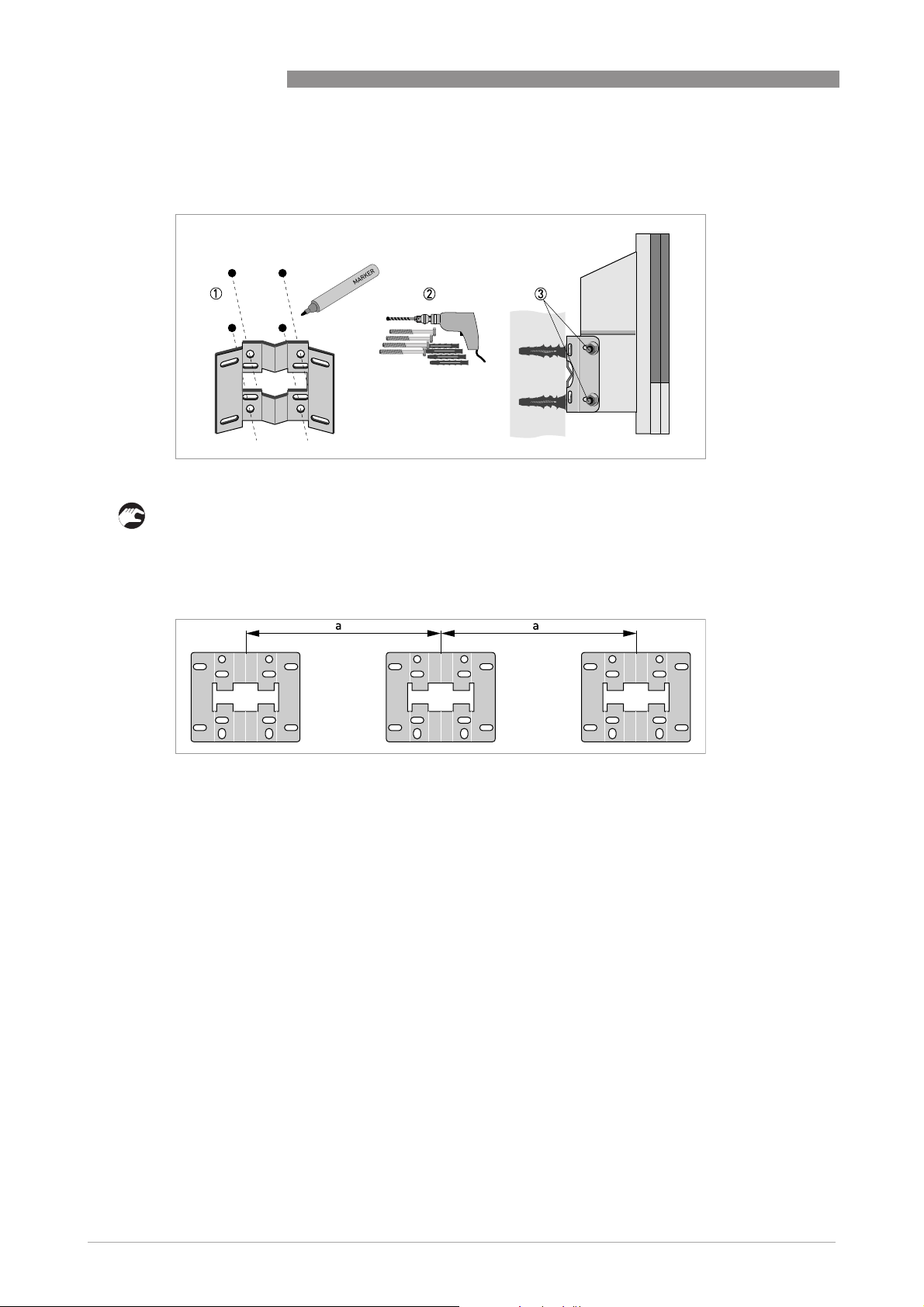
Figure 3-5: Wall mounting of the wall-mounted housing
IFC 300
1 Prepare the holes with the aid of the mounting plate. For further information refer to
plate, wall-mounted housing
on page 157.
2 Fasten the mounting plate securely to the wall.
3 Screw the signal converter to the mounting plate with the nuts and washers.
Mounting multiple devices next to each other
a ≥ 240 mm / 9.4"
Mounting
26
www.krohne.com 08/2010 - 4000069803 - MA IFC 300 R04 en
Page 27
IFC 300
4.1 Safety instructions
DANGER!
All work on the electrical connections may only be carried out with the power disconnected. Take
note of the voltage data on the nameplate!
DANGER!
Observe the national regulations for electrical installations!
DANGER!
For devices used in hazardous areas, additional safety notes apply; please refer to the Ex
documentation.
WARNING!
Observe without fail the local occupational health and safety regulations. Any work done on the
electrical components of the measuring device may only be carried out by properly trained
specialists.
ELECTRICAL CONNECTIONS 4
INFORMATION!
Look at the device nameplate to ensure that the device is delivered according to your order.
Check for the correct supply voltage printed on the nameplate.
4.2 Important notes on electrical connection
DANGER!
Electrical connection is carried out in conformity with the VDE 0100 directive "Regulations for
electrical power installations with line voltages up to 1000 V" or equivalent national regulations.
CAUTION!
•
Use suitable cable entries for the various electrical cables.
•
The sensor and converter are configured together in the factory. For this reason, please
connect the devices in pairs. Ensure that the sensor constant GK/GKL (see type plates) are
identically set.
•
If delivered separately or when installing devices that were not configured together, set the
converter to the DN size and GK/GKL of the sensor, refer to Function tables on page 111
.
www.krohne.com08/2010 - 4000069803 - MA IFC 300 R04 en
27
Page 28
4 ELECTRICAL CONNECTIONS
4.3 Electrical cables for remote device versions, notes
4.3.1 Notes on signal cables A and B
INFORMATION!
The signal cables A (type DS 300) with double shield and B (type BTS 300) with triple shield
ensure proper transmission of measured values.
Observe the following notes:
• Lay the signal cable with fastening elements.
• It is permissible to lay the signal cable in water or in the ground.
• The insulating material is flame-retardant to EN 50625-2-1, IEC 60322-1.
• The signal cable does not contain any halogens and is unplasticized, and remains flexible at
low temperatures.
• The connection of the inner shield is carried out via the stranded drain wire (1).
• The connection of the outer shield is carried out via the shield (60) or the stranded drain wire
(6), depending on the housing version. Observe the following notes.
• The signal cable type B cannot be used with options with "virtual reference"!
IFC 300
4.3.2 Notes on field current cable C
DANGER!
All versions except TIDALFLUX:
All versions except TIDALFLUX:
All versions except TIDALFLUX:All versions except TIDALFLUX:
A non-shielded three-wire copper cable is sufficient for the field current cable. If you
nevertheless use shielded cables, the shield must NOT
converter.
Only TIDALFLUX:
Only TIDALFLUX:
Only TIDALFLUX:Only TIDALFLUX:
A shielded two-wire copper cable is used as the field current cable. The shielding MUST
connected in the housing of the measuring sensor and signal converter.
INFORMATION!
The field current cable is not part of the scope of delivery.
NOT be connected in the housing of the signal
NOTNOT
MUST be
MUSTMUST
28
www.krohne.com 08/2010 - 4000069803 - MA IFC 300 R04 en
Page 29

IFC 300
ELECTRICAL CONNECTIONS 4
4.3.3 Requirements for signal cables provided by the customer
INFORMATION!
If the signal cable was not ordered, it is to be provided by the customer. The following
requirements regarding the electrical values of the signal cable must be observed:
Electrical safety
• To EN 60811 (Low Voltage Directive) or equivalent national regulations.
Capacitance of the insulated conductors
• Insulated conductor / insulated conductor < 50 pF/m
• Insulated conductor / shield < 150 pF/m
Insulation resistance
• R
• U
• I
> 100 GΩ xkm
iso
< 24 V
max
< 100 mA
max
Test voltages
• Insulated conductor / inner shield 500 V
• Insulated conductor / insulated conductor 1000 V
• Insulated conductor / outer shield 1000 V
Twisting of the insulated conductors
• At least 10 twists per meter, important for screening magnetic fields.
www.krohne.com08/2010 - 4000069803 - MA IFC 300 R04 en
29
Page 30
4 ELECTRICAL CONNECTIONS
4.4 Preparing the signal and field current cables (except TIDALFLUX)
INFORMATION!
Assembly materials and tools are not part of the delivery. Use the assembly materials and tools
in compliance with the applicable occupational health and safety directives.
The electrical connection of the outer shield is different for the various housing variants. Please
observe the corresponding instructions.
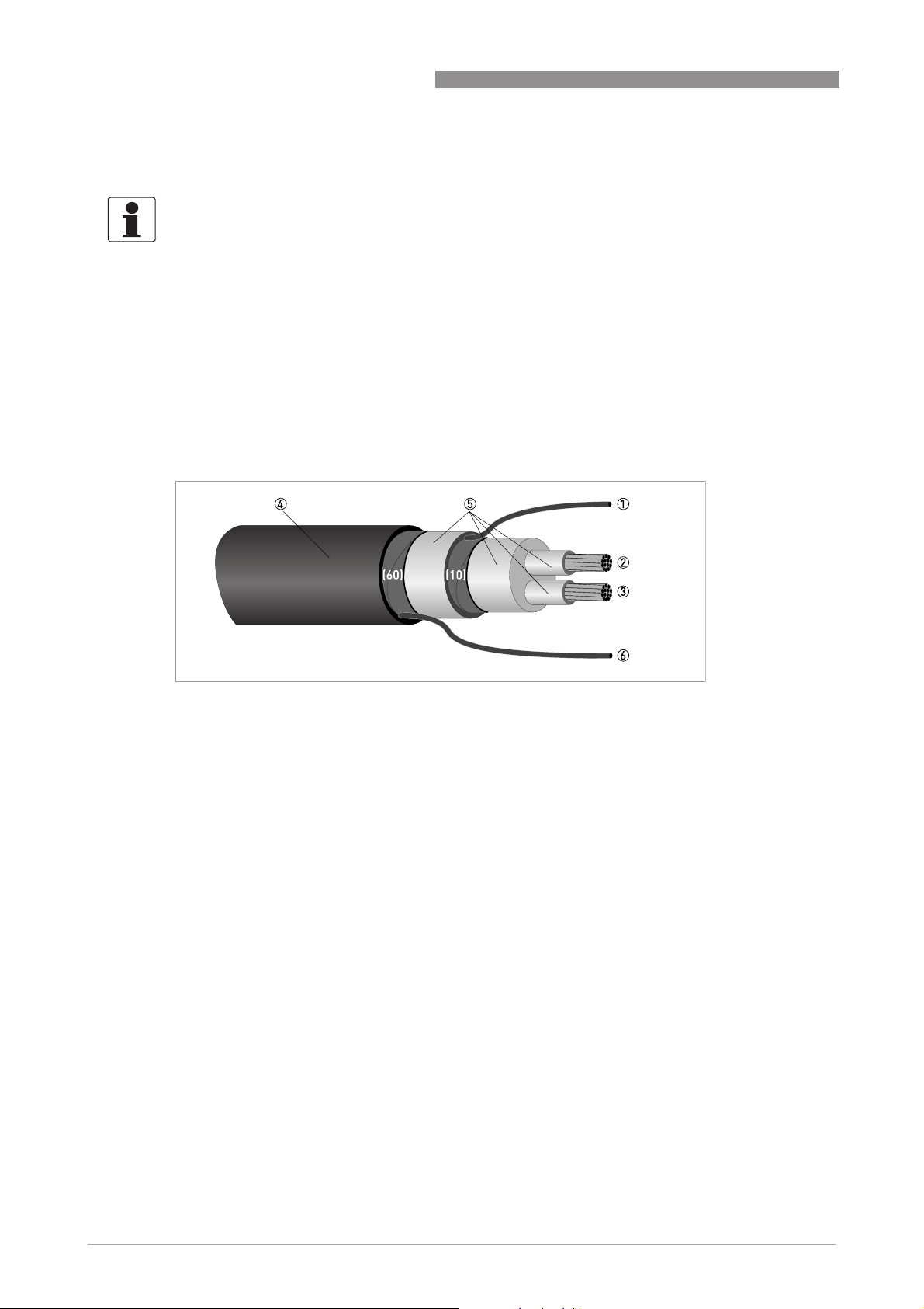
4.4.1 Signal cable A (type DS 300), construction
• Signal cable A is a double-shielded cable for signal transmission between the measuring
sensor and signal converter.
• Bending radius: ≥ 50 mm / 2"
IFC 300
Figure 4-1: Construction of signal cable A
1 Stranded drain wire (1) for the inner shield (10), 1.0 mm
2 Insulated wire (2), 0.5 mm
3 Insulated wire (3), 0.5 mm
4 Outer sheath
5 Insulation layers
6 Stranded drain wire (6) for the outer shield (60)
2
Cu / AWG 20
2
Cu / AWG 20
2
Cu / AWG 17 (not insulated, bare)
30
www.krohne.com 08/2010 - 4000069803 - MA IFC 300 R04 en
Page 31

IFC 300
ELECTRICAL CONNECTIONS 4
4.4.2 Preparing signal cable A, connection to signal converter
Field housing
INFORMATION!
Assembly materials and tools are not part of the delivery. Use the assembly materials and tools
in compliance with the applicable occupational health and safety directives.
• The outside shield (60) is connected in the field housing directly via the shield and a clip.
• Bending radius: ≥ 50 mm / 2"
Required materials:
• PVC insulation tubing, Ø2.5 mm / 0.1"
• Heat-shrinkable tubing
• Wire end ferrule to DIN 46 228: E 1.5-8 for the stranded drain wire (1)
• 2x wire end ferrules to DIN 46 228: E 0.5-8 for the insulated conductors (2, 3)
Figure 4-2: Signal cable A, preparation for field housing
a = 80 mm / 3.15"
b = 10 mm / 0.39"
1 Strip the conductor to dimension a.
Trim the outer shield to dimension b and pull it over the outer sheath.
2 Cut off the inner shield (10) and the stranded drain wire (6). Make sure not to damage the
stranded drain wire (1).
3 Slide an insulating tube over the stranded drain wire (1).
4 Crimp the wire end ferrules onto the conductors (2, 3) and stranded drain wire.
5 Pull the heat-shrinkable tubing over the prepared signal cable.
www.krohne.com08/2010 - 4000069803 - MA IFC 300 R04 en
31
Page 32

4 ELECTRICAL CONNECTIONS
Wall mounted housing
INFORMATION!
Assembly materials and tools are not part of the delivery. Use the assembly materials and tools
in compliance with the applicable occupational health and safety directives.
• The connection of the outer shield (60) is carried out in the wall-mounted housing via the
stranded drain wire (6).
• Bending radius: ≥ 50 mm / 2"
Required materials
• Push-on connector 6.3 mm / 0.25", insulation to DIN 46245 for conductor Ø = 0.5...1 mm2 /
AWG 20...17
• PVC insulation tubing, Ø2.5 mm / 0.1"
• Heat-shrinkable tubing
• Wire end ferrule to DIN 46 228: E 1.5-8 for the stranded drain wire (1)
• 2x wire end ferrules to DIN 46 228: E 0.5-8 for the insulated conductors (2, 3)
IFC 300
32
Figure 4-3: Signal cable A, preparation for wall-mounted housing
a = 80 mm / 3.15"
1 Strip the conductor to dimension a.
2 Cut off the inner shield (10) and the outer shield (60). Make sure not to damage the stranded
drain wires (1) and (6).
3 Slide the insulation tubing over the stranded drain wires.
4 Crimp the push-on connector onto the stranded drain wire (6).
5 Crimp the wire end ferrules onto the conductors (2, 3) and stranded drain wire (1).
6 Pull the heat-shrinkable tubing over the prepared signal cable.
www.krohne.com 08/2010 - 4000069803 - MA IFC 300 R04 en
Page 33

IFC 300
4.4.3 Length of signal cable A
INFORMATION!
For temperatures of the medium above 150
intermediate socket are necessary. These are available including the changed electrical
connection diagrams.
ELECTRICAL CONNECTIONS 4
°
C / 300°F, a special signal cable and a ZD
Measuring sensor Nominal size Min. electrical
conductivity
DN [mm] [inch]
OPTIFLUX 1000 F 10...150 3/8...6 5 A1
OPTIFLUX 2000 F 25...150 1...6 20 A1
200...2000 8...80 20 A2
OPTIFLUX 4000 F 2.5...150 1/10...6 1 A1
200...2000 8...80 1 A2
OPTIFLUX 5000 F 2.5...100 1/10...4 1 A1
150...250 6...10 1 A2
OPTIFLUX 6000 F 2.5...150 1/10...6 1 A1
WATERFLUX 3000 F 25...600 1...24 20 A1
[µS/cm]
Curve for signal
cable A
Figure 4-4: Maximum length of signal cable A
1 Maximum length of signal cable A between the measuring sensor and signal converter [m]
2 Maximum length of signal cable A between the measuring sensor and signal converter [ft]
3 Electrical conductivity of the medium being measured [μS/cm]
www.krohne.com08/2010 - 4000069803 - MA IFC 300 R04 en
33
Page 34

4 ELECTRICAL CONNECTIONS
4.4.4 Signal cable B (type BTS 300), construction
• Signal cable B is a triple-shielded cable for signal transmission between the measuring
sensor and signal converter.
• Bending radius: ≥ 50 mm / 2"
Figure 4-5: Construction of signal cable B
1 Stranded drain wire for the inner shield (10), 1.0 mm
2 Insulated wire (2), 0.5 mm
3 Insulated wire (3), 0.5 mm
4 Outer sheath
5 Insulation layers
6 Stranded drain wire (6) for the outer shield (60), 0.5 mm
2
Cu / AWG 20 with stranded drain wire (20) of shield
2
Cu / AWG 20 with stranded drain wire (30) of shield
2
Cu / AWG 17 (not insulated, bare)
2
Cu / AWG 20 (not insulated, bare)
IFC 300
4.4.5 Preparing signal cable B, connection to signal converter
Field housing
INFORMATION!
Assembly materials and tools are not part of the delivery. Use the assembly materials and tools
in compliance with the applicable occupational health and safety directives.
• The outside shield (60) is connected in the field housing directly via the shield and a clip.
• Bending radius: ≥ 50 mm / 2"
Required materials
• PVC insulation tubing, Ø2.0...2.5 mm / 0.08...0.1"
• Heat-shrinkable tubing
• Wire end ferrule to DIN 46 228: E 1.5-8 for the stranded drain wire (1)
• 4 wire end ferrules to DIN 46 228: E 0.5-8 for the insulated conductors 2 and 3 and the
stranded drain wires (20, 30)
34
www.krohne.com 08/2010 - 4000069803 - MA IFC 300 R04 en
Page 35

IFC 300
ELECTRICAL CONNECTIONS 4
Figure 4-6: Signal cable B, preparation for field housing
a = 80 mm / 3.15"
b = 10 mm / 0.39"
1 Strip the conductor to dimension a.
2 Trim the outer shield to dimension b and pull it over the outer sheath.
3 Cut off the inner shield (10), the stranded drain wire (6) and the shields of the insulated con-
ductors. Make sure not to damage the stranded drain wires (1, 20, 30).
4 Slide the insulation tubing over the stranded drain wires (1, 20, 30).
5 Crimp the wire end ferrules onto the conductors and stranded drain wires.
6 Pull the heat-shrinkable tubing over the prepared signal cable.
www.krohne.com08/2010 - 4000069803 - MA IFC 300 R04 en
35
Page 36

4 ELECTRICAL CONNECTIONS
Wall-mounted housing
INFORMATION!
Assembly materials and tools are not part of the delivery. Use the assembly materials and tools
in compliance with the applicable occupational health and safety directives.
• The connection of the outer shield (60) is carried out in the wall-mounted housing via the
stranded drain wire (6).
• Bending radius: ≥ 50 mm / 2"
Required materials:
• Push-on connector 6.3 mm / 0.25", insulation to DIN 46245 for conductor Ø = 0.5...1 mm2 /
AWG 20...17
• PVC insulation tubing, Ø2.5 mm / 0.1"
• Heat-shrinkable tubing
• Wire end ferrule to DIN 46 228: E 1.5-8 for the stranded drain wire (1)
• 4 wire end ferrules to DIN 46 228: E 0.5-8 for insulated conductors 2 and 3 and the stranded
drain wires (20, 30)
IFC 300
36
Figure 4-7: Signal cable B, preparation for wall-mounted housing
a = 80 mm / 3.15"
1 Strip the conductor to dimension a.
2 Cut off the inner shield (10), the outer shield (60) and the shields for the conductor (2, 3). Make
sure not to damage the stranded drain wires (1, 6, 20, 30).
3 Slide the insulation tubing over the stranded drain wires.
4 Crimp the push-on connector onto the stranded drain wire (6).
5 Crimp the wire end ferrules onto the conductors and stranded drain wires (1, 20, 30).
6 Pull the heat-shrinkable tubing over the prepared signal cable.
www.krohne.com 08/2010 - 4000069803 - MA IFC 300 R04 en
Page 37

IFC 300
4.4.6 Length of signal cable B
INFORMATION!
For temperatures of the medium above 150
intermediate socket are necessary. These are available including the changed electrical
connection diagrams.
ELECTRICAL CONNECTIONS 4
°
C / 300°F, a special signal cable and a ZD
Measuring sensor Nominal size Min. electrical
conductivity
DN [mm] [inch]
OPTIFLUX 1000 F 10...150 3/8...6 5 B2
OPTIFLUX 2000 F 25...150 1...6 20 B3
200...2000 8...80 20 B4
OPTIFLUX 4000 F 2.5...6 1/10...1/6 10 B1
10...150 3/8...6 1 B3
200...2000 8...80 1 B4
OPTIFLUX 5000 F 2.5 1/10 10 B1
4...15 1/6...1/2 5 B2
25...100 1...4 1 B3
150...250 6...10 1 B4
OPTIFLUX 6000 F 2.5...15 1/10...1/2 10 B1
25...150 1...6 1 B3
WATERFLUX 3000 F 25...600 1...24 20 B1
[µS/cm]
Curve for signal
cable B
Figure 4-8: Maximum length of signal cable B
1 Maximum length of signal cable B between the measuring sensor and signal converter [m]
2 Maximum length of signal cable B between the measuring sensor and signal converter [ft]
3 Electrical conductivity of the medium being measured [μS/cm]
www.krohne.com08/2010 - 4000069803 - MA IFC 300 R04 en
37
Page 38

4 ELECTRICAL CONNECTIONS
4.4.7 Preparing field current cable C, connection to signal converter
DANGER!
A non-shielded three-wire copper cable is sufficient for the field current cable. If you
nevertheless use shielded cables, the shield must NOT
converter.
INFORMATION!
Assembly materials and tools are not part of the delivery. Use the assembly materials and tools
in compliance with the applicable occupational health and safety directives.
• Field current cable C is not part of the scope of delivery.
• Bending radius: ≥ 50 mm / 2"
Required materials:
• Shielded 3-wire copper cable with suitable heat-shrinkable tubing
• DIN 46 228 wire end ferrules: size according to the cable being used
NOT be connected in the housing of the signal
NOTNOT
IFC 300
Length and cross-section of field current cable C
Length Cross-section AF (Cu)
[m] [ft]
0...150 0...492 3 x 0.75 Cu 1 3 x 18
150...300 492...984 3 x 1.50 Cu 1 3 x 14
300...600 984...1968 3 x 2.50 Cu 1 3 x 12
1 Cu = copper cross-section
[mm2]
[AWG]
38
www.krohne.com 08/2010 - 4000069803 - MA IFC 300 R04 en
Page 39

IFC 300
ELECTRICAL CONNECTIONS 4
In the wall-mounted housing version the connection terminals are designed for the
following cable cross-sections:
• Flexible cable ≤ 1.5 mm2 / AWG 14
2
• Solid cable ≤ 2.5 mm
Figure 4-9: Field current cable C, preparation for the signal converter
a = 80 mm / 3.15"
/ AWG 12
1 Strip the conductor to dimension a.
2 Remove any shield that is present.
3 Pull a shrinkable tube over the prepared cable.
4 Crimp the wire end ferrules onto the conductors 7, 8 and 9.
www.krohne.com08/2010 - 4000069803 - MA IFC 300 R04 en
39
Page 40

4 ELECTRICAL CONNECTIONS
4.4.8 Preparing signal cable A, connection to measuring sensor
INFORMATION!
Assembly materials and tools are not part of the delivery. Use the assembly materials and tools
in compliance with the applicable occupational health and safety directives.
• The outer shield (60) is connected in the terminal compartment of the measuring sensor
directly via the shield and a clip.
• Bending radius: ≥ 50 mm / 2"
Required materials
• PVC insulating tube, Ø2.0...2.5 mm / 0.08...0.1"
• Heat-shrinkable tubing
• Wire end ferrule to DIN 46 228: E 1.5-8 for the stranded drain wire (1)
• 2 wire end ferrules to DIN 46 228: E 0.5-8 for the insulated conductors (2, 3)
IFC 300
40
Figure 4-10: Preparing signal cable A, connection to measuring sensor
a = 50 mm / 2"
b = 10 mm / 0.39"
1 Strip the conductor to dimension a.
2 Trim the outer shield (60) to dimension b and pull it over the outer sheath.
3 Remove the stranded drain wire (6) of the outer shield and the inner shield (10). Make sure not
to damage the stranded drain wire (1) of the inner shield.
4 Slide an insulating tube over the stranded drain wire (1).
5 Crimp the wire end ferrules onto conductors 2 and 3 and the stranded drain wire (1).
6 Pull the heat-shrinkable tubing over the prepared signal cable.
www.krohne.com 08/2010 - 4000069803 - MA IFC 300 R04 en
Page 41

IFC 300
ELECTRICAL CONNECTIONS 4
4.4.9 Preparing signal cable B, connection to measuring sensor
INFORMATION!
Assembly materials and tools are not part of the delivery. Use the assembly materials and tools
in compliance with the applicable occupational health and safety directives.
• The outer shield (60) is connected in the terminal compartment of the measuring sensor
directly via the shield and a clip.
• Bending radius: ≥ 50 mm / 2"
Required materials
• PVC insulation tubing, Ø2.0...2.5 mm / 0.08...0.1"
• Heat-shrinkable tubing
• Wire end ferrule to DIN 46 228: E 1.5-8 for the stranded drain wire (1)
• 2x wire end ferrules to DIN 46 228: E 0.5-8 for the insulated conductors (2, 3)
Figure 4-11: Preparing signal cable B, connection to measuring sensor
a = 50 mm / 2"
b = 10 mm / 0.39"
1 Strip the conductor to dimension a.
2 Trim the outer shield (60) to dimension b and pull it over the outer sheath.
3 Remove the stranded drain wire (6) of the outer shield and the shields and stranded drain
wires of the insulated conductors (2, 3). Remove the inner shield (10). Be sure not to damage
the stranded drain wire (1).
4 Slide an insulating tube over the stranded drain wire (1).
5 Crimp the wire end ferrules onto conductors 2 and 3 and the stranded drain wire (1).
6 Pull the heat-shrinkable tubing over the prepared signal cable.
www.krohne.com08/2010 - 4000069803 - MA IFC 300 R04 en
41
Page 42

4 ELECTRICAL CONNECTIONS
4.4.10 Preparing field current cable C, connection to measuring sensor
INFORMATION!
Assembly materials and tools are not part of the delivery. Use the assembly materials and tools
in compliance with the applicable occupational health and safety directives.
• The field current cable is not included in delivery.
• The shield for field current cable C can be connected to the measuring sensor.
• Bending radius: ≥ 50 mm / 2"
Required materials
• Heat-shrinkable tubing
• 3 wire end ferrules to DIN 46 228: size according to the cable being used
IFC 300
Figure 4-12: Field current cable C, preparation for the measuring sensor
a = 50 mm / 2"
1 Strip the conductor to dimension a.
2 Remove any shield that is present.
3 Pull a shrinkable tube over the prepared cable.
4 Crimp the wire end ferrules onto the conductors 7, 8 and 9.
42
www.krohne.com 08/2010 - 4000069803 - MA IFC 300 R04 en
Page 43

IFC 300
ELECTRICAL CONNECTIONS 4
4.5 Connecting the signal and field current cables (except TIDALFLUX)
DANGER!
Cables may only be connected when the power is switched off.
DANGER!
The device must be grounded in accordance with regulations in order to protect personnel
against electric shocks.
DANGER!
For devices used in hazardous areas, additional safety notes apply; please refer to the Ex
documentation.
WARNING!
Observe without fail the local occupational health and safety regulations. Any work done on the
electrical components of the measuring device may only be carried out by properly trained
specialists.
www.krohne.com08/2010 - 4000069803 - MA IFC 300 R04 en
43
Page 44

4 ELECTRICAL CONNECTIONS
4.5.1 Connecting the signal and field current cables, field housing
• The outer shield of signal cable A and/or B is connected electrically with the housing via the
clip of the strain relief.
• If a shielded field current cable is used, the shield must NOT
the signal converter.
• Bending radius: ≥ 50 mm / 2"
NOT be connected in the housing of
NOTNOT
IFC 300
Figure 4-13: Electrical connection of the signal and field current cables, field housing
1 Remove the locking screw and open the housing cover.
2 Pass the prepared signal and field current cables through the cable entries and connect the
corresponding stranded drain wires and conductors.
3 Secure the field current cable using the clip. Any shield that is present must NOT
ed.
4 Secure the signal cable using the clip. This also connects the outer shield to the housing.
5 Close the housing cover and secure it with the locking screw.
NOT be connect-
NOTNOT
INFORMATION!
Each time a housing cover is opened, the thread should be cleaned and greased. Use only resinfree and acid-free grease.
Ensure that the housing gasket is properly fitted, clean and undamaged.
44
www.krohne.com 08/2010 - 4000069803 - MA IFC 300 R04 en
Page 45

IFC 300
ELECTRICAL CONNECTIONS 4
4.5.2 Connecting the signal and field current cables, wall-mounted housing
• The outer shield of signal cable A and/or B is connected via the stranded drain wire.
• If a shielded field current cable is used, the shield must NOT
the signal converter.
• Bending radius: ≥ 50 mm / 2"
NOT be connected in the housing of
NOTNOT
Figure 4-14: Electrical connection of the signal and field current cables, wall-mounted housing
1 Open the housing cover.
2 Pass the prepared signal cable through the cable entry and connect the corresponding strand-
ed drain wires and conductors.
3 Connect the stranded drain wire of the outer shield.
4 Pass the prepared field current cable through the cable entry and connect the corresponding
conductor.
Any shield that is present must NOT
5 Tighten the screw connections of the cable entry and close the housing cover.
NOT be connected.
NOTNOT
INFORMATION!
Ensure that the housing gasket is properly fitted, clean and undamaged.
www.krohne.com08/2010 - 4000069803 - MA IFC 300 R04 en
45
Page 46

4 ELECTRICAL CONNECTIONS
IFC 300
4.5.3 Connecting the signal and field current cables, 19" rack-mounted housing (28 TE)
Figure 4-15: Connection signal cable A and field current cable
1 Signal cable A
2 Shield and insulated wires 2 and 3
3 Field current cable
Figure 4-16: Connection signal cable B and field current cable
1 Signal cable B
2 Shield and insulated wires 2 and 3
3 Field current cable
46
www.krohne.com 08/2010 - 4000069803 - MA IFC 300 R04 en
Page 47

IFC 300
ELECTRICAL CONNECTIONS 4
4.5.4 Connecting the signal and field current cables, 19" rack-mounted housing (21 TE)
Figure 4-17: Connection signal cable A and field current cable
1 Signal cable A
2 Shield and insulated wires 2 and 3
3 Field current cable
Figure 4-18: Connection signal cable B and field current cable
1 Signal cable B
2 Shield and insulated wires 2 and 3
3 Field current cable
www.krohne.com08/2010 - 4000069803 - MA IFC 300 R04 en
47
Page 48

4 ELECTRICAL CONNECTIONS
4.5.5 Connection diagram for measuring sensor, field housing
DANGER!
The device must be grounded in accordance with regulations in order to protect personnel
against electric shocks.
IFC 300
• If a shielded field current cable is used, the shield must NOT
NOT be connected in the housing of
NOTNOT
the signal converter.
• The outer shield of signal cable A or B in the signal converter housing is connected via the
strain relief terminal.
• Bending radius of signal and field current cable: ≥ 50 mm / 2"
• The following illustration is schematic. The positions of the electrical connection terminals
may vary depending on the housing version.
Figure 4-19: Connection diagram for measuring sensor, field housing
1 Electrical terminal compartment in housing of the signal converter for signal and field current cable.
2 Signal cable A
3 Signal cable B
4 Field current cable C
5 Connection box of measuring sensor
6 Functional ground FE
48
www.krohne.com 08/2010 - 4000069803 - MA IFC 300 R04 en
Page 49

IFC 300
ELECTRICAL CONNECTIONS 4
4.5.6 Connection diagram for measuring sensor, wall-mounted housing
DANGER!
The device must be grounded in accordance with regulations in order to protect personnel
against electric shocks.
• If a shielded field current cable is used, the shield must NOT
NOT be connected in the housing of
NOTNOT
the signal converter.
• The outer shield of the signal cable is connected in the signal converter housing via the
stranded drain wire.
• Bending radius of signal and field current cable: ≥ 50 mm / 2"
• The following illustration is schematic. The positions of the electrical connection terminals
may vary depending on the housing version.
Figure 4-20: Connection diagram for measuring sensor, wall-mounted housing
1 Electrical terminal compartment in housing of the signal converter for signal and field current cable.
2 Signal cable A
3 Signal cable B
4 Field current cable C
5 Connection box of measuring sensor
6 Functional ground FE
www.krohne.com08/2010 - 4000069803 - MA IFC 300 R04 en
49
Page 50

4 ELECTRICAL CONNECTIONS
4.5.7 Connection diagram for measuring sensor, 19" rack-mounted housing (28 TE)
DANGER!
The device must be grounded in accordance with regulations in order to protect personnel
against electric shocks.
IFC 300
• If a shielded field current cable is used, the shield must NOT
NOT be connected in the housing of
NOTNOT
the signal converter.
• The outer shield of the signal cable is connected in the signal converter housing via the
stranded drain wire.
• Bending radius of signal and field current cable: ≥ 50 mm / 2"
• The following illustration is schematic. The positions of the electrical connection terminals
may vary depending on the housing version.
Figure 4-21: Connection diagram for measuring sensor, 19" rack-mounted housing (28 TE)
1 Electrical terminal compartment in housing of the signal converter for signal and field current cable.
2 Signal cable A
3 Signal cable B
4 Field current cable C
5 Connection box of measuring sensor
6 Functional ground FE
50
www.krohne.com 08/2010 - 4000069803 - MA IFC 300 R04 en
Page 51

IFC 300
ELECTRICAL CONNECTIONS 4
4.5.8 Connection diagram for measuring sensor, 19" rack-mounted housing (21 TE)
DANGER!
The device must be grounded in accordance with regulations in order to protect personnel
against electric shocks.
• If a shielded field current cable is used, the shield must NOT
NOT be connected in the housing of
NOTNOT
the signal converter.
• The outer shield of the signal cable is connected in the signal converter housing via the
stranded drain wire.
• Bending radius of signal and field current cable: ≥ 50 mm / 2"
• The following illustration is schematic. The positions of the electrical connection terminals
may vary depending on the housing version.
Figure 4-22: Connection diagram for measuring sensor, 19" rack-mounted housing (21 TE)
1 Electrical terminal compartment in housing of the signal converter for signal and field current cable.
2 Signal cable A
3 Signal cable B
4 Field current cable C
5 Connection box of measuring sensor
6 Functional ground FE
www.krohne.com08/2010 - 4000069803 - MA IFC 300 R04 en
51
Page 52

4 ELECTRICAL CONNECTIONS
4.6 Preparing and connecting the signal and field current cables (only
TIDALFLUX)
DANGER!
Cables may only be connected when the power is switched off.
DANGER!
The device must be grounded in accordance with regulations in order to protect personnel
against electric shocks.
DANGER!
For devices used in hazardous areas, additional safety notes apply; please refer to the Ex
documentation.
WARNING!
Observe without fail the local occupational health and safety regulations. Any work done on the
electrical components of the measuring device may only be carried out by properly trained
specialists.
IFC 300
4.6.1 Cable lengths
CAUTION!
The maximum allowed distance between the flow sensor and the converter is determined by the
shortest cable length.
Interface cable
Interface cable: maximum length is 600 m / 1968 ft.
Interface cableInterface cable
Type B (BTS) signal cable
Type B (BTS) signal cable: maximum length is 600 m / 1968 ft.
Type B (BTS) signal cableType B (BTS) signal cable
Type A (DS) signal cable
Type A (DS) signal cable: maximum length depends on the conductivity of the fluid:
Type A (DS) signal cableType A (DS) signal cable
Electrical conductivity Maximum length
[µS/cm] [m] [ft]
50 120 394
100 200 656
200 400 1312
≥400 600 1968
Field current cable
Field current cable: The cross section of the cable determines the maximum length:
Field current cableField current cable
52
Cross section Maximum length
[mm2]
2 x 0.75 2 x 18 150 492
2 x 1.5 2 x 14 300 984
2 x 2.5 2 x 12 600 1968
[AWG] [m] [ft]
www.krohne.com 08/2010 - 4000069803 - MA IFC 300 R04 en
Page 53

IFC 300
4.6.2 Signal cable A (type DS 300), construction
• Signal cable A is a double-shielded cable for signal transmission between the measuring
sensor and signal converter.
• Bending radius: ≥ 50 mm / 2"
Figure 4-23: Construction of signal cable A
1 Stranded drain wire (1) for the inner shield (10), 1.0 mm
2 Insulated wire (2), 0.5 mm
3 Insulated wire (3), 0.5 mm
4 Outer sheath
5 Insulation layers
6 Stranded drain wire (6) for the outer shield (60)
2
Cu / AWG 20
2
Cu / AWG 20
ELECTRICAL CONNECTIONS 4
2
Cu / AWG 17 (not insulated, bare)
www.krohne.com08/2010 - 4000069803 - MA IFC 300 R04 en
53
Page 54

4 ELECTRICAL CONNECTIONS
4.6.3 Preparing signal cable A, connection to signal converter
Field housing
INFORMATION!
Assembly materials and tools are not part of the delivery. Use the assembly materials and tools
in compliance with the applicable occupational health and safety directives.
• The outside shield (60) is connected in the field housing directly via the shield and a clip.
• Bending radius: ≥ 50 mm / 2"
Required materials:
• PVC insulating tube, Ø2.5 mm / 0.1"
• Heat-shrinkable tubing
• Wire end ferrule to DIN 46 228: E 1.5-8 for the stranded drain wire (1)
• 2 wire end ferrules to DIN 46 228: E 0.5-8 for the insulated conductors (2, 3)
IFC 300
54
Figure 4-24: Signal cable A, preparation for field housing
a = 80 mm / 3.15"
b = 10 mm / 0.39"
1 Strip the conductor to dimension a.
Trim the outer shield to dimension b and pull it over the outer sheath.
2 Cut off the inner shield (10) and the stranded drain wire (6). Be sure not to damage the strand-
ed drain wire (1).
3 Slide an insulating tube over the stranded drain wire (1).
4 Crimp the wire end ferrules onto the conductors (2, 3) and stranded drain wire.
5 Pull the heat-shrinkable tubing over the prepared signal cable.
www.krohne.com 08/2010 - 4000069803 - MA IFC 300 R04 en
Page 55

IFC 300
ELECTRICAL CONNECTIONS 4
4.6.4 Prepare signal cable A, connect to measuring sensor
INFORMATION!
Assembly materials and tools are not part of the delivery. Use the assembly materials and tools
in compliance with the applicable occupational health and safety directives.
Required materials
• PVC insulation tubing, Ø2.0...2.5 mm / 0.08...0.1"
• Heat-shrinkable tubing
• Wire end ferrule to DIN 46 228: E 1.5-8 for the twisted stranded drain wires (1) and (6)
• 2x wire end ferrules to DIN 46 228: E 0.5-8 for the insulated conductors (2, 3)
Figure 4-25: Prepare signal cable A, connect to measuring sensor
a = 50 mm / 2"
1 Strip the conductor to dimension a.
2 Cut the outer shields (60) and (10). Make sure not to damage the stranded drain wires (1) and
(6).
3 Twist the stranded drain wires (6) of the outer shield and the drain wire (1) of the inner shield
(10).
4 Slide an insulating tube over the stranded drain wires (1) and (6).
5 Crimp the wire end ferrules onto conductors 2 and 3 and the stranded drain wires (1) and (6).
6 Pull the heat-shrinkable tubing over the prepared signal cable.
www.krohne.com08/2010 - 4000069803 - MA IFC 300 R04 en
55
Page 56

4 ELECTRICAL CONNECTIONS
4.6.5 Signal cable B (type BTS 300), construction
• Signal cable B is a triple-shielded cable for signal transmission between the measuring
sensor and signal converter.
• Bending radius: ≥ 50 mm / 2"
Figure 4-26: Construction of signal cable B
1 Stranded drain wire for the inner shield (10), 1.0 mm
2 Insulated wire (2), 0.5 mm
3 Insulated wire (3), 0.5 mm
4 Outer sheath
5 Insulation layers
6 Stranded drain wire (6) for the outer shield (60), 0.5 mm
2
Cu / AWG 20 with stranded drain wire (20) of shield
2
Cu / AWG 20 with stranded drain wire (30) of shield
2
Cu / AWG 17 (not insulated, bare)
2
Cu / AWG 20 (not insulated, bare)
IFC 300
4.6.6 Preparing signal cable B, connection to signal converter
Field housing
INFORMATION!
Assembly materials and tools are not part of the delivery. Use the assembly materials and tools
in compliance with the applicable occupational health and safety directives.
• The outside shield (60) is connected in the field housing directly via the shield and a clip.
• Bending radius: ≥ 50 mm / 2"
Required materials
• PVC insulating tube, Ø2.0...2.5 mm / 0.08...0.1"
• Heat-shrinkable tubing
• Wire end ferrule to DIN 46 228: E 1.5-8 for the stranded drain wire (1)
• 4 wire end ferrules to DIN 46 228: E 0.5-8 for the insulated conductors 2 and 3 and the
stranded drain wires (20, 30)
56
www.krohne.com 08/2010 - 4000069803 - MA IFC 300 R04 en
Page 57

IFC 300
ELECTRICAL CONNECTIONS 4
Figure 4-27: Signal cable B, preparation for field housing
a = 80 mm / 3.15"
b = 10 mm / 0.39"
1 Strip the conductor to dimension a.
2 Trim the outer shield to dimension b and pull it over the outer sheath.
3 Cut off the inner shield (10), the stranded drain wire (6) and the shields of the insulated con-
ductors. Make sure not to damage the stranded drain wires (1, 20, 30).
4 Slide the insulation tubing over the stranded drain wires (1, 20, 30).
5 Crimp the wire end ferrules onto the conductors and stranded drain wires.
6 Pull the heat-shrinkable tubing over the prepared signal cable.
www.krohne.com08/2010 - 4000069803 - MA IFC 300 R04 en
57
Page 58

4 ELECTRICAL CONNECTIONS
4.6.7 Preparing signal cable B, connection to measuring sensor
INFORMATION!
Assembly materials and tools are not part of the delivery. Use the assembly materials and tools
in compliance with the applicable occupational health and safety directives.
Required materials
• PVC insulation tubing, Ø2.0...2.5 mm / 0.08...0.1"
• Heat-shrinkable tubing
• Wire end ferrule to DIN 46 228: E 1.5-8 for the twisted stranded drain wires (1) and (6)
• 2x wire end ferrules to DIN 46 228: E 0.5-8 for the insulated conductors (2, 3)
IFC 300
Figure 4-28: Preparing signal cable B, connection to measuring sensor
a = 50 mm / 2"
1 Strip the conductor to dimension a.
2 Cut the outer shields (60), (10), the shields around the insulated conductors (2, 3) and the
stranded drain wires (20, 30) . Make sure not to damage the stranded drain wires (1) and (6).
3 Twist the stranded drain wires (6) of the outer shield and the drain wire (1) of the inner shield
(10).
4 Slide an insulating tube over the stranded drain wires (1) and (6).
5 Crimp the wire end ferrules onto conductors 2 and 3 and the stranded drain wires (1) en (6).
6 Pull the heat-shrinkable tubing over the prepared signal cable.
58
www.krohne.com 08/2010 - 4000069803 - MA IFC 300 R04 en
Page 59

IFC 300
ELECTRICAL CONNECTIONS 4
4.6.8 Preparing field current cable C, connection to signal converter
DANGER!
A shielded two-wire copper cable is used as the field current cable. The shielding MUST
connected in the housing of the measuring sensor and signal converter.
INFORMATION!
Assembly materials and tools are not part of the delivery. Use the assembly materials and tools
in compliance with the applicable occupational health and safety directives.
• Field current cable C is not part of the scope of delivery.
• Bending radius: ≥ 50 mm / 2"
Required materials:
• Shielded 2-wire copper cable, with fitted heat-shrinkable tubing
• DIN 46 228 wire end ferrules: size according to the cable being used
MUST be
MUSTMUST
Figure 4-29: Preparation of field current cable C
a = 80 mm / 3.15"
b = 10 mm / 0.4"
1 Strip the conductor to dimension a.
2 Trim the outer shield to dimension b and pull it over the outer sheath.
3 Crimp wire end ferrules onto both conductors.
4 Pull a shrinkable tube over the prepared cable.
www.krohne.com08/2010 - 4000069803 - MA IFC 300 R04 en
59
Page 60

4 ELECTRICAL CONNECTIONS
4.6.9 Preparing field current cable C, connection to measuring sensor
INFORMATION!
Assembly materials and tools are not part of the delivery. Use the assembly materials and tools
in compliance with the applicable occupational health and safety directives.
• The field current cable is not part of the scope of delivery.
• The shield is connected in the terminal compartment of the converter directly via the shield
and a clip.
• The shield is connected in the sensor via the special cable gland.
• Bending radius: ≥ 50 mm / 2"
Required materials
• Shielded 2-wire insulated copper cable
• Insulating tube, size according to the cable being used
• Heat-shrinkable tubing
• DIN 46 228 wire end ferrules: size according to the cable being used
IFC 300
Figure 4-30: Preparation of field current cable C
a = 125 mm / 5"
b = 10 mm / 0.4"
1 Strip the conductor to dimension a.
2 Trim the outer shield to dimension b and pull it over the outer sheath.
3 Crimp wire end ferrules onto both conductors.
60
www.krohne.com 08/2010 - 4000069803 - MA IFC 300 R04 en
Page 61

IFC 300
ELECTRICAL CONNECTIONS 4
At flow converter side:
Connecting shielding under clamp in connection box of converter
Figure 4-31: Clamping of shields
1 Field current cable
2 Signal cable
At flow sensor side:
Connecting shielding via special cable gland
Figure 4-32: Connecting the shield within the cable gland
1 Wires
2 Isolation
3 Shielding
4 Isolation
5 Feed cable through dome nut and clamping insert and fold shielding over clamping insert. Make sure that the braided
shield overlaps the O-ring by 2 mm / 3/32".
6 Push clamping insert into body.
7 Tighten the dome nut.
www.krohne.com08/2010 - 4000069803 - MA IFC 300 R04 en
61
Page 62

4 ELECTRICAL CONNECTIONS
4.6.10 Interface cable
The data interface cable is a shielded, 3 x 1.5 mm2 LIYCY cable. The standard length 10 m /
32.8 ft is included in the delivery.
Preparing the interface cable
Figure 4-33: Preparing the interface cable
a = 100 mm / 4"
b = 10 mm / 0.4"
IFC 300
1 Strip the conductor to dimension a.
2 Trim the outer shield to dimension b and pull it over the outer sheath.
3 Crimp the wire end ferrules onto the conductors 1, 2 and 3.
Connect the shielding at both sides of the cable via the special cable gland.
Connecting shielding via special cable gland
Figure 4-34: Connecting the shield within the cable gland
1 Wires
2 Isolation
3 Shielding
4 Isolation
5 Feed cable through dome nut and clamping insert and fold shielding over clamping insert. Make sure that the braided
shield overlaps the O-ring by 2 mm / 3/32".
6 Push clamping insert into body.
7 Tighten the dome nut.
62
www.krohne.com 08/2010 - 4000069803 - MA IFC 300 R04 en
Page 63

IFC 300
4.6.11 Connection of cables
Figure 4-35: Electrical connection
1 Unscrew the cover to reach the connectors
2 Unscrew the cover to reach the connectors
3 Field current cable
4 Interface cable
5 Signal cable (DS or BTS)
ELECTRICAL CONNECTIONS 4
Connection diagram
Figure 4-36: Connection diagram
1 Protective Earth connection (PE)
2 Mains power neutral (N)
3 Mains power live (L)
4 Field current cable
5 Interface cable
6 Signal cable. Shown is the BTS cable. In case of DS cable, do not use connectors 20 and 30.
7 Connect housing to PE
www.krohne.com08/2010 - 4000069803 - MA IFC 300 R04 en
63
Page 64

4 ELECTRICAL CONNECTIONS
Flow sensors with protection class IP 68 can not be opened anymore. The cables are factory
connected and labeled as follows.
Figure 4-37: Labeled cables for IP 68 versions
1 Mains power (10 = blank, 11 = blue, 12 = black)
2 Field current (7 = white, 8 = green)
3 Data interface (black wires, C = marked "1", D = marked "2", E = marked "3")
4 Electrodes (1 = blank, 2 = white, 3 = red)
IFC 300
4.7 Grounding the measuring sensor
4.7.1 Classical method
CAUTION!
There should be no difference in potential between the measuring sensor and the housing or
protective earth of the signal converter!
• The measuring sensor must be properly grounded.
• The grounding cable should not transmit any interference voltages.
• Do not use the grounding cable to connect more than one device to ground at the same time.
• In hazardous areas, grounding is used at the same time for equipotential bonding. Additional
grounding instructions are provided in the separate Ex documentation, which are only
supplied together with hazardous-duty equipment.
• The measuring sensors are connected to ground by means of a functional grounding
conductor FE.
• Special grounding instructions for the various measuring sensors are provided in the
separate documentation for the measuring sensor.
• The documentation for the measuring sensor also contain descriptions on how to use
grounding rings and how to install the measuring sensor in metal or plastic pipes or in pipes
which are coated on the inside.
64
www.krohne.com 08/2010 - 4000069803 - MA IFC 300 R04 en
Page 65

IFC 300
ELECTRICAL CONNECTIONS 4
4.7.2 Virtual reference (not valid for TIDALFLUX 4000 & OPTIFLUX 7300 C)
For pipelines which are electrically insulated on the inside (e.g. have an inner liner or are made
completely out of plastic), it is also possible to measure without additional grounding rings or
electrodes.
The signal converter's input amplifier records the potentials of both measuring electrodes and a
patented method is used to create a voltage which corresponds to the potential of the
ungrounded medium. This voltage is then the reference potential for signal processing. That
means there are no interfering potential differences between the reference potential and the
measuring electrodes during signal processing.
Ungrounded use is also possible for systems with voltages and currents in the pipelines, e. g.
electrolysis and galvanic systems.
INFORMATION!
If there is a virtual reference with wall housing, voltage is permitted between PE/FE of the
converter and the measuring sensor!
Thresholds for measuring operation with the virtual reference
Size ≥ DN10 / ≥ 3/8"
Electrical conductivity ≥200 µS/cm
Signal cable use only A (type DS 300)
Signal cable length ≤ 50 m / ≤ 150 ft
4.8 Power supply connection
DANGER!
The device must be grounded in accordance with regulations in order to protect personnel
against electric shocks.
DANGER!
For devices used in hazardous areas, additional safety notes apply; please refer to the Ex
documentation.
• The protection category depends on the housing versions (IP65...67 to IEC 529 / EN 60529 or
NEMA4/4X/6).
• The housings of the devices, which are designed to protect the electronic equipment from
dust and moisture, should be kept well closed at all times. Creepage distances and
clearances are dimensioned to VDE 0110 and IEC 664 for pollution severity 2. Supply circuits
are designed for overvoltage category III and the output circuits for overvoltage category II.
• Fuse protection (I
breaker) to isolate the signal converter must be provided close to the device.
The separator must conform to IEC 60947-1 and IEC 60947-3 and must be marked as the
separator for this device.
≤ 16 A) for the infeed power circuit, as well as a separator (switch, circuit
N
www.krohne.com08/2010 - 4000069803 - MA IFC 300 R04 en
65
Page 66

4 ELECTRICAL CONNECTIONS
100...230 VAC (tolerance range: -15% / +10%)
100...230 VAC (tolerance range: -15% / +10%)
100...230 VAC (tolerance range: -15% / +10%)100...230 VAC (tolerance range: -15% / +10%)
• Note the power supply voltage and frequency (50...60 Hz) on the nameplate.
• The protective ground terminal PE
clamp terminal in the terminal compartment of the signal converter
For 19" rack-mounted housing please refer to the connection diagrams.
INFORMATION!
240 VAC + 5% is included in the tolerance range.
12...24 VDC (tolerance range: -55% / +30%)
12...24 VDC (tolerance range: -55% / +30%)
12...24 VDC (tolerance range: -55% / +30%)12...24 VDC (tolerance range: -55% / +30%)
• Note the data on the nameplate!
• When connecting to functional extra-low voltages, provide a facility for protective separation
(PELV) (acc. to VDE 0100 / VDE 0106 and/or IEC 364 / IEC 536 or relevant national
regulations).
PE of the power supply must be connected to the separate U-
PEPE
IFC 300
INFORMATION!
12 VDC - 10% is included in the tolerance range.
24 VAC/DC (tolerance range: AC: -15% / +10%; DC: -25% / +30%)
24 VAC/DC (tolerance range: AC: -15% / +10%; DC: -25% / +30%)
24 VAC/DC (tolerance range: AC: -15% / +10%; DC: -25% / +30%)24 VAC/DC (tolerance range: AC: -15% / +10%; DC: -25% / +30%)
• AC: Note the power supply voltage and frequency (50...60 Hz) on the nameplate.
• DC: When connecting to functional extra-low voltages, provide a facility for protective
separation (PELV) (acc. to VDE 0100 / VDE 0106 and/or IEC 364 / IEC 536 or relevant national
regulations).
INFORMATION!
12 V is not
not included in the tolerance range.
notnot
66
www.krohne.com 08/2010 - 4000069803 - MA IFC 300 R04 en
Page 67

IFC 300
ELECTRICAL CONNECTIONS 4
Power supply connection (excluding 19" rack-mounted housing)
1 100...230 VAC (-15% / +10%), 22 VA
2 24 VDC (-55% / +30%), 12 W
3 24 VAC/DC (AC: -15% / +10%; DC: -25% / +30%), 22 VA or 12 W
Power supply connection for 19" rack-mounted housing (28 TE)
Power supply connection for 19" rack-mounted housing (21 TE)
INFORMATION!
For safety reasons the manufacturer has connected the 28d contacts internally to the 28z, 30z
and 32z contacts. You are advised to also connect contacts 28z, 30z and 32z to the external
protective conductor.
CAUTION!
The protective conductor contacts must not be used to loop through the PE connection.
www.krohne.com08/2010 - 4000069803 - MA IFC 300 R04 en
67
Page 68

4 ELECTRICAL CONNECTIONS
4.9 Inputs and outputs, overview
4.9.1 Combinations of the inputs/outputs (I/Os)
This signal converter is available with various input/output combinations.
Basic version
• Has 1 current output, 1 pulse output and 2 status outputs / limit switches.
• The pulse output can be set as status output/limit switch and one of the status outputs as a
control input.
Ex i version
• Depending on the task, the device can be configured with various output modules.
• Current outputs can be active or passive.
• Optionally available also with Foundation Fieldbus and Profibus PA
Modular version
• Depending on the task, the device can be configured with various output modules.
IFC 300
Bus systems
• The device allows intrinsically safe and non intrinsically safe bus interfaces in combination
with additional modules.
• For connection and operation of bus systems, please note the separate documentation.
Ex option
• For hazardous areas, all of the input/output variants for the housing designs C and F with
terminal compartment in the Ex d (pressure-resistant casing) or Ex e (increased safety)
versions can be delivered.
• Please refer to the separate instructions for connection and operation of the Ex-devices.
68
www.krohne.com 08/2010 - 4000069803 - MA IFC 300 R04 en
Page 69

IFC 300
4.9.2 Description of the CG number
Figure 4-38: Marking (CG number) of the electronics module and input/output variants
1 ID number: 0
2 ID number: 0 = standard; 9 = special
3 Power supply option / measuring sensor option
4 Display (language versions)
5 Input/output version (I/O)
6 1st optional module for connection terminal A
7 2nd optional module for connection terminal B
The last 3 digits of the CG number (5, 6 and 7) indicate the assignment of the terminal
connections. Please see the following examples.
Examples for CG number
ELECTRICAL CONNECTIONS 4
CG 300 11 100 100...230 VAC & standard display; basic I/O: Ia or Ip & Sp/Cp & Sp & Pp/S
p
CG 300 11 7FK 100...230 VAC & standard display; modular I/O: Ia & PN/SN and optional module PN/SN & C
CG 300 81 4EB 24 VDC & standard display; modular I/O: Ia & Pa/Sa and optional module Pp/Sp & I
p
Description of abbreviations and CG identifier for possible optional modules
on terminals A and B
Abbreviation Identifier for CG No. Description
I
a
I
p
Pa / S
a
Pp / S
p
PN / S
N
C
a
C
p
C
N
IIn
a
IIn
p
- 8 No additional module installed
- 0 No further module possible
A Active current output
B Passive current output
C Active pulse, frequency, status output or limit switch (changeable)
E Passive pulse, frequency, status output or limit switch (changeable)
F Passive pulse, frequency, status output or limit switch according to
NAMUR (changeable)
G Active control input
K Passive control input
H Active control input to NAMUR
Signal converter monitors cable breaks and short circuits acc. to
EN 60947-5-6. Errors indicated on LC display. Error messages possible
via status output.
P Active current input
R Passive current input
N
www.krohne.com08/2010 - 4000069803 - MA IFC 300 R04 en
69
Page 70

4 ELECTRICAL CONNECTIONS
4.9.3 Fixed, non-alterable input/output versions
This signal converter is available with various input/output combinations.
• The grey boxes in the tables denote unassigned or unused connection terminals.
• In the table, only the final digits of the CG no. are depicted.
• Connection terminal A+ is only operable in the basic input/output version.
CG no. Connection terminals
A+ A A- B B- C C- D D-
Basic I/Os (standard)
1 0 0
Ia + HART® active 1
Ip + HART® passive 1
Ex i IOs (option)
2 0 0
3 0 0
2 1 0 Ia active PN / SNNAMUR
3 1 0 Ia active PN / SNNAMUR
2 2 0 Ip passive PN / SNNAMUR
3 2 0 Ip passive PN / SNNAMUR
2 3 0 IIna active PN / SNNAMUR
3 3 0 IIna active PN / SNNAMUR
2 4 0 IInp passive PN / SNNAMUR
3 4 0 IInp passive PN / SNNAMUR
Sp / Cp passive 2 Sp passive Pp / Sp passive 2
passive 2
C
p
passive 2
C
p
Cp passive 2
passive 2
C
p
Cp passive 2
passive 2
C
p
Cp passive 2
passive 2
C
p
Ia + HART® active
Ip + HART® passive
Ia + HART® active
Ip + HART® passive
Ia + HART® active
Ip + HART® passive
Ia + HART® active
Ip + HART® passive
Ia + HART® active
Ip + HART® passive
IFC 300
PN / SN NAMUR 2
PN / SN NAMUR 2
PN / SN NAMUR 2
PN / SN NAMUR 2
PN / SNNAMUR 2
PN / SNNAMUR 2
PN / SN NAMUR 2
PN / SN NAMUR 2
PN / SN NAMUR 2
PN / SN NAMUR 2
70
www.krohne.com 08/2010 - 4000069803 - MA IFC 300 R04 en
Page 71

IFC 300
ELECTRICAL CONNECTIONS 4
CG no. Connection terminals
A+ A A- B B- C C- D D-
PROFIBUS PA (Ex i) (option)
D 0 0 PA+ PA- PA+ PA-
FISCO Device FISCO Device
D 1 0 Ia active PN / SNNAMUR
passive 2
C
p
D 2 0 Ip passive PN / SNNAMUR
passive 2
C
p
D 3 0 IIna active PN / SNNAMUR
passive 2
C
p
D 4 0 IInp passive PN / SNNAMUR
passive 2
C
p
PA+ PA- PA+ PA-
FISCO Device FISCO Device
PA+ PA- PA+ PA-
FISCO Device FISCO Device
PA+ PA- PA+ PA-
FISCO Device FISCO Device
PA+ PA- PA+ PA-
FISCO Device FISCO Device
FOUNDATION Fieldbus (Ex i) (option)
E 0 0 V/D+ V/D- V/D+ V/D-
FISCO Device FISCO Device
E 1 0 Ia active PN / SNNAMUR
Cp passive 2
E 2 0 Ip passive PN / SNNAMUR
Cp passive 2
E 3 0 IIna active PN / SNNAMUR
Cp passive 2
E 4 0 IInp passive PN / SNNAMUR
Cp passive 2
1 function changed by reconnecting
2 changeable
V/D+ V/D- V/D+ V/D-
FISCO Device FISCO Device
V/D+ V/D- V/D+ V/D-
FISCO Device FISCO Device
V/D+ V/D- V/D+ V/D-
FISCO Device FISCO Device
V/D+ V/D- V/D+ V/D-
FISCO Device FISCO Device
www.krohne.com08/2010 - 4000069803 - MA IFC 300 R04 en
71
Page 72

4 ELECTRICAL CONNECTIONS
4.9.4 Alterable input/output versions
This signal converter is available with various input/output combinations.
• The grey boxes in the tables denote unassigned or unused connection terminals.
• In the table, only the final digits of the CG no. are depicted.
• Term. = (connection) terminal
CG no. Connection terminals
A+ A A- B B- C C- D D-
Modular IOs (option)
4 _ _ max. 2 optional modules for term. A + B
8 _ _ max. 2 optional modules for term. A + B
6 _ _ max. 2 optional modules for term. A + B
B _ _ max. 2 optional modules for term. A + B
7 _ _ max. 2 optional modules for term. A + B
C _ _ max. 2 optional modules for term. A + B
Ia + HART® active
Ip + HART® passive
Ia + HART® active
Ip + HART® passive
Ia + HART® active
Ip + HART® passive
IFC 300
Pa / Sa active 1
Pa / Sa active 1
Pp / Sp passive 1
Pp / Sp passive 1
PN / SN NAMUR 1
PN / SN NAMUR 1
PROFIBUS PA (option)
D _ _ max. 2 optional modules for term. A + B PA+ (2) PA- (2) PA+ (1) PA- (1)
FOUNDATION Fieldbus (option)
E _ _ max. 2 optional modules for term. A + B V/D+ (2) V/D- (2) V/D+ (1) V/D- (1)
PROFIBUS DP (option)
F _ 0 1 optional module for
term. A
Terminati
on P
RxD/TxDP(2)
RxD/TxDN(2)
Terminati
on N
RxD/TxDP(1)
RxD/TxDN(1)
Modbus (Option)
G _ _ 2 max. 2 optional modules for term. A + B Common Sign. B
(D1)
H _ _ 3 max. 2 optional modules for term. A + B Common Sign. B
(D1)
1 changeable
2 not activated bus terminator
3 activated bus terminator
Sign. A
(D0)
Sign. A
(D0)
72
www.krohne.com 08/2010 - 4000069803 - MA IFC 300 R04 en
Page 73

IFC 300
4.10 Description of the inputs and outputs
4.10.1 Current output
INFORMATION!
The current outputs must be connected depending on the version! Which I/O versions and
inputs/outputs are installed in your signal converter are indicated on the sticker in the cover of
the terminal compartment.
• All outputs are electrically isolated from each other and from all other circuits.
• All operating data and functions can be adjusted.
• Passive mode: external power U
• Active mode: load impedance R
≤ 450 Ω at I ≤ 22 mA for Ex i outputs
R
L
• Self-monitoring: interruption or load impedance too high in the current output loop
• Error message possible via status output, error indication on LC display.
• Current value error detection can be adjusted.
• Automatic range conversion via threshold or control input. The setting range for the
threshold is between 5 and 80% of Q
smaller to larger range of 1:20 to 1:1.25).
Signaling of the active range possible via a status output (adjustable).
• Forward / reverse flow measurement (F/R mode) is possible.
≤ 32 VDC at I ≤ 22 mA
ext
≤ 1kΩ at I ≤ 22 mA;
L
, ± 0...5% hysteresis (corresponding ratio from
100%
ELECTRICAL CONNECTIONS 4
INFORMATION!
For further information refer to Connection diagrams of inputs and outputs on page 82
Technical data on page 144
to
.
and refer
DANGER!
For devices used in hazardous areas, additional safety notes apply; please refer to the Ex
documentation.
www.krohne.com08/2010 - 4000069803 - MA IFC 300 R04 en
73
Page 74

4 ELECTRICAL CONNECTIONS
4.10.2 Pulse and frequency output
INFORMATION!
Depending on the version, the pulse and frequency outputs must be connected passively or
actively or according to NAMUR EN 60947-5-6! Which I/O version and inputs/outputs are
installed in your signal converter are indicated on the sticker in the cover of the terminal
compartment.
• All outputs are electrically isolated from each other and from all other circuits.
• All operating data and functions can be adjusted.
• Passive mode:
External power supply required: U
I ≤ 20 mA at f ≤ 10 kHz (override up to f
I ≤ 100 mA at f ≤ 100 Hz
• Active mode:
Use of the internal power supply: U
I ≤ 20 mA at f ≤ 10 kHz (override up to f
I ≤ 20 mA at f ≤ 100 Hz
• NAMUR mode: passive in accordance with EN 60947-5-6, f ≤ 10 kHz,
over range up to f
• Scaling:
Frequency output: in pulses per time unit (e.g. 1000 pulses/s at Q
Pulse output: quantity per pulse.
• Pulse width:
Symmetric (pulse duty factor 1:1, independent of output frequency)
automatic (with fixed pulse width, duty factor approx. 1:1 at Q
fixed (pulse width adjustable as required from 0.05 ms...2 s)
• Forward / reverse flow measurement (F/R mode) is possible.
• All pulse and frequency outputs can also be used as a status output / limit switch.
max
≤ 12 kHz
≤ 32 VDC
ext
max
=24VDC
nom
max
≤ 12 kHz)
≤ 12 kHz)
100%
100%
) or
IFC 300
);
CAUTION!
At frequencies above 100 Hz, shielded cables must be used to prevent radio interference.
INFORMATION!
For further information refer to Connection diagrams of inputs and outputs on page 82
Technical data on page 144
to
.
and refer
DANGER!
For devices used in hazardous areas, additional safety notes apply; please refer to the Ex
documentation.
74
www.krohne.com 08/2010 - 4000069803 - MA IFC 300 R04 en
Page 75

IFC 300
4.10.3 Status output and limit switch
INFORMATION!
Depending on the version, the status outputs and limit switches must be connected passively or
actively or according to NAMUR EN 60947-5-6! Which I/O version and inputs/outputs are
installed in your signal converter are indicated on the sticker in the cover of the terminal
compartment.
• The status outputs / limit switches are electrically isolated from each other and from all
other circuits.
• The output stages of the status outputs/limit switches during simple active or passive
operation behave like relay contacts and can be connected with any polarity.
• All operating data and functions can be adjusted.
• Passive mode: external power supply required:
≤ 32 VDC; I ≤ 100 mA
U
ext
• Active mode: use of the internal power supply:
=24VDC; I ≤ 20 mA
U
nom
• NAMUR mode: passive in accordance with EN 60947-5-6
• For information on the adjustable operating states refer to
ELECTRICAL CONNECTIONS 4
Function tables
on page 111.
INFORMATION!
For further information refer to Connection diagrams of inputs and outputs on page 82
Technical data on page 144
to
.
and refer
DANGER!
For devices used in hazardous areas, additional safety notes apply; please refer to the Ex
documentation.
www.krohne.com08/2010 - 4000069803 - MA IFC 300 R04 en
75
Page 76

4 ELECTRICAL CONNECTIONS
4.10.4 Control input
INFORMATION!
Depending on the version, the control inputs must be connected passively or actively or
according to NAMUR EN 60947-5-6! Which I/O version and inputs/outputs are installed in your
signal converter are indicated on the sticker in the cover of the terminal compartment.
• All control inputs are electrically isolated from each other and from all other circuits.
• All operating data and functions can be adjusted.
• Passive mode: external power supply required:
≤ 32 VDC
U
ext
• Active mode: use of the internal power supply:
=24VDC
U
nom
• NAMUR mode: in accordance with EN 60947-5-6
(Active control input to NAMUR EN 60947-5-6: signal converter monitors cable breaks and
short circuits acc. to EN 60947-5-6. Errors indicated on LC display. Error messages possible
via status output.
• For information on the adjustable operating states refer to
Function tables
IFC 300
on page 111.
INFORMATION!
For further information refer to Connection diagrams of inputs and outputs on page 82
Technical data on page 144
to
.
and refer
DANGER!
For devices used in hazardous areas, additional safety notes apply; please refer to the Ex
documentation.
76
www.krohne.com 08/2010 - 4000069803 - MA IFC 300 R04 en
Page 77

IFC 300
4.10.5 Current input
INFORMATION!
Depending on the version, the current inputs must be connected passively or actively! Which I/O
version and inputs/outputs are installed in your signal converter are indicated on the sticker in
the cover of the terminal compartment.
• All current inputs are electrically isolated from each other and from all other circuits.
• All operating data and functions can be adjusted.
• Passive mode: external power supply required:
≤ 32 VDC
U
ext
• Active mode: use of the internal power supply:
U
int, nom
• For information on the adjustable operating states refer to
INFORMATION!
For further information refer to Connection diagrams of inputs and outputs on page 82
Technical data on page 144
to
=24VDC
ELECTRICAL CONNECTIONS 4
Function tables
.
on page 111.
and refer
DANGER!
For devices used in hazardous areas, additional safety notes apply; please refer to the Ex
documentation.
www.krohne.com08/2010 - 4000069803 - MA IFC 300 R04 en
77
Page 78

4 ELECTRICAL CONNECTIONS
4.11 Electrical connection of the inputs and outputs
INFORMATION!
Assembly materials and tools are not part of the delivery. Use the assembly materials and tools
in compliance with the applicable occupational health and safety directives.
4.11.1 Field housing, electrical connection of the inputs and outputs
DANGER!
All work on the electrical connections may only be carried out with the power disconnected. Take
note of the voltage data on the nameplate!
• For frequencies above 100 Hz, shielded cables are to be used in order to reduce radiation
from electrical interferences (EMC).
• Terminal A+ is only operable in the basic version.
IFC 300
Figure 4-39: Terminal compartment for inputs and outputs in field housing
1 Open the housing cover
2 Push the prepared cable through the cable entry and connect the necessary conductors.
3 Connect the shield if necessary.
• Close the cover of the terminal compartment.
• Close the housing cover.
INFORMATION!
Each time a housing cover is opened, the thread should be cleaned and greased. Use only resinfree and acid-free grease.
Ensure that the housing gasket is properly fitted, clean and undamaged.
78
www.krohne.com 08/2010 - 4000069803 - MA IFC 300 R04 en
Page 79

IFC 300
ELECTRICAL CONNECTIONS 4
4.11.2 Wall-mounted housing, electrical connection of the inputs and outputs
DANGER!
All work on the electrical connections may only be carried out with the power disconnected. Take
note of the voltage data on the nameplate!
• For frequencies above 100 Hz, shielded cables are to be used in order to reduce radiation
from electrical interferences (EMC). The shield must be electrically connected using
6.3 mm / 0.25" push-on connectors (insulation to DIN 46245) in the I/O terminal
compartment.
• Terminal A+ is only operable in the basic version.
Figure 4-40: Connection of inputs and outputs in wall-mounted housing
1 Open the housing cover
2 Push the prepared cables through the cable entry and connect them to the supplied connector
plugs 4.
3 Connect the shield if necessary.
4 Route the connector plugs with the clamped conductors into the sockets provided for that pur-
pose.
5 Close the housing cover.
INFORMATION!
Ensure that the housing gasket is properly fitted, clean and undamaged.
www.krohne.com08/2010 - 4000069803 - MA IFC 300 R04 en
79
Page 80

4 ELECTRICAL CONNECTIONS
IFC 300
4.11.3 19" rack-mounted housing (28 TE), electrical connection of the inputs and outputs
DANGER!
All work on the electrical connections may only be carried out with the power disconnected. Take
note of the voltage data on the nameplate!
• For frequencies above 100 Hz, shielded cables are to be used in order to reduce effects from
electrical interferences (EMC).
• Terminal A+ is only operable in the basic version.
Figure 4-41: Terminal compartment for inputs and outputs in rack-mounted housing
1 Shielding
• Connect the conductor to the multipolar plug according to the illustration.
• The signal cable shield is connected to the Pin S.
• Press the plug into the connector.
80
www.krohne.com 08/2010 - 4000069803 - MA IFC 300 R04 en
Page 81

IFC 300
ELECTRICAL CONNECTIONS 4
4.11.4 19" rack-mounted housing (21 TE), electrical connection of the inputs and outputs
DANGER!
All work on the electrical connections may only be carried out with the power disconnected. Take
note of the voltage data on the nameplate!
• For frequencies above 100 Hz, shielded cables are to be used in order to reduce effects from
electrical interferences (EMC).
• Terminal A+ is only operable in the basic version.
DD- BB-
A+ A+ C C-A-A
Figure 4-42: Terminal compartment for inputs and outputs in rack-mounted housing
• Connect the conductor to the multipolar plug according to the illustration.
• Press the plug into the connector.
4.11.5 Laying electrical cables correctly
Figure 4-43: Protect housing from dust and water
1 Lay the cable in a loop just before the housing.
2 Tighten the screw connection of the cable entry securely.
3 Never mount the housing with the cable entries facing upwards.
4 Seal cable entries that are not needed with a plug.
www.krohne.com08/2010 - 4000069803 - MA IFC 300 R04 en
81
Page 82

4 ELECTRICAL CONNECTIONS
4.12 Connection diagrams of inputs and outputs
4.12.1 Important notes
INFORMATION!
Depending on the version, the inputs/outputs must be connected passively or actively or acc. to
NAMUR EN 60947-5-6! Which I/O version and inputs/outputs are installed in your signal
converter are indicated on the sticker in the cover of the terminal compartment.
• All groups are electrically isolated from each other and from all other input and output
circuits.
• Passive operating mode: An external power supply is necessary to operate (activation) the
subsequent devices (U
• Active operating mode: The signal converter supplies the power for operation (activation) of
the subsequent devices, observe max. operating data.
• Terminals that are not used should not have any conductive connection to other electrically
conductive parts.
DANGER!
For devices used in hazardous areas, additional safety notes apply; please refer to the Ex
documentation.
ext
).
IFC 300
Description of used abbreviations
I
I
a
P
a
P
N
S
a
S
N
C
a
C
N
IInaIInpCurrent input active or passive
Current output active or passive
p
P
Pulse/frequency output active or passive
p
Pulse/frequency output passive acc. to NAMUR EN 60947-5-6
S
Status output/limit switch active or passive
p
Status output/limit switch passive acc. to NAMUR EN 60947-5-6
C
Control input active or passive
p
Control input active acc. to NAMUR EN 60947-5-6:
Signal converter monitors cable breaks and short circuits acc. to EN 60947-5-6. Errors
indicated on LC display. Error messages possible via status output.
82
www.krohne.com 08/2010 - 4000069803 - MA IFC 300 R04 en
Page 83

IFC 300
4.12.2 Description of the electrical symbols
mA meter
0...20 mA or 4...20 mA and other
RL is the internal resistance of the measuring point including the cable
resistance
DC voltage source (U
ELECTRICAL CONNECTIONS 4
), external power supply, any connection polarity
ext
Table 4-1: Description of symbols
DC voltage source (U
connection diagrams
Internal DC voltage source
Controlled internal power source in the device
Electronic or electromagnetic counter
At frequencies above 100 Hz, shielded cables must be used to connect the
counters.
Ri Internal resistance of the counter
Button, NO contact or similar
), observe connection polarity according to
ext
www.krohne.com08/2010 - 4000069803 - MA IFC 300 R04 en
83
Page 84

4 ELECTRICAL CONNECTIONS
4.12.3 Basic inputs/outputs
CAUTION!
Observe connection polarity.
Current output active (HART®), basic I/Os
• U
• I ≤ 22 mA
• R
= 24 VDC nominal
int, nom
≤ 1kΩ
L
IFC 300
Figure 4-44: Current output active I
a
Current output passive (HART®), basic I/Os
• U
• U
• I ≤ 22 mA
• U
• R
Figure 4-45: Current output passive I
= 24 VDC nominal
int, nom
≤ 32 VDC
ext
≥ 1.8 V
0
≤ (U
L
ext-U0
)/I
max
p
84
www.krohne.com 08/2010 - 4000069803 - MA IFC 300 R04 en
Page 85

IFC 300
ELECTRICAL CONNECTIONS 4
INFORMATION!
•
For frequencies above 100 Hz, shielded cables are to be used in order to reduce effects from
electrical interferences (EMC).
•
Compact and field housing versions:
Compact and field housing versions: Shield connected via the cable terminals in the terminal
Compact and field housing versions:Compact and field housing versions:
compartment.
Wall-mounted version:
Wall-mounted version: Shield connected using 6.3 mm / 0.25" push-on connectors
Wall-mounted version: Wall-mounted version:
(insulation to DIN 46245) in the terminal compartment.
•
Any connection polarity.
Pulse/frequency output passive, basic I/Os
• U
• f
• f
• If the following maximum load resistance R
• The minimum load resistance R
• Can also be set as status output; for the electrical connection refer to status output
≤ 32 VDC
ext
in operating menu set to f
max
≤ 100 Hz:
max
I ≤ 100 mA
open:
I ≤ 0.05 mA at U
= 32 VDC
ext
closed:
U
U
= 0.2 V at I ≤ 10 mA
0, max
= 2 V at I ≤ 100 mA
0, max
in the operating menu set to 100 Hz < f
max
max
I ≤ 20 mA
open:
I ≤ 0.05 mA at U
= 32 VDC
ext
closed:
U
U
U
= 1.5 V at I ≤ 1 mA
0, max
= 2.5 V at I ≤ 10 mA
0, max
= 5.0 V at I ≤ 20 mA
0, max
L, max
reduced accordingly by parallel connection of R:
f ≤ 100 Hz: R
f ≤ 1 kHz: R
f ≤ 10 kHz: R
L, min
=(U
R
L, max
L, max
L, max
ext-U0
= 47 kΩ
= 10 kΩ
= 1 kΩ
)/I
max
is calculated as follows:
L, min
connection diagram.
≤ 10 kHz:
is exceeded, the load resistance RL must be
Figure 4-46: Pulse/frequency output passive P
www.krohne.com08/2010 - 4000069803 - MA IFC 300 R04 en
p
85
Page 86

4 ELECTRICAL CONNECTIONS
INFORMATION!
•
Any connection polarity.
Status output / limit switch passive, basic I/Os
• U
• I ≤ 100 mA
• R
• open:
• The output is open when the device is de-energized.
• X stands for the terminals B, C or D. The functions of the connection terminals depend on the
≤ 32 VDC
ext
= 47 kΩ
L, max
L, min
=(U
ext-U0
R
I ≤ 0.05 mA at U
closed:
U
U
= 0.2 V at I ≤ 10 mA
0, max
= 2 V at I ≤ 100 mA
0, max
settings refer to
)/I
max
= 32 VDC
ext
Function tables
on page 111.
IFC 300
Figure 4-47: Status output / limit switch passive S
p
Control input passive, basic I/Os
• 8V≤ U
• I
max
I
max
• Switching point for identifying "contact open or closed":
Contact open (off): U
Contact closed (on): U
• Can also be set as a status output; for the electrical connection refer to status output
connection diagram.
Figure 4-48: Control input passive C
1 Signal
≤ 32 VDC
ext
= 6.5 mA at U
= 8.2 mA at U
≤ 24 VDC
ext
≤ 32 VDC
ext
≤ 2.5 V with I
0
≥ 8 V with I
0
= 0.4 mA
nom
= 2.8 mA
nom
p
86
www.krohne.com 08/2010 - 4000069803 - MA IFC 300 R04 en
Page 87

IFC 300
4.12.4 Modular inputs/outputs and bus systems
CAUTION!
Observe connection polarity.
INFORMATION!
•
For further information on electrical connection refer to Description of the inputs and outputs
on page 73
For the electrical connection of bus systems, please refer to the separate documentation for
•
the respective bus systems.
Current output active (only current output terminals C/C- have HART® capability),
modular I/Os
• U
int, nom
• I ≤ 22 mA
≤ 1kΩ
• R
L
• X designates the connection terminals A, B or C, depending on the version of the signal
converter.
.
= 24 VDC
ELECTRICAL CONNECTIONS 4
Figure 4-49: Current output active I
a
Current output passive (only current output terminals C/C- have HART® capability),
modular I/Os
• U
• I ≤ 22 mA
• U
• R
• X designates the connection terminals A, B or C, depending on the version of the signal
Figure 4-50: Current output passive I
≤ 32 VDC
ext
≥ 1.8 V
0
≤ (U
L
ext-U0
converter.
)/I
max
p
www.krohne.com08/2010 - 4000069803 - MA IFC 300 R04 en
87
Page 88

4 ELECTRICAL CONNECTIONS
INFORMATION!
•
For frequencies above 100 Hz, shielded cables are to be used in order to reduce effects from
electrical interferences (EMC).
•
Compact and field housing versions:
Compact and field housing versions: Shield connected via the cable terminals in the terminal
Compact and field housing versions:Compact and field housing versions:
compartment.
Wall-mounted version:
Wall-mounted version: Shield connected using 6.3 mm / 0.25" push-on connectors
Wall-mounted version: Wall-mounted version:
(insulation to DIN 46245) in the terminal compartment.
•
Any connection polarity.
Pulse/frequency output active, modular I/Os
• U
• f
• f
• If the following maximum load resistance R
• The minimum load resistance R
• X designates the connection terminals A, B or D, depending on the version of the signal
= 24 VDC
nom
in operating menu set to f
max
max
I ≤ 20 mA
open:
I ≤ 0.05 mA
closed:
U
= 24 V at I = 20 mA
0, nom
in the operating menu set to 100 Hz < f
max
I ≤ 20 mA
open:
I ≤ 0.05 mA
closed:
U
U
U
= 22.5 V at I = 1 mA
0, nom
= 21.5 V at I = 10 mA
0, nom
= 19 V at I = 20 mA
0, nom
reduced accordingly by parallel connection of R:
f ≤ 100 Hz: R
f ≤ 1 kHz: R
f ≤ 10 kHz: R
R
L, min
=(U
L, max
L, max
L, max
ext-U0
= 47 kΩ
= 10 kΩ
= 1 kΩ
)/I
max
L, min
converter.
≤ 100 Hz:
≤ 10 kHz:
max
is exceeded, the load resistance RL must be
L, max
is calculated as follows:
IFC 300
88
Figure 4-51: Pulse / frequency output active P
www.krohne.com 08/2010 - 4000069803 - MA IFC 300 R04 en
a
Page 89

IFC 300
ELECTRICAL CONNECTIONS 4
INFORMATION!
For frequencies above 100 Hz, shielded cables are to be used in order to reduce effects from
electrical interferences (EMC).
Pulse/frequency output passive, modular I/Os
• U
• f
• f
• If the following maximum load resistance R
• The minimum load resistance R
• Can also be set as status output; refer to status output connection diagram.
• X designates the connection terminals A, B or D, depending on the version of the signal
≤ 32 VDC
ext
in the operating menu set to f
max
≤ 100 Hz:
max
I ≤ 100 mA
open:
I ≤ 0.05 mA at U
= 32 VDC
ext
closed:
U
U
= 0.2 V at I ≤ 10 mA
0, max
= 2 V at I ≤ 100 mA
0, max
in the operating menu set to 100 Hz < f
max
max
open:
I ≤ 0.05 mA at U
= 32 VDC
ext
closed:
U
U
U
= 1.5 V at I ≤ 1mA
0, max
= 2.5 V at I ≤ 10 mA
0, max
= 5 V at I ≤ 20 mA
0, max
L, max
reduced accordingly by parallel connection of R:
f ≤ 100 Hz: R
f ≤ 1 kHz: R
f ≤ 10 kHz: R
L, min
=(U
R
L, max
L, max
L, max
ext-U0
= 47 kΩ
= 10 kΩ
= 1 kΩ
)/I
max
is calculated as follows:
L, min
converter.
≤ 10 kHz:
is exceeded, the load resistance RL must be
Figure 4-52: Pulse frequency output passive P
www.krohne.com08/2010 - 4000069803 - MA IFC 300 R04 en
p
89
Page 90

4 ELECTRICAL CONNECTIONS
INFORMATION!
•
For frequencies above 100 Hz, shielded cables are to be used in order to reduce effects from
electrical interferences (EMC).
•
Compact and field housing versions:
Compact and field housing versions: Shield connected via the cable terminals in the terminal
Compact and field housing versions:Compact and field housing versions:
compartment.
Wall-mounted version:
Wall-mounted version: Shield connected using 6.3 mm / 0.25" push-on connectors
Wall-mounted version: Wall-mounted version:
(insulation to DIN 46245) in the terminal compartment.
•
Any connection polarity.
Pulse and frequency output passive PN NAMUR, modular I/O
• Connection in conformity with EN 60947-5-6
• open:
= 0.6 mA
I
nom
closed:
= 3.8 mA
I
nom
• X designates the connection terminals A, B or D, depending on the version of the signal
converter.
IFC 300
Figure 4-53: Pulse and frequency output passive PN to NAMUR EN 60947-5-6
90
www.krohne.com 08/2010 - 4000069803 - MA IFC 300 R04 en
Page 91

IFC 300
ELECTRICAL CONNECTIONS 4
Status output / limit switch active, modular I/Os
• Observe connection polarity.
= 24 VDC
• U
int
• I ≤ 20 mA
≤ 47 kΩ
• R
L
• open:
I ≤ 0.05 mA
closed:
U
• X designates the connection terminals A, B or D, depending on the version of the signal
converter.
= 24 V at I = 20 mA
0, nom
Figure 4-54: Status output / limit switch active S
a
Status output / limit switch passive, modular I/Os
• Any connection polarity.
• U
• I ≤ 100 mA
• R
• open:
• The output is open when the device is de-energized.
• X designates the connection terminals A, B or D, depending on the version of the signal
= 32 VDC
ext
= 47 kΩ
L, max
L, min
=(U
ext-U0
R
I ≤ 0.05 mA at U
closed:
U
U
= 0.2 V at I ≤ 10 mA
0, max
= 2 V at I ≤ 100 mA
0, max
converter.
)/I
= 32 VDC
ext
max
Figure 4-55: Status output / limit switch passive S
www.krohne.com08/2010 - 4000069803 - MA IFC 300 R04 en
p
91
Page 92

4 ELECTRICAL CONNECTIONS
Status output / limit switch SN NAMUR, modular I/Os
• Any connection polarity.
• Connection in conformity with EN 60947-5-6
• open:
= 0.6 mA
I
nom
closed:
I
= 3.8 mA
nom
• The output is open when the device is de-energized.
• X designates the connection terminals A, B or D, depending on the version of the signal
converter.
IFC 300
Figure 4-56: Status output / limit switch SN to NAMUR EN 60947-5-6
92
www.krohne.com 08/2010 - 4000069803 - MA IFC 300 R04 en
Page 93

IFC 300
ELECTRICAL CONNECTIONS 4
CAUTION!
Observe connection polarity.
Control input active, modular I/Os
• U
= 24 VDC
int
• External contact open:
0, nom
nom
= 22 V
= 4 mA
≤ 10 V with I
0
≥ 12 V with I
0
= 1.9 mA
nom
nom
= 1.9 mA
U
External contact closed:
I
• Switching point for identifying "contact open or closed":
Contact open (off): U
Contact closed (on): U
• X designates the connection terminals A or B, depending on the version of the signal
converter.
Figure 4-57: Control input active C
1 Signal
a
Control input passive, modular I/Os
• 3V≤ U
• I
max
I
max
• Switching point for identifying "contact open or closed":
Contact open (off): U
Contact closed (on): U
• X designates the connection terminals A or B, depending on the version of the signal
converter.
≤ 32 VDC
ext
= 9.5 mA at U
= 9.5 mA at U
≤ 24 V
ext
≤ 32 V
ext
≤ 2.5 V with I
0
≥ 3 V with I
0
nom
= 1.9 mA
nom
= 1.9 mA
Figure 4-58: Control input passive C
1 Signal
p
www.krohne.com08/2010 - 4000069803 - MA IFC 300 R04 en
93
Page 94

4 ELECTRICAL CONNECTIONS
CAUTION!
Observe connection polarity.
Control input active CN NAMUR, modular I/Os
• Connection acc. to EN 60947-5-6
• Switching point for identifying "contact open or closed":
Contact open (off): U
Contact closed (on): U
• Detection of cable break:
≥ 8.1 V with I ≤ 0.1 mA
U
0
• Detection of cable short circuit:
≤ 1.2 V with I ≥ 6.7 mA
U
0
• X designates the connection terminals A or B, depending on the version of the signal
converter.
= 6.3 V with I
0, nom
0, nom
= 6.3 V with I
< 1.9 mA
nom
nom
IFC 300
> 1.9 mA
Figure 4-59: Control input active CN to NAMUR EN 60947-5-6
94
www.krohne.com 08/2010 - 4000069803 - MA IFC 300 R04 en
Page 95

IFC 300
ELECTRICAL CONNECTIONS 4
Current input active, modular I/Os
• U
• I ≤ 22 mA
• I
max
• U
• no
no HART
nono
• X designates the connection terminals A or B, depending on the version of the signal
converter.
= 24 VDC
int, nom
≤ 26 mA (electronically limited)
= 19 V at I ≤ 22 mA
0, min
Figure 4-60: Current input active IIn
1 Signal
2 2-wire transmitter (e.g. temperature)
a
Current input passive, modular I/Os
• U
• I ≤ 22 mA
• I
• U
• X designates the connection terminals A or B, depending on the version of the signal
Figure 4-61: Current input passive IIn
1 Signal
2 2-wire transmitter (e.g. temperature)
≤ 32 VDC
ext
≤ 26 mA
max
= 5 V at I ≤ 22 mA
0, max
converter.
p
www.krohne.com08/2010 - 4000069803 - MA IFC 300 R04 en
95
Page 96

4 ELECTRICAL CONNECTIONS
4.12.5 Ex i inputs/outputs
DANGER!
For devices used in hazardous areas, additional safety notes apply; please refer to the Ex
documentation.
INFORMATION!
For further information on electrical connection refer to Description of the inputs and outputs on
page 73
Current output active (only current output terminals C/C- have HART® capability), Ex i
I/Os
• Observe connection polarity.
• U
• I ≤ 22 mA
• R
• X designates the connection terminals A or C, depending on the version of the signal
.
= 20 VDC
int, nom
≤ 450 Ω
L
converter.
IFC 300
Figure 4-62: Current output active Ia Exi
Current output passive (only current output terminals C/C- have HART® capability),
Ex i I/Os
• Any connection polarity.
• U
• I ≤ 22 mA
• U
• R
• X designates the connection terminals A or C, depending on the version of the signal
Figure 4-63: Current output passive Ip Exi
≤ 32 VDC
ext
≥ 4 V
0
=(U
L, min
converter.
ext-U0
)/I
max
96
www.krohne.com 08/2010 - 4000069803 - MA IFC 300 R04 en
Page 97

IFC 300
ELECTRICAL CONNECTIONS 4
DANGER!
For devices used in hazardous areas, additional safety notes apply; please refer to the Ex
documentation.
INFORMATION!
•
For frequencies above 100 Hz, shielded cables are to be used in order to reduce effects from
electrical interferences (EMC).
•
Compact and field housing versions:
Compact and field housing versions: Shield connected via the cable terminals in the terminal
Compact and field housing versions:Compact and field housing versions:
compartment.
Wall-mounted version:
Wall-mounted version: Shield connected using 6.3 mm / 0.25" push-on connectors
Wall-mounted version: Wall-mounted version:
(insulation to DIN 46245) in the terminal compartment.
•
Any connection polarity.
Pulse and frequency output passive PN NAMUR, Ex i I/Os
• Connection acc. to EN 60947-5-6
• open:
= 0.43 mA
I
nom
closed:
= 4.5 mA
I
nom
• X designates the connection terminals B or D, depending on the version of the signal
converter.
Figure 4-64: Pulse and frequency output passive PN as per NAMUR EN 60947-5-6 Exi
www.krohne.com08/2010 - 4000069803 - MA IFC 300 R04 en
97
Page 98

4 ELECTRICAL CONNECTIONS
INFORMATION!
•
Any connection polarity.
Status output/limit switch SN NAMUR, Ex i I/Os
• Connection acc. to EN 60947-5-6
• open:
= 0.43 mA
I
nom
closed:
= 4.5 mA
I
nom
• The output is closed when the device is de-energized.
• X designates the connection terminals B or D, depending on the version of the signal
converter.
IFC 300
Figure 4-65: Status output/limit switch SN to NAMUR EN 60947-5-6 Exi
98
www.krohne.com 08/2010 - 4000069803 - MA IFC 300 R04 en
Page 99

IFC 300
ELECTRICAL CONNECTIONS 4
DANGER!
For devices used in hazardous areas, additional safety notes apply; please refer to the Ex
documentation.
INFORMATION!
•
Any connection polarity.
Control input passive, Ex i I/Os
• 5.5 V ≤ U
• I
= 6 mA at U
max
= 6.5 mA at U
I
max
• Switching point for identifying "contact open or closed":
Contact open (off): U
Contact closed (on): U
• X designates the connection terminals B, if available.
≤ 32 VDC
ext
≤ 24 V
ext
≤ 32 V
ext
≤ 3.5 V with I ≤ 0.5 mA
0
≥ 5.5 V with I ≥ 4 mA
0
Figure 4-66: Control input passive Cp Exi
1 Signal
www.krohne.com08/2010 - 4000069803 - MA IFC 300 R04 en
99
Page 100

4 ELECTRICAL CONNECTIONS
Current input active, Ex i I/Os
• U
• I ≤ 22 mA
• U
• In the event of a short circuit, the voltage is cut off.
• X designates the connection terminals A or B, depending on the version of the signal
converter.
= 20 VDC
int, nom
= 14 V at I ≤ 22 mA
0, min
IFC 300
Figure 4-67: Current input active IIn
1 Signal
2 2-wire transmitter (e.g. temperature)
a
Current input passive, Ex i I/Os
• U
• I ≤ 22 mA
• U
• X designates the connection terminals A or B, depending on the version of the signal
Figure 4-68: Current input passive IIn
1 Signal
2 2-wire transmitter (e.g. temperature)
≤ 32 VDC
ext
= 4 V at I ≤ 22 mA
0, max
converter.
p
100
www.krohne.com 08/2010 - 4000069803 - MA IFC 300 R04 en
 Loading...