

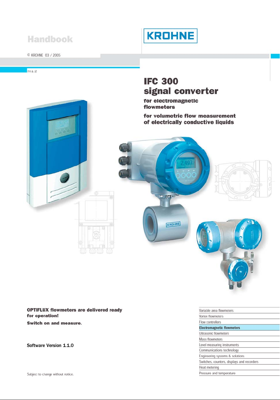
Page 1
Page 2

Contents
• CE / EMC / Standards / Approvals 3
• Safety information 4
• System description 4
• Product liability and warranty 4
• Items included with supply 5
• Signal converter versions and device nameplates 5
1 Electrical connection: power supply 6 - 15
Location and important notes on installation PLEASE NOTE !
1.1
6 - 7
1.2 Connection to power for IFC 300 versions C, F and W 8
1.3 Electrical connection of remote sensors (primary heads) 9 - 15
1.3.1 General information on signal cables A and B, and field current cable C 9
1.3.2 Stripping (preparation) of signal cables A and B 10
1.3.3 Type, length and preparation of field current cable C 11
1.3.4 Grounding of sensors (primary heads) 12
1.3.5 Length of signal cable
max. distance between signal converter and sensor (primary head) 13
1.3.6 Connection diagrams (I and II) for power supply and sensors 14 - 15
2 Electrical connection: outputs and inputs 16 - 28
Important information on outputs and inputs PLEASE NOTE !
2.1
16
2.2 I / O assemblies 16-18
2.3 Current output 19
2.4 Pulse and frequency output 20
2.5 Status output and limit switches 21
2.6 Control input 22 - 23
2.7 Connection diagrams (1 - 17) for inputs and outputs 24 - 28
3 Start-up 29
2 IFC 300 03 / 2005
Page 3

4 Operator control of the signal converter 30 - 51
4.1 Display, operating and control elements 30
4.2 Function of the keys 31
4.3 KROHNE program structure for EMFs 32
4.4 Tables of settable functions 33 - 43
4.5 To reset counters 44
4.6 To delete error messages 44
4.7 General directions for special measurements, tasks and diagnostics 45
4.8 Special measurements 46
4.9 Special measurement tasks and diagnostics 46 - 47
4.10 Status messages and diagnostic information 48 - 51
5 Technical data 52 - 59
5.1 IFC 300 signal converter 52 - 55
5.2 Selection table for KROHNE sensors (primary heads) 56
5.3 Flow table 56
5.4 Measuring accuracy / error limits 57
5.5 Dimensions and weights 58
• If you need to return flowmeters to KROHNE for testing or repair 59
• Form to accompany a returned device (can be copied) 59
CE / EMC / Standards / Approvals
The electromagnetic flowmeters from KROHNE described in this handbook meet
the following safety requirements:
• EMC Directive 89 / 336 / EEC and 93 / 68 / EEC
in conjunction with EN 61326-1 (1997) and A1 (1998), A2 (2001)
• Low-Voltage Directives 73 / 23 / EEC and 93 / 68 / EEC
in conjunction with EN 61010-1: 2001
• Pressure Equipment Directive 97 / 23 / EC
• Ex Directive 94 / 9 / EC (ATEX 100a) for versions designed for use in
hazardous areas
• All devices bear the CE marking and meet the requirements of
•
NAMUR Guideline NE 21 / 04 with IFC 300 signal converter.
03 / 2005 IFC 300 3
Page 4
Safety information
Please read these operating instructions and observe applicable national standards, safety requirements and
accident prevention regulations.
Installation and operation of the measuring device may only be carried out by qualified personnel.
Warning sign:
electric shock
hazard
Separate
manuals
available for
hazardousduty
equipment!
WARNING!
CAUTION!
Info Information and tips
WARNING!
Electric shock is dangerous and can cause severe burns and critical injuries!
CAUTION!
Special regulations apply to use of equipment in hazardous areas, and these must
be observed without fail in order to ensure safe operation in such areas. Wiring,
installation, operation and maintenance may only be carried out by qualified
personnel trained in explosion protection.
WARNING!
Indicates activities or occurrences which, if ignored, can lead to serious personal
injury, hazardous situations, faulty operation or destruction of the device.
CAUTION!
Indicates activities or occurrences which, if ignored, can lead to personal injury and
faulty operation of the device.
System description
Electromagnetic flowmeters are precision instruments designed for linear flow measurement of liquid products.
The process liquids must be electrically conductive, ≥ 1 µS/cm (depending on the sensor);
for cold demineralized water: ≥ 20 µS/cm.
The full-scale range Q
flow velocity between v = 0.3 – 12 m/s, see flow table in Sect. 5.3.
can be set as a function of the sensor meter size (primary head) in keeping with the
100%
Product liability and warranty
Electromagnetic flowmeters from KROHNE are designed solely for measuring the flow rate and the
conductivity of electrically conductive process liquids.
Such flowmeters are also available for use in hazardous areas.
Special regulations apply in this case, which are given in the special EEx directions,
see separate operating instructions.
Responsibility as to suitability and intended use of these electromagnetic flowmeters rests solely with the
operator.
Improper installation and operation of the flowmeters (systems) may lead to loss of warranty.
In addition, the “General conditions of sale“ forming the basis of the purchase contract are applicable.
If flowmeters need to be returned to KROHNE, please note the information given on the last-but-one page of
these Instructions. KROHNE regret that they cannot repair or check your flowmeter(s) unless they are
accompanied by the completed form sheet.
4 IFC 300 03 / 2005
Page 5
• Signal converter in the version as ordered.
• Signal cable (only for remote versions F and W) in the version and length as ordered
(Standard: signal cable A, length 5 m)
• Report on factory settings
• Calibration report
• Quick Start directions, in the language ordered, for installation, electrical connection, start-up and
operator control of the signal converter.
• CD-ROM with manuals for the sensors and the signal converter.
Items included with supply
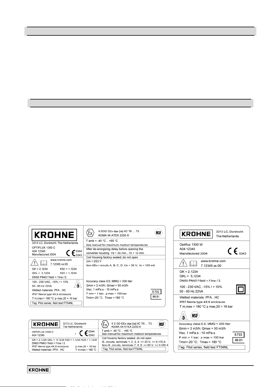
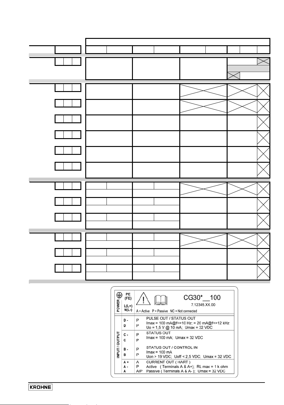
Signal converter versions and device nameplates
Your measuring device is delivered in ready-to-operate condition. Operating data have been factory-set to
your order. The signal converter is equipped as standard with a local display, operator control elements and
with a HART
IFC 300 C Compact flowmeter,
IFC 300 F Signal converter in field housing, remote version,
IFC 300 W
IFC 300 R Signal converter in 19“ rack, remote version,
C and F (option) These versions available for use in hazardous areas.
®
interface
signal converter mounted directly on the flow sensor
electrical connection to the flow sensor via field current and signal cables
Signal converter in wall-mounted housing, remote version,
electrical connection to the flow s
ensor via field current and signal cables
electrical connection to the flow sensor via field current and signal cables (in preparation)
Please check against the device nameplates that the device supplied is in the correct version,
see following examples. The nameplate for inputs/outputs is illustrated in Sect. 2.2.
Examples for nameplates
03 / 2005 IFC 300 5
Page 6

1 Electrical connection: Power supply
1.1 Location and important notes on installation PLEASE NOTE !
• Electrical connection in conformity with VDE 0100 “Regulations for electrical power
installations with line voltages up to 1000 V“ or equivalent national regulations.
• Use separate entry fittings (PG screwed cable entries) for power supply, field current and
signal cables, and for outputs and inputs.
• Protect signal converter against direct solar radiation, install a sunshade if necessary.
• Signal converters installed in switchgear cabinets require adequate cooling, e.g. by fan or
heat exchanger.
• Do not expose signal converters to intense vibration.
KROHNE OPTIFLUX are tested at vibrational level to IEC 68-2-34:
broadband vibration test: f
spectral acceleration density ASD = 0.01 g
• Dimensions of the signal converter, see Sect. 5.5.
For separate systems / remote signal converters only (F and W versions)
• Mounting of the remote signal converter
• Mounting of the IFC 300 W:
Remove mounting plate from rear of signal converter, and attach to wall or standpipe. Replace
signal converter. Position lock washers and nuts on the housing bolts, tighten nuts slightly.
Align housing, tighten nuts firmly.
Dimensions, further information (minimum distances between signal converters):
see Sect. 5.5, Dimensions and weights
• Mounting the IFC 300 F:
Mount IFC 300 F with mounting plate on wall or standpipe.
Dimensions, further information (minimum distances between signal converters):
see Sect. 5.5, Dimensions and weights
• Keep distance between flow sensor and signal converter as short as possible, observe
max. allowed length of signal and field current cables, see Sect. 1.3.3 and 1.3.5.
• Use the supplied KROHNE signal cable A (type DS 300, standard) or B (type BTS 300,
bootstrap, optional), standard length 5 m / 15 ft.
• Generally use bootstrap signal cables B (type BTS 300) for OPTIFLUX 5000 F and OPTIFLUX
6000 F flow sensors, meter sizes DN 2.5 - 15 and
which tend to form electrically insulating deposits.
• Always calibrate flow sensor and signal converter together! Also install together and make
sure settings of the primary constant GK / GKL are identical, see device nameplates and
report on settings for the signal converter.
If components are supplied separately, or in the case of a “mixed“ installation, the signal
converter must be set to the DN size and GK / GKL of the sensor; see Sect. 4.
= 20 Hz / f2 = 2000 Hz / t = 90 min. / Test in all three axes (directions),
1
2
/ Hz (a
= 4.5 g).
eff.
1
/10” – 1/2”, and for contaminated liquids
6 IFC 300 03 / 2005
Page 7
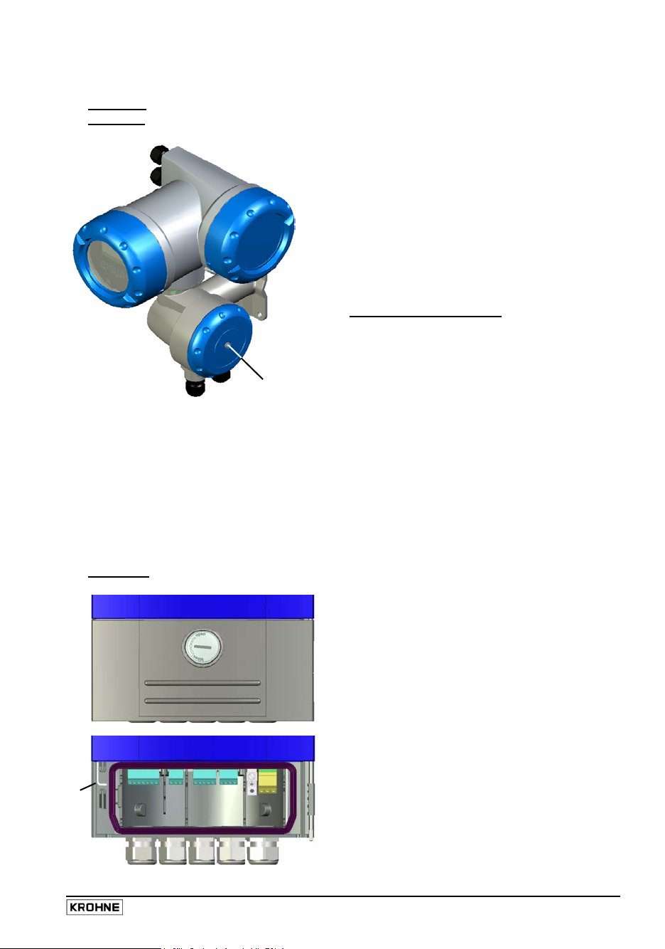
• Construction of the various housing versions
IFC 300 C
IFC 300 F
(compact) and
(remote)
3
The terminal compartments are accessible
after unscrewing cover 2
4
(and 5, for F Version only).
1 Cover, electronics compartment
2 Cover, terminal compartment for
power supply and inputs/outputs
2
3 Cable entry for power
4 Cable entry for inputs/outputs
1
8
for F Version only (remote)
5 Cover, sensor terminal compartment
5
6 Cable entry for field current cable
7 Cable entry for signal cable
The display of the IFC 300 C and IFC 300 F can be turned in steps of 90°.
To do this, unscrew the cover of the electronics compartment and remove the two metal clips to the left and
right of the display using a screwdriver or similar tool. The display between the metal clips can then be pulled off
and re-inserted in the required position. Before pushing the clips together with the display into the electronics
compartment, make sure not to kink the display´s flat ribbon cable more than absolutely necessary. Replace
cover and tighten down by hand.
Cover threads to be protected from dirt and well greased at all times;
particularly important for hazardous-duty (Ex) versions!
6
7
9
8 Attachment plate for wall or pipe mounting
9 Locking screw for cover of
sensor terminal compartment(5)
IFC 300 W (remote)
1
1 Cover, electronics compartment
2 Cover for the three separate terminal
3
2
compartments for power, sensor connection
and inputs/outputs
3 Locking screw,
1
/2 turn left/right
to open/close cover (2)
4 Safety lever to open cover (1)
1
5 Sensor terminal compartment,
open separate cover
6 Terminal compartment, outputs/inputs
7 Power terminal compartment,
4
5
6
7
open separate shock-hazard protection cover
8 Entry fitting for signal cable
9 Entry fitting for field current cable
10 Two cable entries for outputs/inputs
8 9
10
11
11 Cable entry for power supply
03 / 2005 IFC 300 7
Page 8
1.2 Connection to power for IFC 300 versions C, F and W
PLEASE NOTE !
• Degree of protection IP 65 and 67 to IEC 529 / EN 60529, equivalent to NEMA 4 / 4X and 6,
dependent on the version.
• Rated values: The housings of the flowmeters, which are designed to protect the electronic
equipment from dust and moisture, should be kept well closed at all times. Creepage
distances and clearances are dimensioned to VDE 0110 and IEC 664 for pollution severity 2.
Supply circuits are designed for overvoltage category III and the output circuits for overvoltage
category II.
• Fuse protection, disconnecting device:
circuit, and also a disconnecting device (switch, circuit breaker) to isolate the signal converter
must be provided.
100-230 Volt AC (tolerance range -15% / +10%)
• Note the data on the nameplate, power supply voltage and frequency range (50 - 60 Hz).
• The protective ground conductor PE of the power supply must be connected to the
separate terminal in the terminal compartment of the signal converter.
• Connection diagrams I - II for the power supply and the electrical connection between flow
sensor (primary head) and signal converter: see Sect. 1.3.6.
12 - 24 Volt DC (tolerance range -25% / +30%)
• Note the data on the instrument nameplate!
• For reasons to do with the measurement process, connect a functional ground FE to the
separate U-clamp terminal in the terminal compartment of the signal converter.
• When connecting to functional extra-low voltages, provide a facility for protective separation
(PELV) (VDE 0100 / VDE 0106 and/or IEC 364 / IEC 536 or relevant national regulations).
• Connection diagrams I - II for the power supply and the electrical connection between flow
sensor and signal converter: see Sect. 1.3.6.
Connection to power (applies to all versions / housing versions)
Fuse protection (IN ≤ 16 A) for the infeed power
Power consumption
• for AC = 22 VA
• for DC = 12 W
AC: 100 - 230 V (-15% / +10%)
DC: 12 - 24 V (-25% / +30%)
The power terminals in the terminal compartments are protected by additional
hinged lids against accidental contact.
shock hazard. All directions, operating data and connection diagrams do not apply to
8 IFC 300 03 / 2005
PE
FE
Warning: Signal converter must be properly grounded to avoid personnel
devices used in hazardous areas; in such cases, read the special “Ex“ operating
instructions without fail!
N
L-
L
L+
Page 9
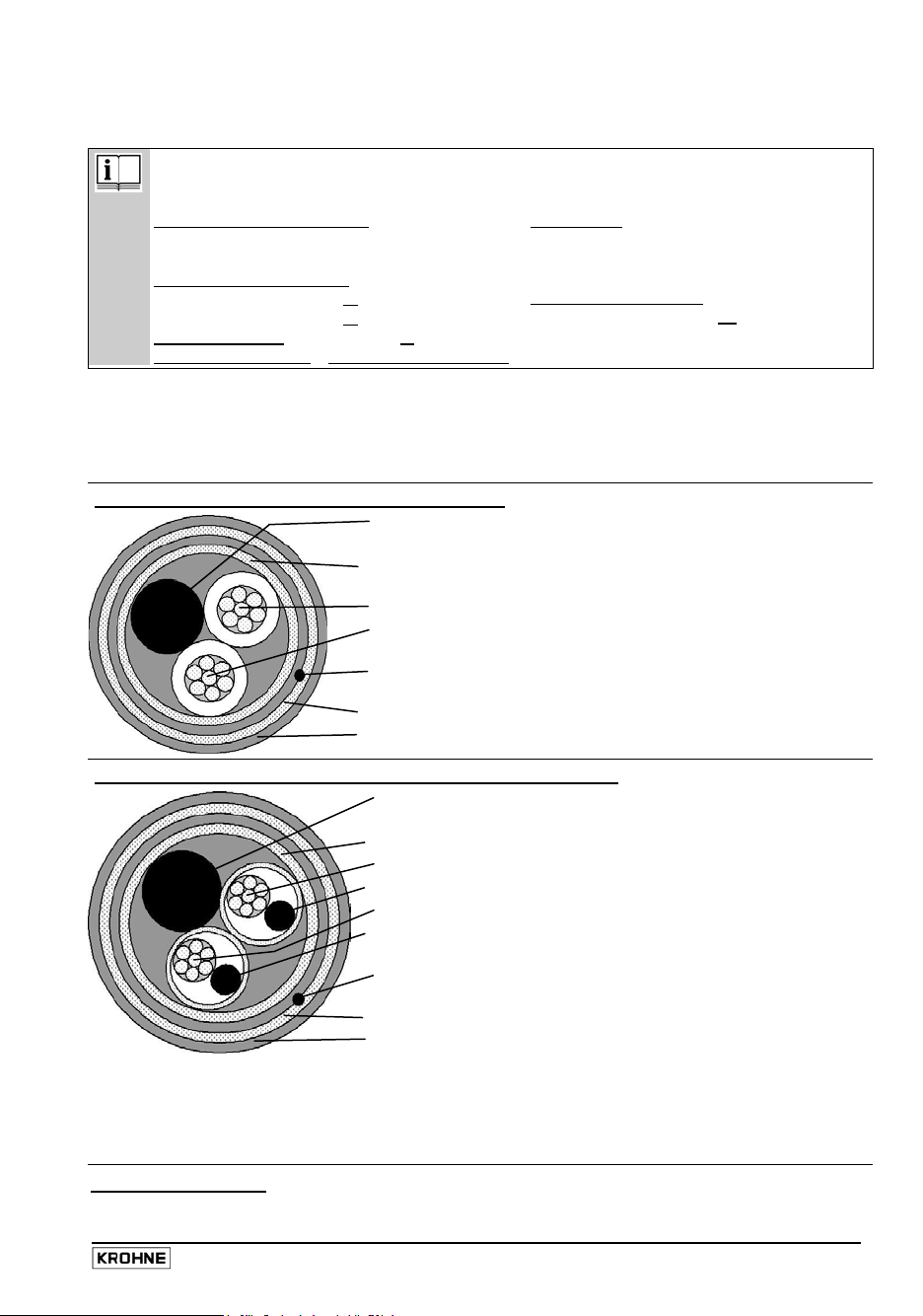
1.3 Electrical connection of remote sensors (primary heads)
1.3.1 General information on signal cables A and B and field current cable C
• Lay signal cables as a fixed installation, underwater and underground laying possible.
• Connection of shields: - inner (1) via drain wire to normal connecting terminal
- outer (60) via braid to U-clamp terminal
• Insulating material is flame-retardant to EN 50625-2-1,IEC 60322-1.
• The low-halogen, unplasticized signal cables remain flexible at low temperatures.
Signal cable A (type DS 300), with double shielding
Signal cable B (type BTS 300) with triple shielding (bootstrap line)
In the bootstrap method, the individual shields (20 and 30) are always controlled by the signal converter
to exactly the same voltage that is present at signal wires (2 and 3). Because for that reason there is no
voltage difference between the individual shields (20 and 30) and the signal wires (2 and 3), no current
flows via the line capacitances between 2 / 20 or 3 / 30. The line capacitance is apparently “zero“.
This allows greater cable lengths when the electrical conductivity of the process product is low.
Proper functioning is ensured by the KROHNE signal cables A and B with double or
triple foil shielding.
However, when other signal cables are used, please note the following electrical data!
Electrical safety to EN 60811
(
low-voltage directives)
or equivalent national standards.
Capacitance of signal wire
wire / wire < 50 pF/m or
wire / shield < 150 pF/m or
Isolation resisance >100 GΩ × km or >60 GΩ × mile
15 pF/ft
45 pF/ft
Test voltage
Signal wire / inner shield 500 V
Signal wire / signal wire 1000 V
Signal wire / outer shield 1000 V
Twisting of signal wires
minimum 10× per meter or
3× per feet,
important when screening magnetic fields
Voltage rating < 24 V / Current rating < 100 mA
Stranded drain wire, inner shield,
1
1.0 mm² Cu / AWG 17 (not insulated, bare)
Inner shield (see stranded drain wire 1)
10
Insulated conductor, 0.5 mm² / AWG 20 (marking = 2)
2
Insulated conductor, 0.5 mm² / AWG 20 (marking = 3)
3
Stranded drain wire, outer shield,
6
0.5 mm² Cu / AWG 20 (not insulated, bare)
Outer shield (see stranded drain wire 6)
60
Outer sheath, dia. approx. 8 mm / 0.3” (marking = DS 300)
Stranded drain wire, inner shield,
1
1.0 mm² Cu / AWG 17 (not insulated, bare)
Inner shield (see stranded drain wire 1)
10
Insulated conductor, 0.5 mm² / AWG 20 (marking = 2)
2
Stranded drain wire for individual shield of conductor 2
20
Insulated conductor, 0.5 mm² / AWG 20 (marking = 3)
3
Stranded drain wire for individual shield of conductor 3
30
Stranded drain wire, outer shield,
6
0.5 mm² Cu / AWG 20 (not insulated, bare)
Outer shield (see stranded drain wire 6)
60
Outer sheath, dia. approx. 12 mm / 0.5“ (marking = BTS 300)
Field current cable C
Cross-section dependent on required length of cable, see Table in Sect. 1.3.3.
03 / 2005 IFC 300 9
Page 10
3
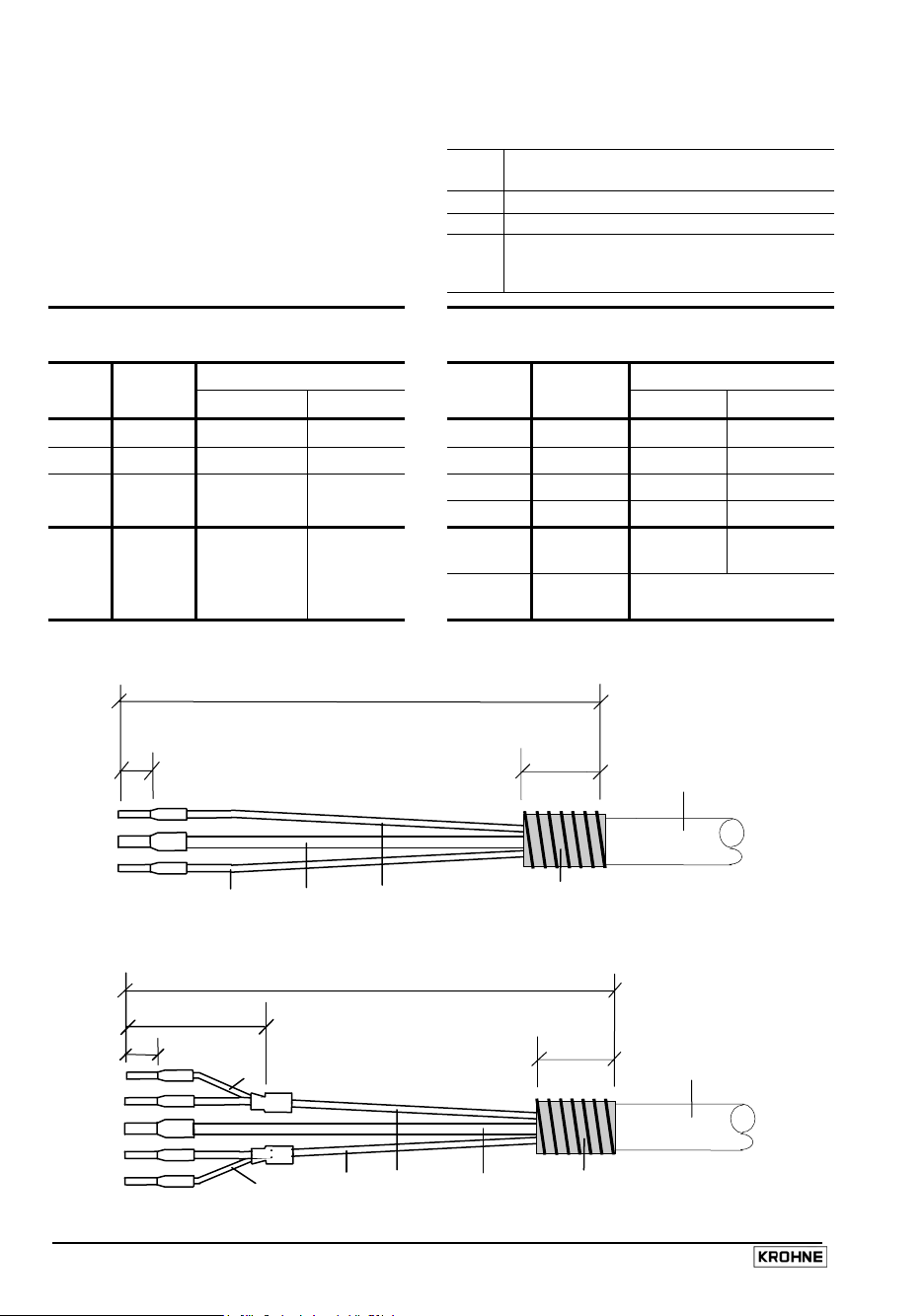
1.3.2 Stripping (preparation) of signal cables A and B
Please note:
• The figures in tables and drawings
identify the shields,
stranded drain wires and wires of signal
cables A and B, see Sect. 1.3.1.
• The following tables and drawings indicate
the dimensions (a - d) for stripping the
Customer-supplied materials
W
Insulation tubing (PVC),
dia. 2.0-2.5 mm / approx. 0.1”
X
Heat-shrinkable tubing or cable sleeve
Y
Wire end ferrule to DIN 41 228: E 1.5-8
Z
Wire end ferrule to DIN 41 228: E 0.5-8
signal cables.
Signal cable A ( Typ DS 300) Signal cable B (Typ BTS 300)
approx. Length in mm / inch approx. Length in mm / inch
dimen-
Sensor
sion
a
60 / 2.4“ 90 / 3.5“ 90 / 3.5“
b
10 / 0.4“ 10 / 0.4“ 10 / 0.4“
c
8 / 0.3“ 8 / 0.3“ 8 / 0.3“
60
connect connect
20 / 30
Signal converter Signal converter
IFC 300 F IFC 300 W
dimen-
sion
a
b
c
Sensor
60 / 2.4“ 90 / 3.5“ 90 / 3.5“
10 / 0.4“ 10 / 0.4“ 10 / 0.4“
8 / 0.3“ 8 / 0.3“ 8 / 0.3“
d -
do not
connect
60
connect connect
do not
connect
IFC 300 F IFC 300 W
25 / 1.0“ 25 / 1.0“
do not
connect
connect only
in the IFC 300
Signal cable A (type DS 300), with double shielding
a
c
Z
Y
Z
W
Signal cable B (type BTS 300), with triple shielding (bootstrap)
Z
Z
Y
Z
d
c
30
W
20
a
2
3
1
Signal cable A
b
bending radius
≥ 50 mm / ≥ 2.0”
(Slip shield over outer sheath
60
and connect up.)
Signal cable B
b
bending radius
≥ 50 mm / ≥ 2.0”
(Slip shield over outer sheath
60
and connect up.)
10 IFC 300 03 / 2005
Page 11
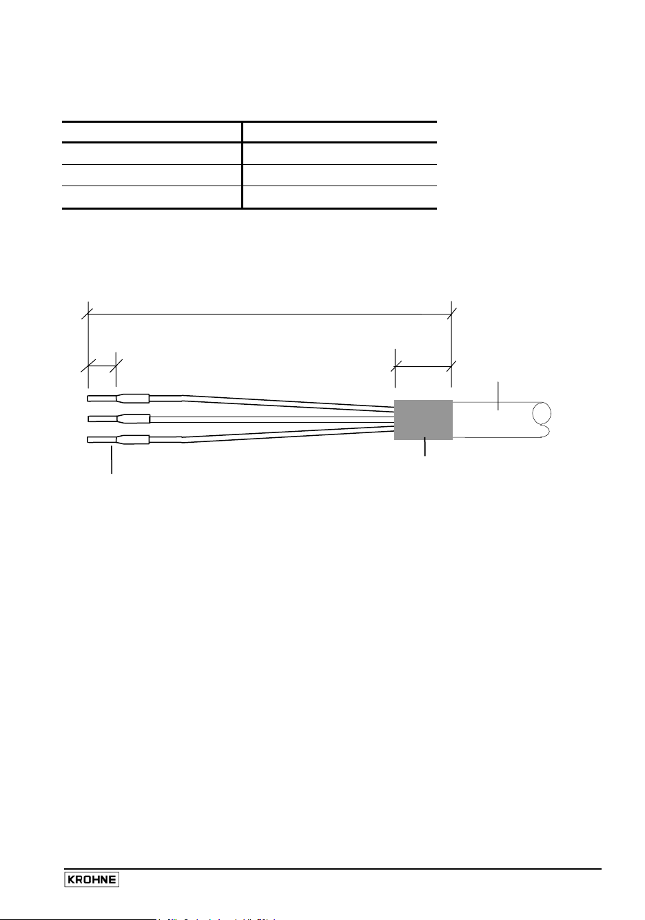
1.3.3 Type, length and preparation of the field current cable C
Length and cross-section, field current cable C
Length Cross-section A
(Cu)
F
Cu = copper cross-section
0 – 150 m 0 - 500 ft 3 x 0.75 mm² Cu 3 x AWG 18
150 – 300 m 500 - 1000 ft 3 x 1.50 mm² Cu 3 x AWG 14
300 – 600 m 1000 - 2000 ft 3 x 2.50 mm² Cu 3 x AWG 12
For the IFC 300 W the terminals are designed for the following cable cross-sections:
• flexible cable: ≤ 1.5 mm² / ≤ AWG 14
• solid cable: ≤ 2.5 mm² / ≤ AWG 12
Preparation
e
90 mm / 3.5“
10 mm
0.4“
Field current
cable C
bending radius
50 mm / 2“
Wire end ferrules,
Size and dimension e
dependent on dia. of cable
Only if using a shielded
field current cable: cut back, slip
shield over the outer sheath and
connect up only in the sensor
connection box.
03 / 2005 IFC 300 11
Page 12
1.3.4 Grounding of sensors (primary heads)
• The sensor must be properly connected to ground.
• The grounding cable should not transmit any interference voltages.
• Do not use the grounding cable to connect more than one device to ground.
• In hazardous areas, grounding is used at the same time for equipotential bonding. Special
grounding instructions are contained in the “Ex-installation instructions“, which are only
supplied together with hazardous-duty equipment.
• The sensors are connected to ground by means of a functional grounding conductor FE.
• Special grounding instructions for the various sensors are contained in the separate
installation instructions for the sensors.
• These instructions also contain detailed descriptions on how to use grounding rings and how
to install the sensors (primary heads) in metal or plastic pipes or in pipes which are coated on
the inside.
Warning: The signal converter must be properly grounded to avoid personnel
shock hazard. All diections, operating data and connection diagrams do not apply to
devices used in hazardous areas; in such cases, read the special “Ex“ operating
instructions without fail.
12 IFC 300 03 / 2005
Page 13
A
g
[
]
g
[
]
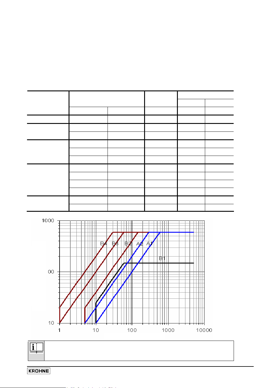
1.3.5 Length of signal cable
max. distance between signal converter and sensor (primary head)
Abbreviations and explanatory notes
for the following table, diagram and connection diagrams
A
Signal cable A / type DS 300, double shielding, max. length: see diagram below
B
Signal cable B / type BTS 300, triple shielding, max. length: see diagram below
C
Field current cable, cross-section and length: see Sect. 1.3.3
Electrical conductivity of process liquid
σ
Sensor
primary head
OPTIFLUX 1000 F
OPTIFLUX 2000 F
OPTIFLUX 4000 F
OPTIFLUX 5000 F
OPTIFLUX 6000 F
m
th
Meter size Min. elec. - Curve for signal cable
conductivity A
DN mm inches µS / cm DN mm
10
25
200
2.5 - 6 1/10 - 1/
10
200
2.5
4
25
150
-
150 3/8 - 6 5
-
150 1 - 6 20
-
2000 8 - 80 20
6
150 3/8 - 6 1
-
2000 8 - 80 1
1
/10 10
-
15 1/6 - 1/
-
100 1 - 4 1
-
250 6 - 10 1
2
10
5
2.5 - 15 1/10 - 1/2 10
25 - 150 1 - 6 1
A 1 B 2
A 1 B 3
A 2 B 4
- B 1
A 1 B 3
A 2 B 4
- B 1
- B 2
A 1 B 3
A 2 B 4
- B 1
1B 3
3000
ft
th
300
max. cabel len
max. cabel len
30
Please note !
For process temperatures above 150°C, special cables and a through-box ZD
electrical conductivity [µS/cm]
are required. Optionally available, incl. modified circuit diagrams.
03 / 2005 IFC 300 13
Page 14
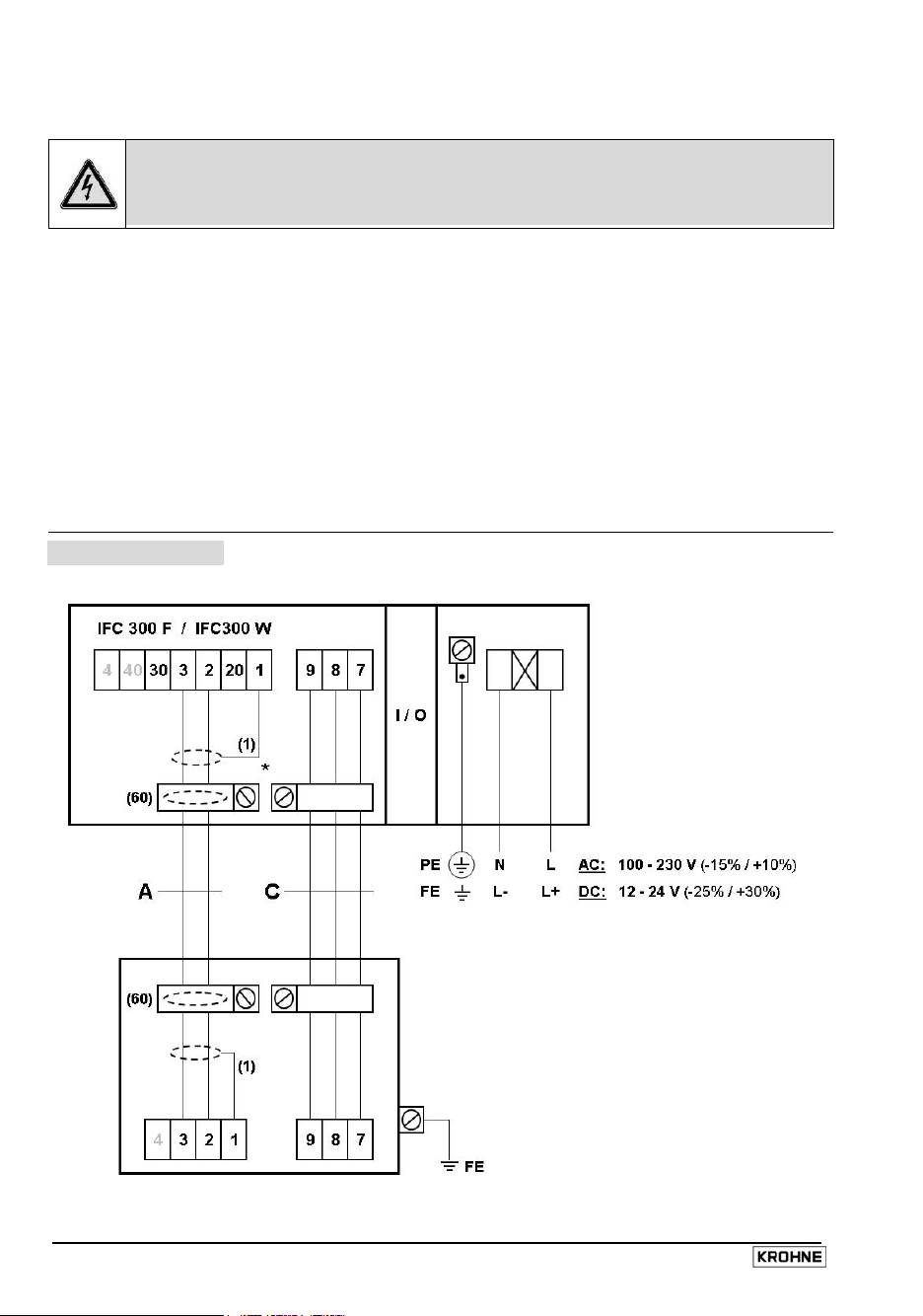
1.3.6 Connection diagrams (I and II) for power supply and sensors
Important notes for connection diagrams PLEASE NOTE !
Warning: Signal converter must be properly grounded to avoid personnel shock hazard.
All directions, operating data and connection diagrams do not apply to
devices used in hazardous areas; in such cases, read the special “Ex“ operating
instructions without fail!
• The figures in brackets identify the shields, stranded drain wires and cores of signal
cables A + B, see sectional drawings of signal cables in Sect. 1.3.1.
• Electrical connection to VDE 0100 “Regulations governing heavy-current installations with
line voltages up to 1000 V“
• Power supply 12 - 24 V DC:
Functional extra-low voltage with safety separation
(PELV) to VDE 0100/VDE 0106 and/or IEC 364/IEC 365,
or equivalent national regulations.
• Systems used in hazardous areas are subject to special regulations concerning electrical
connections (see separate manual).
• Terminal 4 / 40: assigned only when sensors have 4 electrodes (special version)
• PE = protective conductor
I
Signal cable A / Type DS 300
FE = functional ground
Power consumption
• for AC = 22 VA
• for DC = 12 W
* These two cable
terminals are not
provided in the housing
of the IFC 300 W,
therefore, do not connect
up the outer shield of
cables A and C!
Sensor / primary head
14 IFC 300 03 / 2005
Page 15
For IFC 300 F !
• IFC 300 F has separate terminal compartments for power supply,
flow sensor and for outputs and inputs.
• Connect the two overall shields for signal cables A and B in the sensor outlet box and
in the signal converter-sensor terminal compartment:
inner shield (10) by way of the stranded drain wire (1), and
outer shield (60) by way of the braid.
• There should be no difference in potential between the sensor and the housing
of the signal converter!
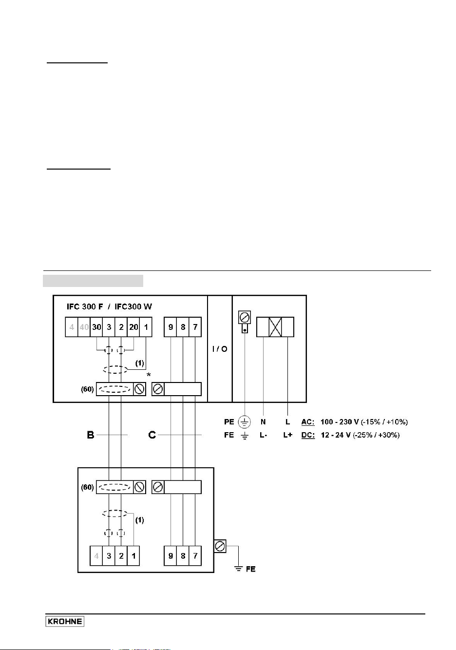
For IFC 300 W !
• IFC 300 W has 1 cover for the separate terminal compartments for power supply, sensor and
for outputs and inputs. The power terminal compartment has an additional hinged flap for
shock-hazard protection.
• The outer overall shield (60) of signal cables A and B can only be connected up in the sensor
outlet box!
II
Signal cable B / Type BTS 300
Power consumption
• for AC = 22 VA
• for DC = 12 W
* These two cable
terminals are not
provided in the housing
of the IFC 300 W,
therefore, do not
connect up the
outer shield of
cables B and C!
Sensor / primary head
03 / 2005 IFC 300 15
Page 16
2 Electrical connection: outputs and inputs
2.1 Important information for outputs and inputs PLEASE NOTE !
• The output / input groups are galvanically separated from each other and from all other
input and output circuits.
• Active mode:
The signal converter supplies the power for operation (activation) of
receiver instruments; observe max. operating data.
• Passive mode:
Operation (activation) of receiver instruments requires an external power
supply (U
); observe max. operating data.
ext
• Connection diagrams of outputs and inputs are shown in Sect. 2.7.
• For operating data of outputs and inputs, refer to Sect. 2.7 and 5.1.
2.2 I / O assemblies for the outputs and inputs
IFC 300 is available with a choiceof output/input assemblies:
• The Basic I/O has one mA, one pulse and 2 status outputs. The pulse output can be set as a status
output, and one of the status outputs as a control input (see Basic I/O table).
• The Modular I/O can be equipped with different output modules, depending on the task (see
Modular I/O table).
• For hazardous areas, all I/O variants are available for the IFC 300 C (compact) and
IFC 300 F (remote) with terminal compartment in EEx - d (flameproof enclosure) or
EEx - e (increased safety) protection.
• The Bus - System I/O allows intrinsically safe and non-intrinsically safe bus interfaces in combination
with further modules (see Bus - System I/O table).
• The last 3 places of the CG No. indicate the assigned terminals,
see examples below.
• Abbreviations used are explained in the small table on the next but one page.
Examples of CG No. to identify the electronic module and the I/O variants:
CG30* _ _ 4 _ _ (see sticker inside cover of terminal compt)
General type designation 2nd option module for terminal B
Power 1st option module for terminal A
Display version I/O version identified by this place
(here: Modular I/O), fixed assignment of terminals C+D
(according to the 1st place of the CG No.)
CG No. (examples)
CG 300 11 100 100-230 V AC & Standard Display / Basic I/O:
CG 300 11 7FK 100-230 V AC & Standard Display / Modular I/O:
CG 300 81 4EB 24 V DC & Standard Display / Modular I/O:
16 IFC 300 03 / 2005
or Ip & Sp/Cp & Sp & Pp/S
I
a
p
(see Tabele and Nameplate on the next page)
& Pn/Sn and option module PN/SN & C
I
a
N
(see Tables on the next but one page)
& Pa/Sa and option module Pp/Sp & I
I
a
p
(see Tables on the next but one page)
Page 17
Fixed, unalterable I/Os (input/output versions)
Terminals
I/Os CG-No. D- D C- C B- B A- A A+
Basic 1 0 0
Standard
EEx - i 2 0 0
Option
3 0 0
2 1 0
3 1 0
2 2 0
3 2 0
(changeable)
P
/ SN NAMUR
N
(changeable)
P
/ SN NAMUR
N
(changeable)
P
/ SN NAMUR
N
(changeable)
P
/ SN NAMUR
N
(changeable)
P
/ SN NAMUR
N
(changeable)
P
/ SN NAMUR
N
(changeable)
P
/ Sp
p
S
p
I
+ HART® active
a
I
+ HART® passive
p
I
+ HART® active
a
I
+ HART® passive
p
I
+ HART® active
a
I
+ HART® passive
p
PA - Bus D 0 0 Term PA- Term PA+ Term PA- Term PA+
PROFIBUS
(EEx-i)
Option
D 1 0 Term PA- Term PA+ Term PA- Term PA+
D 2 0 Term PA- Term PA+ Term PA- Term PA+
FISCO Device FISCO Device
FISCO Device FISCO Device
FISCO Device FISCO Device
FF - Bus E 0 0 Term V/D- Terrm V/D+ Term V/D- Terrm V/D+
Foundation
FISCO Device FISCO Device
Field-Bus E 1 0 Term V/D- Terrm V/D+ Term V/D- Terrm V/D+
(EEx-i)
Option
FISCO Device FISCO Device
E 2 0 Term V/D- Terrm V/D+ Term V/D- Terrm V/D+
FISCO Device FISCO Device
/ Cp
S
p
(changeable)
/ SN / CN NAMUR
P
N
(changeable)
/ SN / CN NAMUR
P
N
(changeable)
/ SN / CN NAMUR
P
N
(changeable)
/ SN / CN NAMUR
P
N
(changeable)
P
/ SN / CN NAMUR
N
(changeable)
P
/ SN / CN NAMUR
N
(changeable)
/ SN / CN NAMUR
P
N
(changeable)
P
/ SN / CN NAMUR
N
(changeable)
Ip + HART®
or (reverse term.)
Ia + HART®
I
a
I
a
I
p
I
p
I
a
I
p
I
a
I
p
Nameplate inputs/outputs
Example of CG No., here:
BASIC I/O
03 / 2005 IFC 300 17
Page 18
Alterable I/Os (input/output versions)
• The grey boxes denote freely selectable option modules for terminals A and B.
• Terminal A+ functions only for the Basic I/O.
• For hazardous areas, all I/O variants for IFC 300 C and IFC 300 F are available with
terminal compartment in EEx - d (flameproof enclosure) or EEx - e (increased safety) protection.
Terminals
I/Os CG-No. D- D C- C B- B A- A A+
Modular 4 _ _
Option
_ _
8
_ _
6
_ _
B
_ _
7
_ _
C
PA - Bus D _ _
PROFIBUS
Option
FF - Bus E _ _
Foundation Field-Bus
Option
DP - Bus F _ 0
PROFIBUS
Option
P
P
P
Term
PA-
Term
V/D-
/ Sa
a
(changeable)
P
/ Sa
a
(changeable)
P
/ Sp
p
(changeable)
/ Sp
P
p
(changeable)
/ SN NAMUR
N
(changeable)
/ SN NAMUR
N
(changeable)
Term PA+
Terrm
V/D+
I
+ HART® active
a
I
+ HART® passive
p
I
+ HART® active
a
I
+ HART® passve
p
I
+ HART® active
a
I
+ HART® passve
p
Term
PA-
Term
V/D-
Term
PA+
Terrm
V/D+
max. 2 option modules for
term. B + A: Ia or Pa / Sa or Ca
max. 2 option modules for
term. B + A: Ip or Pa / Sa or Ca
max. 2 option modules for
term. B + A:
Ia or Pp / Sp or Cp
max. 2 option modules for
term. B + A: Ip or Pp / Sp or Cp
max. 2 option modules for
term. B + A: Ia or PN / SN or CN
max. 2 option modules for
term. B + A: Ip or PN / SN or CN
max. 2 option modules for
term. B + A: Ia or Pa / Sa or Cp
max. 2 option modules for
term. B + A: Ia or Pa / Sa or Cp
RxD/TxD N RxD/TxDP RxD/TxDN Termin.N RxD/TxDP Termin.
P
max. 1 option
module for
term. A:
see table
below for
selection
Option modules
Abbreviation Description Ident
for CG No.
Ia
Ip
Pa / Sa
Pp / Sp
PN / SN
Ca
Cp
CN
Active current output
Passive current output
Active pulse, frequency, status output or limit switch
Passive pulse, frequency, status output or limit switch
Pulse, frequency, status output or limit switch to NAMUR
Active control input
Passive control input
Control input to NAMUR
- No module installed
- No further module possible
18 IFC 300 03 / 2005
A
B
C
E
F
G
K
H
8
0
Page 19

2.3 Current output
• Depending on the version, the outputs and inputs to be connected passively or
actively and / or to NAMUR EN 60947-5-6! The tables in Sect. 2.2 show which
I/O version and which inputs and outputs are installed in your signal converter,
see also the sticker inside the cover of the terminal compartment.
• All current outputs are galvanically separated from each other and from all other circuits.
• Depending on the version, up to 3 current outputs in parallel can be built in, one always
with HART
• Factory-set data and functions are given in the enclosed report on settings.
• All operating data and functions are settable, see Sect. 4.4.
• Passive mode
• Active mode
• Self-monitoring
• Error message via status output (see Fct. C 2.x.01).
• Current value for error identification adjustable, see Fct. C 2.x.03 (current output).
• Range change, automatically by status output or manually by control input, see Sect. 4.4, Fct.
C 2.x.11 and C 2.x.12 (for current output) and Fct. C 2.x.01 (for status output or control input).
Setting range threshold between 5 - 80% of Q
(appropriate ratio from low to high range of 1:20 to 1:1.25).
The active range is signalled via a status output.
• Forward / reverse flow measurement (F/R mode) is possible, see Fct. C 2.x.07 (current
output) and Fct. C 2.x.01 (status output).
• Connection diagrams, see Sect. 2.7
®
communication (except for Foundation Fieldbus and PROFIBUS).
external power supply U
load impedance R
≤ 1 kΩ at I ≤ 22 mA
L
≤ 32 V DC bei I ≤ 22 mA
ext
(not applicable to EEx-i, see separate Ex – operating instructions)
- interruption of mA loop or
- load impedance too high in mA loop
, ± 0 - 5% hysteresis
100%
Warning! All directions, operating data and connection diagrams do not apply to
devices used in hazardous areas; in such cases, read the special “Ex“
operating instructions without fail!
03 / 2005 IFC 300 19
Page 20

2.4 Pulse and frequency output
• Depending on the version, outputs and inputs to be connected passively or
actively and/or to NAMUR EN 60947-5-6. The tables in Sect. 2.2 show which
I/O version and which inputs and outputs are installed in your signal converter.
See also the sticker inside the cover of the terminal compartment.
• The pulse or frequency output can be set under Fct. C 2.1 Hardware.
• All pulse / frequency outputs are galvanically separated from all other circuits and from
each other.
• Depending on the version, several pulse / frequency outputs can be installed in parallel.
• Factory-set data and functions will be found in the enclosed report on factory settings.
• All operating data and functions are adjustable, see Sect. 4.4.
• Passive mode
requires external power source: U
I ≤ 20 mA at f ≤ 10 kHz (overflow up to f
I ≤ 100 mA at f ≤ 100 Hz
• Active mode
uses internal power source: U
I ≤ 20 mA at f ≤ 10 kHz (overflow up to f
I ≤ 100 mA at f ≤ 100 Hz
• NAMUR mode
passive to EN 60947-5-6, f ≤ 10 kHz, f
• Scaling
Frequency output: in pulses per unit time (e.g. 1000 pulses/s at Q
Pulse output: in pulses per unit volume
• Pulse width
automatic
pulse width von 0.01-2 s
symmetrical, pulse duty factor 1:1, independent of output frequency,
, with fixed pulse width, duty factor approx. 1:1 at Q
adjustable as required for correspondingly low
output frequency.
• Forward / reverse flow measurement (F/R mode) is possible, see Fct. C 2.x.06 or 07
Polarity (frequency/pulse output) and Fct. C 2.x.01 Mode (status output).
• Connection diagrams see Sect. 2.7
Warning! All directions, operating data and connection diagrams do not apply to
devices used in hazardous areas; in such cases,
read the special “Ex“ operating instructions without fail!
≤ 32V DC Uo 1.5V @ 10 mA:
ext
≤ 12 kHz)
max
24 V DC Uo 1.5V @ 10 mA
nom
≤ 12 kHz)
max
≤ 12 kHz
max
(e.g. 100 pulses/m³).
100%
100%
, or
20 IFC 300 03 / 2005
Page 21

2.5 Status output and limit switches
• Depending on the version, the outputs and inputs to be connected passively or
actively and/or to NAMUR EN 60947-5-6! The tables in Sect. 2.2 show which
I/O version and which inputs and outputs are installed in your signal converter.
See also the sticker inside the cover of the terminal compartment.
• Status output or limit switch can be set under Fct. C 2.1 Hardware.
• All status outputs / limit switches are galvanically separated from all other circuits and
from each other.
• Depending on the version, several status outputs / limit switches can be installed in
parallel.
• The output stages of the status outputs / limit switches in simple active or passive mode
act in the same way as relay contacts and can be connected with any polarities.
• Factory-set data and functions are given in the enclosed report on settings.
• All operating data and functions are adjustable, see Sect. 4.4.
• Passive mode
• Active mode
• NAMUR mode
• Status output (adjustable to following operating states, see, Fct. C 2.x.01):
- Application error
- Uncertain measurement
- Polarity, flow (F/R mode/measurement)
- Overrange, flow
- Counter 1 preset value
- Counter 2 preset value
- Empty pipe
• Limit switches (adjustable to following operating states, see Fct. C 2.x.01):
- Flow velocity
- Volume flow
- Mass flow
- Setting of limit value and hysteresis
- Polarity of measured value
- Time constant
• Connection diagrams, see Sect. 2.7
Warning! All directions, operating data and connection diagrams do not apply to
devices used in hazardous areas; in such cases,
read the special “Ex“ operating instructions without fail!
requires external power source:
U
≤ 32V DC: Uo 1.5V @ 10 mA I ≤ 100 mA
ext
uses the internal power supply:
24 V DC Uo 1.5V @ 10 mA: I ≤ 100 mA
U
nom
passive in conformity with EN 60947-5-6
- output A
- output B
- output C
- output D
- off
- Conductivity
- Coil temperature
Fct. C 2.x.02
Fct. C 2.x.03
Fct. C 2.x.04
Fct. C 2.x.02 appears only
when output A - D set under
Fct. C 2.x.01:
- sign
- overrange
- automatic range
03 / 2005 IFC 300 21
Page 22

2.6 Control input
Depending on the version, the outputs and inputs to be connected passively,
actively and/or to NAMUR EN 60947-5-6. The tables in Sect. 2.2 show
which I/O version and which inputs and outputs are installed in your signal converter.
See also the sticker inside the cover of the terminal compartment.
• All control inputs are galvanically separated from all other circuits and from each other.
• Depending on the version, two control inputs can be installed in parallel.
If two are installed, these have to be set to different functions.
• In the passive mode, the control inputs can be operated with any polarity.
• Factory-set data and functions are given in the enclosed report on settings.
• All operating data and functions are adjustable, see Sect. 4.4.
• Passive mode
• Active mode
• NAMUR mode
• Status output (adjustable to following operating states, see Fct. C 2.x.01):
- off
- stop all counters
- stop counter 1 or 2
- reset all counters
- reset counter 1 or 2
- error reset
• Connection diagrams, see Sect. 2.7
Warning! All directions, operating data and connection diagrams do not apply to
devices used in hazardous areas; in such cases,
read the special “Ex“ operating instructions without fail!
requires external power source:
U
≤ 32V DC: Uon 19 V DC U
ext
2.5 V DC
off
uses the internal power supply:
24 V DC I
U
nom
nom
16 mA
to EN 60947-5-6
(Control input active in accordance with NAMUR EN 60947-5-6:
open-circuit and short-circuit monitoring to EN 60947-5-6 (NAMUR) can only be done
from the infeeding device. Due to the principle involved, only monitoring of control
takes place in the signal converter.)
input C
N
- zero output + stop Cnt. (not display)
- all outputs zero (not display, not counters)
- output A, B, C or D zero
- hold all outputs (not display, not counters)
- hold output A, B, C or D
- range change
22 IFC 300 03 / 2005
Page 23

Notes
03 / 2005 IFC 300 23
Page 24

2.7 Connection diagrams of outputs and inputs
• Please note: Depending on the version, connect the outputs and inputs passively,
actively and/or to NAMUR EN 60947-5-6.
• The tables in Sect. 2.2 show which I/O version and which outputs and inputs
are installed in your signal converter. Please note the operating data!
• The following connection diagrams and operating data do not apply to
hazardous-duty equipment (EEx); refer to separate operating instructions for
such equipment.
• Active mode: The IFC 300 supplies the power for operating (driving) the
receiver instruments; note max. operating data.
• Passive mode: An external power source (U
receiver instruments.
• All groups are galvanically separated from each other and from all other input
and output circuits.
• Terminals that are not used should not have any conductive connection to other
electrically conductive parts.
ext
) is required to operate (drive) the
Ia Ip
Pa Pp
PN
Sa Sp
SN
Ca Cp
CN
+
Current output active or passive
Pulse / frequency output active or passive
Pulse / frequency output passive to NAMUR EN 60947-5-6
Status output / limit switch active or passive
Status output / limit switch passive to NAMUR EN 60947-5-6
Control input active or passive
Control input active to NAMUR EN 60947-5-6:
open-circuit and short-circuit monitoring in accordance with EN 60947-5-6 (NAMUR) can
only be done from the infeeding device. Due to the principle involved, only monitoring of
control input CN takes place in the signal converter.
Milliammeter
0 - 20 mA or 4 - 20 mA and others
Counter
• electronic (EC) or
• electromechanical (EMC)
Button, N/O contact or similar
DC voltage source (U
ext
)
external power supply, any connection polarity
DC voltage source (U
ext
)
Connection polarity as shown in the diagrams
Warning! All directions, operating data and connection diagrams do not apply to
devices used in hazardous areas; in such cases,
read the special “Ex“ operating instructions without fail!
24 IFC 300 03 / 2005
Page 25

Basic I / O Connection diagrams 1 - 5
Current output
1 2
active I
Pulse / frequency output
3 4
passive P
HART®
a
p
I ≤ 22 mA
≤ 1 kΩ
R
L
HART®
connection
to Diagr. 16
Current output
passive Ip HART®
Status output / limit switch
passive Sp
I ≤ 22 mA
≤ 32 V DC
U
ext
HART®
connection
to Diagr. 17
f ≤ 10 kHz: I ≤ 20 mA
f ≤ 100 Hz:
I ≤ 100 mA
1.5 V @ 10 mA
U
0
U
≤ 32 V DC
ext
R = 1.2 kΩ / 0.5 W,
only necessary
when using
electronic totalizer
with internal
resistance of
> 5 kΩ
R
i
can also be set as status output, in which case
electrical connection is acc. to Diagram 4
Control input
5
passive C
p
1.5 V @ 10 mA
U
0
U
≤ 32 V DC
ext
I ≤ 100 mA
X = terminals B or D
Uon > 19 V DC
< 2.5 V DC
U
off
U
≤ 32 V DC
ext
I
16 mA @ 24 V
0
can also be set as status output, in which case
electrical connection acc. to Diagram 4
03 / 2005 IFC 300 25
Page 26

Modular I/O and Bus I/O Connection diagrams 6 - 15
X marks the terminals A, B, C or D, depending on the version of the IFC 300,
see tables in Sect. 2.2.
For electrical connection of the Bus Systems, please consult the separate manuals for
Foundation Fieldbus, PROFIBUS PA oder DP.
Current output active Ia ( HART® )
6
I ≤ 22 mA
≤ 1 kΩ
R
L
Please note: Only the current output module for terminals C / C-
Pulse / frequency output active Pa
8
f ≤ 10 kHz: I ≤ 20 mA
f ≤ 100 Hz:
I ≤ 100 mA
1.5 V @ 10 mA
U
0
24 V DC
U
nom
has HART capability, see Diagrams 16 and 17!
f ≤ 10 kHz: I ≤ 20 mA
f ≤ 100 Hz:
U
U
Status output / limit switch
10 11
active S
a
Current output passive Ip ( HART® )
7
I ≤ 22 mA
U
Pulse / frequency output passive Pp
9
R = 1.2 kΩ / 0.5 W,
I ≤ 100 mA
only necessary when
using electronic
1.5 V @ 10 mA
0
totalizer with internal
resistance of
> 5 kΩ
≤ 32 V DC
ext
R
i
Status output / limit switch
passive Sp
≤ 32 V DC
ext
U0 1.5 V @ 10 mA
I ≤ 100 mA
24 V DC
U
nom
1.5 V @ 10 mA
U
0
≤ 32 V DC
U
ext
I ≤ 100 mA
26 IFC 300 03 / 2005
Page 27

Control input active Ca
12
I
16 mA
nom
U
24 V DC
nom
Control input passive Cp
13
> 19 V DC
U
on
U
< 2.5 V DC
off
≤ 32 V DC
U
ext
I
16 mA
nom
Pulse, frequency and status output / limit switch passive PN / SN
14
to NAMUR EN 60947-5-6
Switching amplifier to
NAMUR with internal
voltage source
Control input active C
15
N
to NAMUR EN 60947-5-6
Error
Signal
03 / 2005 IFC 300 27
Page 28

HART® Circuit diagrams 16 - 17
• In the Basic I/O, the current output at terminals A+ / A- / A
is always HART capable!
• In the Modular I/O, only the current output module for
terminals C / C - is HART-capable!
Ia HART® connection active
16
only with Basic I/O terminals A+ / A
only with Modular I/O terminals C / C-
to HART Communicator
R ≥ 230 Ω
Ip HART® connection passive
17
to HART Communicator
only with Basic I / O terminals A / A-
only with Modular I/O terminals C / C-
to next HART® device
I: I0% = 4 mA
Multidrop I: I
U
≤ 32 V DC R ≥ 230 Ω
ext
= 4 mA
fix
28 IFC 300 03 / 2005
Page 29

3 Start-up
• Before connecting to power, please check that the system has been correctly installed in
accordance with Sect. 1 and 2.
• The flowmeter, comprising sensor (primary head) and signal converter, is delivered in ready-
to-operate condition. All operating data have been factory-set according to your order
specifications, see supplied report on settings.
• After switching on the power, a self-test is carried out,
after which the flowmeter immediately starts flow measurements and the display
indicates the current measured values.
• Alternating between the 1
status messages is carried out by actuating key ↑ or ↓. Possible status messages, their
meaning and possible cause are listed in the Status Table in Sect. 4.8.
• The display of the IFC 300 C and IFC 300 F can be turned in steps of 90°.
Unscrew the cover of the electronic compartment and remove the two metal clips to the left
and right of the display using a screwdriver or similar tool. The display between the metal clips
can then be pulled off and re-inserted in the required position. Before pushing the clips
together with the display into the electronic compartment, make sure not to kink the display`s
flat ribbon cable more than absolutely necessary.
Replace cover and tighten by hand.
Cover threads to be protected from dirt and well greased at all times;
This is particularly important for hazardous-duty (Ex) versions.
st
and 2nd measured value window and – if provided - the list of
03 / 2005 IFC 300 29
Page 30

4 Operator control of the signal converter
4.1 Display, operating and control elements
Graphics display, backlit (white)
1
1st and 2nd display line to indicate different
2
measured variables,
shown here in large format for only one
measured variable
3rd display line, shown here as bar graph
3
Optical keys for operating the signal con-
4
verter without opening the housing
Blue bar indicates …
5
• the tag no. in the measuring mode
• the menu/ function name in the setting mode
6
X indicates actuation of a key
4
3
7
2
5
6
1
9
8
• Display –
for selection of menu and functions
• Display –
for setting of data, functions, etc.
• Display after data, functions, etc.
have been changed
indicates IR transmission in operation; the
4 optical keys then have no function
7
signals a status message
in the status list
Socket for connection to the
8
KROHNE GDC bus
Optical interface for wireless transfer of data
9
(input / output)
indicates status messages, if any
1
Marker indicates position in the menu/function lists
2
Higher-level menu (with No. in Setup Menu only)
3
Indicate beginning and end of menu/function lists
4
5
Current menu, open with →
6
Not indicated in Menu Mode
7
Next selectable menu
Current menu/function (with No. only in Setup Menu)
8
Indicator for factory settings
9
Factory setting (for info only, unalterable)
10
of current (sub-) function to be changed
Current (sub-) function, open with →
11
Currently set value, unit or function (when selected,
12
shown as white characters on blue background)
Indicator for allowable range of values
13
Allowable range of values, only in case of numerical
14
values or next function
Indicator for changing a (sub-) function;
15
allows simple check of changed data when scrolling
through the (sub-) function lists.
30 IFC 300 03 / 2005
Page 31

4.2 Function of keys
Keys Meas. mode Menu mode Function mode Data mode
Alternate between
▼
display measured value
▲
pages 1 + 2 and status
list(s), if provided
Switch from measuring
>
mode to menu mode,
press key for 2.5 s,
then “Quick-Start“
menu displayed
↵
Esc
(
> ▲)
Time-out function Mounting: GDC IR - Interface
• in Operator Control mode
After 5 minutes without key op.,
return to meas. mode, without
acceptance of prev. changed data.
• in Test Menu mode
after 60 minutes without key op.,
return to meas. mode without
acceptance of prev. changed data.
• with GDC IR-Interface mode
After the IR-Interface has been activated
in Fct. 4.7.06, the interface must be
correctly positioned and affixed with the
suction cups on the pane of the housing
within 60 seconds.
-
- -
Select menu Select function or
(sub) function
Entry into selected
menu displayed,
then 1st function of
menu displayed
Return to measuring
mode, preceded by
query whether
changed data to be
accepted
Entry into displayed,
selected function or
subfunction
Press 1 - 3 times,
return to menu
mode with data
acceptance
Return to menu
mode without data
acceptance
Optical IR-Interface for PC-supported
communication with the signal converter;
adapter for the optical interface option:
see Sect. 4.4, Fct. 4.7.06.
>
Blue cursor …
• change number
• change unit
• change property
• change decimal point
For numerical values,
move cursor (blue) one
place to the right
Return to function or
subfunction with
acceptance of data
Return to function or
subfunction without
data acceptance
LED
Please note: The operating point of the 4 optical keys is located directly behind the glass
pane. The most reliable way is to actuate the keys perpendicular to the front. Actuation
from the side can lead to inadvertent wrong operation.
03 / 2005 IFC 300 31
Page 32

↵
↵
4.3 Structure of KROHNE program for EMFs
Select
>
menu
Meas. mode
↵
actuate for 2.5 s
Select function and / or subfunction
A Quick Setup
B Test
C Setup
A 1 Language
A 2 Measuring point (tag)
A 3 Error reset
A 4 Unit
A 5 Measuring range
A 6 Time constant
A 7 Low flow cutoff
A 8 Unit for pulse value
A 9 Value per pulse
A10 GDC IR interface
B 1 Flow velocity
B 2 Volume rate of flow
B 3 - B 6 Outputs to terminals A - D
B 7 Operating hours
B 8 - B 13 act. flow velocity, electronics temp.
coil temp., conductivity,
noise, flow profile
C 1 Process input
C 2 I / O
C 3 Communication
C 4 Device
only for current output
with HART
to terminals A or C
only for pulse output
connection to terminals D
1.1 Calibration
1.2 Filter
1.3 Self-test
1.4 Information
1.5 Simulation
2.1 Hardware
2.x Current output
2.x Freq. output
2.x Pulse output
2.x Status output
2.x Limit switch
2.x Control input
2.6 Counter 1
2.7 Counter 2
3.1 HART
4.1 Device info
4.2 Display
4.3 M.V. page 1
4.4 M.V. page 2
4.6 Special function
4.7 Units
®
, connection
Set
data
Function of keys
in and between
the columns
▼ ▲
32 IFC 300 03 / 2005
>
↵
▼ ▲
>
▼ ▲
>
▼ ▲ >
Page 33

4.4 Table of settable functions
• For your guidance, all menus and functions in the following tables
are marked with letters and numbers.
• NOTE! These markings appear in the display only in Setup Menu C.
A Quick Setup - Level
No. Text displayed Description and settings
A 1 Language Description as for C 4.2.01
A 2 Measuring point Description as for C 4.1.01
A 3 Error reset Description as for C 4.6.01
A 4 Unit Description as for C 4.7
A 5 Measuring range Description as for C 2.x.06
A 6 Time constant Description as for C 2.x.10
A 7 Low flow cutoff Description as for C 2.x.09
A 8 Unit for pulse value Description as for C 2.5.05
A 9 Value per pulse Description as for C 2.5.06
A 10 GDC IR interface Description as for C 4.6.06
B Test - Level
CAUTION!
In this mode, outputs indicate the test values, not the measured values. Therefore, if receiver
instrumentation connected up, observe plant safety regulations!
Switch off alarms, set regulators to manual control, etc.
No. Text displayed Description and settings
B 1 Flow velocity
Simulation of flow
B 2 Volume flow
In the following descriptions of outputs/inputs, "x“ stands for one of the 4
B x Current output x
B x Frequency output x
B x Pulse output x
B x Status output x
B x Limit switch x
B x Control input x
B 7 Operating hours
B 8
B 9
B 10
B 11
B 12
B 13
Act. flow speed
Act. coil temp.
Electron. temp.
Act. conductivity *
Act. electr. noise *
Act. flow profile *
Settings act only on the HART® capable
current output conn. to Term. A or C
(x = terminal for current output:
2 = Term. A, 4 = Term. C)
Settings act only on the pulse output
conn. to Term. D
• Set value confirm with ↵ and set value
Range: -12.00 … +12.00 m/s, confirm with ↵
• No • Yes select and confirm or start test with ↵ ,
Value is indicated - Terminate test with ↵
• Cancel Exit test function with ↵
Same as B1 above but with selected vol. unit, see Fct. C 4.7.01
terminals A, B. C or D (Fct. No. B 3 - B 6)
For control of these test functions see B 1 "flow velocity“ above, but with
appropriate physical unit:: • current output in mA, • frequency output in Hz,
• pulse output in pulses/unit. The set value is present at the output..
Note that max. frequency is 10 Hz (pulses) for electromechanical counters!
Simulation A, B, C or D: • off • cancel • on
select and confirm with ↵
• No • Yes confirm or start simulation with ↵ ,
Status is indicated: 0 = off / 1 = on - Terminate test with ↵
Indicate the current value, Exit display with ↵
"current measured values" indication
(* only visible when Fct. C 1.3.01, C 1.3.13 and C 1.3.10 activated)
Terminate indication(s) with ↵
03 / 2005 IFC 300 33
Page 34

C Setup - Level
CAUTION!
When set functions and values are changed, output values and displayed values can change
abruptly. Therefore if receiver instrumentation connected up, observe plant safety regulations!
No. Text displayed Description and settings
C 1 Process input
C 1.1 Calibration
C 1.1.01 Zero calibration
C 1.1.02 Size Select from table: • DN 2.5 - 3000 mm [ = 0.1 - 120 inch ]
C 1.1.03 GK selection Select: • GK + GKL • GK • GKL • GKH
C 1.1.04 GK
C 1.1.05 GKL
C 1.1.06 GKH
C 1.1.07 Coil resistance Rsp. • xxx.xx Ohm (setting range 10 ohms < value < 220 ohms at 20°C)
C 1.1.08 Calib. coil temp. Calibration of field coil temperature indicator,
C 1.1.09 Density To calculate mass flow at constant density of product
C 1.1.10 Target conductivity Set reference value for calibration, range 1.000 … 9999 µS/cm
C 1.1.11 EF electr. factor For conductivity indication "calibrate EF?“ (values can be changed!)
C 1.1.12 Number of electrodes Select: (see sensor nameplate for details)
C 1.1.13 Field frequency
C 1.1.14 Select settling
C 1.1.15 Settling time only when “Manual“ selected under C 1.1.14:
C 1.1.16 Line frequency Select: • Automatic • 50 Hz • 60 Hz
Switch off alarms, set regulators to manual control, etc.
Display of current zero value, continue with →, Query: calibrate zero?
Select with ↑ or ↓ :
• Cancel return with ↵ .
• Automatic continue with ↵, time counts down, measurement of
current flow velocity for new zero value.
• Standard press ↵ to set to factory-set zero value.
• Manual c
ontinue with ↵, display of last set value, use
→ ↑ ↓ to set new value (range -1 m/s < zero < +1 m/s),
(preferably use "Automatic“,
Before calibration, set "zero“ flow in the pipeline!)
Set acc. to sensor nameplate.
C 1.1.04, 05 or 06 will appear, depend. on selection in Fct. C 1.1.03
Set value: • 0.5 ≤ value ≤ 12 (20)
Set value(s) given on nameplate of connected sensor.
Continue with →, "Set coil temp.", select with ↑ or ↓ :
• Cancel return with ↵ .
• Automatic continue with ↵, display of current coil temperature,
Set with → ↑ ↓ (range -40.0…+200 °C / -40…+390 °F).
• Standard press ↵ to set to standard value = 20°C
Display "Enter resistance“, select with ↑ or ↓ :
• Cancel return with ↵
• Automatic continue with ↵, measure and set to current
coil resistance, continue with ↵
• Standard press ↵ to set to value from Fct. C 1.1.07 (see above)
• x.xxxx kg/l (setting range 0.1 kg/l < value < 5.0 kg/l
equivalent to 0.8 lb/gal < value < 4.2 lb/gal)
• Cancel • Automatic • Standard • Manual (accept with ↵)
Select:
• xx.xx mm (setting range 0.10 mm ≤ value ≤ 30.00 mm
equivalent to 0.004“ ≤ value ≤ 01.20 “)
• 2 electrodes (standard) • (optional) 3 or 4 electrodes
= line frequency × value (from following list), Select (see sensor nameplate)
• 2 • 4/3 • 2/3 • ½ • ¼ • 1/6 • 1/8 • 1/12 • 1/18 •1/
Select: • Standard (fixed allocation)
(for special applications)
• Manual (settling time field current) enter time manually
• xxx.x ms (setting range 1 ms ≤ value ≤ 250 ms)
• 1/50
36
34 IFC 300 03 / 2005
Page 35

CAUTION
When set functions and values are changed, output values and displayed values can change
abruptly. Therefore if receiver instrumentation are connected up, observe plant safety regulations.
Switch off alarms, set regulators to manual control, etc.
No. Text displayed Description and settings
C 1.2 Filter
C 1.2.01 limitation All flow values (incl. peaks) limited to set value, before smoothing by time
C 1.2.02 Flow direction Define polarity of flow values
C 1.2.03 Time constant • xxx.x s (setting range 000.0 s < value < 100.0 s)
C 1.2.04 Pulse filter Select: • off • on (suppresses noise due to solids,
C 1.2.05 Pulse width Appears only when Fct. C 1.2.04 activated!
C 1.2.06 Pulse limitation Appears only when Fct. C 1.2.04 activated!
C 1.2.07 Noise filter Select: • off • on (suppresses noise at low conductivity, high
C 1.2.08 Noise level Appears only when Fct. C 1.2.07 activated!
C 1.2.09 Noise suppression Appears only when Fct. C 1.2.07 activated!
C 1.2.10 Low flow cutoff • x.xxx m/s ±x.xxx m/s (setting range 0.000 m/s < value < 10.00 m/s)
constant
• - xxx.x m/s … + xxx.x m/s (1st value < 2nd value)
Setting range 1st value: - 100.0 m/s ≤ value ≤ - 0.001 m/s
2nd value: + 0.001 m/s ≤ value ≤ + 100.0 m/s
equivalent to 1st value: - 328.1 ft/s ≤ value ≤ - 0.001 ft/s
2nd value: + 0.001 ft/s ≤ value ≤ + 328.1 ft/s
• normal direction (= direction of arrow on sensor)
Select:
• opposite direction
acts on all flow displays and outputs
air/gas bubbles and sudden changes in pH)
• xxx.x s
to be suppressed on sudden changes in flow.
• xxx.x m/s
dynamic limitation from one measured value to the next
solids contents, many air/gas bubbles and chemically inhomogeneous media)
• x.xxx m/s
equivalent to 0.032 ft/s < value 32.81 ft/s)
(setting range 0.01 s < value < 10 s) length of interference/delays
(setting range 0.01 s < value < 100 m/s)
(define noise range: 0.010 m/s < value 10.00 m/s
• 1 … 10 set noise suppression factor
nd
value (= hysteresis) ≤ 1st value / acts on all outputs
2
03 / 2005 IFC 300 35
Page 36

CAUTION
When set functions and values are changed, output values and displayed values can change
abruptly. Therefore, if receiver instrumentation is connected up, observe plant safety regulations.
Switch off alarms, set regulators to manual control, etc.
No. Text displayed Description and settings
C 1.3 Self test
C 1.3.01 Empty pipe • OFF
C 1.3.02 Limit empty pipe Appears only when "Cond. + empty pipe [..]“ activated in Fct. C 1.3.01
C 1.3.03 Act. conductivity Display of current conductivity (only when Fct. C 1.3.01 is activated)
C 1.3.04 Full pipe
C 1.3.05 Limit full pipe Appears only when "full pipe“ activated in Fct. C 1.3.04
C 1.3.06 Linearity
C 1.3.07 Act. linearity Display of current linearity (only when Fct. C 1.3.06 activated)
C 1.3.08 Gain
C 1.3.09 Coil current
C 1.3.10 Flow profile
C 1.3.11 Limit flow profile Appears only when "flow profile“ activated in Fct. C 1.3.10
C 1.3.12 Act. flow profile Display of the current value (only when Fct. C 1.3.10 activated)
C 1.3.13 Electrode noise
C 1.3.14 Limit noise
C 1.3.15 Act. electr. noise Display of the current noise reading (only when Fct. C 1.3.13 activated)
C 1.3.16 Settling of field
C 1.4 Information
C 1.4.01 Liner Select from list, set according to details on sensor nameplate
C 1.4.02 Electr. material Select from list, set according to details on sensor nameplate
C 1.4.04 Serial no. sensor
C 1.4.05 V No. sensor
C 1.5 Simulation
C 1.5.01 Flow speed Sequence, see Test Level Menu, Fct. B 1 above
C 1.5.02 Volume flow Sequence, see Test Level Menu, Fct. B 2 above
• Conductivity (conductivity measurement ON)
• Cond.+empty pipe [A] (cond.meas. and empty pipe indication)
Error category "Application“:
Flow indication "zero“ when pipe empty
• Cond.+empty pipe [U] (cond.meas. and empty pipe indication)
Error category "uncertain measurement“:
Flow indication "not zero“ when pipe empty
• xxx.x µS/cm
Here, set max. 50% of the lowest conductivity occurring in operation,
"Empty pipe" is indicated when conductivity drops below set value in the
measuring mode
• off • on by way of electrode impedance measurement (see Fct. C 1.1.08)
Note: Fct.C1.3.03+04 only with special sensor version - 4 electrodes!
• xxx.x µS/cm
• off • on Linearity test with 2 field currents,
(appears only when GK and / or GKL set, see Fct. C 1.1.03)
• off • on (cyclic test incl. analog preamplifier)
• off • on (cyclic test of field current)
• off • on (test of flow profile via inhomogeneous magnetic field)
• xx.xxx
This value determines the degree of distortion for an error message
• off • on (test of electrode voltage noise)
• xxx.x m/s (setting range: 0.000 m/s ≤ value ≤ 12.000 m/s
equivalent to 0.000 ft/s ≤ value ≤ 39.370 ft/s)
• off • on
Setting as indicated on sensor nameplate
Setting as indicated on sensor nameplate
(setting range 0.0 µS/cm < value < 9999 µS/cm)
(setting range 0.000 µS/cm ≤ value ≤ 9999 µS/cm)
(setting range: 0.000 ≤ value ≤ 10.000)
36 IFC 300 03 / 2005
Page 37

No. Text displayed Description and settings
C 2 I / O
C 2.1 Hardware
C 2.1.01 Terminals A
C 2.1.02 Terminals B
C 2.1.03 Terminals C
C 2.1.04 Terminals D
In the following descriptions of the current output, "x“ denotes
C 2.x Current output X
C 2.x.01 Range 0% … 100%
C 2.x.02 Extended range
C 2.x.03 Error current
C 2.x.04 Error condition
C 2.x.05 Measurement
C 2.x.06 Range
C 2.x.07 Polarity
C 2.x.08 Limitation ± xxx … ± xxx % (setting range -150 % ≤ value ≤ +150 %)
C 2.x.09 Low flow cutoff xx.x ± xx.x % (setting range: 0.0 % … 20 %)
C 2.x.10 Time constant
C 2.x.11 Special function • OFF (= switched off)
C 2.x.12 Range setting Appears only when Fct. C 2.x.11 activated, see above.
C 2.x.14 Simulation Sequence, see Test Level Menu, Fct. B 1 above
Assignment of terminals A - D dependent on IFC 300 version:
Outputs: • current • frequency • pulse • status • limit value
Input: • control
• off (input and/or output switched off)
the terminals: C 2.2 = A C 2.3 = B C 2.4 = C
• xx.x … xx.x mA (setting range 0.00 mA ≤ value ≤ 20.0 mA)
0 mA ≤ 1st value ≤ 2nd value ≤ 20 mA
• xx.x … xx.x mA (setting range 3.5 mA ≤ value ≤ 21.5 mA)
0 mA ≤ 1st value ≤ 2nd value ≤ 21.5 mA
• xx.x mA (setting range 0.00 mA ≤ value ≤ 22.0 mA)
0 mA ≤ value ≤ 25 mA (outside the overrange)
• Application fault • fault in device • uncertain measurement
condition for fault current: fault in the selected and in higher
fault categories, see Sect. 4.10
• Volume flow rate • mass flow rate • coil temperature
• flow velocity • conductivity • off
0 … xx.xx (format and unit dependent on measured variable, see C 2.x.05)
• both polarities • positive polarity • negative polarity • absolute
choice of meas. value polarity, note flow direction, see C 1.2.02
1st value = operating point
2nd value = hysteresis
(condition: 2nd value ≤ 1st value)
xxx.x s (setting range 000.1 s … 100.0 s)
• Automatic range (= switched on) for indication
Activate status output accordingly
• External range (= switched on) for external range change
Activate control input accordingly
Set switching point for automatic range or external range; defines the
rangeability
xx.x ± xx.x % (setting range: 5.0 % … 80 %)
1st value = operating point
2nd value = hysteresis
(condition: 2nd value ≤ 1st value)
03 / 2005 IFC 300 37
Page 38

No. Text displayed Description and settings
In the following descriptions for the frequency output, "x“ denotes
C 2.x Frequency output X
C 2.x.01 Pulse shape • automatic
C 2.x.02 Pulse width Appears only when "fixed“ activated in Fct. C 2.x.01 Pulse Shape, see
C 2.x.03 100 % Pulsrate xxxxx.x 1/s (setting range 00000.00 … 10000.0 1/s)
C 2.x.04 Measurement • volume flow • mass flow • coil temperature
C 2.x.05 Range 0 … 100% (= unit dependent on measured variable selected)
C 2.x.06 Polarity
C 2.x.07 Limitation -xxx … +xxx % (setting range -150% … +150%)
C 2.x.08 Low flow cutoff xxxx.x … ±xxxx.x unit dependent on measured variable selected
C 2.x.09 Time constant xxx.x s (setting range 000.0 … 100.0 s)
C 2.x.10 Invert signal Select: • off (= switch closes on every pulse, normally open)
C 2.3.11 Special function This function is only available in devices with 2 frequency outputs
C 2.5.11 Phase shift This function is only available in devices with 2 frequency outputs
C 2.x.13 Simulation For sequence, see Test Level Menu, Fct. B 1 above
the terminals: C 2.2 = A C 2.3 = B C 2.5 = D
approx. pulse width in [ms] =
500 / (max. pulse rate in [1/s])
• symmetrical
pulse duty factor
approx. 1:1
• fixed
set in Fct. C
2.x.02
above
xxx.xx ms (setting range: 0.05 … 2000 ms)
(Note: max. setting value T
limitation at 100% pulse rate ≤ 100 / s: I
limitation ati 100% pulse rate > 100 / s: I
[ms] ≤ 500.00 / (max. pulse rate [1/s] )
p
≤ 100 mA
max
≤ 20 mA
max
• flow speed • conductivity
• both polarities • positive polarity • negative polarity • absolute
choice of meas. val. polarity, note flow direction, see C 1.2.02
1st value ≥ 2nd value (hysteresis), values around “0“ are set to “0“
• on (= switch opens on every pulse, normally closed)
connected to terminals "B“ and "D“, see Fct. 2.5.11 below!
• off (= no special function)
select:
• Phase shift to D (= setting of all functions for
output B via output D)
connected to terminals B and D, see Fct. 2.3.11 above!
• off (= no phase shift between output B + D)
Select:
• 0° shift (signal inversion possible)
• 90° shift (signal inversion possible)
• 180° shift (signal inversion possible)
When Fct. C 2.5.06 Polarity is set to "both polarities“, the flow direction is
indicated (e.g. +90° or -90°).
38 IFC 300 03 / 2005
Page 39

No. Text displayed Description and settings
In the following descriptions for the pulse output, "x“ denots the
C 2.x Pulse output X
C 2.x.01 Pulse shape • automatic
C 2.x.02 Pulse width Appears only when "fixed“ activated in Fct. C 2.x.01 Pulse Shape, see
C 2.x.03 100% pulse rate xxxxx.x 1/s (setting range 00000.0 … 10000.0 1/s, max. 120%)
C 2.x.04 Measurement • volume flow • mass flow
C 2.x.05 Pulse value unit Selection of unit from one of the lists, dependent on measured variable
C 2.x.06 Pulse p.value xxx.xxx set for volume or mass per pulse
C 2.x.07 Polarity
C 2.x.08 Low flow cutoff xxxx.x … ±xxxx.x unit dependent on meas. variable selected
C 2.x.09 Time constant xxx.x s (setting range 000.0 … 100.0 s)
C 2.x.10 Invert signal Select: • off (= switch closes on every pulse, normally open)
C 2.3.11 Special function This function is only available when devices have 2 frequency outputs
C 2.5.11 Phase shift This function is only available when devices have 2 frequency outputs
C 2.x.13 Simulation Procedure, see Test Level Menu, Fct. B 1 above
terminals: C 2.2 = A C 2.3 = B C 2.5 = D
approx. pulse width in [ms] =
500 / (max. pulse rate in [1/s])
• symmetric
duty factor 1:1
• fixed
set Fct. C 2.x.02
above
xxx.xx ms (setting range: 0.05 … 2000 ms)
(Note: max. setting value T
when limited to 100% pulse rate ≤ 100 / s: I
when limited to 100% pulse rate > 100 / s: I
lowest settable pulse value
meas.range [in l/s or kg/s] (vol. or mass, see Fct. C 2.x.06 for current output)
100% pulse rate [in 1/s] (see Fct. C 2.x.03 for pulse output)
• both polarities • positive polarity • negative polarity • absolute
[ms] ≤ 500.00 / (max. pulse rate [1/s] )
p
≤ 100 mA
max
≤ 20 mA
max
choice of meas.value polarity, note directionn of flow, see C 1.2.02
nd
1st value ≥ 2
value (hysteresis), values around “0“ are set to “0“
• on (= switch opens on every pulse, normally closed)
connected to terminals "B“ and "D“, see Fct. 2.5.11 below!
• off (= no special function)
Select:
• Phase shift to D (= all functions set for output B via
output D)
connected to terminals B and D, see Fct. 2.3.11 above!
• off (= no phase shift between outputs B+D)
Select:
• 0° shift (signal inversion possible)
• 90° shift (signal inversion possible)
• 180° shift (signal inversion possible)
When Fct. C 2.5.06 Polarity set to "both polarities“, flow direction is
indicated (e.g. +90° or -90°).
03 / 2005 IFC 300 39
Page 40

No. Text displayed Description and settings
In the following descriptions of the outputs/inputs, "x“ denotes the
terminals
(control input connected only to terminals A and B)
C 2.x Status output X
C 2.x.01 Mode • application error
• uncertain measurem.
• polarity, flow
• overrange, flow
• empty pipe
• counter 1 preset
• counter 2 preset
C 2.x.02 "Output or input"
Dependent on selection
under Fct. 2.x.01, see
above
Appears only when "output A, B, C or D“ activated in
Fct. C 2.x.01 Mode, see above.
• same signal (only when there are 2 status outputs)
• sign
• over range
• automatic range (appears only if set to current output X
in Fct. C 2.x.01, see status output above)
• off
C 2.x.03 Invert signal Select: • off (= switch closes on every pulse, normally open)
• on (= switch opens on every pulse, normally closed)
C 2.x.05 Simulation Sequence, see Test Level Menu, "B x“ above (X depends on terminal)
C 2.x Limit switch X
C 2.x.01 Measurement • volume flow • mass flow • coil temperature
• flow speed • conductivity
C 2.x.02 Limit xxx.x ± x.xxx (set limit value, hysteresis) format, unit acc. to meas. range
selected and its upper range value. 2
C 2.x.03 Polarity
• both polarities • positive polarity • negative polarity • absolute
choice of meas.value polarity, note direction of flow, see C 1.2.02
C 2.x.04 Time constant xx.x s (setting range 000.0 … 100.0 s)
C 2.x.05 Invert signal Select: • off (= switch closes on every pulse, normally open)
• on (= switch opens on every pulse, normally closed)
C 2.x.07 Simulation Sequence, see Test Level Menu, "B x“ above (X depends on terminal)
C 2.x Control input X Connected to terminals A and/or B only
C 2.x.01 Mode • off
• stop zero output + cnt.
(not display)
• stop all counters
• stop counter 1 or 2
• reset all counters
• reset counter 1 or 2
• error reset
Note! If two control inputs are provided, they should not be set to the same
operating mode; if they are, only the control input connected to Term. A is in
function!
C 2.x.02 Invert signal Select: • off • on
C 2.x.04 Simulation Sequence, see Test Level Menu, "B x“ above (X depends on terminal)
: C 2.2 = A / C 2.3 = B / C 2.4 = C / C 2.5 = D
• output A
• output B
• output C
• output D
• off
nd
value (= hysteresis) < 1st value
• hold all outputs
(not display, not counters)
• hold output A, B, C or D
• all outputs zero
(not display, not counters)
• output A, B, C or D zero
• range change
Selection
dependent on
input or output
combination
40 IFC 300 03 / 2005
Page 41

No. Text displayed Description and settings
C 2.6
C 2.7
C 2.y.01 Function of counter
C 2.y.02 Measurement Select: • volume flow • mass flow
C 2.y.03 Low flow cutoff xxxx.x … ±xxxx.x unit dependent on measured variable selected
C 2.y.04 Time constant xx.x s (setting range 000.0 … 100.0 s)
C 2.y.05 Preset value x.xxxxx in the unit selected, max. 8 places (see Fct. C 4.7.10 or 13),
C 2.y.06 Reset counter Select: • yes • no
C 2.y.07 Set counter Set initial counter value (overwrites current reading)
C 2.y.08 Stop counter Select: • yes • no
C 2.y.09 Start counter Select: • yes • no
C 3 Communication
C 3.1 HART
C 3.1.01 Address • Address range 0-15, Address 0: current output with normal function.
C 3.1.02 4 mA trimming Set 4 mA value (setting range 3.6 … 5.5 mA)
C 3.1.03 20 mA trimming Set 20 mA value (setting range 18.5 … 21.5 mA)
C 3.1.04 Message Texts of choice can be set (up to 32 places)
C 3.1.05 Description Texts of choice can be set (up to 16 places)
C 4 Device
C 4.1 Device info
C 4.1.01 Tag Measuring point identifier (Tag No.), also applies to HART® address (see
C 4.1.02 C number Electronic unit-No. (see signal converter nameplate) / unalterable
C 4.1.03 Device serial no. Serial No. of the system / unalterable
C 4.1.04 Electronic serial no. Serial No. of the complete electronic unit
C 4.2 Display
C 4.2.01 Language Select: • English • Deutsch • Français
C 4.2.02 Contrast Setting range: -9 … 0 … +9
C 4.2.03 Default meas. page
Counter 1 and / or
Counter 2
All functions and settings for both counters are the same!
In the following descriptions the “y“ indicates the counter:
• Counter 1 = C 2.6 • Counter 2 = C 2.7
• + counter •
1st value ≥ 2nd value (hysteresis), values around “0“ are set to “0“
set the status output (see Fct. C 2.x.01)
for signalling to counter 1 / 2 preset value
Select: • cancel ↵ / return without simulation
• set value ↵ / set value / ↵ / then query
“set counter?“ No - Yes / select, execute with ↵
Addresses 1-15: multidrop. Current output fixed at 4 mA
C .3.1.1) also appears in the display header (up to 8 places)
• others in preparation
Select: • 1st meas. page • 2nd meas. page
• none • status page
- counter • sum counter •off
4 / 20 mA: reset to
factory calibration
03 / 2005 IFC 300 41
Page 42

No. Text displayed Description and settings
C 4.3
C 4.4
C 4.z.01 Function • one line • two lines • three lines
C 4.z.02 Measurement 1
C 4.z.03 Range Unit and format depend on measured quantity selected under C 4.z.02
C 4.z.04 Limitation
C 4.z.05 Low flow cutoff xxxx.x … ±xxxx.x unit dependent on measured variable selected
C 4.z.06 Time constant xxx.x s (setting range 000.0 … 100.0 s)
C 4.z.07 Format 1
C 4.z.08 Measurement 2
C 4.z.09 Format 2
C 4.z.10 Measurement 3
C 4.z.11 Format 3
C 4.6 Special functions
C 4.6.01
C 4.6.02
C 4.6.03 Load settings • Factory settings
C 4.6.04 Password Quick Set Activates 4-character password for changes in the Quick Setup Menu.
C 4.6.05 Password Setup Activates 4-character password for changes in the Setup Menu and
C 4.6.06 GDC IR interface
1st meas. page 1
and / or
2nd meas. page 2
st
All functions and settings for the two pages are identical!
In the following descriptions “z“ characterizes
the m.v. page: • page 1 = C 4.3 • page 2 = C 4.4
line • flow speed • coil temperature
• volume flow • conductivity
• mass flow
xxx % (100 % ≤ value ≤ 999 %)
1st value ≥ 2nd value (hysteresis), values around “0“ are set to “0“
st
line Setting of dec. places acc. to list: • X (none) … X.XXXXXXXX (8 places)
nd
line • flow speed
• conductivity
• volume flow
• mass flow
nd
line Setting of dec. places acc. to list: • X (none) … X.XXXXXXXX (8 places)
rd
line • flow speed
• volume flow
• mass flow
rd
line Setting of dec. places acc. to list: • X (none) … X.XXXXXXXX (8 places)
• coil temperature
• counter 1
• counter 2
• bar graph
• conductivity
• coil temperature
• Operating hours
• Operating hours
Selection dependent on
Function C 4.z.01
• counter 1
• counter 2
Error reset Select: • No • Yes (reset errors that are not automatically deleted,
such as “line failure“, “counter overflow“, etc.)
Save settings
• Backup 1 • Backup 2 select, then press ↵
• No • Yes confirm with ↵ or start Backup
• Cancel exit Backup function with ↵
With this function, complete device data records can be written into the Backup
1, 2 memories and from there be reloaded (see below)
load settings • Factory settings
• Backup 1
• No
• Backup 1
• No
0000 deactivates the password.
in the Test Menu.
0000 deactivates the password.
• cancel Press ↵ key, IR-Interface not activated, and
Select:
exit this function
• activate Press ↵ key, IR-Sensor is activated, and
accept all changes made up to now
Within the next 60 sec. position the IR-Interface
with the suction cups on the pane of the housing.
The correct position is indicated by the steady
bright red LED of the interface,
as soon as the red LED and the IR-Sensor (below
the keys on the display) are roughly one above the
other, see Fig. in Sect. 4.2.
42 IFC 300 03 / 2005
Page 43

No. Text displayed Description and settings
C 4.7 Units (units applicable to display and all settings, except for pulse output)
C 4.7.01 Volume flow • l/s
• l/min
• l/h
• user-defined unit (free unit)
C 4.7.02 Text free unit
C 4.7.03
[m³ / s] ∗ Factor
• to set these two functions, see "free unit“ below
C 4.7.04 Mass flow • g/s
• g/min
• g/h
• user-defined unit (free unit)
C 4.7.05 Text free unit
C 4.7.06
[kg / s] ∗ Factor
• to set these two functions, see "free unit“ below
C 4.7.07 Flow speed • m/s • ft/s
C 4.7.08 Conductivity • µS/cm • S/m
C 4.7.09 Temperature • K • °C • °F
C 4.7.10 Volume • ml • l • hl • m³ • in³ • ft³ •yd³ • gal • IG
• user-defined unit (free unit)
C 4.7.11 Text free unit
C 4.7.12
[m³] ∗ Faktor
• to set these two functions, see "free unit“ below
C 4.7.13 Mass • mg • g • kg • t • oz • lb • ST (Short Ton) • LT (Long Ton)
• user-defined unit (free unit)
C 4.7.14 Text free unit
C 4.7.15
[kg] ∗ Factor
• to set these two functions, see "free unit“ below
C 4.7.16 Density • kg/m³ • kg/l • lb/ft³ • lb/gal
• user-defined unit (free unit)
C 4.7.17 Text free unit
C 4.7.18
[kg / m³] ∗ Factor
• To set these two functions, see "free unit“ below
Free (user-defined) unit
• Set required texts: - for volume rate of flow, mass rate of flow and density:
max. 3 characters before and max. 3 characters after the slash
- for volume and mass: max.3 characters
- characters useable: a…z / A…Z / 0…9 / . , “ + - ∗
• Set conversion factor: - wanted unit = [unit, see above] × conversion factor
- conversion factor: max. 9 digits
- shift decimal point with ↑ (to left) and with ↓ (to right)
• m³/s
• m³/min
• m³/h
• appear only when "free unit“ selected in Fct. C 4.7.01
• kg/s
• kg/min
• kg/h
• t/min
• t/h
• appear only when "free unit“ selected in Fct. C 4.7.04
• appear only when "free unit“ selected in Fct. C 4.7.10
• appear only when "free unit“ selected in Fct. C 4.7.13
• appear only when "free unit“ selected in Fct. C 4.7.16
• ft³/s
• ft³/min
• ft³/h
• lb/s
• lb/min
• lb/h
• gal/s
• gal/min
• gal/h
• IG/s
• IG/min
• IG/h
• ST/min (= Short Ton)
• ST/h
• LT/h (= Long Ton)
/ # @ $ % ~ ( ) [ ]
03 / 2005 IFC 300 43
Page 44

4.5 To reset counters
Key Text displayed Description and settings
→
A Quick Setup Countdown from 2.5 s to 0.0 s,
then release key
↑ → ↓
→
1× ↑ or
2× ↑
→
4× ↑
→
↵
4× ↵
C 2 I / O
C 2.1 Hardware
2.7 Counter 2
Select counter that is to be reset
2.6 Counter 1
C 2.6.01 Counter function
C 2.6.06 Reset counter?
C 2.6.06 Reset counter
Select with ↑ or ↓:
• No
C 2.6.06 Reset counter Counter has been reset
Measuring mode
4.6 To delete error messages (for list of possible error messages, see Sect. 4.10)
1st Possibility in the "Quick Setup" menu"
Key Text displayed Description and settings
→
→
2× ↑
→
↑
↵
2× ↵
2nd Possibility in the "Setup" menu
Key Text displayed Description and settings
→
↑ → ↑ →
→
↑ (or 6× ↓)
→
→
↵
4× ↵
Quick Setup Countdown from 2.5 s to 0.0 s,
then release key
Language
Reset error
Reset? No
Reset? Yes
Reset error(s) Errors have been reset
Measuring mode
A Quick Setup Countdown from 2.5 s to 0.0 s,
then release key
C 4 Device
C 4.1 Device info
C 4.6 Special functions
C 4.6.01 Reset error(s)?
C 4.6.01 Reset error(s)?
Select with ↑ or ↓:
• No • Yes
C 4.6.01 Reset error(s) Errors have been reset
Measuring mode
44 IFC 300 03 / 2005
Page 45

α+=
Ι
Ι
Ι
4.7 General directions for special measurements, tasks and diagnostics
4.7.1 Empty measuring tube and electrical conductivity measurement
RE
4.7.2 Measurement of coil temperature by way of the resistance of the field coils
(dependent on ambient and product temperatures)
U
4.7.3 To measure and identify the flow profile
(empty meas. tube / deposits / defective liner / improper installation / etc.)
1
U
U
2
2
σ electrical conductivity
electrode resistance
R
E
K a constant
EF (d) electrode factor,
see Fct. C 1.1.11
Empty pipe
(filling below level of electrodes)
• in theory
R
→ ∞ Ω | σ → 0 µS/cm
E
pipe flowing full
R
σ = ca. σoperation
• in practice (wetted tube wall)
R
= approx. 3× Roperation
E
σ = approx.
1
/3 σoperation
R measured, current coil resistance
R
coil resistance at 20°C during calibration
20
T current coil temperature
α
= 0.39%/K tempperature coefficient
20
for copper at 20°C equivalent to 68°F
R = U / I
°
Ι
U
Ι
U
Ι
1
and lower half of the tube. The resultant voltages U
R -R
20
2020
R
+ 20 °C
T×α=
field current, upper coil
1
electrode voltage resulting from Ι1
1
field current, lower coil
2
electrode voltage resulting from Ι2
2
and Ι2 generate opposing magnetic fields in the upper
1
]C) 20 - (T 1[ R R 20C20 °
can be picked off at the electrodes.
U1 - U2 = 0
Possible causes:
• Meas. tube not completely filled
• Deposits on bottom of measuring tube
• Liner of sensor defective
• Improperly installed, gaskets project e.g. into
measuring tube
symmetrical, undisturbed flow profile
U1 = U
2
unsymmetrical or disturbed flow profile
K
RE×σ=
EF
K
×=σ
EF R
E
= ca.1 kΩ ... 10 MΩ
E
and U
1
2
03 / 2005 IFC 300 45
Page 46

4.8 Special measurements
The following Table shows functions and parameters that need to be set in order to obtain special measured
values and indications.
Special
measurements
• Conductivity
Measurement and
indication
• Coil temperature
above the allowable
limit value
• Change of
product
e.g. stop external
counting via
pulse output of
Medium A = product,
Medium B not
measured
C 1.3.01 Empty Pipe
Activate with one of the 3
functions for
Measurement
No special settings needed, coil temperature is
C 1.3.01 Empty Pipe
• Conductivity
• Cond.+empty pipe [A]
• Cond.+ empty pipe [U]
(Activate cond. meas.
with one of the 3
functions above)
Set the functions
Number, unit or property
• Conductivity
• Cond.+ empty pipe [A]
• Cond.+ empty pipe [U]
always measured
2.x.01limit switch
• set to conductivity
2.x.02
limit value:
Set for Medium A:
• Cond. Medium A > B
Approx. lowest
conductivity of A
• Cond. Medium A < B
approx. highest
Effect on
Measurement
Status
messages
Indication of measured
values possible via
-
display or outputs
Indication of measured
values possible via
display or outputs
Counting stopped;
change from Medium A
to Medium B signalled
[U] coil
temperature
no message
via the limit switches
conductivity of A
4.9 Special measurement tasks and diagnostics
The following Table shows functions and parameters to be set in order to perform special tasks, diagnostics,
and obtain reactions, information, etc. during measurement.
Meas. / task /
info / reaction
• Empty pipe (1)
Stop
flow indication,
flow outputs and
flow counting
• Empty pipe (2)
Flow indication,
flow outputs and
flow counting
remain active
• Full pipe (1)
Filling level below
crown of pipe
• Full pipe (2)
Filling level just below
crown of pipe
(only with 4 electrodes,
special sensor version)
• Flow profile ok?
Installation
inlet/outlet run
• Liner ok?
Shows severe bulging,
erosion by abrasive
media
C 1.3.01Empty Pipe
2.x.01limit switch • set to Empty Pipe
2.x.02 llimit val. • set to approx. 1/3 of lowest
occurring conductivity
C 1.3.01 Empty Pipe
2.x.01 limit switch • set to Empty Pipe
2.x.02 limit val. • set to approx. 1/3 of lowest
occurring conductivity
C 1.3.10 Flow profile
C 1.3.04 Full Pipe • ON
C 1.3.05 Limit Full Pipe
• Set to approx.
occurring conductivity
C 1.3.10 Flow profile
C 1.3.10 Flow profile
Set the functions
number, unit or property
• Cond.+ empty pipe [A]
• Cond.+ empty pipe [U]
• ON
1
/3 d of lowest
• ON flow meas. and
• ON flow meas. and
Effect on
measurement
Flow indic. =
flow outputs =
flow counting
cond. indic. =
zero,
zero,
stopped,
approx. zero
undefined
flow indic.,
flow outputs and
flow counting
cond. indic. = approx
. zero
flow meas. and flow
counting continue,
accuracy dependent on
filling level
flow meas. and flow
counting continue,
accuracy dependent on
filling level
counting, accuracy
dependent on filling level
counting, accuracy
dependent on the geometry
of the defect
Status
messages
[A] applica tion error
[A] empty pipe
[U] uncertain
meas.
[U] empty pipe
[U] uncertain
meas.
[U] flow
profile
[U] uncertain
meas.
[U] pipe not
full
[U] flow
profile
[U] flow
profile
46 IFC 300 03 / 2005
Page 47

r
Meas. / task
info / reaction
• Deposits (1)
Insulating, on the
electrodes
• Deposits (2)
of different thickness, on
the electrodes
• Deposits (3)
on bottom of tube
• Deposits (4)
conductive, on tube inne
wall, causing
electrode short-circuit
• Electrode coating (1)
insulating,
indic., flow outputs and
flow counting
• Electrode coating (2)
Flow indic., flow outputs
and flow counting
remain active
• Solids in medium
Noisy flow indication and
flow outputs
• Gas bubbles in
medium
Noisy flow indication and
flow outputs
• Electrode corrosion
Noisy flow indic and flow
outputs, sensor failure
stop flow
Set the functions
number, unit or property
C 1.3.01 Empty Pipe
• Cond.+ empty pipe
[A]
• Cond.+ empty pipe
[U]
limit switch
2.x.01
• set to conductivity
2.x.02 limit val.
• set to approx.
1
/3 of
lowest occurring
conductivity
C 1.3.01 Empty Pipe
• Cond.+ empty pipe [U]
C 1.3.10 Flow Profile
C 1.3.01 Empty Pipe
• Conductivity
• Cond.+ empty pipe
[A]
• Cond.+ empty pipe
[U]
C 1.3.01 Empty Pipe
• Cond.+ empty pipe
[A]
• ON flow indication and
limit switch
2.x.01
• set to conductivity
limit val.
2.x.02
• set to approx. twice the
value
of process conductivity
2.x.01
limit switch
• set to conductivity
2.x.02 Glimit value
• set to approx.
1
/3 of
lowest occurring
conductivity
C 1.3.01 Empty Pipe
• Cond.+ empty pipe
[U]
2.x.01limit switch
• set to conductivity
2.x.02 limit value
• set to approx.
1
/3 of the
lowest occurring
conductivity
C 1.3.13 Electrode noise • ON
C 1.3.14 Limit Electr. Noise
• set e.g. to approx. 0.1× the current flow
velocity
C 1.3.13 Electrode noise
C 1.3.14 Limit Electr. Noise
• ON
• Set e.g. to approx. 0.1× the current flow
velocity
C 1.3.13 Electrode noise • ON
C 1.3.14 Limit Electr. Noise
• Set e.g. to approx. 0.01 m/s
Effect on
measurement
same as above
empty pipe 1 or 2
undefined
flow indication,
flow outputs,
flow counting and
conductivity indication
flow counting,
accuracy dependent
on thickness of
deposits and on
conductivity
flow indication and flow
counting,
accuracy dependent on
thickness of deposits
and on conductivity
flow indication,
flow outputs,
flow counting
stopped,
Accuracy of
conductivity indication
dependent on
resistance of coating
Flow indication, flow
outputs, flow counting
and cond. indication
continue to be active,
accuracy dependent on
resistance of coating
If flow indications,
flow outputs and counts
very noisy, perhaps
additionally activate
pulse or noise filters,
see Fct. C1.2.04 and
07, resp.
If flow indications,
flow outputs and counts
very noisy, perhaps
additionally activate
pulse or noise filters,
see Fct. C1.2.04 and
07, resp.
If flow = zero and
pipeline is flowing full,
noise might be an
indication of electrode
corrosion
Status
Messages
[U] uncertain
meas.
[U] electrode
symmetry
[U] uncertain
meas.
[U] flow profile
-
[A] applica tion error
[A] pipe empty
[U] uncertain
meas.
[U] pipe empty
[U] electrode
noise
[U] electrode
noise
[U] electrode
noise
03 / 2005 IFC 300 47
Page 48

4.10 Status messages and diagnostics information
• These messages are shown on page 3 of the display. mA- and status outputs can be set so that error
messages are signalled, see Sect. 4.4, Fct. C 2.x.04 (current) and Fct. C 2.x.01 (status).
• Please note: for settings with mA and/or status outputs:
- uncertain measurement (U) = all errors of Categories U, A and F
- application error (A) = all errors of Categories A and F
- fault in device (F) = all errors of Category F
Display messages Description Possible causes, remedial
status: F _ _ _ _
(_ _ _ _ see texts below)
= operational fault in device,
mA output ≥ 3.5 mA, Status outputs open,
pulse / frequency output: no pulses
fault in device Operational fault in device.
No measurement possible
IO 1 Error, operational fault in IO 1.
No measurement possible
IO 2 Error, operational fault in IO 2,
No measurement possible
parameter Error, operational fault in device,
Parameters no longer useable
No measurement possible
Configuration
(also when module changed)
Identified configuration differs from the one
stored.
No measurement possible
display
Error, operational fault in display
(no longer available)
sensor electronics Error, operational fault in sensor electronics,
No measurement possible
sensor global Data error in the global data of the sensor
electronic equipment
No measurement possible
sensor local Data error in the local data of the sensor
electronics. No measurement possible
field current local Data error in the local data of the field current
supply. No measurement possible
current output A
current output B
Operational fault in current output at the pair of
terminals indicated. Measured value at this pair
of terminals no longer available
current output C
Operator software Fault revealed by CRC check of operator
software, device not operable.
Hardware settings The set hardware parameters do not match the
identified hardware. A dialogue appears in the
display.
Hardware identification Existing hardware cannot be identified. There are
either defects or unknown modules.
RAM/ROM error IO1
RAM/ROM error IO2
A RAM or ROM error is detected during the CRC
check.
action
Repair necessary !
Group message, when one of the
following or some other severe
error occurs
Try the following:
Load settings (Fct. C 4.6.3)
(Backup 1 or Backup 2 or factory
settings).
If status message still does not
disappear, replace electronic unit.
After change of module, confirm
query for changed configuration. If
device configuration unchanged:
defective, replace electronic unit.
Defective, replace electronic unit
Defective, replace electronic unit
Load settings (Fct. C 4.6.3)
(Backup 1 or 2 or factory settings).
If status message still does not
disappear, replace electronic unit.
Defective, replace electronic unit
Defective, replace electronic unit
Defective, replace electronic unit
or I/O module.
Replace electronic unit
Answer queries in dialogue
mode, follow directions.
Replace electronic unit
Defective, replace electronic unit
or I/O module
48 IFC 300 03 / 2005
Page 49

t
Display messages Description Possible causes, remedial
Status: A _ _ _ _
(_ _ _ _ = see texts below
= application-sensitive fault, device OK,
measured values affected
Application error Application fault, device OK.
Use measured values with caution
Empty pipe 1 or 2 measuring electrodes are not in contact
with the medium: flow indication = 0.
Monitoring / message only if
“cond.+empty pipe [A]“
under Fct. C 1.3.01 Empty Pipe is activated
Flow rate too high
(not when pipe empty)
Field frequency too high
(not when coil has open
circuit)
DC Offset
(not when pipe empty)
Overrange,
Filter setting limits the measured values
Field current has not settled,
measured flow value inaccurate
ADC overdriven by DC input level,
flow measured value = 0
Open circuit A Load of current output A too high
Open circuit B Load of current output B too high
Open circuit C Load of current output C too high
Over range A Measured value at terminals A limited by filter
setting
Over range B Measured value at terminals B limited by filter
setting
Over range C Measured value at terminals C limited by filter
setting
Over range D Measured value at terminals D limited by filter
setting
Active settings Fault detected during CRC check of active
settings
Factory settings Fault detected during CRC check of factory
settings
Backup 1 / 2 settings Fault detected during CRC check
of Backup 1 / 2 settings
Status: U _ _ _ _
(_ _ _ _ see texts below)
= uncertain flow measurement, measure ment continues, accuracy possibly less
uncertain measurement uncertain flow measurement,
measurement continues with less accuracy
Pipe not full
(applies only to primary heads
with 3 or 4 electrodes, Option)
Full-pipe electrode (Option) is not in contact with
the medium.
Monitoring / message only plausible when the lowes
appropriate electrical conductivity is set under
Fct. C 1.3.03 Full Pipe = “on“ and under
Fct. C 1.3.04 Limit Full Pipe
action
Application test or operator
action necessary !
Group message, when errors as
below or other application errors
occur.
Pipe not filled, function
dependent on Fct. C 1.3.01.
Check installation.
Or electrodes completely insulated
by e.g. oil film. Clean!
Limitation Fct. C 1.2.01:
Increase values
If Fct. C 1.1.14 Settling Time is set
to "Manual“, increase value in Fct.
C 1.1.15.
If "Standard“ is set, set field
frequency in Fct. C 1.1.13 acc. to
sensor nameplate.
For IFC 300 F and W: check
connection of signal cable
Current not correct,
mA output cable has open circuit
or load too high.
Check cable, reduce load (should
be < 1000 Ohm)!
Check with Fct. C 2.1 Hardware or
sticker in terminal compartment,
which output is connected to the
terminal.
If current output:
Extend Fct. C 2.x.06 Measuring
Range and
Fct. C 2.x.08 Limitation
If frequency output:
extend values under Fct. C 2.x.05
and Fct. C 2.x.07.
Upload Backup 1 or Backup 2
settings, check and adjust if
necessary.
Store active settings in
Backup 1 / 2.
Maintenance necessary!
Group message, when faults as
below or other influences occur.
Measuring tube not completely
filled, error dependent on fill level.
If necessary, change wiring!
Or:
Electrodes completely insulated
e.g. by oil film. Clean!
03 / 2005 IFC 300 49
Page 50

Display messages Description Possible causes, remedial
Status: U _ _ _ _
(cont´d)
= uncertain flow measurement,
measurement continues, measured
values uncertain
Empty pipe 1 or 2 measuring electrodes are not in contact with
the medium.
Display can assume arbitrary values!
Monitoring / message only when “cond.+ empty pipe
[U]“is activated under Fct. C 1.3.01 Empty Pipe
Linearity Measured values at both field current levels are not
Monitoring / message only after input of
equal.
Fct. C 1.3.05 Linearity “on“ and in Fct. C 1.1.03 GK
values “GK+GKL“ and the GK and GKL values on the
nameplateof the primary head in Fct. C 1.1.04.
Flow profile Disturbed flow profile , flow continues to be
indicated.
Monitoring / message only when “on“ is activated
under Fct. C 1.3.08 Flow Profile
Electrode noise
(not when pipe empty)
Electrode noise too high,
flow measurement continues,
mA and display indication possibly noisy.
Monitoring / message only if
Fct. C 1.3.09 Electrode Noise
is activated, and
Fct. C 1.3.10 Limit Noise
has been set.
Gain error Preamplif. not equal to calib. value.
Measuring error possible.
Message only when Fct. C 1.3.01 Gain activated
Electrode symmetry Impedance of measuring electrodes not equal,
Monitoring / message only if
Fct C 1.3.01 Conductivity (also..[A] or.[U]) activated.
Field coil broken Coil resistance too high, indication poss. zero.
Field coil bridged Coil resistance too low, indication poss. zero
Field current deviation
(not when coil broken)
Field current not equal to calib. value,
Monitoring / message only if
Fct. C 1.3.07 Field Current activated
Field frequency too high Magnetic field does not settle properly.
Electronic temperature Temperature of electronic equipment too high.
Impairs service life (reliability)!
Field coil temperature
(not when coil broken)
Coil temperature too high
Overflow, counter 1 / 2 Counter has overrun and started again at zero.
Backplane invalid The data record on the backplane is invalid. The
CRC check has revealed a fault.
action
Maintenance necessary!
Filling level of EMF less than 50%
or electrodes completely insulated.
If “0“ to be indicated when pipe is
empty, activate under Fct. C 1.3.01
“cond.+empty pipe [A]“.
Very strong external magnetic
fields, or
defect in sensor´s magnetic circuit
or in signal processing
Unimpeded inlet and outlet runs of
sensor too short,
Pipeline not fulll
Measuring tube liner damaged.
a) Electrodes extremely soiled
b) Conductivity too low
c) Gas bubbles, solids or
chem. reactions in medium
d) Electrode corrosion (if
message also appears when
flow is zero)
To b), c):
activate noise or pulse filter
Fct. C 1.2.04, C 1.2.07 ,
To b): EMF poss. unsuitable
To d): use sensor with suitable
electrode material
Defect:
replace electronic unit!
Deposits in measuring tube or
electrode short circuit to ground.
Clean and check measuring tube!
Check field current connections to
electronic module (in separate
versions: the field current cable)
for break / short circuit
Check field current connections; if
OK: electronics defective, replace
electronic unit.
If Fct. C 1.1.14 Settling Time set
to "Manual", increase value in
Fct. C 1.1.15. If "Standard“ is
set, set field frequency in Fct.
C 1.1.13 acc. to sensor
nameplate.
Ambient temperature too high,
direct solar radiation or, for C
Version, process temp. too high.
Process temperature and ambient
temperature too high
50 IFC 300 03 / 2005
Page 51

Display messages Description Possible causes, remedial
Status: C _ _ _ _
= Output values in part simulated or fixed
(_ _ _ _ see texts below)
Checks in progress Testing mode by invoking test or simulation
functions,
All or some outputs not available,
Measured values may poss. be simulated
Test XXXXX
Test of relevant unit activated
(_ _ _ _ see texts below)
Status: I _ _ _ _
= Information (current measurement OK)
(_ _ _ _ see texts below)
Counter 1 stopped Counter 1 has stopped counting
Counter 2 stopped Counter 2 has stopped counting
Line failure Indicates that the device was out of service for an
unknown period due to a power failure
Control input A active
Control input B active
Over range Display 1
Over range Display 2
Backplane, sensor
Message appears when the control input at
terminals A or terminals B is active.
1st line on page 1 and/or 2 of display limited by
filter setting, indication not correct
The sensor data on the backplane are no use
because they have been generated with an
incompatible version.
Backplane settings
The global settings on the backplane are no use
because they have been generated with an
incompatible version.
Backplane difference
The data on the backplane differ from the data in
the display. If the data can be used, a dialogue is
indicated in the display.
Optical interface The optical interface is in use. The keys on the
local display are inoperative.
action
Message via HART or FDT, as the
case may be. Indic. via the display
when outputs held by control input
or have been set to zero
If counter to continue counting,
activate “yes“ in Fct. C 2.y.09 Start
Counter
Cause: temporary line failure,
during which counters stopped
counting.
This message is for information
only
Menu Display Fct. C 4.3 and/or
C 4.4, select Meas. Page 1 or 2,
and increase values in Functions
C 4.z.03 Meas. Range and/or
C 4.z.04 Limitation
Keys are ready to operate again
60s after end of data transfer /
removal of the optocoupler
03 / 2005 IFC 300 51
Page 52

5 Technical data
5.1 IFC 300 signal converter
Versions
Standard IFC 300 C Compact version
IFC 300 F Field housing version
IFC 300 W Version for wall mounting
IFC 300 R 19” rack version
Option Interfaces (for all versions) Fieldbus Foundation and PROFIBUS PA and DP
IFC 300 _ / BC for Batch Control applications
EEx versions: ATEX EEx Zone 1 d + e + i and EEx Zone 2
FM Class I DIV 1 + 2
CSA GP / Class I DIV 1 + 2
TIIS Zone 1 + 2
Aus Ex Zone 1 + 2
Approvals: Volumetric meter for cold water: OIML R 49 and KIWA BKR 618/4
custody transfer excl. water: OIML R 117
all versions with HART
Display and operator
control elements
®
,
Measurements /
Units in metric, British or in US units
Measured variables
Volume flow rate Full-scale range Q
settable as required from
100%
approx. 5 l/h - 400 000 m³/h,equivalent to
220 - 1 800 000 US gal/min (dependent on meter
size) for electrical conductivities of the process
product from
≥ 1 µS/cm (≥ 20 µS/cm for demineralized water)
Flow velocity settable as required from 0 - 15 m/s equivalent to
0 - 50 ft/s (both directions)
Mass flow rate
derived from volume flow rate at known and constant
density (settable from 100 - 5000 kg/m³ equivalent to
0.8340 - 41.73 lb/gal)
Electrical conductivity
settable as required from approx. > 0 to
≤ 10000
µS/cm
Temperature
in sensor, settable as required from
-40 to +200°C / -40 to +392°F
Diagnostic functions Standards meets and exceeds VDI / NAMUR / WIB 2650
Messages Output of messages optionally via
display, current and/or status output, and also
®
or bus interface
HART
Accuracy and function Monitoring of µP and memory, field current,
limit overshooting, temperature of electronic
equipment, accuracy of signal processing, signal and
field current cables, break or short circuit, and load
and open circuit of current output
Application
Monitoring of correct installation (flow profile, inlet
and outlet runs),
Monitoring for:
empty measuring tube (partial filling), conductivity too
low, electrode short circuit, electrode insulation or
corrosion, gas bubbles (cavitation), solids,
temperature of field coils, and damage to the liner
52 IFC 300 03 / 2005
Page 53

Display and operator control
Type Graphic display (backlit – white)
Display functions
metric, British and US units, selectable from lists for
Units
Counter places
Language of display texts
Operating elements
Max. 8
English, German, French, others on request
128 × 64 pixels / 59 × 31 mm
3 pages (page through with
↑ )
• pages 1 / 2:
optionally with one to three lines.
Each line can be used to show current volume /
mass flow rate, other measured variables or
counts
In a 2-line setting, the measured variable in the
st
line can be shown in the form of a bar
1
graph in the 2
nd
line.
Display ranges and number of places freely
selectable.
• Page 3: List of diagnostic and status messages
volumetric and mass flow rates,
flow velocity, electrical conductivity, temperature,
volume, mass and density
4 optical keys (
→ ↵ ↓ ↑ ) for operator control of the
signal converter without opening the housing
Infrared interface for reading and writing all
parameters with KROHNE IR-Interface without
opening the housing
Output / input assemblies For number and possible combinations of the various
outputs and inputs, refer to Sect. 2.2
Current output
Function • Volume and mass flow rate, flow velocity, field
coil temperature or
electrical conductivity
• HART
®
interface is standard
(but not for all option modules), see Sect. 2.2
• active or passive operation, dependent on the
output / input assemblies, see Sect. 2.2
Op. values and load rating
passive
Measuring range I
Current
active
≤ 22 mA / R
I
≤ 22 mA / U ≤ 32 V DC
I
≤ 1 kΩ
L
min
- I
between 0 - 20 mA
max
settable as required
Overrange
Error identification
Forward / reverse measurement
Automatic range or external range
Time constant
Low-flow cutoff
Hysteresis: ± 00.0 - 20.0 %.
Setting: 0.00 mA
≤ I
0 mA
Err
≤ value ≤ 21.5 mA
< I
or I
min
max
Direction identified via status output, see below
via status output or control input, see below
0 - 100.0 s, settable as required
Value: 00.0 - 20.0 %
< I
≤ 22 mA
Err
]
of Q
100%
required
, settable as
03 / 2005 IFC 300 53
Page 54

Pulse / frequency output
Function • When set as frequency output:
• active or passive mode, dependent on the
Op. values and load rating
active
passive
NAMUR to EN 60947-5-6 (operating data as for “passive“)
Pulse rate
Pulse width
Forward / reverse measurement
Time constant
Low-flow cutoff
0.05 - 2000 ms (autom., symm. or settable)
Direction identified via status output, see below
0 - 100.0 s, settable as required
Value: 00.0 - 20.0 %
Hysteresis: ± 00.0 - 19.9 %.
Status output
Function • limit switch, empty pipe, polarity sign,
• active or passive operation, dependent on
Op. values and load rating
active
passive
NAMUR to EN 60947-5-6 (operating data as for “passive“)
Time constant
0 - 100.0 s, settable as required
Control input
Function • hold outputs, set outputs to zero,
• active or passive operation, dependent on
Op. values and load rating
active I
passive
NAMUR to EN 60947-5-6 (operating data as for “passive“)
Internal electronic counters
Number 2, settable independent of one another
Measured variable
Function
Sum + or – counter and preset counter
Time constant
Volume or mass flow rate
0 - 100.0 s, settable as required
volume, mass, flow velocity,
coil temperature or electrical conductivity
• When set as pulse output:
volume, mass (e.g. 1 pulse / m
3
or / kg)
output / input assemblies, see Sect. 2.2
≤ 10 kHz: I ≤ 20 mA / f ≤ 100 Hz: I ≤ 100 mA
f
24 V DC / U0 1.5 V @ 10 mA
U
nom
≤ 10 kHz: I ≤ 20 mA / f ≤ 100 Hz: I ≤ 100 mA
f
≤ 32 V DC / U
U
0 - 10 kHz, scalable (overflow up to f
≤ 1.5 V @ 10 mA
0
]
≤ 12 kHz)
max
of Q
100%
required
, settable as
overrange, automatic range, counter preset,
failure, maintenance requirement,
adjustable to inverse operation
output / input assemblies, see Sect. 2.2
≤ 24 V DC/ I ≤ 100 mA / U
U
≤ 32 V DC/ I ≤ 100 mA / U
U
≤ 1.5 V @ 10 mA
0
≤ 1.5 V @ 10 mA
0
counter reset, error reset,
range change, operating state: (off)
output / input assemblies, see Sect. 2.2
= 16 mA / U
nom
≤ 32 V DC / U
U
Value: 00.0 - 20.0 % Low-flow cutoff
Hysteresis: ± 00.0 - 19.9 %.
= 24 V DC
nom
> 19 V DC / U
on
< 2.5 V DC
off
of Q
100%
]
as required
, settable
54 IFC 300 03 / 2005
Page 55

Electrode circuit
Terminals Term. 1, 2, 3, 4 and 20, 30, 40
Field current supply
Type bipolar pulsed DC field for all KROHNE sensors
Terminals
Current / voltage
Clock frequency
Power supply AC Version DC Version
Voltage range (without changeover) 100 - 230 V AC 12 - 24 V DC
Tolerance band -15% / +10 % -25 % / +30 %
Frequency 48 - 63 Hz -
Power consumption (incl. sensor)
Housing
Materials • C Compact: die-cast aluminium (optionally stainl. steel 1.4404)
Ambient temperature • in operation -40 … +65 °C / -40 … 149 °F
• in storage -50 … +70 °C / -58 to +158 °F
Degree of protection
(IEC 529 / EN 60 529)
Cable entry
Signal cables
• KROHNE DS 300 (standard) double shield, signal cable A, standard length 5 m
• KROHNE BTS 300 (option) triple shield, signal cable B
• other signal cables (note following operating data!)
Term. 7, 8 and 9
±0.125 A (± 5 %)
When connected to functional extra-low voltage (12 - 24 V DC), protective separation (PELV) must be ensured
(to VDE 0106 and IEC 364 / 536 or equivalent national regulations).
• F Field housing die-cast aluminium (optionally stainl. steel 1.4404)
• W Wall-mounted hsg polyamide
• R 19“ rack aluminium section, stainless steel and aluminium
• C Compact: IP 67 / NEMA 6
• F Field housing IP 67 / NEMA 6
• W Wall-mounted hsg IP 65 / NEMA 4 and 4X
• R 19“ rack IP 20 / NEMA 1
for Versions C, F and W M 20 × 1.5, ½“ NPT or PF ½“
(not provided in Compact Version C)
(primary heads), galvanically separated from all input
and output circuits
(not provided in Compact Version C)
≤ 40 V
U
1
/36 up to 2 x power frequency,
settable acc. to the calibration data of the sensor
≤ 22 VA ≤ 12 W
sheet, in part with polyester coating
N
- Low-voltage directives to EN 60 811 or
equivalent national standards
- Capacitance of signal wire:
wire to wire and wire to shield
- Isolation resisance
> 100 GΩ / km or
< 150 pF / m or
- U
< 24 V - I
max
- Voltage checks
50 pF / ft
> 240 GΩ / mile
< 100 mA
max
signal wire / inner shield 500 V
signal wire / signal wire 1000 V
signal wire / outer shield 1000 V
- Twisting / strapping of signal wires
minimum 10× / m or
3× / ft
important when screening magnetic fields
03 / 2005 IFC 300 55
Page 56

5.2 Selection table for KROHNE sensors (primary heads)
Meter size Sensor
Connection DN mm inch
OPTIFLUX 1000 Sa DN 10 - 150
3
/8“ - 6“ Teflon® PFA liner - -
OPTIFLUX 2000 Fl DN 25 - 3000 1“ - 120“ specifically for water - -
OPTIFLUX 4000 Fl DN 2.5 - 3000
OPTIFLUX 5000 Sa DN 2.5 - 100
1
/10“ - 120“ Teflon® PFA, ETFE,
1
/10“ - 4“ yes yes
Fl DN 150 - 250 6“ - 10“
OPTIFLUX 6000 Teflon
Food DN 2.5 - 150
1
/10“ - 6“
Sa Sandwich design, flangeless Teflon
Fl Flanged design
Food hygienic screw, clamp and flange connections
5.3 Flow tables
v = flow velocity in m/s
Full scale range Q
Meter size in … Full scale range Q
100%
v = 0.3 m/s v = 1.0 m/s v = 12 m/s DN mm inch v = 1.0 ft/s v = 10 ft/s v = 40 ft/s
minimum maximum minimum maximum
0.0053 0.0177 0.2121
0.0136 0.0452 0.5429
0.0306 0.1018 1.222
0.0849 0.2827 3.392
0.1909 0.6362 7.634
0.3393 1.131 13.57
0.5302 1.767 21.20
0.8686 2.895 34.74
1.358 4.524 54.28
2.121 7.069 84.82
3.584 11.95 143.3
5.429 18.10 217.1
8.483 28.27 339.2
13.26 44.18 530.1
19.09 63.62 763.4
33.93 113.1 1 357
53.02 176.7 2 120
76.35 254.5 3 053
135.8 452.4 5 428
212.1 706.9 8 482
305.4 1 018 12 215
415.6 1 385 16 625
542.9 1 810 21 714
662.8 2 290 26 510
848.2 2 827 33 929
1 221 4 072 48 858
1 663 5 542 66 501
2 171 7 238 86 859
2 748 9 161 109 931
3 393 11 310 135 717
4 105 13 685 164 217
4 866 16 266 195 432
5 734 19 113 229 361
6 650 22 167 266 005
7 634 25 447 305 363
2.5 1/10
4 1/8
6 1/4
10 3/8
15 1/2
20 3/4
25 1
32 40 11/2
50 2
65 80 3
100 4
125 150 6
200 8
250 10
300 12
400 16
500 20
600 24
700 28
800 32
900 36
1 000 40
1 200 48
1 400 56
1 600 64
1 800 72
2 000 80
2 200 88
2 400 96
2 600 104
2 800 112
3 000 120
Special features
EEx-
Version
(various)
yes yes
and others
ceramics, 99.7 % Al2O3
®
PFA liner
hygienic use
®
is a registered trademark of DuPont.
v = flow velocity in ft/s
-. -
yes -
0.0237 0.2372 0.9486
0.0607 0.6071 2.428
0.1366 1.366 5.464
0.3794 3.794 15.18
0.8538 8.538 34.15
1.518 15.18 60.71
2.372 23.72 94.86
3.886 38.86 155.4
6.071 60.71 242.8
9.486 94.86 379.4
16.03 160.3 641.3
24.28 242.8 971.4
37.94 379.4 1 518
59.29 592.9 2 372
85.38 853.8 3 415
151.8 1 518 6 071
237.2 2 372 9 486
341.5 3 415 13 660
607.1 6 071 24 284
948.6 9 486 37 944
1 366 13 660 54 640
1 859 18 593 74 371
2 428 24 284 97 138
3 074 30 735 122 940
3 794 37 944 151 778
5 464 54 640 218 560
7 437 74 371 297 484
9 714 97 138 388 551
12 294 122 940 491 760
15 178 151 778 607 111
18 365 183 651 734 605
21 856 218 560 874 240
25 650 256 504 1 026 018
29 748 297 484 1 189 938
34 150 341 500 1 366 000
Custody
transfer
100%
56 IFC 300 03 / 2005
Page 57

g
[
]
5.4 Measuring accuracy / error limits (under reference conditions, see below)
All KROHNE EMFs are calibrated by direct volumetric comparison on internationally traceable
calibration rigs accredited in conformity with EN 17025.
1,0%
0,9%
0,8%
% M.V.
0,7%
0,6%
[% v.M.] .
0,5%
0,4%
error
(3)
0,3%
0,2%
Messfehler
0,1%
Measurin
0,0%
0 3 6 9 12 m/s
0123456789101112
(2)
(1)
0 10 20 30 40 ft/s
Durchflussgeschwindigkeit v
Flow velocity
OPTIFLUX sensors DN [mm] [inch] Measuring error Curve
5300
10-100
3
/8" - 4" 0.15% of M.V. + 1mm/s
0.04“/s
150 - 250 6“ - 10“ 0.2% of M.V.+ 1mm/s
0.04“/s
2300 / 4300
6300
1300
4300 / 5300 / 6300
2300 / 4300
10 - 1600
10 - 150
10 - 150
2.5 - 6
> 1600 > 64“
3
/8" - 64"
3
/8" - 6"
3
/8" - 6"
1
/10” - 1/4”
0.2% of M.V.+ 1mm/s
0.04“/s
[m/s]
1
2
0.3% of M.V.+ 2mm/s
0.08“/s
2
3
Reference conditions similar to those in EN 29 104
Process product water at 10 – 30°C / 14 … 86°F
Electrical conductivity > 300 µS/cm
Power supply UN ± 2% (UN = rated voltage)
Ambient temperature 18 – 28°C / 65 -82°F
Warm-up time approx. 10 min
Calibration equipment max. uncertainty < 0.2 x F
Inlet / outlet runs equiv. to 10 x DN / 2 x DN (DN = meter size)
Primary head properly grounded and centered
03 / 2005 IFC 300 57
Special calibrations on request
Every single KROHNE signal
converter undergoes a burn-in test
for a minimum of 20 hours
at varying ambient temperatures
from –20 to +60°C / -40 to +149°F.
Functioning and accuracy of each
signal converter are monitored by
computer.
Page 58

)
5.5 Dimensions and weights IFC 300 signal converter
Dimensions in mm and (inch)
IFC 300 C Compact housing
Weight: approx. 4.2 kg / 9.3 lb
202 (8.0“)
(4.7“)
(6.1“)
260.2 (10.2“)
(5.4“)
IFC 300 W Wall-mounted housing IFC 300 F Field housing
Weight: approx. 2.4 kg / 5.3 lb Weight: approx. 5.7 kg / 12.6 lb
202 (8.0“
(4.7“)
260.2 (10.2“)
(5.4“)
(11.8“)
(7.8“)
(5.4“)
(5.5“)
(6.1“)
276.9 (10.9“)
Wall and pipe mounting plate IFC 300 W Wall and pipe mount IFC 300 F
(3.9“)
(0.2“)
(Ø 0.4“)
(2.5“)
16 (0.6“)
(Ø 0.4“)
(0.2“)
(2.5“)
(2.4“)
Several IFC 300 W mounted side by side
Centre-to-centre distance of mounting plates ≥ 240 mm
For wall mounting:
Use holes sized:
width x height = 60 x 100 = 2.4“ × 3.9“
For mounting on standpipe:
Use rectangular cutouts. Clips may not extend through
mounting plate more than max. 10 mm. = 0.4“
Several IFC 300 F mounted side by side
When all mounted on one level:
centre-to-centre distance of mounts:
≥ 600 mm / ≥ 23.6“,
so as to allow easy access to terminal
compartment for power and outputs.
Recommended for larger number of IFC 300 F
meters: staggered arrangement laterally and
vertically (e.g. vertical spacing of mounting plates
≥ 250 mm / ≥ 9.8“)
58 IFC 300 03 / 2005
(11.6“)
(3.9“)
Page 59

Returning a device for testing or repair to KROHNE
This device has been carefully manufactured and tested. If installed and operated in accordance with these operating
instructions, it will rarely present any problems. Should you nevertheless need to return a device for inspection or repair,
please pay strict attention to the following points:
Due to statutory regulations on environmental protection and safeguarding the health and safety of our personnel,
KROHNE may only handle, test and repair returned devices that have been in contact with products without risk to
personnel and environment.
This means that KROHNE can only service this device if it is accompanied by the following certificate confirming that the
device is safe to handle.
If the device has been operated with toxic, caustic, flammable or water-endangering products, you are kindly requested:
•
to check and ensure, if necessary by rinsing or neutralizing, that all cavities are free from such dangerous substances,
•
to enclose a certificate with the device confirming that is safe to handle and stating the product used.
We cannot service this device unless accompanied by such a certificate.
S P E C I M E N certificate
Company:
……………………………………………………..
Address:
……………………………………………………….
Department:
…………………………………………………..
Name:
……………………………………………………….
Tel. No.:
…………………………………………………….
Fax No.:
………………………………………………………..
The enclosed device
Type:
…………………………………………………………………………………………………………………
KROHNE Order No. or Series No.:
………………………………………………………………………………………………….
has been operated with the following liquid:
………………………………………………………………………………………..
Because this liquid is
Ο water-hazardous Ο toxic Ο caustic Ο flammable
we have
Ο checked that all cavities in the instrument are free from such substances
Ο flushed out and neutralized all cavities in the device
We confirm that there is no risk to humans or environment through any residual liquid contained in this device.
Date:
…………………………………
Signature:
…………………………………………………………………………
Company stamp:
03 / 2005 IFC 300 59
 Loading...