

Page 1
© KROHNE 03/07 7026322100
Supplementary
Installation and Operating
Instructions
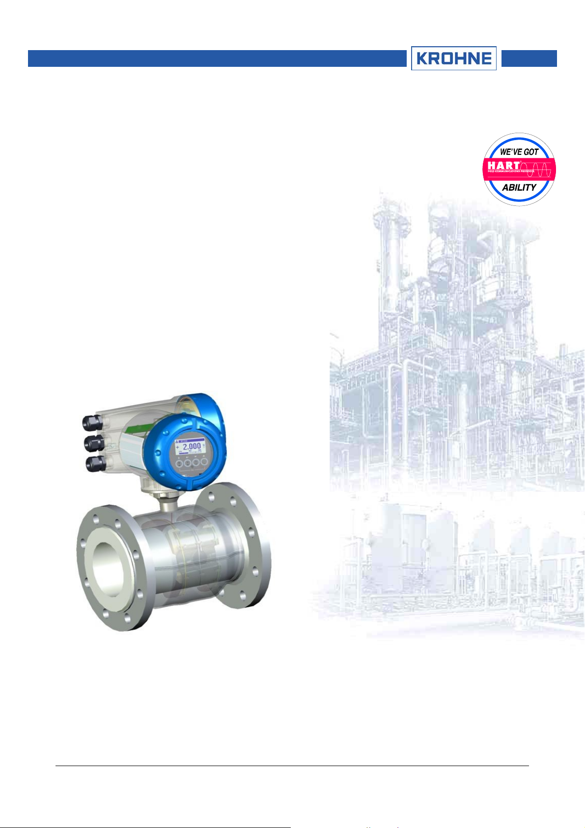
Optiflux IFC300 Converter
with HART Interface
(Dev Rev 2, DD Rev 1)
• HART/Field Communicator 375
• Asset Management Solutions (AMS)
• Process Device Manager (PDM)
• Field Device Tool/Device Type Manager (FDT/DTM)
HART_Suppl_IFC300_V0201.DOC
04/2007
1/23
Page 2

Supplementary Handbook IFC 300 HART, FC375, AMS, PDM, DTM
1 General Information 3
2 IDs and Revision numbers 5
3 Inputs/Outputs and HART Dynamic/Transmitter Variables 6
4 Basic Configuration Parameters 7
5 Field Communicator 375 (FC375) 7
5.1 Installation 7
5.2 Operating 7
6 Asset Management Solutions (AMS) 7
6.1 Installation 7
6.2 Operating 7
7 Process Device Manager (PDM) 8
7.1 Installation 8
7.2 Operating 8
8 Field Device Tool Device Type Manager (FDT DTM) 8
8.1 Installation 8
8.2 Operating 8
9 Attachment: Menu Trees for FC375, AMS and PDM 9
HART_Suppl_IFC300_V0201.DOC
04/2007
2/23
Page 3
Supplementary Handbook IFC 300 HART, FC375, AMS, PDM, DTM
1 General Information
The IFC 300 is a “four-wire” transmitter with 4...20mA current output and HART® capability. Dependent on
jumper setting and/or wiring the current output can operate as active or passive output.
General characteristics of the IFC 300 HART® interface:
• Multidrop Mode is supported
• Burst Mode is not supported
Electrical connection: Refer to section “Electrical connection: outputs and inputs” of the following manual:
• “Handbook IFC 300 signal converter” (KROHNE)
There are two ways of using the HART® communication:
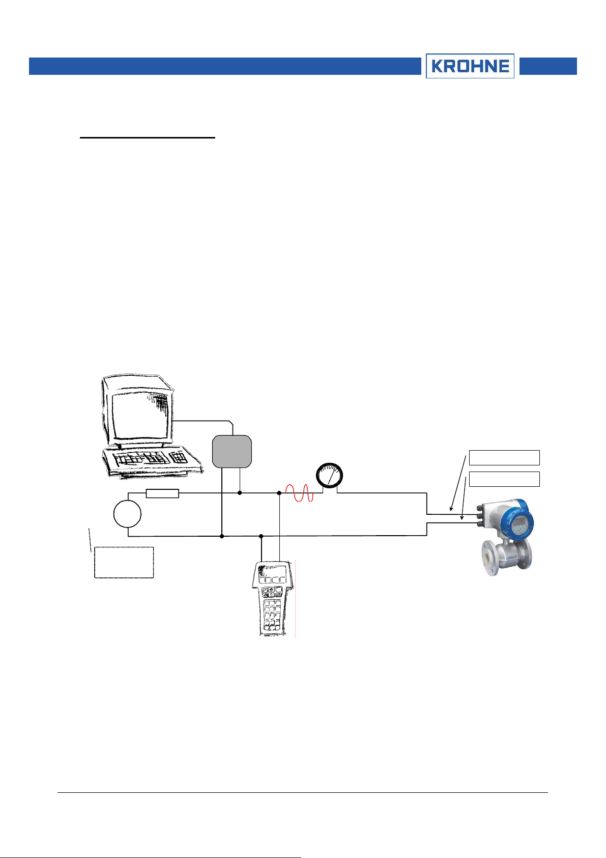
a) As a point-to-point connection between the IFC 300 and the HART master equipment. The instrument' s
current output may be active or passive.
Point-to-Point Analog/Digital Mode
Primary Master
Power
Supply
For slaves with
passive current
output (2 wire)
HART
Modem
HART
≥ 250 Ω
Secondary Master
Analog
mA
420
Terminal A (C)
Terminal A- (C-)
4...20 mA
IFC 300
Addr. 0
HART_Suppl_IFC300_V0201.DOC
04/2007
3/23
Page 4

Supplementary Handbook IFC 300 HART, FC375, AMS, PDM, DTM
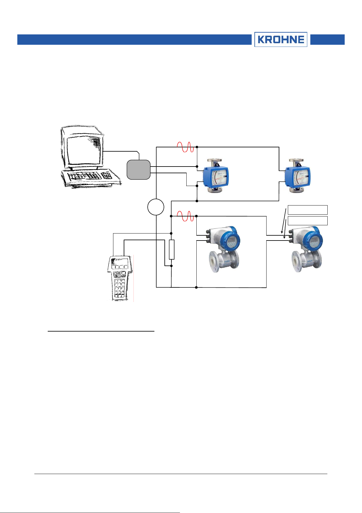
b) As a multipoint connection (multidrop) with up to 15 devices (IFC 300 or other HART® equipment) in
parallel. The instrument's current outputs must be passive.
Multidrop Mode
Primary Master
HART
Modem
HART
Power
Supply
≥ 250 Ω
Terminal A (C)
Terminal A- (C-)
4 mA 4 mA
. . .
Secondary Master Up to 15
Slaves
. . .
IFC 300
Addr. > 0
(passive current output)
IFC 300
Addr. > 0
(passi ve curr ent output)
HART_Suppl_IFC300_V0201.DOC
04/2007
4/23
Page 5
Supplementary Handbook IFC 300 HART, FC375, AMS, PDM, DTM
In case the IFC 300's current output shall work continuously active a 'third wire' is needed to properly
connect it together with two-wire loop powered devices in the same network.
Multidrop Mode (‘three-wire’)
(Connecting two-wire and four-wire devices in the same network)
Primary Master
HART
Modem
HART
4 mA
4 mA
two-wire
loop powered
devices
. . .
Addr. > 0 Addr. > 0
Power
Supply
HART
≥ 250 Ω
4 mA
four-wire
active
source
devices
4 mA
Terminal A (C)
Terminal A- (C-)
Secondary Master
IFC 300
Addr. > 0
. . .
IFC 300
Addr. > 0
2 IDs and Revision numbers
The HART Device Descriptions described in this document have the following IDs and revision numbers:
Manufacturer ID: 69 (0x45)
Device Type: 227 (0xE3)
Device Revision: 2
DD Revision: 1
HART Universal Revision: 5
FC 375 System SW Rev.: ≥ 1.8
AMS Version: ≥ 6.0
PDM Version: ≥ 6.0
For information about Transmitter Revisions and related Device Descriptions refer to the KROHNE HART
Device List.
HART_Suppl_IFC300_V0201.DOC
04/2007
5/23
Page 6
Supplementary Handbook IFC 300 HART, FC375, AMS, PDM, DTM
3 Inputs/Outputs and HART Dynamic/Transmitter Variables
The IFC 300 is available with a choice of output/input assemblies (see details in the section "I/O assemblies
for the outputs and inputs" of the “Handbook IFC 300 signal converter” (KROHNE)):
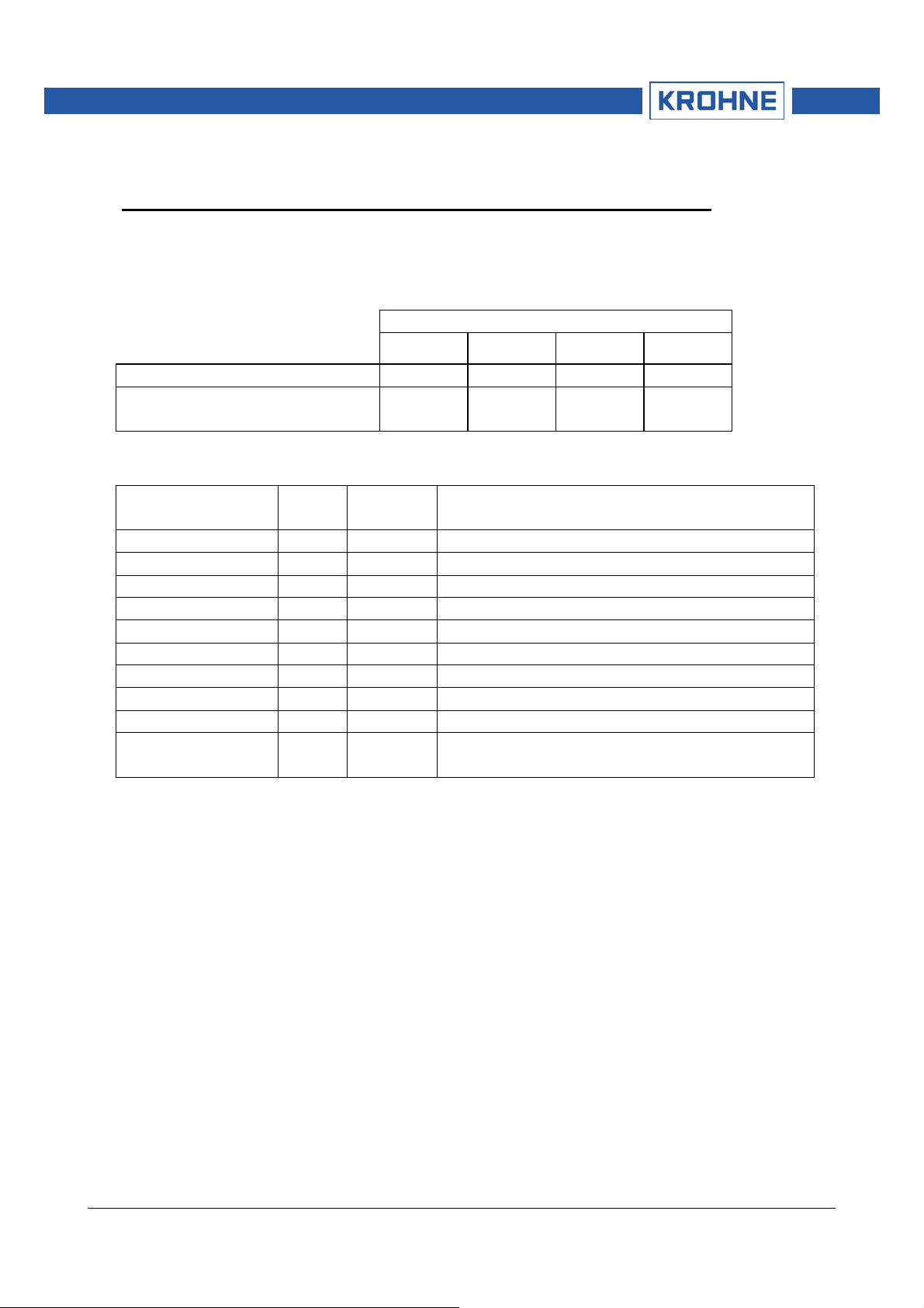
The assignment of the I/O terminals (A, B, C and D) to the HART Dynamic Variables (PV, SV, TV and FV)
depends on the device's I/O option:
HART Dynamic Variables:
PV SV TV FV
Basic I/O terminals: A D - Modular I/O and
EEx–i I/O terminals:
The IFC 300 transmitter handles up to 10 measurement-related HART Transmitter Variables but the sub -set
of available variables depends on the device's I/O option and its configuration:
HART Transmitter
Code
1
Type Notes
Variable
Flow Speed 20 Linear
Volume Flow 21 Linear
Mass Flow 22 Linear
Conductivity 24 Linear
Coil Temperature 23 Linear
Counter 1 (C) 6 Totaliser valid for Basic IO option only
Counter 1 (B) 13 Totaliser valid for Modular I/O and EEx–i I/O options only
Counter 2 (D) 14 Totaliser
Counter 3 (A) 12 Totaliser valid for Modular I/O and EEx–i I/O options only
Diagnosis Value 25 Linear function and validity depend on 'diagnosis value'
1
HART Transmitter Variable Code
To Dynamic Variables which are tied to linear analogue outputs (i.e. current outputs and frequency outputs)
the HART Transmitter Variables are assigned by selecting the 'measurement' (Fct. C2.x.5) for these outputs.
(E.g. when selecting the 'measurement' volume flow for current output A of a device with Basic IO the HART
Transmitter Variable Volume Flow is assigned to the HART Dynamic Variable PV). This implies that only
Transmitter Variables of linear type can be assigned to Dynamic Variables tied to current or frequency
outputs. (A totaliser variable e.g. can't be assigned to PV, the HART current output)
For Dynamic Variables not tied to linear analogue outputs there is no such correlation: Both linear
and totaliser type Transmitter Variables can be assigned (Fct. C4). (Therefore a totaliser variable
e.g. can be assigned to SV, TV and FV unless the respective output is a current or frequency
output.)
C D A B
setting (Fct. C1.3.17)
HART_Suppl_IFC300_V0201.DOC
04/2007
6/23
Page 7

Supplementary Handbook IFC 300 HART, FC375, AMS, PDM, DTM
4 Basic Configuration Parameters
There are some parameters (namely measurement counter 1..3 and diagnosis value selection)
which, after they have been changed, require a warm start of the device e.g. for updating dependent
units parameters, before any other parameters may be written. Dependent on the characteristics
and capabilities of the HART host system (e.g. online-/offline-orientation) these parameters are
treated differently (see details below).
5 Field Communicator 375 (FC375)
5.1 Installation
The IFC 300 HART Device Description has to be installed on the FC375 respectively. Otherwise the user will
work with the instrument as a generic one thus loosing opportunity for entire instrument control.
For installing DDs on the FC375 the ‘Easy Upgrade Programming Utility’ is needed and the FC375 mu st
have a System Card with ‘Easy Upgrade’ option (see details in the ‘375 Field Communicator User’s Manual’).
5.2 Operating
Refer to the IFC 300 Menu Tree FC375 (Attachment A).
The IFC 300 operation via FC375 is made quite close to the manual instrument control via keypad with the
restriction that parameters of the device's "service" menu are not supported and simulation is possible only
for current outputs. The online help of each parameter contains its function number as a reference to the
device’s local display and the “Handbook”.
Parameter protection for custody transfer is the same as on the device's local display. Other specific
protection mechanisms like "password quick setup" and "password setup" are not supported via HART.
The FC375 always creates a “full” configuration for interaction with AMS. Still the FC375 considers only a
partial parameter set (like the “standard configuration” in the HART Communicator HC275) when sending it
to a device.
Basic Configuration Parameters:
In online mode the counter measurement and diagnosis value settings can be changed with the
corresponding methods located in the menu tree below the related parameter. When editing an offline
configuration these parameters are read only, however they are written to the device when sending an offline
configuration
6 Asset Management Solutions (AMS)
6.1 Installation
If the IFC 300 Device Description is not already installed on the AMS System a so called Installation Kit IFC
300 HART AMS is needed (available as download from KROHNE ‘Download Center’ on the internet or on
floppy disk / CD-ROM from KROHNE).
For installing the DD with the Installation Kit refer to the “AMS Intelligent Device Manager Books Online"
section "Basic AMS Functionality /Device Configurations / Installing Device Types / Procedures /Install
device types from media”. Please read also the “readme.txt”, which is also contained in the Installation Kit.
6.2 Operating
Refer to the IFC 300 Menu Tree AMS (Attachment B).
Due to AMS requirements and conventions the IFC 300 operation differs to some extent from operation with
FC375 and via local keypad. Furthermore parameters of the device's "service" menu are not supported and
simulation is possible only for current outputs. The online help of each parameter contains its function
number as a reference to the device’s local display and the “Handbook”.
Parameter protection for custody transfer is the same as on the device's local display. Other specific
protection mechanisms like "password quick setup" and "password setup" are not supported via HART.
Basic Configuration Parameters:
HART_Suppl_IFC300_V0201.DOC
04/2007
7/23
Page 8

Supplementary Handbook IFC 300 HART, FC375, AMS, PDM, DTM
In online mode the counter measurement and diagnosis value settings can be changed with the
corresponding methods located in the "Basic Configuration" menu. When editing an offline configuratio n
these parameters are read only.
7 Process Device Manager (PDM)
7.1 Installation
If the IFC 300 Device Description is not already installed on the PDM System a so called Device Install IFC
300 HART PDM is needed (available as download from KROHNE ‘Download Center’ on the internet or on
floppy disk / CD-ROM from KROHNE).
For installing the DD on PDM V 5.2 refer to the “PDM Manual” section 11.2:”Device Install / Integrating
Devices in SIMATIC PDM with 'Device Install'".
For installing the DD on PDM V 6.0 refer to the “PDM Manual” section 13:”Integrating Devices”.
Please read also the “readme.txt”, which is also contained in the Device Install.
7.2 Operating
Refer to the IFC 300 Menu Tree PDM (Attachment C).
Due to PDM requirements and conventions the IFC 300 operation differs to some extent from operation with
FC375 and via local keypad. Furthermore parameters of the device's "service" menu are not supported and
simulation is possible only for current outputs. The online help of each parameter contains its function
number as a reference to the device’s local display and the “Handbook”.
Parameter protection for custody transfer is the same as on the device's local display. Other specific
protection mechanisms like "password quick setup" and "password setup" are not supported via HART.
Basic Configuration Parameters:
In the PDM offline Parameter Table the counter measurement and diagnosis value settings can be changed
directly and dependent units parameters are updated automatically. However in Online Dialogs of the PDM
Parameter Table an automatic update isn't possible.
8 Field Device Tool Device Type Manager (FDT DTM)
8.1 Installation
If the IFC 300 Device Type Manager is not already installed on the Field Device Tool container a setup is
needed (available as download from KROHNE ‘Download Centre’ on the internet or on CD-ROM from
KROHNE).
For installing the DTM with the setup refer to the setup’s accompanying documentation.
8.2 Operating
The IFC 300 operation via DTM is made quite close to the manual instrument control via keypad. Refer to
the device’s local display and the “Handbook”.
HART_Suppl_IFC300_V0201.DOC
04/2007
8/23
Page 9

Supplementary Handbook IFC 300 HART, FC375, AMS, PDM, DTM
9 Attachment: Menu Trees for FC375, AMS and PDM
Attachment A
IFC 300 HART Menu Tree FC375
1 dynamic
variables
1 measured values
2 in/outputs
1 volume föw
2 mass flow
3 flow speed
4 conductivity
5 coil temperature
6 counter 1
7 counter 2
8 counter 3
Opt
Opt
Opt
9 diagnosi svalue
Opt
1 A
2 % range A
3 B
4 % range B
5 C
6 % range C
7 D
8 % range D
Opt
Opt
Opt
Opt
Opt
Opt
Opt
Opt
2 quick setup
3 test
4 setup
1 language
2 tag
3 reset
4 analog out puts
5 digital outputs
1 simulation
2 informati on
2,3,4
1 reset errors
2 reset counter1
3 reset counter2
4 reset counter3
1 measureme nt A/C
Cust
2 unit
3 range min A/C
4 range max A/C
5 lfc threshold
6 lfc hysteresis
7 time constant
1 measureme ntD
2 pulse val. unit
3 value p. pulse D
4 lfc threshold
5 lfc hysteresis
Cust
Cust
Opt, Cust
Cust
Cust
Cust
Cust
Cust
Cust
Opt, Cust
Opt, Cust
Opt, Cust
Opt, Cust
Opt, Cust
1 simul. current/frequencyA
2 simul. current/frequencyB
3 simul. current C
4 simul. frequency D
Opt
Opt
1 C number
2 info process input
3 info device
4 info display
Opt
Opt
Designations:
Opt
Optional, dependent on device
implementation / configuration
Rd
Read-only
Cust
Custod y Lock protec te d
Loc
Local FC375,
affects only FC375 views
HART_Suppl_IFC300_V0201.DOC
04/2007
KROHN E IFC 300 HA 45e3020 1 (1/4)
04/06
9/23
Page 10

Supplementary Handbook IFC 300 HART, FC375, AMS, PDM, DTM
1 dynamic
variables
2 quick setup
3 test
4 setup
IFC 300 HART Menu Tree FC375
1 calibration
1
1 processinput
2 filter
1 autom. zero calib.
2 zero set
3 size
4 GK selection
5 GK / GKH
6 GKL
7 coil resist. Rsp
8 density
Cust
Cust
Cust
Opt, Cust
Opt, Cust
Cust
Cust
9 target conductivity
10 EF electr. factor
11 num. of electr odes
12 field frequency
13 select settling
14 sett lingtime
15 line frequency
1 limitation min
2 limitation max
3 flow direction
4 time constant
5 pulse filter
6 pulse width
7 pulse limitation
8 noise filter
9 noise level
10 n. suppression
11 lfc threshold
12 lfc hysteresis
Cust
Cust
Opt, Cust
Cust
Cust
Cust
Cust
Cust
Opt, Cust
Opt, Cust
Cust
Opt, Cust
Opt, Cust
Cust
Cust
Cust
Cust
Cust
Designations:
Opt
Optional, dependent on device
implementation / configuration
Rd
Read-only
Cust
Custod y Lock protec te d
Loc
Local FC375,
affects only FC375 views
2 I/O
3 I/O Counter
4 I/O HART
5 device
3 self test
4 information
5 sensor limits
3,4
1 empty pipe
2 limit empty pipe
3 full pipe
4 limit full pipe
5 linearity
6 gain
7 coil current
8 flow profile
Cust
Opt, Cust
Opt, Cust
Cust
Cust
Cust
Cust
9 limitflow profil e
10 electrodenoise
11 limit elect. noise
12 settlingof field
13 diagnosisvalue
14 select diagnosis
1 liner
2 elect r ode material
3 serialno. sensor
4 V no. sensor
Rd
5 sensor electr. info
1 volumeflow
2 massflow
3 flow speed
4 conductivity
5 coil temperature
Opt, Cust
Opt, Cust
Cust
Opt, Cust
Cust
Rd
Rd
1 upper snsr limit
2 lower snsr limit
3 minimum span
KROHN E IFC 300 HA 45e3020 1 (2/4)
04/06
Rd
Rd
Rd
HART_Suppl_IFC300_V0201.DOC
04/2007
10/23
Page 11

Supplementary Handbook IFC 300 HART, FC375, AMS, PDM, DTM
1 dynamic
variables
2 quick setup
3 test
4 setup
Designations:
Opt
Optional, dependent on device
implementation / con figuration
Rd
Read-only
Cust
Custod y Loc k protect ed
Loc
Local FC375,
affects only FC375 views
IFC 300 HART Menu Tree FC375
1
1 processinput
2 I/O
3 I/O Counter
4 I/O HART
5 device
2
1 hardware
2 A
3 B
4 C
5 D
1 counter1
2 counter2
3 counter 3
4
1 terminals A
2 terminals B
3 terminals C
4 terminals D
current output
1 range0%
2 range100%
3 ext. range min
4 ext. range max
5 error current
6 errorcondition
7 meas urement
8 rangemin
9 rangemax
10 pol a rity
11 limi tmin
12 limitmax
13 lfcthreshold
14 lfchysteresis
15 tim e constant
16 spe c ial functio n
17 rc threshold
18 rc hysteresis
19 information x
frequencyoutput
1 pulse shape
2 pulse width
3 100% pulse rate
4 meas urement
5 rangemin
6 rangemax
7 polarity
8 limi tmin
9 limi tmax
10 lfcthreshold
11 lfchysteresis
13 tim e constant
14 invert signal
15 spe c ial functio n
16 phaseshift w. B
17 information x
1 function
2 meas urement
Opt
3 select measurement
4 lfc threshold
5 lfchysteresis
6 time constant
7 presetvalue
8 resetcounter x
9 set counter x
10 information
Cust
Cust
Cust
Cust
Opt
:
Cust
Cust
Cust
Cust
Cust
Cust
Cust
Cust
Cust
Cust
Cust
Cust
Cust
Cust
Cust
Cust
Opt, Cust
Opt, Cust
pulse output
1 pulse shape
2 pulse width
3 max pulse rate
4 meas urement
5 pulse value unit
6 value p. pulse
7 pola rity
8 lfc threshold
9 lfchysteresis
10 time constant
11 invert signal
12 special function
13 phaseshift w. B
14 informatio nx
statusoutput
1 mode
2 outpu tA
output B
Opt
:
Cust
Cust
Cust
Cust
Cust
Cust
Cust
Cust
Cust
Cust
Cust
Cust
Opt, Cust
Opt, Cust
output C
output D
3 invert signal
4 informationx
limit switch
1 meas urement
2 threshold
3 hysteresis
4 pola rity
5 time constant
6 invert signal
7 informationx
controlinput
1 mode
2 invert signal
3 informationx
Cust
Opt, Rd
Opt, Cust
Opt, Cust
Opt, Cust
Opt, Cust
Opt, Cust
Opt, Cust
Opt, Cust
KROHNE IFC 300 HA 45e30201 (3/ 4)
04/06
Opt
:
Cust
Cust
Cust
Cust
Cust
Cust
Cust
Cust
Cust
Cust
Opt, Cust
Opt, Cust
Opt
:
Opt
Opt
Opt
Opt
Opt
:
Opt
:
Cust
HART_Suppl_IFC300_V0201.DOC
04/2007
11/23
Page 12

Supplementary Handbook IFC 300 HART, FC375, AMS, PDM, DTM
1 dynamic
variables
2 quick setup
3 test
4 setup
1
1 processinput
2 I/O
3 I/O Counter
4 I/O HART
5 devi ce
IFC 300 HART Menu Tree FC375
2
3
Rd
1 PV is
2 SV is
3 TV is
4 4V is
5 D/A trim
Cust
6 apply values
1 deviceinfo
2 display
3 1. meas. page
4 2. meas. page
5 graphic page
Cust
1 tag
2 C number
3 deviceserial no.
4 electronicserial no.
5 infodevice
1 language
2 default display
3 infodisplay
1 select range
2 rang ecentre
3 range+/4 time scale
1 funct ion
2 meas u rem. 1. l ine
3 rang emin
Rd
4 rang emax
5 limitation min
6 limitation max
7 lfc threshold
8 lfchystereis
9 time constant
Cust
10 format 1. line
11 measurem. 2. line
12 format 2. line
13 measurem. 3. line
14 format 3. line
Cust
Cust
Cust
Cust
Cust
Cust
Cust
Cust
Designations:
Opt
Optional, dependent on device
implementation / configuration
Rd
Read-only
Cust
Custody Lock protected
Loc
Local FC375,
affects only FC375 views
3 specialfunctions
4 units (device)
5 HART
6 circuit board info
1 list errors
2 reset errors
3 warmstart
1 volume flow
2 massflow
Cust
Cust
3 flowspeed
4 conductivity
5 temp erature
Cust
6 volu me
Cust
7 mass
Cust
8 density
1 address
2 message
3 descriptor
4 units (HART)
5 formats (HART)
6 device information
8 preambles
9 mast er reset
10 prepar e download
1 volume flow
2 massflow
3 flowspeed
4 conductivity
5 temp erature
6 count er 1
7 count er 2
8 count er 3
Opt
9 diagnosis value
1 manufacturer
2 model
3 device ID
Rd
Rd
Rd
3 tag
4 date
5 writ eprotect
Rd
6 final asse mbly no.
7 sensor serial no.
8 revision nos.
1 univ ersal re v.
2 device rev.
3 software rev.
4 hardware rev.
1 request preams
Rd
Rd
Rd
Rd
Rd
2 response preams
KROHNE IFC 300 HA 45e30201 (4/4)
04/06
HART_Suppl_IFC300_V0201.DOC
04/2007
12/23
Page 13

Supplementary Handbook IFC 300 HART, FC375, AMS, PDM, DTM
Attachment B
Configure
Compare
Clear Offline
-----------------------------------
Status/Conditions
Process V ariables
Scan Device
-----------------------------------
Calibration Management
Diagnostics and Test
Calibrate
Reset
Basic Configuration
----------------------------------Rename
Unassign
Assign / Replace
----------------------------------Audit Trail
Record M anual Event
Drawings / Notes ...
Help ...
Designations:
Opt
Optional, dependent on devi ce
implementation / configuration
Rd
Read-only
Cust
Custody Lock prote ct ed
Loc
Local AMS, affects only AMS views
IFC 300 HART Menu Tree AMS
quick setup
device:
•language
•tag
2,3
pulse output D:
•measurement D
• pulse val ue unit
• value p. puls e D
• lfc threshold
4
• lfc hysteresis
5
input calibration
5
•zero set
•size
• GK selection
• GK / GKH
•GKL
•coil resist. Rsp
•density
input filter
•limitation max
• limitation min
• flow direction
• time constant
•pulse filter
• pulse widt h
• pulse limitation
self test / info
self test:
•empty pipe
• limit empty pipe
• full pipe
•limit full pipe
•linearity
•gain
• coil current
• flow pr of i le
• limit flow profile
Opt, Cust
Opt, Cust
Opt, Cust
Opt, Cust
Opt, Cust
Cust
Cust
Cust
Opt, Cust
Opt, Cust
Cust
Cust
Cust
Cust
Cust
Cust
Cust
Cust
Cust
Opt, Cust
Opt, Cust
Opt, Cust
Cust
Cust
Cust
Cust
Opt, Cust
current outpu t A/C:
•measurement A/C
•unit A/C
•range A/C max
•range A/C min
•time constant A/C
• lfc threshold A/C
• lfc hysteresis A/C
• target conductivity
• EF electrode factor
• num. of elect rodes
• field frequency
• select settling
•settling time
• line frequency
• noise filter
•noise level
• noise suppression
• lfc threshold
• lfc hysteresis
self test:
• electrode noise
• limit elec t. n o ise
•settling of field
• diagnosis value
information:
•liner
•electrode material
• serial no. sensor
• V no. sensor
sensor
volume flow sensor limits:
Cust
Cust
Cust
Cust
Cust
• upper sensor limit
• lower sensor limit
• minimum span
Cust
mass flow sensor limits:
...
Cust
flow speed sensor lim it s :
...
cond u ctivity sensor limits:
...
coil temperature snsr limits:
...
Cust
Cust
Cust
Cust
Opt, Cust
Cust
Cust
Cust
Opt, Cust
Cust
Cust
Cust
Opt, Cust
Cust
Rd
Rd
Rd
KROHNE IFC 300 HA 45e30201 (1/5)
04/06
Rd
Rd
Rd
HART_Suppl_IFC300_V0201.DOC
04/2007
13/23
Page 14

Supplementary Handbook IFC 300 HART, FC375, AMS, PDM, DTM
IFC 300 HART Menu Tree AMS
I/O terminals A/B/C /D
•terminals
Opt
:
Cust
Cust
Cust
Cust
Cust
Cust
Cust
Cust
Cust
Opt
:
Cust
Cust
Cust
Cust
Cust
Cust
Cust
Cust
Opt
:
Cust
Cust
Cust
Cust
• range 100%
•range 0%
•ext. range max
•ext. range min
•error current
• error condition
• special function
• rcthreshold
•rchysteresis
• pulse shape
• pulse width
• 100% pulse rate
•invert signal
• special function
• phase shift wrt. B
• pulse value unit
• value p. pulse
• pulse shape
• pulse width
• max pulse rate
•invert signal
• special function
• phase shift wrt. B
Opt
:
•output A
•output B
•output C
•output D
Cust
Cust
Cust
Cust
Cust
Cust
Cust
Opt, Cust
Opt, Cust
Cust
Cust
Cust
Cust
Opt, Cust
Opt, Cust
Cust
Cust
Cust
Cust
Cust
Cust
Opt, Cust
Opt, Cust
Opt
Opt
Opt
Opt
•invert signal
Opt
:
•invert signal
Opt
:
Cust
•invert signal
Configure
Compare
Clear Offline
-----------------------------------
Status/Conditions
Process Variables
Scan Device
-----------------------------------
Calibration Management
Diagnostics and Test
Calibrate
Reset
Basic Configuration
----------------------------------Rename
Unassign
Assign / Replace
----------------------------------Audit Trail
Record Manual Event
Drawings / Notes .. .
Help ...
1,3
4
5
5
current output
• measurement
• limitation max
• limitation min
• time consta nt
•polarity
• lfc threshold
• lfch ysteresis
• range max
•range min
frequency out pu t
• measurement
• limitation max
• limitation min
• time consta nt
•polarity
• lfc threshold
• lfch ysteresis
• range max
•range min
pulse output
• measurement
• time consta nt
•polarity
• lfc threshold
• lfch ysteresis
status output
•mode
limit switch
• measurement
• time consta nt
•polarity
•threshold
•hysteresis
control input
•mode
Designations:
Opt
Optional, dependen t on d ev ice
imple mentation / configuration
Rd
Read-only
Cust
Custody Lock protected
Loc
Local AMS, affects only AMS view s
HART_Suppl_IFC300_V0201.DOC
04/2007
counter
counter 1:
• function
• measurement
• lfc threshold
• lfch ysteresis
• time consta nt
•preset value
Opt
Cust
Opt, Cust
Opt, Cust
Opt, Cust
Opt, Cust
Opt, Cust
counter 2:
• function
Cust
•measurement
•lfcthreshold
• lfchysteresis
• time consta nt
•preset value
Opt, Cust
Opt, Cust
Opt, Cust
Opt, Cust
Opt, Cust
counter 3
•function
•measurement
• lfcthreshold
• lfchysteresis
• time cons ta nt
•preset value
:
Cust
Opt, Cust
Opt, Cust
Opt, Cust
Opt, Cust
Opt, Cust
KROHNE IFC 300 HA 45e30201 (2/5)
04/06
14/23
Page 15

Supplementary Handbook IFC 300 HART, FC375, AMS, PDM, DTM
Configure
Compare
Clear Offline
-----------------------------------
Status/Conditions
Process Variables
Scan Device
-----------------------------------
Calibration Management
Diag n ostics a nd Test
Calibrate
Reset
Basic Configuration
----------------------------------Rename
Unassign
Assign / Replace
----------------------------------Audit Trai l
Record Manual E vent
Drawings / Notes ...
Help ...
Designations:
Opt
Optional, dependent on device
implemen tation / co n f igu ration
Rd
Read-only
Cust
Cust od y Lock pr ot e ct e d
Loc
Local AMS, affect s only AMS vi e ws
IFC 300 HART Menu Tree AMS
device
device info:
•tag
• C number
• device serial no.
• electronic serial no.
display:
• language
• default display
1. me as./gra ph. pa ge / 2. meas page
1,2
• function
• measurem. 1. line
•limitation max
•limitation min
• time constant
4
•lfcthreshold
•lfchysteresis
5
• range ma x
•range min
•format 1. line
HART
5
identification:
• manufacturer
•model
• device ID
•address
•tag
•date
•message
• descriptor
•write protect
• final assembly no.
• senso r s erial no.
HART units
display formats:
• volume flow
•mass flow
• flow speed
• conductivity
•temperature
• counter 1
• counter 2
• counter 3
• diagnosis value
Rd
Rd
Rd
Cust
Cust
Cust
Cust
Cust
Rd
Rd
Rd
revision numbers:
• universal rev.
•device rev.
• software rev.
• hardware re v.
preambles:
• request preambles
Rd
Loc
Loc
Loc
Loc
Loc
Loc
Loc
Opt, Loc
Opt, Loc
• response preambles
units:
• volume flow
•mass flow
Cust
Cust
• flow speed
• conductivity
•temperature
•volume
•mass
•density
•measurem. 2. line
•format 2. line
•measurem. 3. line
•format 3. line
Cust
Cust
Cust
Cust
Cust
graphic page:
• select range
•range centre
•range +/-
• time scale
Rd
Rd
Rd
Rd
Rd
units:
• volume flow
•mass flow
• flow speed
• conductivity
•temperature
• counter 1
• counter 2
• counter 3
Opt
Cust
Cust
dynamic variables settings:
Rd
•PV is
•SV is
•TV is
•4V is
KROHNE IFC 300 HA 45e30201 (3/5)
04/06
HART_Suppl_IFC300_V0201.DOC
04/2007
15/23
Page 16

Supplementary Handbook IFC 300 HART, FC375, AMS, PDM, DTM
IFC 300 HART Menu Tree AMS
Failure (d e v ice)
• F error in device
•F IO1
•F parameter
•F IO2
• F configu ra t ion
•F display
• F sensor electronic
• F sensor global
• F sensor local
• F over range A (current)
• F over ra nge B (current)
• F over ra nge C (current)
• F over range A (pulse)
• F over range B (pulse)
• F over range D (pulse)
• F active settings
• F factory se tt in g s
• F backup 1 settings
• F backup 2 settings
• S field coil broken
• S field coil b ridged
• S field current deviation
• S field frequency too high
• S electronic tempe ra tu re
• S coil temp er atu r e
• S overflow counter 1
• S overflow counter 2
• S overflow counter 3
• S backplane invalid
• F field curr ent loca l
• F current ou tput A
• F current ou tput B
• F current ou tput C
• F software user interface
• F hardware settings
• F hardwar e detection
• F RAM/ROM error IO 1
• F RAM/ROM error IO 2
Check req. & Information
check reque st:
• C checks in progress
•C test sensor
information:
• I counter 1 stopped
• I counter 2 stopped
• I counter 3 stopped
• I power fail
• I control in pu t A a ctive
• I control input B active
• I over ra nge display 1
• I over ra nge display 2
• I backpl ane sensor
• I backpl ane settings
• I backplane differe nce
• I optic al interface
Configure
Compare
Clear Offline
-----------------------------------
Status/Conditions
Process Variables
Scan Device
-----------------------------------
Calibration Management
Diagnosti cs and Test
Calibrate
Reset
Basic Confi guration
----------------------------------Rename
Unassign
Assign / Replace
----------------------------------Audit Trail
Record Manual Event
Drawings / Notes ...
Help ...
Overview
Standard:
• Primary variable out of
limits
• Non-primary variable out
of limi ts
• Primary variable analog
1,2,3
output saturated
• Primary variable analog
output fixed
•Cold start
• Configuration chan ged
• Field dev ic e m a lfu n ction
5
Failure (application)
• F application error
• F empty pipe
• F flow rate too hig h
5
• F field frequency too high
•F DC offset
• F open circuit A
• F open circuit B
• F open circuit C
Out of specification
• S out of spec ification
• S pipe not fu ll
• S empty pipe
• S linearity
• S flow prof ile
•S electrode noise
•S gain error
•S electrode symmetry
Designations:
Opt
Optional, dependent on device
implementation / configuration
Rd
Read-only
Cust
Custody Lock protected
Loc
Local AMS, affects only AMS views
HART_Suppl_IFC300_V0201.DOC
04/2007
KROHNE IFC 300 HA 45e30201 (4/5)
04/06
16/23
Page 17

Supplementary Handbook IFC 300 HART, FC375, AMS, PDM, DTM
IFC 300 HART Menu Tree AMS
Configure
Compare
Clear Offline
-----------------------------------
Status/Conditions
Process Variables
Scan Device
-----------------------------------
Calibration Management
Diagnostics and Test
Calibrate
Reset
Basic Confi guration
----------------------------------Rename
Unassign
Assig n / Replace
----------------------------------Audit Trail
Record Manual Eve nt
Drawings / Notes ...
Help ...
proces s values:
•volume flow
•mass flow
•flow speed
1,2,3
• conductivity
• coil temperature
• diagnosis value
Device:
4
Rd
•tag
• descriptor
Rd
Simulation current o utput A/C
Simulation current/frequency output A
Simulation current/frequency output B
Simulatio n frequency outp ut D
Circuit Board Info
Autom. zero calibration
Cust
D/A trim
Apply values
Cust
Reset Errors
Reset Configuration Changed Flag
Master Reset
Warmstart
Reset Counter 1
Set Counter 1
Reset Counter 2
Set Counter 2
Reset Counter 3
Set Counter 3
Cust
Cust
Cust
Cust
Opt, Cust
Opt, Cust
counter:
•counter 1
•counter 2
•counter 3
Opt
HART:
•Polling Address
• Device ID
Opt, Cust
Opt, Cust
Cust
Opt
Opt
Opt
Rd
Rd
Opt, Cust
Opt, Cust
outputs:
Opt
•A
•% range A
Opt
•B
•% range B
Opt
•C
•% range C
Opt
•D
•% range D
Opt
Opt
Opt
Opt
Designations:
Opt
Optional, dependent on device
impl ementation / configurati on
Rd
Read-only
Cust
Custod y Lo ck protected
Loc
Local AMS, affects on l y AMS views
HART_Suppl_IFC300_V0201.DOC
04/2007
Select Measurement Counter 1
Select Measurement Counter 2
Select Measurement Counter 3
Select Diagnosi s Value
Opt
KROHNE IFC 300 HA 45e30201 (5/5)
04/06
17/23
Page 18

Supplementary Handbook IFC 300 HART, FC375, AMS, PDM, DTM
Attachment C
Communication Path
----------------------------------Load To Device
Load To PG/PC
----------------------------------Set Address
-----------------------------------
Test
Reset
IFC 300 HART Menu Tree PDM
Menu Bar
File Device View Options Help
2,3
Test
• simuation. current/frequency A
• simuation current/freque ncy B
• simuation current C
Opt, Cust
• simuation frequency D
Reset
• <rese t errors>
• <reset configuration changed flag>
•<master reset>
•<warmstart>
Opt, Cust
Opt, Cust
Opt, Cust
• <rese t counter 1>
• <set counter 1>
• <rese t counter 2>
• <set counter 2>
• <rese t counter 3>
• <set counter 3>
Cust
Cust
Cust
Cust
Opt, Cust
Opt, Cust
Calibration
-----------------------------------
Parameter Protection
-----------------------------------
HART
Designations:
Opt
Optiona l, dependent on device
implementation / configuration
Rd
Read-only
Cust
Custod y L o ck protected
Loc
Local PDM, affects only PDM views
Calibration
• automat ic z er o calibrat ion
•D/A trim
• apply values
Cust
Cust
HART
preambles
• request preambles
Rd
• response preambles
Cust
dynamic variables settings
Rd
•PV is
•SV is
•TV is
•4V is
KROHNE IFC 300 HA 45e30201 (1/6)
04.06
HART_Suppl_IFC300_V0201.DOC
04/2007
18/23
Page 19

Supplementary Handbook IFC 300 HART, FC375, AMS, PDM, DTM
IFC 300 HART Menu Tree PDM
Menu Bar
1
File Device View Options Help
Counters
• counter 1
• counter 2
• counter 3
Opt
Opt
Opt
Display
Yt Diagram
Measured Values
• volume fl ow
•mass flow
• flow speed
• conductivity
• coil temperature
• diagnos is va lue
• device status
Y t Diagram
• volume flow
•mass flow
Outputs
Device Status
Circuit B o ard Info
----------------------------------Toolbar
Status Bar
----------------------------------Update
Designations:
Opt
Optiona l, dependent on device
implementation / configuration
Rd
Read-only
Cust
Custod y L o ck protected
Loc
Local PDM, affects only PDM views
Outputs
current/frequenc y o. A
• measured value
Opt
•A
• % range A
current/frequenc y o. B
• measured value
Opt
•B
• % range B
3
Opt
:
Opt
Opt
Opt
Opt
current output C
• measured value
Opt
•C
• % range C
Opt
:
frequency output D
• measured value
Opt
•D
• % range D
Opt
:
Opt
Opt
Opt
:
Opt
Opt
KROHNE IFC 300 HA 45e30201 (2/6)
04.06
HART_Suppl_IFC300_V0201.DOC
04/2007
19/23
Page 20

Supplementary Handbook IFC 300 HART, FC375, AMS, PDM, DTM
IFC 300 HART Menu Tree PDM
Menu Bar
1
File Device View Options Help
Display
Yt Diagram
Outputs
Device Status
2
device
• C number
• device serial no.
• electronic serial no.
HART:
•tag
• manufacturer
•model
•device ID
failure
failure ( de v ice):
• F error in device
•F IO1
•F parameter
•F IO2
• F configuration
•F display
• F sensor e lectronic
• F sensor global
standard
Rd
• univer sal revision
•device revision
Rd
• software revision
Rd
• hardware revision
Rd
•date
• write protect
• final assembly no.
Rd
Rd
Rd
• sensor serial no.
failure (device):
•F sensor local
• F field cur r ent local
• F current outpu t A
• F current outpu t B
• F current outpu t C
• F software us er interf ac e
•F hardware settings
•F hardware detection
• F RAM/ROM error IO 1
• F RAM/ROM error IO 2
Rd
overview:
Rd
• Primary variable out of limits
Rd
• Non-pr imary var ia ble out of limits
Rd
• AO outsi d e th e operat in g range lim its
Rd
• Analog Output in fixed mode
•Cold start
Rd
• Configuration changed
Rd
• Field device malfunction
failure (application):
• F application error
• F empty p ip e
• F flow rate too high
• F field frequenc y too high
•F DC offset
•F open circuit A/B/C
• F over ran g e A/B/C (cu rr ent)
• F over range A/B/D (pulse)
• F active settings
• F factor y settings
• F backup 1/2 settings
Circuit B o ard Info
----------------------------------Toolbar
Status Bar
----------------------------------Update
Designations:
Opt
Optiona l, dependent on device
implementation / configuration
Rd
Read-only
Cust
Custod y L o ck protected
Loc
Local PDM, affects only PDM views
HART_Suppl_IFC300_V0201.DOC
04/2007
off-spe c / ch e c ks / in f o
out of sp ecif i ca tion :
• S out of spe c if ication
• S pipe not full
• S empty p ip e
• S linear ity
• S flow profile
• S electrode noise
• S gain error
• S electrode symmetry
• S field co il broken
• S field co il bridged
• S field current deviation
• S fie l d frequ ency too high
• S electronic temperature
• S coil tem p er ature
• S overflow counter 1
• S overflow counter 2
• S backplane invalid
• S overflow counter 3
check request:
• C checks in progress
• C test sensor
information:
• I counter 1 stopped
• I counter 2 stopped
• I power fail
• I control input A active
• I contro l input B act iv e
• I over range display 1
• I over range display 2
• I backplane sen s or
• I backplane settings
• I backplane dif ference
• I optical interface
• I counter 3 stopped
KROHNE IFC 300 HA 45e30201 (3/6)
04.06
20/23
Page 21

Supplementary Handbook IFC 300 HART, FC375, AMS, PDM, DTM
identification
operation unit
device
-----------------------------------
input
calibration
filter
self test
information
measuring limits
-----------------------------------
IO
Opt
A
Opt
B
Opt
C
Opt
D
counter 1
counter 2
counter 3
-----------------------------------
human interface
local display
units (device)
units (HART)
formats (HART)
IFC 300 HART Menu Tree PDM
Parameter Table
identification
operation unit
•tag
•descriptor
• message
device
• C number
• device serial no.
• electronic serial no.
• manufacturer
•model
• device ID
• universal revi sion
• device revision
• software revision
•hardware revision
Rd
Rd
Rd
Rd
Rd
Rd
Rd
Rd
Rd
Rd
•date
•final assembly no.
5
• sensor serial no.
input
calibration
•zero set
•size
• GK selection
Opt
• GK/GKH
•GKL
•density
• target conductivity
6
• EF electrode factor
• nu m be r of e le ctrod e s
• field frequency
• select settling
• settling time
• line frequency
filter
• limitation min
• limitation max
• flow d ire c t ion
• time constant
•pulse filter
•pulse width
• pulse lim it ation
• noise filter
• noise level
• noise suppression
• lfc threshold
• lfc hysteresis
Cust
Cust
Cust
Opt,
Cust
Opt,
Cust
Cust
Cust
Cust
Opt,
Opt,
Opt,
Cust
Cust
Cust
Cust
Cust
Cust
Cust
Cust
Cust
Cust
Opt,
Cust
Cust
Opt,
Cust
Cust
Cust
input
...
self test
• empty pipe
• limit empty pip e
• full pipe
• limit full pipe
• linearity
•gain
Cust
Cust
Cust
• coil cu rrent
• flow pro f il e
• limit f low profile
• electrode noise
• limit e le ct. noise
• settling of field
• diagn o sis value
information
• liner
• electrode material
• serial no. sensor
• V no. sensor
measuring limits
volume flow
• upper sensor limit
• lower sensor limit
• m inimum span
mass flow
•...
flow speed
•...
conductivity
•...
coil temperature
•...
...
Cust
Opt,
Cust
Opt,
Cust
Cust
Cust
Opt,
Cust
Cust
Opt,
Cust
Cust
Rd
Rd
Rd
Rd
Rd
Designations:
Opt
Optiona l, dependent on device
implementation / configuration
Rd
Read-only
Cust
Custod y L o ck protected
Loc
Local PDM, affects only PDM views
HART_Suppl_IFC300_V0201.DOC
04/2007
...
KROHNE IFC 300 HA 45e30201 (4/6)
04.06
21/23
Page 22

Supplementary Handbook IFC 300 HART, FC375, AMS, PDM, DTM
identification
operation unit
device
-----------------------------------
input
calibration
filter
self test
information
measuring limits
-----------------------------------
IO
Opt
A
Opt
B
Opt
C
Opt
D
counter 1
counter 2
counter 3
Opt
-----------------------------------
human interface
local display
units (device)
units (HART)
formats (HART)
Designations:
Opt
Optiona l, dependent on device
implementation / configuration
Rd
Read-only
Cust
Custod y L o ck protected
Loc
Local PDM, affects only PDM views
IFC 300 HART Menu Tree PDM
Parameter Table
4
4
6
output
•terminals A
•terminals B
•terminals C
•terminals D
A/B/C/D
current out put
•range 0%
• range 100%
• ext. range min
• ext. range max
• error current
• error condition
•measurement
•range min
•range max
• polarity
• limit min
• limit max
• lfcthreshold
• lfchysteresis
• time con stant
• special function
•rcthreshold
•rchysteresis
frequency output
•pulse shape
•pulse width
• 100% puls e rate
•measurement
•range min
•range max
• polarity
• limit min
• limit max
• lfcthreshold
• lfchysteresis
• time con stant
•invert signal
• special function
•phase shift wrt. B
pulse output
•pulse shape
•pulse width
• max pulse rate
•measurement
• pulse value unit
• value p. pulse
• polarity
• lfcthreshold
• lfchysteresis
• time con stant
•invert signal
• special function
•phase shift wrt. B
...
Cust
Cust
Cust
Cust
Opt
Opt
:
Cust
Cust
Cust
Cust
Cust
Cust
Cust
Cust
Cust
Cust
Cust
Cust
Cust
Cust
Cust
Cust
Opt,
Cust
Opt,
Cust
Opt
:
Cust
Cust
Cust
Cust
Cust
Cust
Cust
Cust
Cust
Cust
Cust
Cust
Opt,
Cust
Opt,
Cust
Opt
:
Cust
Cust
Cust
Cust
Cust
Cust
Cust
Cust
Cust
Cust
Opt,
Cust
Opt,
Cust
...
status out put
•mode
•output A
•output B
•output C
•output D
Opt
:
Opt
Opt
Opt
Opt
•invert signal
limit switch
Opt
:
•measurement
• threshold
•hysteresis
• polarity
•time constant
•invert signal
Opt
control i nput
•mode
:
Cust
•invert signal
counter 1/2/3
• function
•measurement
• lfcthreshold
• lfch ysteresis
•time constant
• preset va lu e
Opt
Cust
Opt
Opt
Opt
Opt
Opt
KROHNE IFC 300 HA 45e30201 (5/6)
04.06
HART_Suppl_IFC300_V0201.DOC
04/2007
22/23
Page 23

Supplementary Handbook IFC 300 HART, FC375, AMS, PDM, DTM
identification
operation unit
device
-----------------------------------
input
calibration
filter
self test
information
measuring limits
-----------------------------------
IO
Opt
A
Opt
B
Opt
C
Opt
D
counter 1
counter 2
counter 3
-----------------------------------
human interface
local display
units (device)
units (HART)
formats (HART)
IFC 300 HART Menu Tree PDM
Parameter Table
human interface
local dis p la y
4
4
5
Opt
•language
•default display
1./2. measurement page
• function
•measurement 1. line
•range min
•range max
Cust
Cust
Cust
Cust
• limitation min
• limitation max
• lfc threshold
• lfc hysteresis
• time constant
• format 1. line
•measurement 2. line
• format 2. line
•measurement 3. line
• format 3. line
Cust
Cust
graphic pa ge
• select range
•range centre
•range +/-
•time scale
units (device)
• volume flow
•mass flow
Cust
Cust
• flow speed
• conductivity
•temperature
• volume
•mass
•density
Cust
Cust
Cust
units (HART)
• volume flow
•mass flow
• flow speed
• conductivity
•temperature
• counter 1
• counter 2
• counter 3
Opt
Cust
Cust
Cust
Designations:
Opt
Optiona l, dependent on device
implementation / configuration
Rd
Read-only
Cust
Custod y L o ck protected
Loc
Local PDM, affects only PDM views
HART_Suppl_IFC300_V0201.DOC
04/2007
formats (HART)
• volume flow
•mass flow
• flow speed
• conductivity
•temperature
• counter 1
• counter 2
• counter 3
Loc
Loc
Loc
Loc
Loc
Loc
Loc
Opt, Loc
• diagn o s i s va lu e
Opt, Loc
KROHNE IFC 300 HA 45e30201 (6/6)
04.06
23/23
 Loading...