

Page 1
KROHNE 08/2003 US size: 7.02145.73.00
©
DIN A4: 7.02145.33.00
Handbook
IFC 110 F V2.0
IFC 110 F-EEx V2.0
Signal converters for
electromagnetic flowmeters
Applicable to
Software Versions
How to use these Instructions
Flowmeters are delivered ready for operation.
The flow sensor must be installed in the pipeline as described in the instructions for
installation inside the packing of the flow sensor.
– Connection of power supply (Sect. 1.1-1.2) Pages 6- 7
– Electrical connection between IFC 110 F and primary head (Sect. 1.3) Pages 8-15
– Electrical connection of outputs and inputs (Sect. 2) Pages 16-24
–Factory settings (Sect. 2.7) and start-up (Sect. 3) Pages 25-27
Power the flowmeter. THAT’S ALL. The system is operative.
Operator control of the IFC 110 F signal converter is described in Sect. 4 and 5.
● Display & control unit
No. 3.19937.02.00
● A/D converter
No. 8.13393.02.00
● Outputs/inputs (I/O)
No. 3.16230.01.00
Variable area flowmeters
Vortex flowmeters
Flow controllers
Electromagnetic flowmeters
Ultrasonic flowmeters
Mass flowmeters
Level measuring instruments
Communications technology
Engineering systems & solutions
Switches, counters, displays and recorders
Heat metering
Pressure and temperature
Page 2

Contents
1 Electrical connection: power supply ....................................................................................................6
1.1 Location and important installation notes ……………………. PLEASE NOTE ! ......................................6
1.2 Power supply - connection .......................................................................................................................7
1.3 Electrical connection of flow sensors .......................................................................................................8
1.3.1 General remarks on signal lines A and B and field current line C ............................................................8
1.3.2 Stripping (preparation) of signal cables....................................................................................................9
1.3.3 Grounding of flow sensor .......................................................................................................................10
1.3.4 Cable lengths (max. distance between signal converter and flow sensor).............................................11
1.3.5 Connection diagrams for power supply and flow sensors ......................................................................12
1.3.6 EEx-Connection diagrams for power supply and flow sensors ..............................................................14
2 Electrical connection: outputs and inputs.........................................................................................16
2.1 Important information for outputs and inputs …….…………. PLEASE NOTE ! .....................................16
2.2 Current output I.......................................................................................................................................17
2.3 Pulse outputs P and A1..........................................................................................................................18
2.3.1 Pulse output P for electronic totalizers (EC)...........................................................................................18
2.3.2 Pulse output A1 for electromechanical totalizers (EMC) ........................................................................19
2.4 Status outputs A1 / A2 / D1 / D2.............................................................................................................20
2.5 Control inputs C1 and C2 .......................................................................................................................20
2.6 Connection diagrams of outputs and inputs ...........................................................................................21
2.7 Standard factory settings........................................................................................................................25
3 Start-up..................................................................................................................................................26
4 Operating of the signal converter .......................................................................................................28
4.1 KROHNE operating concept...................................................................................................................28
4.2 Operating and control elements .............................................................................................................29
4.3 Key functions..........................................................................................................................................30
4.4 Table of settable functions .....................................................................................................................32
4.5 Error messages in measuring mode ......................................................................................................38
4.6 Resetting the totalizer and deleting error messages, RESET/QUIT menu ............................................39
4.7 Examples of signal converter settings....................................................................................................39
5 Description of functions ......................................................................................................................40
5.1 Full-scale range Q
5.2 Time constant.........................................................................................................................................40
5.3 Low-flow cutoff SMU...............................................................................................................................41
5.4 Display....................................................................................................................................................41
5.5 Internal electronic totalizer .....................................................................................................................42
5.6 Internal power supply (E+/E-) for connected loads ................................................................................43
5.7 Current output I.......................................................................................................................................43
5.8 Pulse outputs P and A1..........................................................................................................................44
5.9 Status outputs A1 / A2 and D1 / D2 .......................................................................................................46
5.10 Control inputs C1 and C2 .......................................................................................................................47
5.11 Language................................................................................................................................................48
5.12 Entry code ..............................................................................................................................................48
5.13 Flow sensor ............................................................................................................................................49
5.14 User-defined units ..................................................................................................................................50
5.15 F/R mode, forward/reverse flow measurement ......................................................................................51
5.16 Output characteristics.............................................................................................................................51
5.17 Applications ............................................................................................................................................52
5.18 Hardware settings...................................................................................................................................52
5.19 Limit switches .........................................................................................................................................53
5.20 Range change ........................................................................................................................................54
............................................................................................................................40
100%
2 IFC 110 F
05/2003
Page 3

6 Special Applications, Functional Checks, Service and Order Numbers........................................ 55
6.1 Use in hazardous areas......................................................................................................................... 55
6.1.1 General.................................................................................................................................................. 55
6.1.2 Main safety features .............................................................................................................................. 55
6.1.3 Installation and electrical connection..................................................................................................... 56
6.2 Magnetic sensors MP (optional) ............................................................................................................ 57
6.3 Changing the load capacity of the output A1 for polarized DC operation.............................................. 58
6.4 Interfaces............................................................................................................................................... 58
6.4.1 RS 232 adapter incl. IMoCom software (optional).................................................................................58
6.4.2 HART
6.4.3 KROHNE RS 485 Interface (Option) ..................................................................................................... 60
6.5 Pulsating flow ........................................................................................................................................ 61
6.6 Unstable display and outputs ................................................................................................................ 62
6.7 Quickly changing flows .......................................................................................................................... 64
6.8 Changeover of current output, active / passive mode ........................................................................... 64
6.9 Empty pipe detection EPD..................................................................................................................... 65
6.10 Stable signal outputs with empty measuring tube .................................................................................66
®
- interface ................................................................................................................................... 58
7 Functional checks ............................................................................................................................... 68
7.1 Checking the zero with IFC 110 F signal converter, Fct. 3.03............................................................... 68
7.2 Checking the measuring range Q, Fct. 2.01.......................................................................................... 68
7.3 Hardware information and error status, Fct. 2.02 .................................................................................. 69
7.4 Hardware test, Fct. 2.03 ........................................................................................................................ 69
7.5 Faults and symptoms during start-up and flow measurement............................................................... 70
7.6 Checking the flow sensor ...................................................................................................................... 76
7.7 Checking the signal converter using a GS 8 A simulator (optional) ...................................................... 77
8 Service.................................................................................................................................................. 80
8.1 Replacing the power supply fuse........................................................................................................... 80
8.2 Retrofitting of magnetic sensors MP (optional)...................................................................................... 81
8.3 Replacing the complete electronic unit of the IFC 110 F signal converter ............................................ 82
8.4 Replacing single printed circuit boards (PCBs) ..................................................................................... 83
8.5 Replacing the flow sensor ..................................................................................................................... 83
8.6 IFC 110 F replacements for old KROHNE signal converters ................................................................ 83
8.7 Illustration printed circuit boards (PCBs) ............................................................................................... 84
9 Order numbers..................................................................................................................................... 87
10 Technical data...................................................................................................................................... 88
10.1 Signal converter..................................................................................................................................... 88
10.2 Error limits ............................................................................................................................................. 90
10.3 Dimensions and weights IFC 110 F / IFC 110 F-EEx and ZD / ZD-EEx ............................................. 91
10.4 Flow table .............................................................................................................................................. 91
11 Measuring principle............................................................................................................................. 92
12 Block diagram...................................................................................................................................... 93
13 Approvals ............................................................................................................................................. 94
13.1 EC-type examination certificate English translation ............................................................................. 94
13.2 EC-type examination certificate German original ................................................................................. 97
14 Index ................................................................................................................................................... 100
If you need to return flowmeters for testing or repair to KROHNE ........................................................... 103
IFC 110 F 3
05/2003
Page 4
A
The operating data are factory-set to your ordered specifications.
Signal converter versions
IFC 110 F / D Standard version, with local display and control elements
(Standard)
IFC 110 F / D / MP Same as display version, additional with magnetic sensors (MP)
(Option)
IFC 110 F / D / MP / EEx Same as display version (D + MP),
(Option) for operation with flow sensors installed in hazardous areas
IFC 110 F / RS 485 Same as standard version,
but additionally with different interfaces
• Signal converter in the version as ordered, see above.
Items included with supply
• Signal cable in the version and length as ordered (standard: signal cable A,
length 10 m / 30 ft)
• Condensed installation and operating manual in the ordered language for installation,
electrical connection, start-up and operator control of the signal converter.
• Service Manual in english language.
Please note!
In the Installation and Operating Manual there are hints with Sect. Numbers which you can find
in the Handbook / Service Manual only!
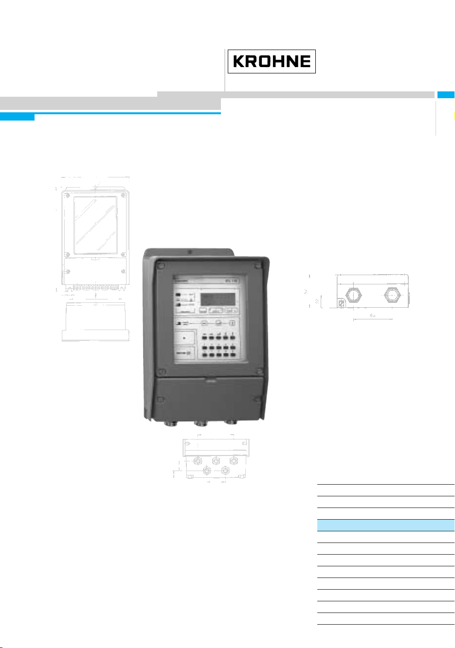
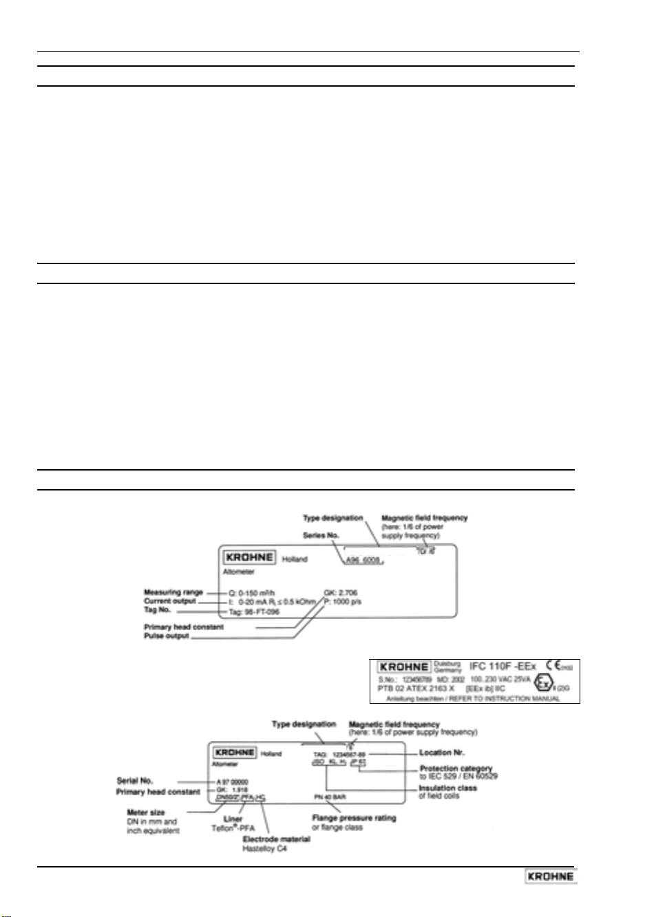
Instrument nameplates
Signal converter (example)
IFC 110 F
Signal converter IFC 110F-EEx (example)
Flow sensor (example)
LTOFLUX 4000 F
4 IFC 110 F
05/2003
Page 5
System description
Electromagnetic flowmeters are precision instruments designed for linear flow measurement of
liquid products
The process liquids must be electrically conductive:, ≥ 5 µS/cm
(for cold demineralized water ≥ 20 µS/cm).
The full-scale range Q
can be set as a function of the meter size: flow velocity of 0.3 - 12 m/s
100%
or 1 - 40 ft/s (s. Section 10.4.).
Product liability and warranty
The electromagnetic flowmeters are designed solely for measuring the volumetric flowrate of
electrically conductive, liquid process products.
These flowmeters are available for use in hazardous areas.
Special regulations apply in this case, which are given in the special EEx directions.
Responsibility as to suitability and intended use of these electromagnetic flowmeters rests
solelywith the operator.
Improper installation and operation of the flowmeters (systems) may lead to loss of warranty.
In addition, the “General conditions of sale” forming the basis of the purchase contract are
applicable.
If flowmeters need to be returned to KROHNE, please note the information given on the last-butone page of these Instructions. KROHNE regrets that it cannot repair or check your flowmeter(s)
unless accompanied by the completed form sheet.
CE / EMC / Standards / Approvals
The here described Electromagnetic flowmeters meet the NAMUR Directive NE21,
the protection requirements of Directive 89/336/EEC in conjunction with EN
61326-1 (1997) and A1 (1998), as well as Directives 73/23/EEC and 93/68/EEC
in conjunction with EN 61010-1, and bear the CE marking.
Software history
Display & control unit Amplifier (ADC) Inputs and outputs (I/O)
Software Status Software Status Software Status
3.19937.02.00
current
IMPORTANT!
In respect of EEx versions, pay regard to all directions marked with the symbol,
and also the information given in Sect. 6.1 and 13.
Only the EEx flow sensor may be installed in the hazardous area. The EEx
certified signal converter must be installed outside the hazardous area!
8.13393.02.00
current
3.16230.01.00
current
IFC 110 F 5
05/2003
Page 6

Sect. 1.1 Part A System installation and start-up
1 Electrical connection: power supply
1.1 Location and important installation notes ……………………. PLEASE NOTE !
• Electrical connection in accordance with VDE 0100 ”Regulations for the erection of power
installations with nominal voltages up to 1000 V” or equivalent national regulations.
• Do not cross or loop cables inside the terminal compartment.
• Use separate wiring (PG screwed cable entries) for power supply, field current lines, signal
lines, outputs and inputs.
• Hazardous areas are subject to special regulations, see Section 6.1 and special installation
instructions for hazardous-duty versions.
• Do not expose signal converter and switchgear cabinets with built-in converters to direct
sunlight. Install a sunshade if necessary.
• Signal converters installed in switchgear cabinets require adequate cooling (e.g. by fans
or heat exchangers).
• Do not expose signal converters to intense vibration.
• Keep the distance between the flow sensor and signal converter as small as possible, for
empty pipe detection (EPD) ≤ 20 m / ≤ 66 ft. Observe maximum lengths of signal and field
current lines (see Section 1.3.4).
• Use KROHNE signal line A (type DS, standard) or signal line B (type BTS, bootstrap,
optional), standard length 10 m (33 ft).
• Generally use bootstrap signal lines B (type BTS) for PROFIFLUX 5000 F and VARIFLUX
6000 F flow sensors sized at DN 2.5-15 and 1/10’’-1/2’’ and for contaminated liquids which
tend to form electrically insulating deposits.
• Always calibrate flow sensor and signal converter together. During installation particular care
should therefore be given to identical settings of flow sensor constant GK (see instrument
nameplate of flow sensor). In case GK constants are not identical, the signal converter must
be adjusted to the flow sensor GK (see Sections 4 and 8.5).
• Dimensions of signal converter see Section 10.3.
IMPORTANT!
For EEx versions, also pay regard to all directions included in Sect. 6.1 and 13.
Only the EEx flow sensor may be installed in the hazardous area. The EEx
certified signal converter must be installed outside the hazardous area!
6 IFC 110 F
05/2003
Page 7

Part A System installation and start-up Sect. 1.2
1.2 Power supply - connection
PLEASE NOTE !
• Type of enclosure
• Dimensioning:
moisture must always be kept closed. The selected clearances and creeping distances comply
with VDE 0110 and/or IEC 664 regulations for contamination grade 2. Supply circuits and
output circuits are designed to meet standards of overvoltage classes III and II, respectively.
• Fuse protection, disconnecting device: fuse protection for the feeding power circuit, and also a
disconnecting device (switch, circuit breaker) for isolating the signal converters must be
provided (see also Sect. 1.3.5 and 1.3.6).
100-230 V AC (tolerance range 85-255 V AC)
• Observe information on the instrument nameplate, power supply voltage and frequency.
• The protective conductor PE of the power supply must be connected to the separate
U-clamp terminal inside the terminal compartment of the signal converter.
• CAUTION: do not remove the internal connection (line) inside the terminal compartment of the
signal converter (yellow/green wire) between the U-clamp terminal and terminal 10 protective conductor (protection class I instrument).
• Connection diagrams I - IV for the power supply and for the electrical connection between
flow sensor and signal converter, see Sections 1.3.5 (Standard) and 1.3.6 (EEx).
24 V AC / DC (tolerance ranges: AC 20.4 - 26.4 V / DC 18 - 31.2 V)
• Observe information on the instrument nameplate, power supply voltage and frequency.
• For technical reasons concerning the measuring process, a functional grounding conductor
FE has to be connected to the separate U-clamp terminal inside the terminal compartment of
the signal converter.
• A facility providing a reliable electrical separation (PELV) has to be provided for connections
to functional extra-low voltages (24 V AC / DC) - (VDE 0100 / VDE 0106 and/or IEC 364 /
IEC 536 or equivalent national regulations).
• Connection diagrams I - IV for the power supply and for the electrical connection between
flow sensor and signal converter, see Sections 1.3.5 (Standard) and 1.3.6 (EEx).
Warning: Instrument must be properly grounded to avoid personnel shock hazard.
IP 65 to IEC 529 / EN 60529 equivalent to NEMA 4/4X.
the flowmeter housing protecting the electronic equipment against dust and
IMPORTANT!
For EEx versions, also pay regard to all directions included in Sect. 6.1 and 13.
Only the EEx flow sensor may be installed in the hazardous area. The EEx
certified signal converter must be installed outside the hazardous area!
IFC 110 F 7
05/2003
Page 8
Sect. 1.3.1 Part A System installation and start-up
1.3 Electrical connection of flow sensors
1.3.1 General remarks on signal lines A and B and field current line C
Proper operation of the equipment is ensured when KROHNE signal lines A and B are used with
foil screen and magnetic shield.
• Signal lines must be firmly installed.
• Shields are connected via stranded drain wires.
• Underwater or underground routing is possible.
• Insulating material flame-retardant to IEC 332.1 / VDE 0742.
• Low-halogen, unplasticized signal lines which remain flexible at low temperatures.
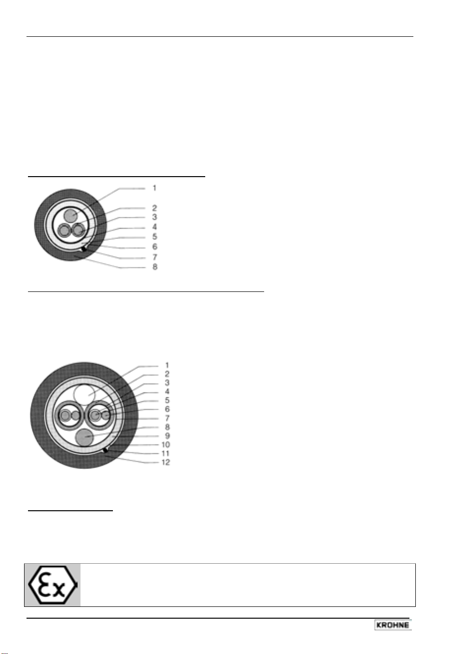
Signal line A (type DS) with double shielding
1 Stranded drain wire, 1st shield, 1.5 mm² or AWG 14
2 Insulation
3 Stranded wire 0.5 mm² or AWG 20 (3.1 red/3.2 white)
4 Special foil, 1st shield
5 Insulation
6 Mu-metal foil, 2nd shield
7 Stranded drain wire, 2nd shield, 0.5 mm² or AWG 20
Signal line B (type BTS) with triple shielding (bootstrap line)
8 Outer sheath
The bootstrap technology always controls the individual shields (3) of the signal converter exactly
to the voltage which is supplied to the signal conductors (5). As this prevents voltage differences
between the individual shields (3) and signal conductors (5), no current flows via the line
capacitances between 3 and 5. The line capacitance seems to become ”zero”.
This allows greater cable lengths in case the electric conductivity of the liquid to be measured is
low.
1
Dummy glider wire
2
Insulation (2.1 red/2.2 white)
3
Special foil, 1st shield (3.1/3.2)
4
Insulation (4.1/4.2)
5
Stranded wire 0.5 mm² or AWG 20
(5.1 red/5.2 white)
6
Stranded drain wire, 1st shield, 0.5 mm² or
AWG 20 (6.1/6.2)
7
Special foil, 2nd shield
8
Stranded drain wire, 2nd shield, 1.5 mm² or AWG 14
9
Insulation
10
Mu-metal foil, 3rd shield
11
Stranded drain wire, 3rd shield, 0.5 mm² or AWG 20
12
Outer sheath
Field current line C1
Line 2 x 0.75 mm² (18 AWG) Cu or 2 x (4 x) 1.5 mm² (14 AWG) Cu (Cu = copper cross section)
The cross section depends on the required cable length.
For max. permissible cable lengths please refer to Section 1.3.4
IMPORTANT!
For EEx versions, also pay regard to all directions included in Sect. 6.1 and 13.
Only the EEx flow sensor may be installed in the hazardous area. The EEx
certified signal converter must be installed outside the hazardous area!
8 IFC 110 F
05/2003
Page 9
Part A System installation and start-up Sect. 1.3.2
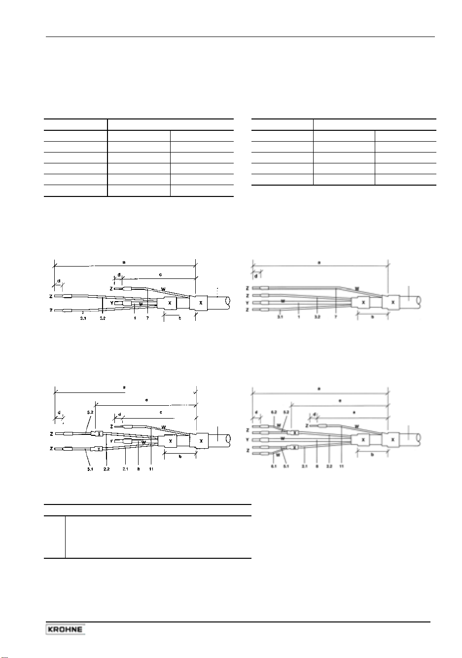
1.3.2 Stripping (preparation) of signal cables
Please note: The numbers in the drawings designate the stranded drain wires of signalling cables
A and B, see sectional drawings in Sect. 1.3.1.
Flow sensor Converter
Length flow sensor Length Converter
mm inch mm inch
a 90 3.60 a 50 2.00
b 8 0.30 b 8 0.40
c 25 1.00 d 8 0.40
d 8 0.30 e 20 0.80
e 70 2.80
Signal cable A (type DS),
double shielding
for flow sensor
Signal cable A (type DS),
double shielding
for IFC 110 F Converter
Signal cable A
bending radius
≥ 50 mm (≥ 2”)
Signal cable B (type BTS),
with triple shielding (bootstrap)
for flow sensor
Signal cable B
bending radius
≥ 50 mm (≥ 2”)
Customer-supplied materials
W
Insulation tubing (PVC), Ø 2.0-2.5 mm (Ø 1”)
X
Heat-shrinkable tubing or cable sleeve
Y
Wire end sleeve to DIN 41 228: E 1.5-8
Z
Wire end sleeve to DIN 41 228: E 0.5-8
Signal cable A
bending radius
≥ 50 mm (≥ 2”)
Signal cable B (type BTS),
with triple shielding (bootstrap)
for IFC 110 F Converter
Signal cable B
bending radius
≥ 50 mm (≥ 2”)
IFC 110 F 9
05/2003
Page 10
Sect. 1.3.3 Part A System installation and start-up
1.3.3 Grounding of flow sensor
• The flow sensor must be correctly connected to ground.
• The grounding cable may not transfer interference voltages.
• Do not use the grounding cable to connect more than one device to ground.
• In hazardous areas the grounding line is also used for potential equalizing purposes. Special
grounding instructions are contained in the installation instructions for hazardous-duty
instruments (only supplied together with such instruments).
• The flow sensor is connected to ground by means of a functional grounding conductor FE.
• Special grounding instructions for the connection of several flow sensors are contained in the
separate installation instructions of the flow sensors.
• These instructions also contain detailed descriptions on how to use grounding rings and how
to install flow sensors in metal or plastic pipes or in pipes which are coated on the inside.
Warning: Instrument must be properly grounded to avoid personnel shock hazard.
IMPORTANT!
For EEx versions, also pay regard to all directions included in Sect. 6.1 and 13.
Only the EEx flow sensor may be installed in the hazardous area. The EEx
certified signal converter must be installed outside the hazardous area!
10 IFC 110 F
05/2003
Page 11
Part A System installation and start-up Sect. 1.3.4
1.3.4 Cable lengths (max. distance between signal converter and flow sensor)
Abbreviations and explanations
The abbreviations used in the following tables, diagrams and connection diagrams stand for:
A Signal line A (type DS) with double shielding, max. length see diagram
B Signal line B (type BTS) with triple shielding, max. length see diagram
C Field current line, minimum cross section (A
) and max. length see table
F
D High-temperature silicone line, 3x1.5 mm² (14 AWG) Cu, with single shield,
max. length 5 m (16 ft)
E High-temperature silicone line, 2 x 1.5 mm² (14 AWG) Cu, max. length 5 m (16 ft)
Cross section of field current line C in Cu, see table
A
F
L Cable length in m or ft
Electrical conductivity of the process liquid
Κ
ZD Intermediate connection box required in connection with lines D and E for flow sensors
ALTOFLUX 4000 F, PROFIFLUX 5000 F and VARIFLUX 6000 F for process temperatures
exceeding 150°C (302°F).
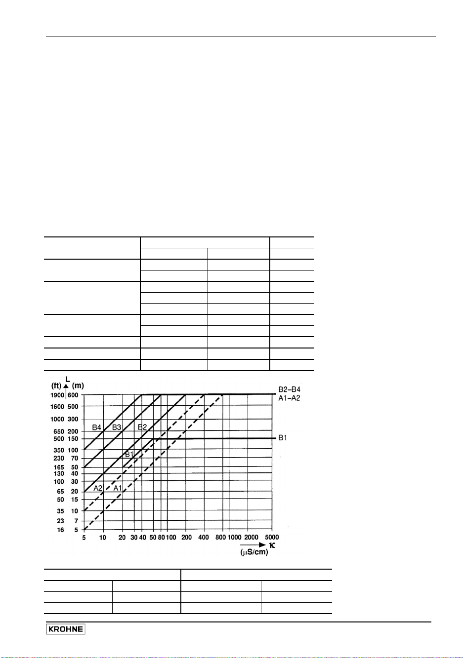
Recommended length of signal line
for magnetic field frequencies ≤ 1/6 x power frequency
Flow Meter size Signal Please note!
sensor DN mm Inch line
VARIFLUX 6000 F 2.5 - 15 1/10 - 1/2 B1
25 - 80 1 - 3 A1 / B3
PROFIFLUX 5000 F 2.5 - 1/10 - B1
4 - 15 1/6 - 1/2 B2
For application with
empty pipe detection
(EPD) max. length
< 20 m / 66 ft.
25 - 100 1 - 4 A1 / B3
ALTOFLUX 4000 F 10 - 150 3/8 - 6 A1 / B3
200 - 1200 8 - 48 A2 / B4
ALTOFLUX 2000 F 150 - 250 6 - 10 A2 / B4
ECOFLUX 1000 F 10 - 150 3/8 - 6 A1 / B3
M900 10 - 300 3/8 - 12 A2 / B4
Max. length and minimum cross section of field current line
Length L Cross section AF (Cu), minimum
0 to 150 m 5 to 500 ft 2 x 0.75 mm² Cu 2 x 18 AWG
150 to 300 m 500 to 1000 ft 2 x 1.50 mm² Cu 2 x 14 AWG
300 to 600 m 1000 to 1900 ft 4 x 1.50 mm² Cu 4 x 14 AWG
IFC 110 F 11
05/2003
Page 12
Sect. 1.3.5 Part A System installation and start-up
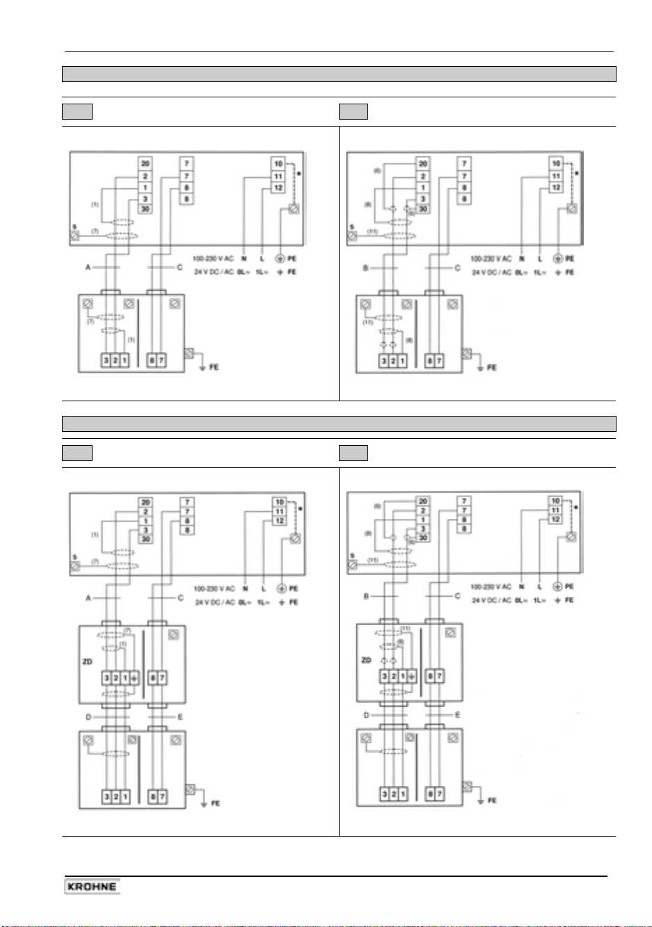
1.3.5 Connection diagrams for power supply and flow sensors
Important remarks for circuit diagrams PLEASE NOTE !
• The figures in brackets indicate the stranded drain wires of the shields (see cross-sectional
drawings of signal lines in Section 1.3.1).
• Electrical connection to VDE 0100 ”Regulations for the erection of power installations with
nominal voltages up to 1000 V”
• Power supply 24 V AC / DC:
• Systems to be used in hazardous areas are subject to special regulations applying to
electrical connections (see Section 1.3.6) for hazardous-duty instruments.
• PE = protective conductor
Do not remove the internal connection (cable) inside the terminal compartment of the signal
converter (yellow/green wire) between the U-clamp terminal and terminal 10 (protective
*
conductor for protection class I instruments).
IMPORTANT!
Electrical connection of EEx flow sensors and EEx signal converters to be carried
out as described in Sect. 1.3.6.
protective extra-low voltages (PELV) acc. to VDE 0100/
VDE 0106 and/or IEC 364/IEC 365, or corresponding
national regulations.
FE = functional ground conductor
12 IFC 110 F
05/2003
Page 13
Part A System installation and start-up Sect. 1.3.5
Process temperature below 150°C (302°F)
I Signal cable A (type DS) II Signal cable B (type BTS)
IFC 110 F V 2.0 IFC 110 F V 2.0
Flow sensor Flow sensor
III Signal cable A (type DS) IV Signal cable B (type BTS)
Process temperature above 150°C (302°F)
IFC 110 F V 2.0 IFC 110 F V 2.0
Flow sensor Flow sensor
IFC 110 F 13
05/2003
Page 14

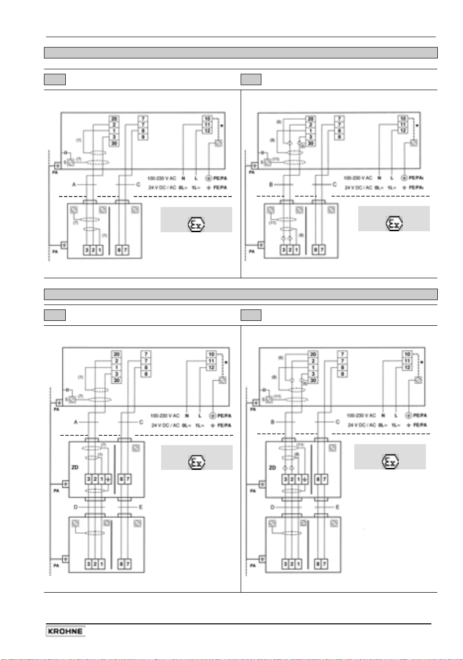
Sect. 1.3.6 Part A System installation and start-up
1.3.6 EEx-Connection diagrams for power supply and flow sensors
PLEASE NOTE!
• The figures in brackets indicate the stranded drain wires for the shields (see cross-sectional
drawing of signal cable in Section 1.3.1).
• The connections for the intrinsically safe electrode circuit including the shield terminals
are safety-separated up to a peak value of 375 V from the terminals for thepower supply,
for the inputs/outputs and for the field circuit. They are galvanically isolated from the housing
(PE/PA).
• For connection of the intrinsically safe electrode circuit including shield terminals to the
primary head, please refer to Item 12 in EN 60079-14.
The non-intrinsically safe field circuit to be connected to the primary head in keeping with the
requirements of Item 9 in EN 60079-14 .
• The non-intrinsically safe input and output circuits may only be routed into the hazardous
area in compliance with appropriate measures as specified in EN 60079-14.
• Supply power (terminals 11,12)
In conformity with current regulations for electrical installations, an isolating facility is required
to be provided for the signal converter. The housing of the IFC 110 F – EEx signal converter
must be incorporated in the equipotential bonding system (via external PA connection).
Note!
A PE safety conductor is not connected if a functional extra-low voltage with safety
separation (PELV) is used. Grounding is then carried out by way of the equipotential
bonding conductor.
• Electrode circuit (terminals 1, 20, 2, 3, 30 and shield terminal S)
In conformity with the requirements for separation of intrinsically safe circuits, Category ib to
EN 50 020, the cable for the intrinsically safe electrode circuit must, up to the terminals, be
separated from all non-intrinsically safe circuits.
Terminals 20 and 30 are optionally provided for connecting cables with single shielding. The
terminal for the outer shield (S) is capacitance grounded in the signal converter. The outer
overall shield to be connected by the shortest possible wire to the shield terminal. Shields to
be carefully insulated from ground and from each other.
• Field circuit FSV (terminals 7, 8)
The field circuit is all-pole protected on the FSV circuit board with an internal fusible link
160mA / 250V.
• Input/output circuits
The connection is made to functional extra-low voltage circuits with safety separation (PELV).
The I/O functions and technical data are described in the Standard Installation and Operating
Instructions.
IMPORTANT!
For EEx versions, also pay regard to all directions included in Sect. 6.1 and 13.
Only the EEx flow sensor may be installed in the hazardous area. The EEx
certified signal converter must be installed outside the hazardous area!
Do not remove the internal connection (cable) inside the terminal compartment of the signal
converter (yellow/green wire) between the U-clamp terminal and terminal 10 (protective
*
conductor for protection class I instruments).
14 IFC 110 F
05/2003
Page 15
Part A System installation and start-up Sect. 1.3.6
Process temperature below 150°C (302°F)
I Signal cable A (type DS) II Signal cable B (type BTS)
IFC 110 F V 2.0 IFC 110 F V 2.0
Hazardous area
Hazardous area
Flow sensor Flow sensor
III Signal cable A (type DS) IV Signal cable B (type BTS)
IFC 110 F V 2.0 IFC 110 F V 2.0
Process temperature above 150°C (302°F)
Hazardous area
Hazardous area
Flow sensor Flow sensor
IFC 110 F 15
05/2003
Page 16
Sect. 2.1 Part A System installation and start-up
2 Electrical connection: outputs and inputs
IMPORTANT!
For EEx versions, also pay regard to all directions included in Sect. 6.1 and 13.
Only the EEx flow sensor may be installed in the hazardous area. The EEx
certified signal converter must be installed outside the hazardous area!
2.1 Important information for outputs and inputs …….…………. PLEASE NOTE !
• The signal converter has the following outputs and inputs:
Output and Symbol Terminals Remarks
input group
Power output I IS / I active / passive selectable
Current output P P / P for electronic totalizers
Pulse output A1* (P2)
Status outputs A1* and A2
Status outputs D1 and D2
Control inputs C1 and C2
A1* / A⊥
A1* / A⊥ / A2 A⊥ common centre grounding contact
D1 / D⊥ / D2 D⊥ common centre grounding contact
C1 / C⊥ / C2 C⊥ common centre grounding contact
Internal power supply E E+ / E- for active mode of outputs and inputs
* Output A1 can be used as a 2nd pulse output P2 for electromechanical totalizers or as a
4th status output, see Section 4.4, Fct. 3.07 HARDWARE.
• The output and input groups are electrically isolated from each other and from all other input
and output circuits.
• Please note:
A⊥ common centre grounding contact for outputs A1 and A2
D⊥ common centre grounding contact for outputs D1 and D2
C⊥ common centre grounding contact for control inputs C1 and C2
• Active mode:
the signal converter supplies the power for the operation (selection) of
receiver instruments, observe max. operating data (terminals E+ and E-).
• Passive mode:
the operation (selection) of receiver instruments requires an external
power supply (U
), observe max. operating data.
ext
• Connection diagrams of outputs and inputs are shown in Section 2.6.
• For operating data of outputs and inputs please refer to Sections 2.6 and 10.1.
for electromechanical totalizers
16 IFC 110 F
05/2003
Page 17

Part A System installation and start-up Sect. 2.2
2.2 Current output I
• The current output is electrically isolated from all other circuits.
• Setting data and functions can note down in the Table in Sect. 3.
Please also refer to Section 2.7 ”Standard factory settings”.
• All operating data and functions are adjustable (see Sections 4.4 and 5.6, Fct. 1.05).
• Max. load :
• Selfcheck :
- short-circuit of mA loop via test function, see Fct. 2.03
or when power supply is switched on in Fct. 3.07
Error message on display (see Fct. 1.04, Section 5.4) and/or
status output (see Fct. 1.07-1.10, Section 5.8).
• Current value for error identification is adjustable, see Fct. 1.05 and Section 5.6.
• Range change-over, automatically or externally by control input,
see Sections 4.4 and 5.19, Fct. 1.07-1.10 and 1.11-12.
Setting range from 5-80% of Q
(corresponding low to high range ratio from 1:20 to 1:1.25).
Change-over from high to low range at approx. 85% of low range and vice versa at approx.
98% of low range.
The active range is signalled via one of the four status outputs.
• Forward/reverse flow measurement (F/R mode) is possible (see Section 5.15).
• Connection diagrams see Section 2.6.
active operation 15-500 Ω
passive operation
≤ 800 Ω
- interrupting the mA loop, and
100%
IFC 110 F 17
05/2003
Page 18
Sect. 2.3.1 Part A System installation and start-up
2.3 Pulse outputs P and A1
2.3.1 Pulse output P for electronic totalizers (EC)
• Pulse output P is electrically isolated from all other circuits.
• Setting data and functions can note down in the Table in Sect. 3.
Please also refer to Section 2.7 ”Standard factory settings”.
• All operating data and functions are adjustable, see Sections 4.4 and 5.7, Fct. 1.05.
• Active mode:
Passive mode:
• Max. adjustable frequency 10 kHz
• Scaling
in pulses per unit volume
• Pulse width
automatic
pulse duty factor approx. 1:1 at Q
pulse width range from 0.01 to 1 s
correspondingly lower output frequency.
• Forward/reverse flow measurement (F/R mode) is possible, see Section 5.15.
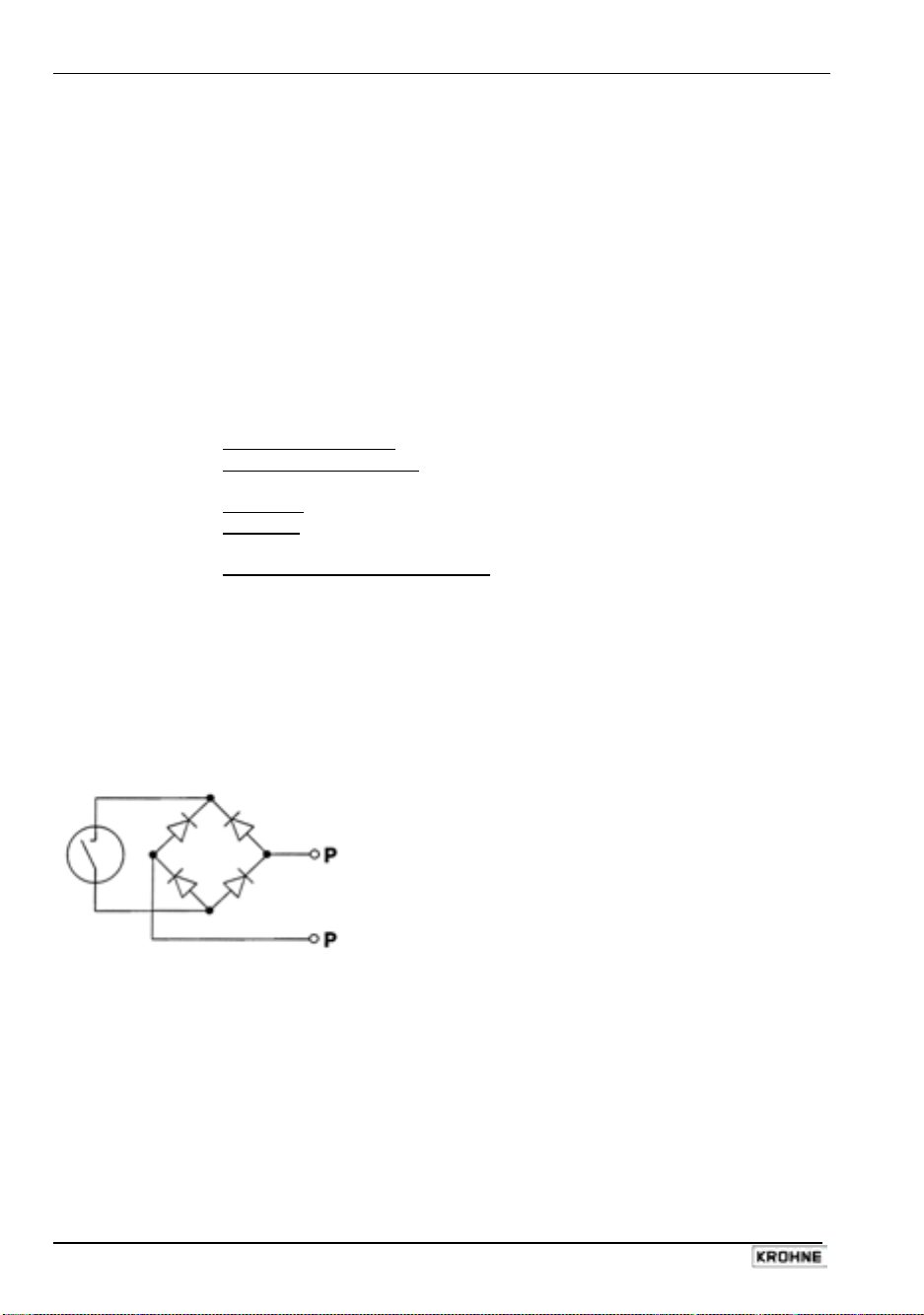
• Connection diagrams see Section 2.6
• Schematic wiring diagram for pulse output P for electronic totalizers EC
Similar to a relay contact, this pulse output switches direct and alternating voltages.
uses the internal power supply, terminals E+/Erequires external power supply, U
in pulses per unit time
(e.g. 1000 pulses/s at Q
≤ 32V DC/24V AC, I ≤ 30mA
ext
(e.g. 100 pulses/m³ or US Gal).
symmetric
, pulse duty factor 1:1, independent of output frequency,
, with optimum pulse width,
, or
100%
adjustable as required for
100%
flow) or
18 IFC 110 F
05/2003
Page 19

Part A System installation and start-up Sect. 2.3.2
2.3.2 Pulse output A1 for electromechanical totalizers (EMC)
PLEASE NOTE:
The output terminal A1 can be used as status output A1 or as a 2nd pulse output A1 for
electromechanical totalizers.
Setting is as described in Fct. 3.07 HARDWARE, see Sections 4.4 and 5.18.
• Pulse output A1 is electrically connected to status output A2 (common centre grounding
contact A⊥) but electrically isolated from all other circuits.
• Setting data and functions can note down in the Table in Sect. 3.
Please also refer to Section 2.7 ”Standard factory settings”.
• All operating data and functions are adjustable, see Sections 4.4 and 5.7, Fct. 1.07.
• Active mode:
• Passive mode:
uses the internal power supply, terminals E+/Erequires external power supply, U
≤ 32V DC/24V AC, I ≤ 100mA
ext
(I ≤ 200mA for polarized DC operation, see Section 6.3)
• Max. adjustable frequency 50 kHz
• Scaling
in pulses per unit of time
(e.g. 10 pulses/s at Q
100%
flow) or
in pulses per unit of volume (e.g. 10 pulses/m³ or US Gal).
• Pulse width
symmetric
, pulse duty factor 1:1, independent of output frequency,
automatic, with optimum pulse width,
pulse duty factor approx. 1:1 at Q
pulse width range from 0.01 to 1 s
, or
100%
adjustable as required for
correspondingly lower output frequency.
• Forward/reverse flow measurement (F/R mode) is possible, see Section 5.15.
• Connection diagrams see Section 2.6
• Schematic wiring diagram for pulse output A1 for electromechanical totalizers EMC.
This pulse output has a MOSFET switch as output which switches direct and alternating
voltages similar to a relay contact.
IFC 110 F 19
05/2003
Page 20

Sect. 2.4 Part A System installation and start-up
2.4 Status outputs A1 / A2 / D1 / D2
PLEASE NOTE:
The output terminal A1 can be used as status output A1 or as a 2nd pulse output A1 for
electromechanical totalizers.
Setting is as described in Fct. 3.07 HARDWARE, see Sections 4.4 and 5.18.
• Status outputs A1/A2 and D1/D2 with the common centre grounding contacts A⊥ and B⊥ are
electrically isolated from each other and from all other circuits.
• Setting data and functions can note down in the Table in Sect. 3.
Please also refer to Section 2.7 ”Standard factory settings”.
• All operating data and functions are adjustable, see Sections 4.4 and 5.8, Fct. 1.07-1.10.
• Active mode:
Passive mode:
uses the internal power supply, terminals E+/Erequires external power supply, U
≤ 32V DC/24V AC, I ≤ 100mA
ext
(I ≤ 200mA for A1 in case of polarized DC operation, see Section 6.3)
• The following operating conditions can be signalled using the status outputs:
- flow direction (F/R mode)
- limits
- error messages
- active range in case of range change-over
- inverse operation of A1 and A2 or D1 and D2,
i.e. used as change-over switch with common centre grounding contact A⊥ or D⊥.
• Connection diagrams see Section 2.6
• Schematic wiring diagram for status outputs A1/A2 and D1/D2.
This status outputs have MOSFET switches as outputs which switch direct and alternating
voltages similar to relay contacts.
2.5 Control inputs C1 and C2
• Control inputs C1 and C2 are electrically connected (common centre grounding
contact C⊥) but electrically isolated from all other circuits.
• Setting data and functions can note down in the Table in Sect. 3.
Please also refer to Section 2.7 ”Standard factory settings”.
• All operating data and functions are adjustable, see Sections 4.4 and 5.9, Fct. 1.11-1.12.
• Active mode:
Passive mode:
uses the internal power supply, terminals E+/Erequires external power supply, U
≤ 32V DC/24V AC, I ≤ 10mA
ext
• The following operating conditions can be initiated using the control inputs:
- external range change
- holding of output values
- zeroing the outputs
- resetting the internal totalizer
- resetting (deleting) the error messages
• Connection diagrams see Section 2.6
20 IFC 110 F
05/2003
Page 21
Part A System installation and start-up Sect. 2.6
2.6 Connection diagrams of outputs and inputs
IMPORTANT!
For EEx versions, also pay regard to all directions included in Sect. 6.1 and 13.
Only the EEx flow sensor may be installed in the hazardous area. The EEx
certified signal converter must be installed outside the hazardous area!
I
P, A1*
A1*, A2,
D1, D2
C1, C2
Current output (included HART
Pulse output
Status outputs
Control inputs
Totalizer
-electromechanical (EMC)
- electronic (EC)
milliampmeter
0-20 mA or 4-20 mA and other
Key, N/O contact
External voltage source (U
connection polarity arbitrary
DC voltage,
external power source (U
Active mode: the IFC 110 F supplies the power required for operating (driving) the receiver
instruments. Observe the max. operating data (terminals E+ and E-).
Passive mode: an external power supply source (Uext) is required for operating (driving) the
receiver instruments.
Groups A / C / D / E / I / P are electrically isolated from each other and from all other input and
output circuits.
Please note:
common reference potential
A⊥ for A1 and A2
C⊥ for C1 and C2
D⊥ for D1 and D2
®
)
), DC or AC voltage,
ext
), note connection polarity
ext
Please note ! Unwired
contacts or terminals may not
have any conductive
connection with other
electrically conducting parts.
Interface operation with
HART® or RS 485 (Option)
see Sect. 6.4.
*
selectable as
status output A1 or
pulse output A1
IFC 110 F 21
05/2003
Page 22
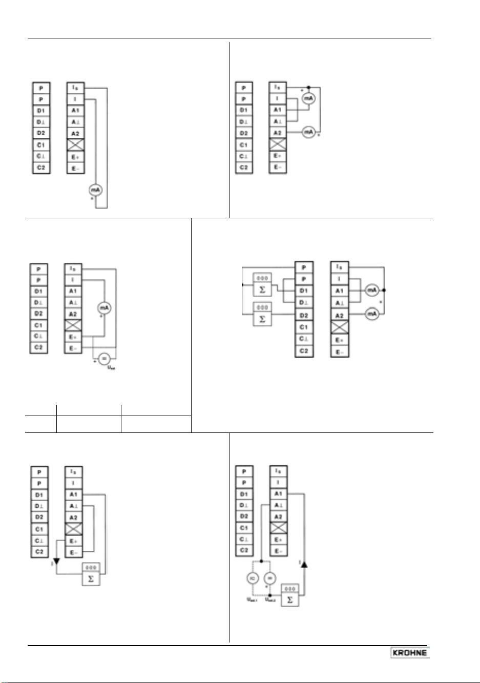
Sect. 2.6 Part A System installation and start-up
Current output I
{
active
Current output I
|
range change BA
with automatic
active
without external change-over relay
low range
high range
Ri 15 - 500 Ω
Ri 15 - 500 Ω
Current output I
}
(see Sect. 6.8 passive/active for pulse and current outputs (P and I
passive
Forward/reverse flow meausrement (F/R mode)
~
active
)
operation without external change-over relay
reverse
flow
forward
flow
reverse
flow
forward
flow
Ri 15 - 500 Ω
selectable with internal power supply
E or external power supply U
the connection diagrams for pulse output P on the
ext.
Electronic totalizers must be connected as shown in
following page.
U
15 - 22 V DC 22 - 32 V DC
ext.
R
0 - 500 Ω 0 - 800 Ω
i
Pulse output A1 active
Pulse output A1 passive
for electromechanical totalizers (EMC) for electromechanical totalizers (EMC)
≤ 32 V DC / ≤ 24 V AC I ≤ 10 mA
Ri ≥ 160 Ω
I ≤ 100 mA
22 IFC 110 F
U
ext.
oder umschaltbar auf
≤ 32 V DC I ≤ 200 mA
U
ext.2
05/2003
Page 23
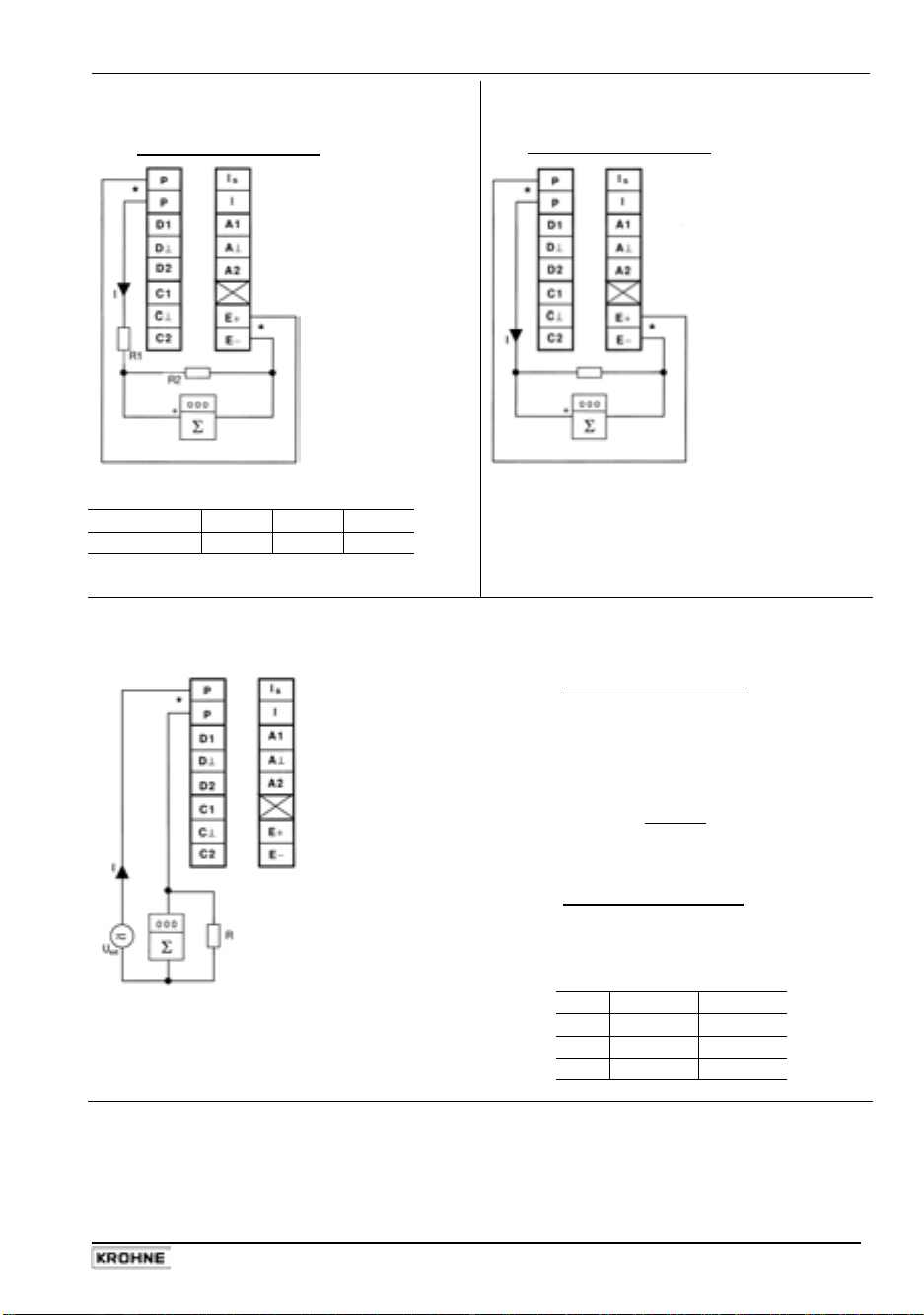
Part A System installation and start-up Sect. 2.6
Pulse output P
active
for electronic totalizers (EC)
for frequencies ≤ 1 kHz
Pulse output P
for electronic totalizers (EC)
for frequencies > 1 kHz
active
R1 = 1 kΩ/0.5 W I ≤ 20 mA R
> 100 kΩ R = 1 kΩ/0.35 W I ≤ 30 mA
i EC
R2 / 0.2 W
U
EC max
10 kΩ 1 kΩ 270 Ω
22 V 12 V 5 V
Pulse output P
passive
for electronic totalizers (EC)
for frequencies ≤ 1 kHz
U
≤ ≤ 32 V DC / ≤ 24 V AC
ext
I
≤ ≤ 30 mA
R
=
1 - 10 kΩ
P
≥
R
2
U
ext
R
for frequences > 1 kHz
U
=
ext
R
i EC
I ~ 30 mA ~ 18 mA
R
P
R
U
EC
≤ 24 V DC / AC
≥ 100 kΩ
560 Ω 1 kΩ
0.5 W 0.35 W
16 V 18 V
* Shielded cables
must be used to prevent radio interference at pulse output frequencies > 100 Hz
IFC 110 F 23
05/2003
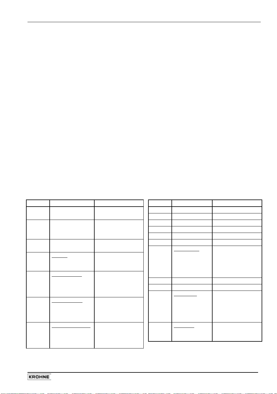
Page 24

Sect. 2.6 Part A System installation and start-up
Status outputs D1 / D2 / A1 / A2 active
I ≤ 100 mA
e.g. message display
9
Control inputs C1 / C2 active
Status outputs D1 / D2 / A1 / A2 passive
≤ 32 V DC / ≤ 24 V AC
U
ext.
I ≤ 100 mA
9
e.g. message display
Control inputs C1 / C2 passive
Contacts 24 V, 10 mA
I ≤ 7 mA I ≤ 10 mA
24 IFC 110 F
≤ 32 V DC / ≤ 24 V AC
U
ext.
05/2003
Page 25
Part A System installation and start-up Sect. 2.7
2.7 Standard factory settings
• All operating data are set at the factory in accordance with the specifications contained in the
order.
• If no specifications are made in the order, instruments will be delivered with the standard
parameters and functions indicated in the table below.
• To facilitate the start-up of the instrument, current and pulse outputs are set to handle
measurements in ”two flow directions” so that the current flow rates and volumes are displayed
and/or counted independent of the direction of flow. The figures displayed may have a
preceding sign.
• Such factory setting of current and pulse outputs may lead to measuring errors, particularly
when volumes are metered and totalized.
• If e.g. pumps are switched off and ”backflows” occur which are not within the low-flow cutoff
(SMU) range, or if separate displays and counts are required for both flow directions.
• To avoid faulty measurements, it may therefore be necessary to change the setting of the
following functions:
- SMU low-flow cutoff Fct. 1.03, Section 5.3
- display Fct. 1.04, Section 5.5
- current output I Fct. 1.05, Section 5.6
- pulse output P Fct. 1.06, Section 5.7
• For special applications, such as pulsating flows, see Sections 6.5 to 6.10
Standard factory settings
Fct. No. Function Setting Fct. No. Function Setting
1.01 Full-scale range See instr. nameplate 1.08 Status output A2 ON
of flow sensor 1.09 Status output D1 All error
1.02 Time constant 3 Sec. for display, 1.10 Status output D2 Indication F/R
pulse, current and 1.11 Control input C1 Totalizer reset
status ouputs 1.12 Control input C2 OFF
1.03 Low-flow cutoff ON: 1% 3.01 Language German
OFF: 2% 3.02 Flow sensor
1.04 Display meter size See instr. nameplate
flow rate m³/h direction of flow + direction,
totalizer m³ see arrow on
1.05 Current output I
function 2 directions 3.04 Entry code NO
range 4-20 mA 3.05 User unit Liter/h
error detection 22 mA 3.06 Application
1.06 Pulse output P flow steady
function 2 directions empty pipe NO
pulse value 1000 pulses/Sec. ADC gain automatic
pulse width symmetric special filter OFF
1.07 Pulse output 2, A1 3.07 Hardware
function 2 directions terminal A1 pulse output A1
pulse value 1 pulse/s selfcheck NO
pulse width 50 ms
flow sensor
active
IFC 110 F 25
05/2003
Page 26
Sect. 3 Part A System installation and start-up
3 Start-up
• Before connecting to power, check that the instrument is correctly installed as described in
Sections 1 and 2.
• The flowmeter, flow sensor and signal converter are delivered ready for operation. All
operating data are set at the factory in accordance with your specifications.
Please also refer to Section 2.7 ”Standard factory settings”.
• Switch on the power supply. The flowmeter immediately begins to measure the flow.
• When the power supply is switched on, the display successively shows START UP and
READY. Then the current flow rate and/or the current totalizer count are displayed. Displays
are either steady or cyclic depending on the setting described for Fct. 1.04.
• 2 light-emitting diodes (LED) in the ”diagnostics” field on the front panel of the signal
converter indicate the status of measurement.
LED displays Status of measurement
Green ”normal” LED Everything O.K.
is flashing
Green ”normal” LED Momentary overload of outputs and/or A/D converter.
and red ”error” LED Detailed error messages by setting Fct. 1.04 DISPLAY,
are flashing alternately subfunction ”MESSAGES” to ”YES”, see Sections 4.4 and 5.5.
Red ”error” LED is Fatal Error, see Sections 7.3 and 7.4
flashing
IMPORTANT!
For EEx versions, also pay regard to all directions included in Sect. 6.1 and 13.
Only the EEx flow sensor may be installed in the hazardous area. The EEx
certified signal converter must be installed outside the hazardous area!
26 IFC 110 F
05/2003
Page 27
Part B IFC 110 F Signal converter Sect. 3
Setting data: Here you can note down the settings of the signal converter !
Fct. No. Function Settings
1.01 Full-scale range
1.02 Time constant
1.03 Low-flow cut-off
1.04 Display
1.05 Current output I
1.06 Pulse output P
1.07 Pulse output A1 or
Status output A1
(for setting see below, Fct. 3.07,
terminal A1)
1.08 Status output A2
1.09 Status output A3
1.10 Status output A4
1.11 Control input C1
1.12 Control input C2
3.01 Language
3.02 Flow sensor
3.04 Entry code required ?
3.05 User-defined unit
3.06 Application
3.07 Hardware-settings Terminal A1 is
or
3.08 Measuring point
3.09 Communication
ON: OFF:
Flow
Totalizer
Messages
Trend
Function
Reverse range
Range I
Error
Function
Pulswidth
Pulse value
Meter size
GK value
Field frequency
Power frequency
Flow direction
no yes
→ → → ↵ ↵ ↵ ↑ ↑ ↑
Flow is steady
pulsating
Empty Pipe no
Detection (EPD) yes
Pulse output
Status output
of
HART or
KROHNE RS 485
Address:
Baud rate:
IFC 110 F 27
05/2003
Page 28
Sect. 4.1 Part B IFC 110 F Signal converter
4 Operating of the signal converter
4.1 KROHNE operating concept
28 IFC 110 F
05/2003
Page 29
Part B IFC 110 F Signal converter Sect. 4.2
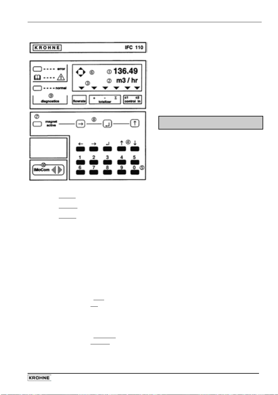
4.2 Operating and control elements
The instrument can be operated
by means of ....
…
the 15 keys ~
after removal of the glass cover,
…
the 3 magnetic sensors
bar magnet without opening the
housing (optional).
Display, 1st line Displaying numerical data
{
Display, 2nd line Displaying units and texts
|
Display, 3rd line 6 arrows to mark the current display
}
flow rate current flow rate
+
totalizer
-
control in
~
5 keys for operating the signal converter ← → ↵ ↑ ↓
10 keys for direct numerical setting of function values (not function numbers)
Compass field showing that a key is pressed
magnet active
green
red
3 magnetic sensors (optional), operated by bar magnet without opening the housing,
function of the sensors as described for the three keys → ↵ ↑, see
diagnostics
normal
error
IMoCom
supplementary equipment, see Section 6.4, slide window to the left
totalizer
totalizer
sum totalizer (+ and -)
Σ
1/2
control input 1 or 2 active
LED green/red, magnetic sensors active
= built-in magnetic sensors (optional), see
= operation of one of the 3 magnetic sensors
2 LEDs signalling the status of measurement
green LED
red LED
IMoCom bus, multipoint connector for connecting external
= correct measurement, everything O.K.
= error, parameter or hardware error
and accessible
.
~
and the
IFC 110 F 29
05/2003
Page 30
Sect. 4.3 Part B IFC 110 F Signal converter
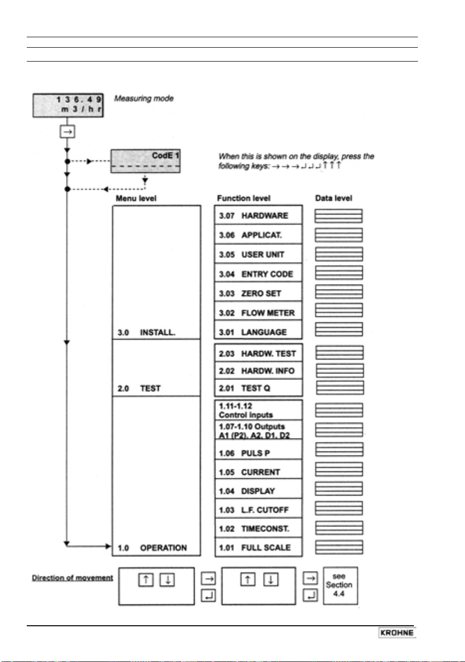
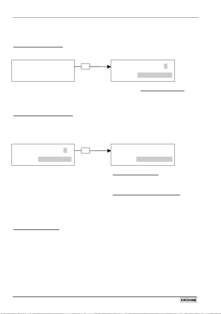
4.3 Key functions
In the following, the cursor or flashing part of the display is shown against a grey background.
To start operator control
Measuring mode
1 3 . 5 7 1
m 3 / h
PLEASE NOTE: if ”YES” is selected in Fct. 3.04 ENTRY CODE, ”CodE 1 - - - - - - - - -”
appears in the display after pressing the → key.
Enter the password for the entry code which is a sequence of 9 keys: → → → ↵ ↵ ↵ ↑ ↑ ↑
(each keystroke confirmed by ” * ”).
To terminate operator control
Press key ↵ any number of times until one of the following menus
Fct. 1.0 OPERATION, Fct. 2.0 TEST or Fct. 3.0 INSTALL is displayed.
F c t . 3. 0
I N S T A L L.
Store new parameters: acknowledge by
New parameters not to be stored:
Keyboard with 10 keys
The keyboard with the 10 keys (0-9) is used for setting all flashing numbers (cursor).
Exception: the digits of the function numbers, such as Fct. 1.03, can only be changed with
keys ↑ or ↓.
→
Press key ↵
↵
Operator control mode
F c t . 1. 0
O P E R A T I O N
S T O R E Y E S
pressing key ↵. Measuring mode is
continued with new parameters.
press key ↑ to display
”STORE NO”.
Measuring mode is continued with the ”old”
parameters after pressing key ↵.
30 IFC 110 F
05/2003
Page 31
Part B IFC 110 F Signal converter Sect. 4.3
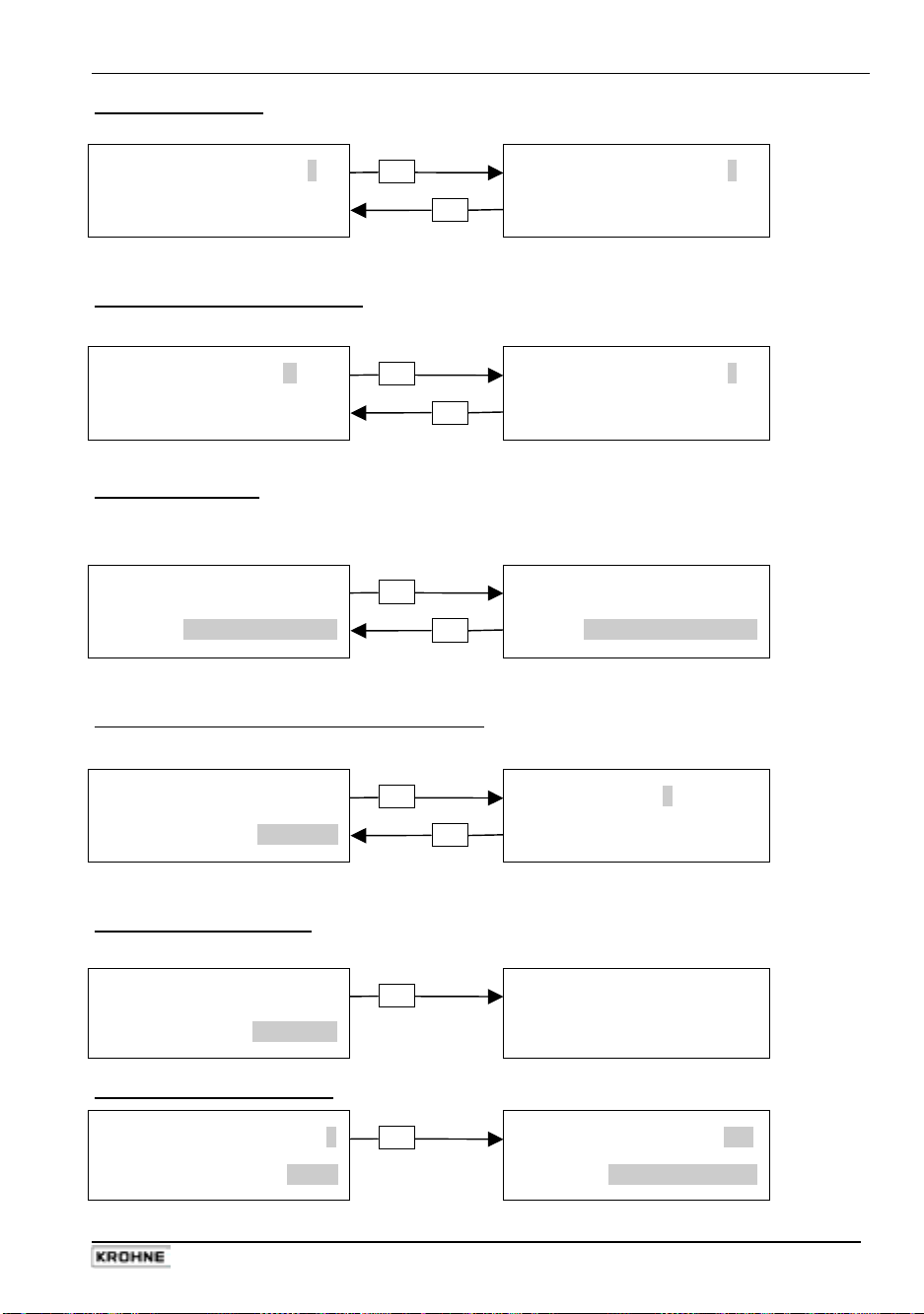
To change numbers
3 9 7. 3 5
m 3 / h
increase number
decrease number
3 9 7. 4 5
↑
m 3 / h
↓
To shift cursor (flashing position)
3 9 7. 3 5
m 3 / h
shift to right
→
shift to left
3 9 7. 3 5
m 3 / h
←
To alter texts (units)
In case of units, the numerical
value is converted automatically.
3. 7 6 9 9
L i t e r / S e c
select next text
select preceding text
9 3. 3 6 5
↑
U S. G a l / m i n
↓
To change from text (unit) to numerical setting
1 3. 5 7 1
m 3 / h
change to numerical setting
1 3. 5 7 1
→
return to text setting
m 3 / h
←
To change to subfunction
Subfunctions have no “Fct. No.” and are identified by a “→”
2 D I R.
↵
→
R A N G E I
To revert to function display
10. 3
S e c
F c t. 1. 0 2
↵
T I M E C O N S T.
IFC 110 F 31
05/2003
Page 32

Sect. 4.4 Part B IFC 110 F Signal converter
4.4 Table of settable functions
Abbreviations used:
A1, A2
Status outputs
(A1 can also be 2nd pulse output A1)
C1, C2
Control inputs
D1, D2
Status outputs
DN
Meter size, nominal size
F
= ½ x pulse width (s) for ≤ 50 Hz
max
≤ 10 kHz if ”AUTO” or ”SYM.” are selected in
subfunction ”PULSWIDTH”
F
= 10 pulses/h
min
FM
Conversion factor volume
see Fct. 3.05 ”FACT. VOL.”
F
Conversion factor time
T
see Fct. 3.05 ”FACT. TIME”
GK
Flow sensor constant
I
Current output
I
Current at 0% flow rate
0%
I
Current at 100% flow rate
100%
Fct. Text Description and setting
1.0 OPERATION Operating menu
FULL SCALE Full-scale range for flow rate Q
Selection of unit
Setting ranges
The range depends on the nominal width (DN) and the
flow velocity (v): Q
Nominal width/meter size v
● DN 2.5–1200 / 1/10”–48”: 0.0053 – 48 860 m³/h
0.0237 – 218 560 US.Gal/min
● DN 1300–3000 / 52”–120” 1435 – 305 360 m³/h
(see Section 8.6) 6415 – 1 366 000 US.Gal/min
been exceeded or would not have been reached.
1.02 TIMECONST. Time constant
Selection: ● ALL (applies to display and all outputs)
● ONLY I (only display, current and status outputs)
Range: ● 0.2 – 99.9 Sec
1.03 L.F. CUTOFF Low-flow cutoff (L.F. CUTOFF)
● OFF (fixed tripping points: ON = 0.1% / OFF = 0.2%)
● PERCENT (variable tripping points) ON OFF
1 – 19% 2 – 20%
Note: the cutoff ”OFF” value must be greater than the cutoff ”ON” value.
VALUE P
→
and/or
VALUE P2
→
P (P2)
Pulse output (2nd pulse output A1)
P
= F
max
P
min
Q
Q
100%
Q
max
for any unit,
for any unit,
Q
min
SMU
v
v
max
v
min
F/R
m³/h
•
user unit, factory setting ”Liter/h” or ”US MGal/day” (see Fct. 3.05)
•
•
max/Q100%
= F
min/Q100%
Current flow rate
100% flow rate = full-scale range
π
= /4 DN² x v
4
Q
100%
π
= /4 DN² x v
4
Q
100%
Low-flow cutoff for I and P
Flow velocity
Maximum flow velocity (12 m/s or 40 ft/s) at Q
Minimum flow velocity (0.3 m/s or 1 ft/s) at Q
Forward/reverse flow in F/R measuring mode
100%
Liter/Sec
Press → key to change to numerical setting
π
= DN² x v
min
4
= 0.3 m/s (1 ft/s) v
min
Press ↵ key to return to Fct. 1.01 FULL SCALE
Pulse value for pulse output P (Fct. 1.06 ”VALUE P”) and/or
for the 2nd pulse output A1 (Fct. 1.07 ”VALUE P2”) has been changed.
With the ”old” pulse values the output frequency (F) would have
/ Q
P
= F
min
min
100%
P
max
= F
max
/ Q
100%
Press ↵ key to change to numerical setting.
Press ↵ key to return to Fct. 1.02 TIMECONST.
Press → key to change to numerical setting.
Press ↵ key to return to Fct. 1.03 L.F. CUTOFF.
(= max. full-scale range
max
at v
= 12 m/s or 40 ft/s)
max
(= min. full-scale range
min
at v
= 0.3 m/s or 1 ft/s)
min
US.Gal/min
•
Q
min
= DN² x v
max
= 12 m/s (40 ft/s)
max
Check new values!
π
4
max
100%
100%
32 IFC 110 F
05/2003
Page 33

Part B IFC 110 F Signal converter Sect. 4.4
Fct. Text Description and setting
1.04 DISPLAY Display functions
→ DISP.FLOW
● NO DISP. ● User unit, factory setting ”Liter/h” or ”US MGal/day” (s. Sect. 3.05)
● m³/h ● PERCENT
● Liter/Sec ● BARGRAPH (value and bar graph display in %)
● US.Gal/min
● NO DISP. (totalizer is ON but no display)
● OFF (totalizer is OFF)
● + TOTAL. ● - TOTAL. ● +/- TOTAL.
● ALL (display single counts or all)
● m³ ● Liter ● US.Gal
● User unit, factory setting ”Liter” (s. Sect. 3.05)
Format setting
● Auto (exponent notation)
● # . ####### ● ##### . ###
● ## . ###### ● ###### . ##
● ### . ##### ● ####### . #
● #### . #### ● ########
● NO ● YES (cyclic change with display of measured values)
1.05 CURRENT I Current output I
● OFF (switched off)
● + DIR. ● - DIR. (measurement in one flow direction only)
● 2 DIR. (forward/reverse flow, F/R mode)
press this key to change to subfunction ”REV. RANGE”.
(only displayed when ”2 DIR.” is selected)
● 100 PCT. (same as forward flow Q
● PERCENT setting range: 005 - 150 % of Q
(different value for reverse flow)
● 0 - 20 mA ● 4 - 20 mA (fixed ranges)
● mA (user-defined range) I0% - I
(Value I0% < I
● 22 mA
1.06 PULS P Pulse output P
Description of function of pulse output P on the next page.
1.07 STATUS A1 Status output A1 A1 = terminal
PULS2 A1 2nd pulse output A1
Description of function of status output A1 or 2nd pulse output A1
DISP.TOTAL.
→
DISP.MSG.
→
FUNCT. I
→
REV.RANGE
→
RANGE I
→
I ERROR
→
or
Selection of flow display
Press ↵ key to change to subfunction ”DISP. TOTAL.”
Selection of totalizer display
● SUM (Σ)
Press ↵ key to change to setting of display unit.
Press → key to transfer to format setting.
Press ↵ key to change to subfunction ”DISP. MSG.”
Additional messages desired during measuring mode?
Press ↵ key to return to Fct. 1.04 DISPLAY.
Selecting the current output I function
Press ↵ key to change to subfunction ”RANGE I”; if ”2 DIR.” is selected
Setting the full-scale range for reverse flow of Q
, see Sect. 1.01)
100%
100%
Press → key to change to numerical setting.
Press ↵ key to change to subfunction ”RANGE I”
Selecting the measuring range
!) 0 - 16 mA 4 - 20 mA
Press → key to change to numerical setting!
Press ↵ key to change to subfunction ”I ERROR”.
Selecting the error value
Press → key to change to numerical setting.
Press ↵ key to return to Fct. 1.05 ”CURRENT OUTPUT I”.
connected as status or pulse output (P2)
on the next page.
100%
● 0.0 to I
}
mA (variable when I0% ≥ 1 mA, see above)
0%
s. Fct. 3.07 HARDWARE, ”Terminal A1”
100%
100%
IFC 110 F 33
05/2003
Page 34

Sect. 4.4 Part B IFC 110 F Signal converter
Fct. Text Description and setting
1.08 STATUS A2 Status outputs A2, D1 and D2
1.09 STATUS D1 Description of function of status outputs A2, D1 and D2
1.10 STATUS D2
1.11 CONTROL C1 Countrol inputs C1 and C2
1.12 CONTROL C2
1.06 PULS P Pulse output P for electronic totalizers up to 10,000 pulses/s
1.07 PULS2 A1 2nd pulse output A1 for electromechanical totalizers up to max. 50 Hz.
Connection of terminal A1 as a 2nd pulse output A1 or as status output A1,
FUNCT. P
→
FUNCT. P2
→
● + DIR. ● - DIR. (measuring in one flow direction only)
● 2 DIR. (forward/reverse flow, F/R mode)
SELECT P
→
SELECT P2
→
● PULSE/TIME (pulses per unit time for 100% flow rate)
PULSWIDTH
→
PULSWIDTH
→
● AUTO (automatic = 50% of cycle duration of 100% output frequency)
● SYM (symmetric = pulse duty factor approx. 1:1 across the entire range)
VALUE P
→
VALUE P2
→
● xxxx PulS/m³ ● xxxx PulS/Liter ● xxxx PulS/US.Gal
● xxxx PulS/user unit, factory setting ”Liter” or ”US MGal” (s. Fct. 3.05)
Setting range ”xxxx” depends on pulse width and full-scale range:
P
accordance with the same setting mode.
VALUE P
→
VALUE P2
→
● xxxx PulSe/Sec (=Hz) ● xxxx PulSe/min ● xxxx PulSe/h
Fct. 1.06 and 1.07 have identical menus and are configured in
● xxxx PulSe/user unit, factory setting ”h” (s. Fct. 3.05)
Setting range ”xxxx” depends on pulse width (see above).
}
on the next page but one.
}
Description of function of control inputs on the next page but one.
see Fct. 3.07 HARDWARE, ”Terminal A1”.
Selecting the function for pulse outputs P and P2
● OFF
Press ↵ key to change to subfunction ”SELECT P or P2”.
Selecting the type of pulse
● PULSE/VOL. (pulses per unit volume, flow rate)
Press ↵ key to change to subfunction ”PULSWIDTH”.
Selecting the pulse width
● 0.01 - 1.00 s (only for F
Press ↵ key to change to subfunction ”VALUE P or P2”.
Setting the pulse value per unit volume (only displayed when
”PULSE/VOL.” is selected in ”SELECT P or P2”
= F
/ Q
100%
, P
min
min
Press ↵ key to return to Fct. 1.06 PULS P or Fct. 1.07 PULS2 A1.
Setting the pulse value per unit time (only displayed when
”PULSE/TIME” is selected in ”SELECT P or P2”
Press ↵ key to return to Fct. 1.06 PULS P or Fct. 1.07 PULS2 A1.
< 50 pulses/s)
max
= F
max
max
/ Q
100%
above).
above).
34 IFC 110 F
05/2003
Page 35

Part B IFC 110 F Signal converter Sect. 4.4
Fct. Text Description and setting
1.07 STATUS A1 Status output A1 (terminal A1 connected as status output A1 or
1.08 STATUS A2 Status output A2
1.09 STATUS D1 Status output D1
1.10 STATUS D2 Status output D2
● INVERS D1 (inverse mode of D1 and D2)
● INVERS A1 (inverse mode of A1 and A2 possible only if A1
is operated as status output, see Fct. 3.07 HARDWARE, ”terminal A1”)
● SIGN I, P or P2
(F/R mode)
● OVERFL. I, P or P2
(overloading the outputs)
● EMPTY PIPE (”tube empty” signal only with built-in option)
● TRIP. POINT
Selection: ● + DIR. ● - DIR. ● 2 DIR.
Setting range: 000 - 150 PERCENT
● AUTO. RNG. Setting range: 05-80 PERCENT (= lower to upper range ratio
1:20 to 1:1.25, value must be higher than that of Fct. 1.03 L.F. CUTOFF)
Fct. Text Description and setting
1.11 CONTROL C1 Control input C1 and C2
1.12 CONTROL C2 ● OFF ● EXT. RNG. (external range change)
● OUTP. HOLD (hold output values)
● OUTP. ZERO (set outputs to ”min. values”)
● TOTAL.RESET (reset the totalizer)
● ERROR.RESET (delete error messages)
Fct. Text Description and setting
2.0 TEST Test menu
TEST Q Test measuring range Q
Precautionary query
● SURE NO
● SURE YES
of set full-scale range Q
Displayed value is available at outputs I and P.
2.02 HARDW. INFO Hardware information and error status
Before consulting factory, please note down all 6 codes.
Y Y Y Y Y Y Y Y Y Y
Y Y Y Y Y Y Y Y Y Y
Y Y Y Y Y Y Y Y Y Y Fct. 2.02 “HARDW. INFO“.
2.03 HARDW. TEST Hardware test (Precautionary query)
- SURE NO
- SURE YES
display next error. List of errors see Section 4.5.
→
Fct. 1.07 to 1.10 are configured in
accordance with the same setting
mode. Functions set for one of the
→
→ MODUL ADC
→ MODUL IO
→ MODUL DISP.
as a 2nd pulse output A1, see Fct. 3.07 HARDWARE, ”terminal A1”)
● OFF ● ON ● ALL ERROR ● FATAL.ERROR
dynamic behaviour
of outputs see Fct. 1.02
TIMECONST.:
}
I = ONLY I
P or P2 = ALL
Press → key to change to character.
Press ↵ key to change to numerical setting.
status outputs are no longer available
for the other status outputs.
Press ↵ key to change to numerical setting.
Press ↵ key to return to Fct. 1.06, 1.07, 1.08 or 1.09.
Setting range: 05-80 PERCENT (= lower to upper range ratio 1:20 to 1:1.25,
value must be higher than that of Fct. 1.03 L.F. CUTOFF)
Press ↵ key to change to numerical setting.
Press ↵ key to return to Fct. 1.11 or 1.12 CONTROL C1 or C2
Press ↵ key to return to Fct. 2.01 “TEST Q”.
Press ↵ key, then use ↑ key to
select value:
Press ↵ key to return to Fct. 2.01 “TEST Q”.
X . X X X X X . X X
X . X X X X X . X X
X . X X X X X . X X
If errors are found, the first one is displayed. Press ↓ key to
Press ↵ key to return to Fct. 2.03 ”HARDW. TEST”.
-110 / -100 / -50 / -10 / 0 / +10 / +50 / +100 / +110 PCT.
Press ↵ key to transfer to “MODUL IO“.
Press ↵ key to transfer to “MODUL DISP.“.
Press ↵ key to return to
Press ↵ key to return to Fct. 2.03 ”HARDW. TEST”.
Press ↵ key to start test, duration approx. 60 s
100%
.
IFC 110 F 35
05/2003
Page 36

Sect. 4.4 Part B IFC 110 F Signal converter
Fct. Text Description and setting
3.0 INSTALL. Installation menu
3.01 LANGUAGE Select language for display texts
● GB / USA (English) ● S (Swedish)
● D (German) ● other languages on request
● F (French)
Press ↵ key to return to Fct. 3.01 “LANGUAGE”.
3.02 FLOWMETER Set data for flow sensor
DIAMETER
→
Select size from meter size table
● DN 2.5 - 1200 mm equivalent to 1/10 - 48 inch
● DN 1300 - 3000 mm equivalent to 52 - 120 inch (see Sect. 8.6)
FULL SCALE
→
Select with ↑ key.
Press ↵ key to change to subfunction “FULL SCALE”.
Full-scale range for flow Q
100%
To set, refer to Fct. 1.01 “FULL SCALE”.
VALUE P
→
and/or
VALUE P
→
Press ↵ key to change to subfunction “GK VALUE”.
Pulse value for pulse output P (Fct. 1.06 ”VALUE P”) and/or
for the 2nd pulse output A1 (Fct. 1.07 ”VALUE P2”) has been changed.
With the ”old” pulse values the output frequency (F) would have been exceeded
or would not have been reached.
GK VALUE
→
= F
/ Q
P
min
min
100%
P
max
Set primary constant GK
= F
max
/ Q
Check new value.
100%
See instrument nameplate of flow sensor.
Range: ● 1.0000 - 15.000
FIELD FREQ.
→
Press
key to change to subfunction “FIELD. FREQ.”.
↵
Magnetic field frequency
Values: 1/2, 1/6, 1/18 and 1/36 of power frequency, see instr. nameplate.
Press ↵ key to change to subfunction “FLOW DIR.”;
on DC instruments change to subfunction “LINE FREQ.”.
LINE FREQ.
→
Power frequency customary in the country where the instrument is used
Please note: this function is limited to instruments with DC supply unit (24 V DC)
to suppress line frequency interferences.
Values: 50 Hz and 60 Hz
FLOW DIR.
→
Press ↵ key change to subfunction “FLOW DIR.”.
Define flow direction (in F/R mode: forward flow).
Set according to direction of arrow on flow sensor:
● + DIR.
Press ↵ key to return to Fct. 3.02 “FLOWMETER”.
● – DIR. Select using ↑ key.
3.03 ZERO SET Zero calibration
Note: carry out only at ”0” flow and with completely filled measuring tube!
Precautionary query
● CALIB. NO
● CALIB. YES
Press ↵ key to return to Fct. 3.3 “ZERO SET”.
Press ↵ key to start calibration.
Duration approx. 15-90 s (depending on magnetic field
frequency), current flow rate displayed in the selected unit
(s. Fct. 1.04 ”DISP. FLOW”).
A ”WARNING” sign appears when flow rate ”>0”;
acknowledge by pressing ↵ key.
● STORE NO (do not store new zero value)
● STORE YES (store new zero value)
Press ↵ key to return to Fct. 3.03 “ZERO SET”.
3.04 ENTRY CODE Entry code required to enter setting mode?
● NO
● YES
Press ↵ to return to Fct. 3.04 “ENTRY CODE”.
(= entry with → only)
(= entry with → and Code 1:
→ → → ↵ ↵ ↵ ↑ ↑ ↑
)
36 IFC 110 F
05/2003
Page 37

Part B IFC 110 F Signal converter Sect. 4.4
Fct. Text Description and setting
3.05 USER UNIT Set any required unit for flowrate and counting
→ TEXT VOL.
Set text for required flowrate unit (max. 5 characters)
Factory setting = Liter or US MGal
Characters which can be assigned to each place:
● A-Z, a-z, 0-9, or “ – “ (= blank character).
FACT. VOL.
→
Press ↵ key to transfer to subfunction “FACT. VOL.”
Set conversion factor (F
) for volume
M
Factory setting ”1.00000 E+3” for ”Liter” or ”2.64172E-4” for ”US MGal”
(exponent notation, here 10³ or 2.64172 x 10⁻⁴)
Factor FM = volume per 1m³.
Setting range
● 1.00000 E-9 to 9.99999 E+9 (= 10-9 to 10+9)
TEXT TIME
→
Press ↵ key to transfer to subfunction “TEXT TIME”.
Set text for any time (max. 3 characters)
Factory setting = ”h” (hours)
Characters which can be assigned to each space:
● A-Z, a-z, 0-9, or “ – “ (= blank character).
FACT. TIME
→
Press ↵ key to transfer to subfunction “FACT. TIME”
Set conversion factor (F
) for time
T
Factory setting ”3.60000 E+3” for ”h” (exponent notation, here 3.3 x 10³).
Set factor FT in seconds.
Setting range
● 1.00000 E-9 to 9.99999 E+9 (= 10-9 to 10+9)
Press ↵ key to return to Fct. 3.05 “USER UNIT”.
3.06 APPLICAT. Set modulation range of A/D converter
FLOW
→
● STEADY (150% of Q
) ● PULSATING (1000% of Q
100%
Press ↵ key to change to subfunction ”EMPTY PIPE”.
100%
)
EMPTY PIPE Empty pipe detection EPD (see Sect. 6.9)
● NO
● YES
● VAL. FULL
● CALIB. NO
● CALIB. YES
(Press ↵ key to change to subfunction “ADC Gain“)
(Press ↵ key to change to “VAL. FULL“)
(Press ↵ key, precautinory query)
(Press ↵ key to change to “VAL. EMPTY“)
(Press ↵ key, calibration will start with flashing display “WAIT“,
duration approx. 20 seconds)
Make sure that measuring tube is completely filled!
● STORE NO
● STORE YES
● VAL. EMPTY
● CALIB. NO
● CALIB. YES
(Press ↵ key to change to “VAL. EMPTY“)
(Press ↵ key to change to “VAL. EMPTY“)
(Press ↵ key, precautinory query)
(Press ↵ key to change to “VAL. EMPTY“)
(Press ↵ key, calibration will start with flashing display “WAIT“,
duration approx. 20 seconds)
Make sure that measuring tube is completely empty!
● STORE NO
(Press ↵ key to change to subfunction
” ADC GAIN“)
● STORE YES
(Press ↵ key to change to subfunction
“ADC GAIN“)
Please Note: The values of the measured impedances must be in range 0 - 150.
The difference of the value VAL. EMPTY must be
10 greater than the value of VAL. FULL!
ADC GAIN
→
● AUTO ● 10 ● 30 ● 100
SPEC. FILT.
→
Set gain of A/D converter
Select with key ↑ or ↓
Press ↵ key to change to subfunction ”SPEC. FILT.”.
Activate special filter for noise/interference suppression?
PLEASE NOTE information and examples given in Sect. 6.6.
● NO
● YES
(Press ↵ key to change to Fct. 3.06 ”APPLICAT.”)
(Press ↵ key to change to subfunction ”LIMIT VAL.”).
IFC 110 F 37
05/2003
Page 38

Sect. 4.5 Part B IFC 110 F Signal converter
Fct. Text Description and setting
→ LIMIT VAL.
Set limit value for noise/interference suppression
(appears only when ”YES” is selected under ”SPEC. FILT.”, see above)
Setting range: 01-90 PERCENT of full-scale range Q
100%
see Fct. 3.02, subfunction ”FULL SCALE”
→ LIMIT CNT.
Press ↵ key to change to subfunction ”LIMIT CNT.”.
Totalizer active when exceeding limit value (see ”LIMIT VAL.” above)
(appears only when ”YES” is selected under ”SPEC. FILT.”)
Setting range: 001-250
Press ↵ key to return to Fct. 3.06 ”APPLICAT.”.
3.07 HARDWARE Determine HARDWARE functions
TERM.A1
→
Terminal A1
● PULSOUTP. ● STATUSOUTP.
SELFCHECK
→
Select with key ↑.
Press key ↵ to transfer to subfunction ”SELFCHECK”.
Carry out self check? See Section 5.18.
● YES ● NO (testing different parameters)
FIELDCUR.
→
Press key ↵ to transfer to subfunction “FIELD CURRENT”.
Determine field current
● INTERNAL
● EXTERNAL (only with power driver, see Sect. 8.6)
Press ↵ key to return to Fct. 3.07 ”HARDWARE”.
4.5 Error messages in measuring mode
The following list contains all errors which may occur during flow measurment. Errors are displayed when
”YES” is selected in Fct. 1.04 DISPLAY, subfunction ”DISP. MSG.”.
Error message Description of error Elimination of error
LINE INT. Power failure Note: Cancel error in RESET/QUIT. menu
no counting during power failure Reset totalizer if necessary.
OVERFLOW I Current output overranged. Check instrument parameters and
or
OVERFL. I2 the cause, the error message is
cancelled automatically.
See Sections 6.4 and 6.7.
OVERFLOW P Pulse output P Check instrument parameters and
or
OVERFL. P2 Pulse output range P2 exceeded the cause, the error message is
(flow rate > modulation range) cancelled automatically.
See Sections 6.4 and 6.7.
I SHORT or
I2 SHORT
I OPEN or
I2 OPEN
TOTALIZER Overflow of internal totalizer Delete error message in RESET/QUIT
menu, see Sect. 4.6
ADC Analog/digital converter range Set Fct. 3.06, subfunction ADC GAIN
exceeded to ”10”. See Sections 6.4 and 6.7.
If error message does not disappear,
consult factory.
ADC-PARAM. Check sum error Replace ADC printed circuit board
ADC-HARDW. Hardware error A/D converter Replace ADC printed circuit board
ADC GAIN Hardware error A/D converter Replace ADC printed circuit board
FC-HARDW. Hardware error on field current PCB Replace field current PCB
FATAL.ERROR Fatal error, measurement interrupted Replace electronic unit or consult factory.
EP PARAM. Parameters of “Empty Pipe” are wrong Error shut off automatically EPD function.
*
only for active operation
(flow rate > measuring range) correct if necessary. After elimination of
correct if necessary. After elimination of
or
*
Current output I or I2 externally Check mA loop and increase load using
shorted or load < 15 Ω
*
mA loop interrupted by current Check mA loop and reduce load to
output I or I2 or load > 500 Ω 500 Ω if necessary.
additional resistor if necessary.
Please check calibration values!
Value Empty Pipe – Value Full pipe ≥ 10
Values must be in range of 0 – 150.
38 IFC 110 F
05/2003
Page 39
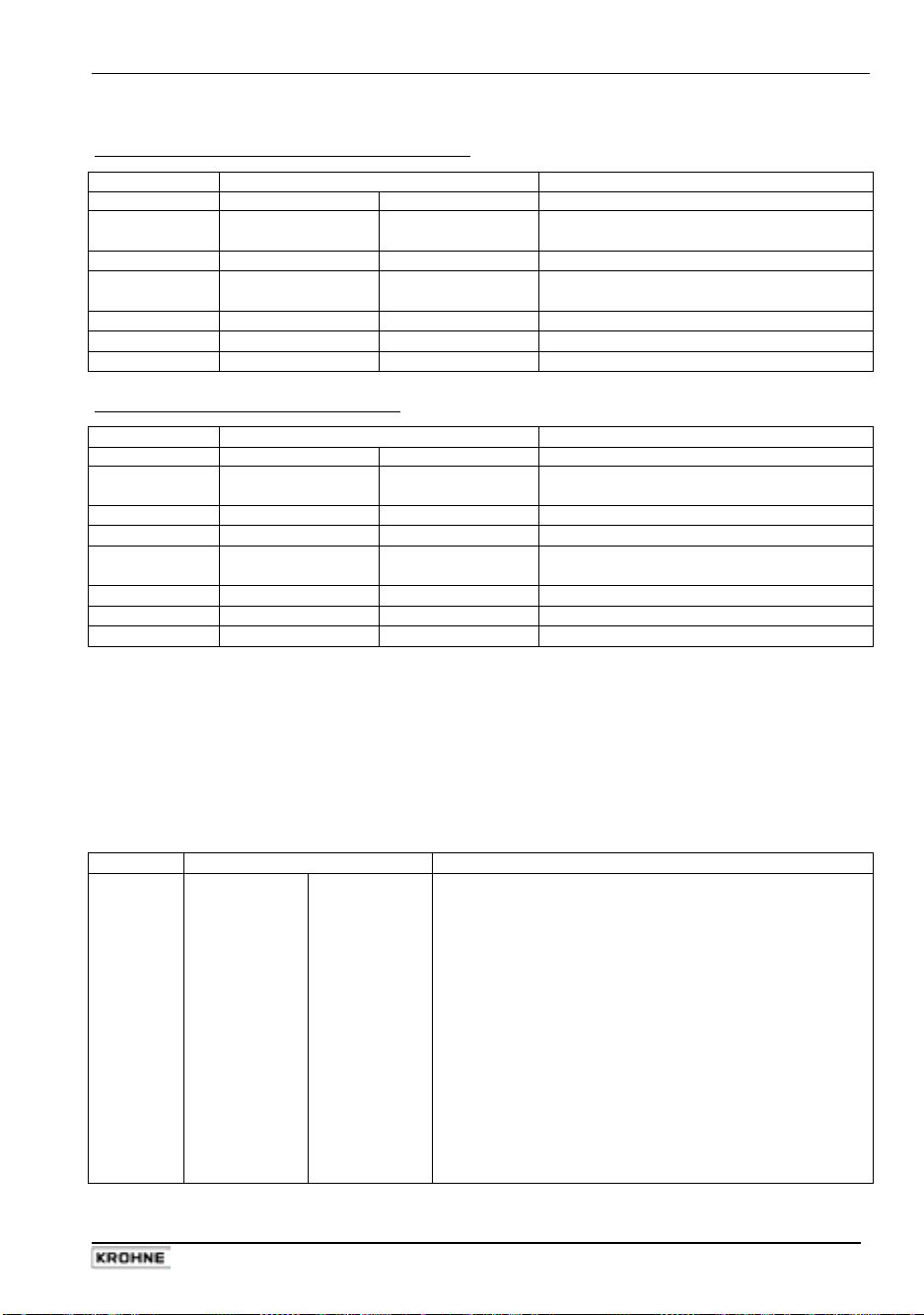
Part B IFC 110 F Signal converter Sect. 4.6
4.6 Resetting the totalizer and deleting error messages, RESET/QUIT menu
Delete error messages in RESET/QUIT menu
Key Display Description
- - - - - - - - - - - - / - - - Measuring mode
↵
↑ →
→
↑
↵
↵
CodE 2 - - Key-in entry code 2 for RESET/QUIT menu:
ERROR QUIT. Menu for error acknowledgement
QUIT. NO Do not delete error messages,
QUIT. YES Delete error messages
ERROR QUIT. Error messages deleted.
- - - - - - - - - - - - / - - - Return to measuring mode
↑ →
press ↵ twice to return to measuring mode.
Reset totalizer in RESET/QUIT menu
Key Display Description
- - - - - - - - - - - - / - - - Measuring mode
CodE 2 - - Key-in entry code 2 for RESET/QUIT menu:
↑ →
↑
→
↑
↵
↵
ERROR QUIT. Menu for error acknowledgement
TOTAL.RESET Menu for resetting totalizer
RESET NO Do not reset totalizer,
RESET YES Reset totalizer
TOTAL.RESET Totalizer is reset
- - - - - - - - - - - - / - - - Return to measuring mode
↑ →
press ↵ twice to return to measuring mode
4.7 Examples of signal converter settings
In the following example the cursor or flashing part of the display is shown in bold characters.
• Change measuring range of current output and value for error messages (Fct. 1.05):
• Change measuring range from 04-20 mA to 00-20 mA
• Change value for error messages from 0 mA to 22 mA
Key Display Description
→
Fct. 1.00 OPERATION
→
4x ↑
→
→ ↵
→
2x ↑
↵
→
↑
↵
↵
↵
↵
If ”YES” is selected in Fct. 3.04 ENTRY
CODE, enter the 9-digit entry CODE 1:
Fct. 1.01 FULL SCALE
Fct. 1.05 CURRENT I
FUNCT. I
RANGE I
04-20 mA old current range
00-20 mA new current range
I ERROR
0 mA old value for error messages
22 mA new value for error messages
Fct. 1.05 CURRENT I
Fct. 1.00 OPERATION
STORE YES
- - - - - - - - - - - - / - - - Measuring mode with new current output data
→ → → ↑ ↑ ↑ ↵ ↵ ↵
IFC 110 F 39
05/2003
Page 40

Sect. 5.1 Part B IFC 110 F Signal converter
5 Description of functions
5.1 Full-scale range Q
100%
Fct. 1.01 FULL SCALE
Press → key
Select unit for full-scale range Q
• m³/h
• Liter/Sec
• US.Gal/min
(cubic metres per hour)
(litres per second)
(US gallons per minute)
100%
• User-defined unit, factory setting = ”Liter/h” (litres per hour) or “US MGal/day”,
see Section 5.14
Select with ↑ and ↓ keys.
Use → key to change to numerical setting, 1st number (cursor) flashes.
Set full-scale range Q
100%
The setting range depends on the meter size (DN) and the flow velocity (v):
= DN² x v
Q
min
π
4
min
Q
π
= DN² x v
max
4
(refer to flow table in Section 10.2)
max
Nom. diameter/meter size
• DN 2.5 – 1200 / 1/10” – 48”:
0.0053 – 48 860 m³/h
0.0237 – 218 560 US.Gal/min
• DN 1300 – 3000 / 52” – 120”:
(refer to Section 8.6) 6415 – 1 366 000 US.Gal/min
1435 – 305 360 m³/h
Change flashing number (cursor) with ↑ and ↓ keys.
Use → and ← keys to shift cursor 1 place to right or left.
Flashing numbers (cursor) can also be directly set with the 10-key keyboard.
Press ↵ key to return to Fct. 1.1 FULL SCALE
Please note that if ”VALUE P” or ”VALUE P2” is displayed after pressing ↵ key:
PULSE/VOL. is set in Fct. 1.06 PULS P and/or in Fct. 1.07 PULS 2 A1, subfunction ”SELECT P”
and/or ”SELECT P2”. Due to the changed full-scale range Q
, the output frequency (F) of the
100%
pulse outputs is either exceeded or not reached:
= F
P
min
min
/ Q
100%
P
max
= F
max
/ Q
100%
Change pulse value accordingly, see Section 5.07 Pulse output P, Fct. 1.06 and/or 2nd pulse
output A1, Fct. 1.07.
5.2 Time constant
Fct. 1.02 TIMECONST.
Press → key
Select
• ALL
• ONLY I
(applies to display and all outputs)
(applies only to display, current and status outputs)
Select with keys ↑ and ↓.
Press ↵ key to change to numerical setting, 1st number (cursor) flashes.
Set numerical value
• 0.2 - 99.9 s
(seconds)
Change flashing number (cursor) with keys ↑ and ↓ .
Use → and ← keys to shift cursor 1 place to right or left.
Flashing numbers (cursor) can also be directly set with the 10-key keyboard.
Press ↵ key to return to Fct. 1.02 TIMECONST.
40 IFC 110 F
05/2003
Page 41

Part B IFC 110 F Signal converter Sect. 5.3
5.3 Low-flow cutoff SMU
Fct. 1.03 L.F. CUTOFF
Press → key
Select
• OFF
• PERCENT
(fixed tripping points: ON = 0.1 % / OFF = 0.2 %)
(variable tripping points: ON = 1 - 19 % / OFF = 2 - 20 %)
Select with keys ↑ and ↓ (only if PERCENT is selected).
1st number (cursor) flashes.
Setting the numerical value when ”PERCENT” is selected
• 01 to 19
• 02 to 20
(cutoff ”ON” value, left of hyphen)
(cutoff ”OFF” value, right of hyphen)
Change flashing number (cursor) with keys ↑ and ↓ .
Use → and ← keys to shift cursor 1 place to right or left.
Flashing numbers (cursor) can also be directly set with the 10-key keyboard.
Press ↵ key to return to Fct. 1.03 L.F. CUTOFF.
Note: the cutoff ”OFF” value must be greater than the cutoff ”ON” value.
5.4 Display
Fct. 1.04 DISPLAY
Press → key
→ DISP. FLOW = select unit for display of flow rate, press → key
• NO DISP
• m³/h
• Liter/Sec
• US.Gal/min
(no display)
(cubic metres per hour)
(litres per second)
(US gallons per minute)
• User-defined unit, factory setting = ”Liter/h” (litres per hour) or ”US MGal/day”,
see Section 5.14
• PERCENT
• BARGRAPH
(percentage display)
(numerical value and bar graph display in %)
Select with ↑ and ↓ keys.
Press ↵ key to change to subfunction ”DISP. TOTAL.”.
→ DISP. TOTAL. = select unit for totalizer display, press → key
• NO DISP.
• OFF
• + TOTAL. • – TOTAL. • +/– TOTAL.
(no display)
(internal totalizer switched off)
• SUM. (Σ)
• ALL (sequential)
Select with ↑ and ↓ keys.
Press ↵ key to change to display unit setting.
• m³
• Liter
• US.Gal
• User-defined unit, factory setting = ”Liter” (litres) or ”US MGal/day”, see Section 5.14
(cubic metres)
(litres)
(US gallons)
Select with ↑ and ↓ keys.
Use → key to change to totalizer format setting.
IFC 110 F 41
05/2003
Page 42

Sect. 5.5 Part B IFC 110 F Signal converter
Setting of totalizer format
• Auto (exponent notation)
• # . ####### • ##### . ###
• ## . ###### • ###### . ##
• ### . ##### • ####### . #
• #### . #### • ########
Select with ↑ and ↓ keys.
Press ↵ key to change to subfunction ”DISP. MSG.”.
→ DISP. MSG. = additional messages desired in measuring mode, press → key
• NO
• YES
(no additional messages)
(display additional messages, e.g. errors, in sequence with measured values)
Select with ↑ and ↓ keys.
Press ↵ key to return to Fct. 1.04 DISPLAY
Note: ”BUSY” is displayed in measuring mode when all displays are set to ”NO DISP.” or ”NO”.
Sequencing of displays is automatic. In measuring mode, however, keys - and ¯ can be used
for manual sequencing. Return to automatic sequencing after approx. 3 minutes.
Please refer to Section 2.7 ”Factory settings”
5.5 Internal electronic totalizer
The internal electronic totalizer counts in m³ regardless of the unit set in Fct. 1.04, subfunction
”DISP. FLOW”.
The counting range depends on the meter size and has been selected such that the totalizer will
count for at least 1 year without overflow.
Meter size
DN mm Inch in m³ US Gal equivalent
2.5 - 50 1/10 - 2 999 999.99999999 0 - 264 172 052.35800
65 - 200 21/2 - 8 9 999 999.9999999 0 - 2 641 720 523.5800
250 - 600 10 - 24 99 999 999.999999 0 - 26 417 205 235.800
700 -1000 28 - 40 999 999 999.99999 0 - 264 172 052 358.00
Only part of the totalizer count is shown in the display as it is not possible to display a 14-digit
number. Unit and format of the display are freely selectable. Refer to Fct. 1.04, subfunction ”DISP.
TOTAL.” and Section 5.4 to determine which part of the count is to be displayed. Display overflow
and totalizer overflow are independent of one another.
Example
Internal count 0000123 . 7654321 m³
Format, display unit
XXXX . XXXX liter
Internal count in unit 0123765 . 4321000 liter
Displayed 3765 . 4321 liter
Counting range
42 IFC 110 F
05/2003
Page 43

Part B IFC 110 F Signal converter Sect. 5.6
5.6 Internal power supply (E+/E-) for connected loads
Passive loads connected to the outputs and inputs can be fed by means of the internal power
supply (terminals E+/E-).
U = 24 V DC (observe polarity)
Ri =
I
approx. 15 Ω
100 mA
≤
Connection diagrams, see Section 2.6.
5.7 Current output I
Fct. 1.05 CUR. OUTP. I
Press → key
→ FUNCT. I = select function for current output, press → key
• OFF
• + DIR.
• – DIR.
• 2 DIR.
(switched off, no function)
(measurement in one direction, refer to selection of main flow direction in
}
Fct. 3.02 FLOW METER, subfunction ”FLOW DIR.”)
(2 flow directions, F/R mode, forward/reverse)
Select with ↑ and ↓ keys.
Press ↵ key to change to subfunction ”RANGE I”.
Exception:
→ REV. RANGE = select full-scale range for reverse flow
when ”OFF” is selected, return to Fct. 1.05 CUR. OUTP. I.
When ”2 DIR.” is selected, change to subfunction ”REV. RANGE”.
(only displayed when ”2 DIR.” is selected in ”FUNCT. I” above)
Press → key
• 100 PCT.
• PERCENT
(same full-scale range Q
(adjustable range) Setting range 005 - 150 % of Q100% (see Fct. 1.01)
as forward flow, see Fct. 1.01)
100%
Select with ↑ and ↓ keys.
Press → key to change to numerical setting.
Change flashing number (cursor) with keys ↑ and ↓. Use → and ← keys to shift cursor 1 place
to right or left.
Flashing numbers (cursor) can also be directly set with the 10-key keyboard.
Press ↵ key to change to subfunction ”RANGE I”.
→ RANGE I = select the measuring range, press → key
• 0 - 20 mA
• 4 - 20 mA
• mA (any value)
(value I
0%
< I
100%
fixed ranges
}
0% – I100%
I
!) 0-16 mA 4-20 mA
Press → key to change to numerical setting.
Select with ↑ and ↓ keys.
Change flashing number (cursor) with keys ↑ and ↓ . Use → and ← keys to shift cursor
1 place to right or left.
Flashing numbers (cursor) can also be directly set with the 10-key keyboard.
Press ↵ key to change to subfunction ”I ERROR”
IFC 110 F 43
05/2003
Page 44

Sect. 5.7 Part B IFC 110 F Signal converter
→ I ERROR = set the error value, press → key
• 22 mA
• 0.0 - I
0%
(fixed value)
mA
(variable value, only variable when I0% ≥ 1 mA, see ”RANGE I” above)
Select with ↑ and ↓ keys.
Change flashing number (cursor) with keys ↑ and ↓ . Use → and ← keys to shift cursor
1 place to right or left.
Flashing numbers (cursor) can also be directly set with the 10-key keyboard.
Press ↵ key to return to Fct. 1.05 CUR. OUTP. I
Please refer to Section 2.7 ”Factory settings”
Refer to Section 2.6 for connection diagrams and to Section 5.16 for characteristics.
5.8 Pulse outputs P and A1
Pulse output P 2nd pulse output A1
for ... electronic totalizer electromagnetic or
electronic totalizers
Terminals
F
at full-scale range Q
max
F
at full-scale range Q
min
Max. switching current
200 mA / DC polarized
(see Section 6.3)
Remark
in Fct. 3.07 HARDWARE,
subfunction ”Terminal A1”
PLEASE NOTE:
check that output terminal ”A1” is defined as pulse output in
Fct. 3.07 “HARDWARE”, see Sections 2.2 and 5.17.
Fct. 1.06 PULS P
Press → key
Fct. 1.07 PULS2 A1
and / or
→ FUNCT. P = select function for pulse output, press → key
• OFF
• + DIR.
• – DIR.
• 2 DIR.
(switched off, no function)
(measurement in one direction, refer to selection of main flow direction in
}
Fct. 3.02 FLOW METER, subfunction ”FLOW DIR.”)
(2 flow directions, F/R mode, forward/reverse)
Select with ↑ and ↓ keys.
Press ↵ key to change to subfunction ”SELECT P”.
Exception: when ”OFF” is selected, return to Fct. 1.06 PULS P or Fct. 1.07 PULS2 A1.
→ SELECT P = select pulse type, press → key
• PULSE/VOL.
• PULSE/TIME
(pulses per unit volume, flow)
(pulses per unit time for 100 % flow)
Select with ↑ and ↓ keys.
Press ↵ key to change to subfunction ”PULSWIDTH”.
P and P
10,000 pulses/s 50 pulses/s
100%
10 pulses/h 10 pulses/h
100%
A1 and A ⊥
30 mA / AC or DC 100 mA / AC or DC
– ”PULSOUTP.” must be selected
Press → key
44 IFC 110 F
05/2003
Page 45

Part B IFC 110 F Signal converter Sect. 5.8
→ PULSWIDTH = select pulse width, press → key
• AUTO
• SYM.
• SEC.
(automatic = 50 % of cycle duration of 100 % output frequency)
(symmetric = pulse duty factor 1:1 across entire range)
(variable) setting range 0.01 - 1.00 SEC
Select with ↑ and ↓ keys.
Press → key to change to numerical setting.
Change flashing number (cursor) with keys ↑ and ↓ . Use → and ← keys to shift cursor
1 place to right or left.
Flashing numbers (cursor) can also be directly set with the 10-key keyboard.
Press ↵ key to change to subfunction ”VALUE P” and/or ”VALUE P2”.
→ VALUE P = set pulse value per unit volume
only appears when ”PULSE/VOL.” is selected in ”SELECT P”, press → key
• XXXX PulS/m³
• XXXX PulS/litre
• XXXX PulS/US.Gal
• XXXX PulS/user-defined unit, factory setting = ”Liter” or ”US MGal/day”, see Section 5.14
Select with ↑ and ↓ keys.
Press → key to change to numerical setting, 1st number (cursor) flashes.
Set numerical value
• XXXX
(setting range depends on pulse width and full-scale range:
= F
/ Q
P
min
min
100%
P
max
= F
max
/ Q
100%
)
Change flashing number (cursor) with keys ↑ and ↓ . Use → and ← keys to shift cursor
1 place to right or left.
Flashing numbers (cursor) can also be directly set with the 10-key keyboard.
Press ↵ key to return to Fct. 1.06 PULS P or to Fct. 1.07 PULS2 A1.
or
→ VALUE P = set pulse value per unit time
only appears when ”PULSE/TIME” is selected in ”SELECT P”, press → key
• XXXX PulSe/Sec
• XXXX PulSe/min
• XXXX PulSe/h
• XXXX PulSe/user-defined unit, factory setting = ”h” or ”day”, see Section 5.14
Select with ↑ and ↓ keys.
Press → key to change to numerical setting, 1st number (cursor) flashes.
Set numerical value
• XXXX
(setting range depends on pulse width)
Change flashing number (cursor) with keys ↑ and ↓ . Use → and ← keys to shift cursor
1 place to right or left.
Flashing numbers (cursor) can also be directly set with the 10-key keyboard.
Press ↵ key to return to Fct. 1.06 PULS P or to Fct. 1.07 PULS2 A1.
Please refer to Section 2.7 ”Factory settings”.
Refer to Section 2.6 for connection diagrams and to Section 5.16 for characteristics.
IFC 110 F 45
05/2003
Page 46

Sect. 5.9 Part B IFC 110 F Signal converter
5.9 Status outputs A1 / A2 and D1 / D2
PLEASE NOTE:
Connection diagrams see Section 2.6.
Status outputs A1 A2 D1 D2
Select Fct _ . _ _
then press → key
Terminals
Max. switching
current
Remark
PLEASE NOTE:
Select function for status outputs, press → key
• ALL ERROR
• FATAL.ERROR
• OFF
• ON
• SIGN I
• SIGN P/P2
• OVERFL. I
• OVERFL. P/P2
• INVERS. A1
• INVERS. D1
• EMPTY PIPE
• AUTO. RNG.
(= high to low range ratio, 1:20 to 1:1.25, value must be higher than that of
Fct. 1.03 L.F. CUTOFF), see Section 5.20.
• FULL SCALE, see Section 5.19.
Select flow direction (characteristic) for full-scale range
• + DIR. • – DIR. • 2 DIR.
Define full-scale range
XXX – YYY
0 – 150% 0 – 150%
Press ↵ key to change to numerical setting, 1st number (cursor) flashes.
Change flashing number (cursor) with keys ↑ and ↓ . Use → and ← keys to shift cursor
1 place to right or left.
Flashing numbers (cursor) can also be directly set with the 10-key keyboard.
Press ↵ key to return to Fct. 1.07, 1.08, 1.09 or 1.10 for status outputs A1, A2, D1 or D2.
1.07 1.08 1.09 1.10
A1 / A⊥ A2 / A⊥ D1 / D⊥ D2 / D⊥
• 100 mA/AC
or DC
• 200 mA/DC
polarized
see Section 6.3
”STATUSOUTP.”
must be selected
in Fct. 3.07
HARDWARE,
subfunction
”TERMINALS”.
(indicate all errors)
(only indicate fatal errors)
(switched off, no function)
(signals the operation of the flowmeter)
F/R mode
}
exceeding
}
output ranges
(switches output A2 inverse to A1. A1 and A2 then operate as
change-over elements with common centre grounding contact A⊥. Only
available when status output is selected in Fct. 3.07 ”TERM. A1”.)
(switches output D2 inverse to D1. D1 and D2 then operate as
change-over elements with common centre grounding contact D⊥).
(signals that measuring tube is empty, only with option ”empty tube
detection”)
(automatic range change) Setting range
normally open contact:
normally closed contact:
hysteresis:
100 mA/AC 100 mA/AC 100 mA/AC
– – –
dynamic behaviour
of outputs see Fct. 1.02, Sect. 5.2 ”Time constant”
I = ONLY I
}
P/P2 = ALL
5 - 80 PERCENT
Select with ↑ and ↓ keys.
XXX > YYY
XXX < YYY
difference between XXX and YYY.
46 IFC 110 F
05/2003
Page 47
Part B IFC 110 F Signal converter Sect. 5.10
Characteristic of status outputs Switch open Switch closed
OFF (switched off)
ON (e.g. operation indicator)
SIGN I (F/R mode) forward flow reverse flow
SIGN P/P2 (F/R mode) forward flow reverse flow
FULL SCALE (full-scale indicator)
AUTO. RNG. (autom. range change)
OVERFL. I (I range exceeded)
OVERFL. P/P2 (P range exceeded)
ALL ERROR (all errors)
FATAL.ERROR (only fatal errors)
INVERS A1: status output A2 . . .
INVERS D1: status output D2 . . .
EMPTY PIPE (empty tube
identification option)
For factory settings please refer to Section 2.7.
power supply OFF power supply ON
inactive active
high range low range
current output O.K. cur. output range exceeded
pulse output O.K. pulse output range exceeded
error no error
error no error
when A1 is closed when A1 is open
when D1 is closed when D1 is open
when measuring tube
is empty
no function
when measuring tube
is full
5.10 Control inputs C1 and C2
Fct. 1.11 CONTROL C1
Press → key
Select function for the control inputs
• OFF
• OUTP. HOLD
• OUTP. ZERO
• TOTAL. RESET
• ERROR. RESET
• EXT. RNG.
Setting range
1:20 to 1:1.25, value must be greater than that of Fct. 1.03 L.F. CUTOFF)
Press ↵ key to change to numerical setting, 1st number (cursor) flashes.
Change flashing number (cursor) with keys ↑ and ↓ . Use → and ← keys to shift cursor
1 place to right or left.
Flashing numbers (cursor) can also be directly set with the 10-key keyboard.
Press ↵ key to return to Fct. 1.11 CONTROL C1 or to Fct. 1.12 CONTROL C2.
Please refer to Section 2.7 for factory settings.
Connection diagram see Section 2.6.
Fct. 1.12 CONTROL C2
(switched off, no function)
(hold output values) Functions also act on
(set outputs to ”min. values”)
(reset totalizer)
(acknowledge/delete error messages)
(external range change for automatic range change, see Sect. 5.20.
and/or
Press → key
, press ↑ or ↓ key
}
display and totalizer
5 - 80 PERCENT = low to high range ratio
IFC 110 F 47
05/2003
Page 48

Sect. 5.11 Part B IFC 110 F Signal converter
5.11 Language
Fct. 3.01 LANGUAGE
Press → key
Select language for texts in display
• D
• GB/USA
• F
(German)
(English)
(French)
• S
(Swedish)
• Other languages on request
Select with ↑ and ↓ keys.
Press ↵ key to return to Fct. 3.01 LANGUAGE.
5.12 Entry code
Fct. 3.04 ENTRY CODE
Press → key
Select
• NO
• YES
Select with ↑ and ↓ keys.
Press ↵ key to return to Fct. 3.04 ENTRY CODE.
(no code, enter setting mode by pressing → key)
(enter setting mode by pressing → key and Code 1: → → → ↵ ↵ ↵ ↑ ↑ ↑)
48 IFC 110 F
05/2003
Page 49

Part B IFC 110 F Signal converter Sect. 5.13
5.13 Flow sensor
Fct. 3.02 FLOW METER
Press → key
→ DIAMETER = set meter size (see instrument nameplate), press → key
Select size from table of meter sizes:
• DN 2.5 – 1200 equivalent to 1/10 - 48 inch
• DN 1300 – 3000 equivalent to 52 - 120 inch, see Section 8.6.
Select with ↑ and ↓ keys.
Press ↵ key to change to subfunction ”FULL SCALE”.
→ FULL SCALE = set full-scale range, press → key
Set as described in Section 5.1.
Press ↵ key to change to subfunction ”GK VALUE”.
Please note that if ”VALUE P” or ”VALUE P2” is displayed after pressing ↵ key:
PULSE/VOL. is set in Fct. 1.06 PULS P and/or in Fct. 1.07 PULS 2 A1, subfunction ”SELECT P”
and/or ”SELECT P2”. Due to the changed full-scale range Q
, the output frequency (F) of the
100%
pulse outputs is either exceeded or not reached:
= F
P
min
min
/ Q
100%
P
max
= F
max
/ Q
100%
Change pulse value accordingly, see Section 5.08 Pulse output P, Fct. 1.06
and/or 2nd pulse output A1, Fct. 1.07.
→ GK VALUE = set flow sensor constant GK, press → key
• 1.0000 - 9.9999 (note information on instrument nameplate, do not change setting)
Change flashing number (cursor) with keys ↑ and ↓ .
Use → and ← keys to shift cursor 1 place to right or left.
Flashing numbers (cursor) can also be directly set with the 10-key keyboard.
Press ↵ key to change to subfunction ”FIELD FREQ.”
→ FIELD FREQ. = set magnetic field frequency, press → key
• 1/2 • 1/6
• 1/18 • 1/36
(1/2, 1/6, 1/18 or 1/36 of power frequency, see instrument nameplate,
do not change setting, exceptions
see Sections 6.4-6.10)
Select with ↑ and ↓ keys.
Press ↵ key to change to subfunction ”FLOW DIR.”
(for DC instruments change to subfunction ”LINE FREQ.”).
→ LINE FREQ. = set power frequency customary in country
where instrument is used, press → key
(Please note: only applies to instruments with DC power unit)
• 50 Hz
• 60 Hz
→ FLOW DIR. = set flow direction, press → key
• + DIR.
• - DIR.
Select with ↑ and ↓ keys.
Press ↵ key to change to subfunction ”FLOW DIR.”.
(for identification of flow direction see ”+” arrow on flow sensor;
F/R mode: identification of ”positive” flow direction)
Select with ↑ and ↓ keys.
Press ↵ key to return to Fct. 3.02 FLOW METER.
Zero check, see Fct. 3.03 and Section 7.1.
Please refer to Section 2.7 ”Factory settings”.
IFC 110 F 49
05/2003
Page 50

Sect. 5.14 Part B IFC 110 F Signal converter
5.14 User-defined units
Fct. 3.05 USER UNIT
Press → key
→ TEXT VOL. = set text for user-defined flow unit, press → key
• Liter
(max. 5 characters, factory setting = ”Liter” or ”US MGal”)
Characters which can be assigned to each place:
A-Z, a-z, 0-9 or ”–”
(= blank character).
Change flashing number (cursor) with keys ↑ and ↓.
Use → and ← keys to shift cursor 1 place to right or left.
Press ↵ key to change to subfunction ”FACT. VOL.”.
→ FACT. VOL. = set factor FM for volume, press → key
• 1.00000 E+3
(factory setting ”1000” / Factor F
= volume per 1 m³)
M
Setting range: 1.00000 E-9 to 9.99999 E+9 ( = 10-9 bis 10+9)
Change flashing number (cursor) with keys ↑ and ↓.
Use → and ← keys to shift cursor 1 place to right or left.
Press ↵ key to change to subfunction ”TEXT TIME”.
→ TEXT TIME = set text for required time, press → key
• h
(max. 3 places, factory setting = ”h”/hours or ”day”)
Characters which can be assigned to each place:
A-Z, a-z, 0-9 or ”–” (= blank character).
Change flashing number (cursor) with keys ↑ and ↓.
Use → and ← keys to shift cursor 1 place to right or left.
Press ↵ key to change to subfunction ”FACT. TIME”.
→ FACT. TIME = set factor FT for time, press → key
• 3.60000 E+3
(factory setting ”3600” / set factor FT in seconds)
Setting range: 1.00000 E-9 to 9.99999 E+9 ( = 10-9 bis 10+9)
Change flashing number (cursor) with keys ↑ and ↓.
Use → and ← keys to shift cursor 1 place to right or left.
Press ↵ key to return to Fct. 3.05 USER UNIT
Flashing numbers (cursor) can also be directly set with the 10-key keyboard.
Factors for volume F
Volumetric unit Text example Factor FM Setting
Cubic metres
Liter
Hectolitres
Decilitres
Centilitres
Millilitres
US gallons
Millions US gallons
Imperial gallons
Mega imperial gallons
Cubic feet
Cubic inches
US barrels liquid
US barrels ounces
Factors for time FT (factor F
Time unit Text example Factor FT (seconds) Setting
Seconds
Minutes
Hours
Day
Year (=365 days)
(factor FM = volume per 1 m³)
M
m³
Liter
h Lit
d Lit
c Lit
m Lit
USGal
USMG
GBGal
GBMG
Feet3
inch3
US BaL
US BaO
sec
min
h
DAY
YR
in seconds)
T
1.0
1 000
10
10 000
100 000
1 000 000
264.172
0.000264172
219.969
0.000219969
35.3146
61 024.0
6.28982
33 813.5
1
60
3 600
86 400
31 536 000
1.00000 E+0
1.00000 E+3
1.00000 E+1
1.00000 E+4
1.00000 E+5
1.00000 E+6
2.64172 E+2
2.64172 E-4
2.19969 E+2
2.19969 E-4
3.53146 E+1
6.10240 E+4
6.28982 E+0
3.38135 E+4
1.00000 E+0
6.00000 E+1
3.60000 E+3
8.64000 E+4
3.15360 E+7
50 IFC 110 F
05/2003
Page 51

Part B IFC 110 F Signal converter Sect. 5.15
5.15 F/R mode, forward/reverse flow measurement
• Refer to Section 2.6 for electrical connection of outputs.
• Define direction of forward flow, see Fct. 3.02, subfunction ”FLOW DIR.”:
in conjunction with F/R operation, this is where to set the direction of the forward flow.
”+” means the same direction as shown by the arrow on the flow sensor.
”-” means the opposite direction.
• Set one of the status outputs to ”SIGN I”, ”SIGN P” or ”SIGN P2”, see Fct. 1.08-1.10 (1.07).
Dynamic behaviour of outputs in case of ”SIGN I, P or P2” see Section 5.8.
• Current and/or pulse outputs must be set to ”2 DIR.”, see Fct. 1.05, 1.06 and 1.07,
subfunctions ”FUNCT. I”, ”FUNCT. P” and ”FUNCT. P2”.
5.16 Output characteristics
I
I
0%
I
100%
P
P
QF
Q
Q
S
100%
R
100%
current output
0 or 4 mA
20 mA
pulse outputs P and A1 (P2)
pulses at Q
, full-scale range
100%
1 flow direction, forward flow in F/R mode
reverse flow in F/R mode
full-scale range
status outputs A1, A2, D1 and D2
switch open
switch closed
1 flow direction 2 flow directions
IFC 110 F 51
05/2003
Page 52

Sect. 5.17 Part B IFC 110 F Signal converter
5.17 Applications
Fct. 3.06 APPLICAT.
Press → key twice
Set flow characteristics, select with ↑ or ↓ keys
• STEADY
• PULSATING
Press ↵ key to change to subfunction ”ADC GAIN”.
Set ADC GAIN, select with ↑ or ↓ keys
• AUTO
• 10
• 30
• 100
Press ↵ key three times to return to Fct. APPLICAT.
Do not change the settings of subfunctions ”SPEC. FILT.”, ”LIMIT VAL.” and ”LIMIT CNT.” as
these functions are needed to obtain steady signals for display and outputs for special
applications, see Section 6.6.
(steady flow)
(pulsating flow, e,g, caused by reciprocating pumps,
refer to Sections 6.5 to 6.10 ”Special applications”)
(for homogeneous process liquids, low pulsation)
(for high solids contents or extremely pulsating flows)
(for solids contents or pulsating flows)
(high resolution even at low flows)
5.18 Hardware settings
Fct. 3.07 HARDWARE
Press → key
Define function of terminal A1, press → key
• PULSOUTP.
• STATUSOUTP.
Carry out selfcheck during measurement? Press → key
• NO • YES
What is checked?
Errors are only displayed when ”YES” is selected in Fct. 1.04 DISPLAY, subfunction ”DISP.
MSG.”. After acknowledging/deleting the errors in the ERROR/QUIT menu (see Section 4.6), the
tests described in a) and b) above are re-started. Test duration 4 to 20 minutes.
Select field current supply, press → key
• INTERNAL
• EXTERNAL
Press ↵ key to return to Fct, 3.07 HARDWARE.
(= pulse output)
(= status output)
Select with ↑ or ↓ keys, press ↵ key to change to ”Field current”.
ADC gain and other parameters are continuously checked for their
permissible values and deviations.
(DN 2.5–1600 / 1/10”–64”)
(see Section 8.6)
Select with ↑ or ↓ keys,
}
press ↵ key to change to ”Selfcheck”
Select with ↑ or ↓ keys,
}
52 IFC 110 F
05/2003
Page 53

Part C Special applications, functional checks, service, and order numbers Sect. 6.1
5.19 Limit switches
Fct. 1.07 - 1.10 Status outputs A1, A2, D1 or D2
(Define operating mode of output terminals A1, see Section 5.18)
Press → key
Press ↑ key as often as required to set one of the status outputs to ”TRIP. POINT”
Press → key to change to ”Characteristic” (flow direction).
Select:
• + DIR.
Press ↵ key to change to numerical setting, 1st number (cursor) flashes.
Change flashing number (cursor) with keys ↑ and ↓. Use → and ← keys to shift cursor
1 place to right or left.
• Display:
• Setting ranges:
• Switching behaviour (NO/NC contact) and hysteresis are adjustable.
NC contact XXX value > YYY value NC contact XXX value < YYY value
Switch closes when flow exceeds XXX value Switch opens when flow exceeds YYY value
Example: XXX = 55% Example: XXX = 45%
YYY = 45% YYY = 55%
hysteresis = 10% hysteresis = 10%
• – DIR.
• 2 DIR.
XXX – YYY
Select with ↑ or ↓ keys
}
XXX value = 0 – 150% of Q
YYY value = 0 – 150% of Q
hysteresis ≥ 1% (= difference between XXX and YYY values)
100%
100%
Please note:
05/2003
if two status outputs (e.g. D1 and D2) are activated
it is possible to have e.g. min. and max. values signalled.
IFC 110 F 53
Page 54

Sect. 6.4 Part B IFC 110 F Signal converter
5.20 Range change
Automatic range change by status output
Fct. 1.07 - 1.10 Status outputs A1, A2, D1 or D2
(Define operating mode of output terminal A1, see Section 5.18)
Press → key
Press ↑ key as often as required to set one of the status outputs to automatic range change
”AUTO. RNG.”
Press ↵ key to change to numerical setting, 1st number (cursor) flashes.
Change flashing number (cursor) with keys ↑ and ↓. Use → and ← keys to shift cursor
1 place to right or left.
Flashing numbers (cursor) can also be directly set with the 10-key keyboard.
Setting range:
5 – 80 PERCENT of Q
100%
Press ↵ key to return to Fct. 1.07 - 1.10, status outputs A1, A2, D1 or D2.
External range change by control input
Fct. 1.11 or 1.12 Control inputs C1 or C2
Press → key
Press ↑ key as often as required to set one of the control inputs C1 or C2 to range change
”EXT. RNG.”
Press ↵ key to change to numerical setting, 1st number (cursor) flashes.
Change flashing number (cursor) with keys ↑ and ↓. Use → and ← keys to shift cursor
1 place to right or left.
Flashing numbers (cursor) can also be directly set with the 10-key keyboard.
Setting range:
5 – 80 PERCENT of Q
100%
Press ↵ key to return to Fct. 1.11 or 1.12, control inputs C1 or C2.
(= low to high range ratio 1:20 to 1:1.25)
(= low to high range ratio 1:20 to 1:1.25)
54 IFC 110 F
05/2003
Page 55

Part C Special applications, functional checks, service, and order numbers Sect. 6.1
6 Special Applications, Functional Checks, Service and Order Numbers
6.1 Use in hazardous areas
6.1.1 General
Signal converters of type IFC 110 F - EEx are type tested as associated electrical apparatus in
compliance with European Directive 94/9/EG (ATEX 100a) in conformity with European Standards
EN 50 014 / EN 50 020.
The EC type examination certificate has been issued by the Physikalisch-Technische
Bundesanstalt (PTB) under: PTB 02 ATEX 2163 X
6.1.2 Main safety features
Both generation of the intrinsically safe electrode circuit and also protection of the non-intrinsically
safe field circuit by fusible links form integral parts of the IFC 110 F - EEx signal converter.
• Category / Zone
IFC 110 F - EEx signal converters are associated electrical apparatus required to be installed
outside the hazardous area.
The intrinsically safe electrode circuit is designed in Category 2 for use in Zone 1.
• Types of protection
The electrode circuit is designed in Intrinsic Safety EEx ib IIC type of protection.
The non-intrinsically safe field circuit must be installed inside the hazardous area using a type
of protection conforming to European Standard (e.g. Increased Safety "e").
Power supply and signal inputs / outputs are non-intrinsically safe.
• Field current fuse protection
The field circuit is fuse-protected in the signal converter IFC 110F – EEx by two fusible links on
the FSV circuit board (TR5, 160 mA F).
• Safety-relevant type code
The following code is used for type designation:
IFC
1 2 3 4 5 6
1 Electromagnetic signal converter
2 Type series
3 Field housing for “remote” measuring systems
4 Marking – no effect on explosion protection
S Special version for -40 °C
… others as required
5 Approval to European standard
6 Explosion-protected equipment
Important, please note!
• Observe the directions, regulations and electrical data specified in the EC type
examination certificate, see Section 13.
• In addition to the regulations for power installations (VDE 0100), pay particular
attention to the regulations specified in EN 60079-14 “Electrical installations in
hazardous areas".
• Assembly, installation, commissioning and maintenance may only be carried out by
”personnel trained in explosion protection“!
110 F / … - E Ex
IFC 110 F 55
05/2003
Page 56

Sect. 6.1 Part C Special applications, functional checks, service, and order numbers
6.1.3 Installation and electrical connection
Type IFC 110 F - EEx signal converters are type tested as associated electrical apparatus.
They are installed outside the hazardous area.
The PE/PA connection (housing) must have protective bonding with the potential of the hazardous
area (PA).
Insulation ratings
The insulation of signal converters Type IFC 110 F - EEx is rated in conformity with
VDE 0110-1, equivalent to IEC 664-1, and the following rated values have been taken
into consideration:
• overvoltage category for the line circuit: III
• overvoltage category for the signal and measuring circuits: II
• insulation pollution degree: 2
Important, please note without fail!
• The buffer barrier for the intrinsically safe electrode circuit is an integral part of the
IFC 110 F - EEx signal converter and is safety galvanically isolated.
• The cable entry for the interconnecting cable of the intrinsically safe electrode circuit
is marked in light blue.
• The terminals of the intrinsically safe electrode circuit may only be connected to
intrinsically safe circuits, even if the device is operated in the non-hazardous area.
• Electrical connection between front panel and potential to ground to be made by
way of the fastening screws on the front panel. These must therefore always be
properly tightened down (torque approx. 1.3 Nm).
Start-up
Check the following points before starting up:
• that the line voltage (power supply) agrees with the details given on the nameplate.
• that the nominal value of the fuse for field current protection agrees with the maximum
permissible nominal value specified for the flow sensor.
Evidence shall be furnished of the intrinsic safety for the electrode circuit together with the safetyrelevant data of the interconnecting cable and of the flow sensor.
Operation
Operator control of the signal converter is permitted during operation. For this purpose, remove
the cover of the electronic compartment. Definitely avoid ingress of dirt and moisture when the
housing cover is open.
Preventive maintenance
The signal converter does not require any maintenance when used for the intended purpose.
Within the scope of checks required to be carried out in hazardous areas to maintain systems in
proper working order, visual inspection of the housing, cable entries and interconnecting cables
for signs of damage should be carried out at regular intervals.
Maintenance
Maintenance work of a safety-relevant nature within the meaning of explosion protection may only
be carried out by the manufacturer, his authorized representative or under the supervision of
authorized inspectors.
Please note !
Safety data see Sect. 10.1 !
56 IFC 110 F
05/2003
Page 57

Part C Special applications, functional checks, service, and order numbers Sect. 6.2
6.2 Magnetic sensors MP (optional)
• The MP magnetic sensors allow the signal converter to be operated with a bar magnet without
opening the housing.
• This optional equipment can also be retrofitted (see Section 8.2). A green LED in the ”magnet
active” field on the front panel indicates that magnetic sensors are installed.
• The function of the three magnetic sensors is identical to the function of the corresponding
keys.
• Take hold of the plastic cap of the bar magnet and touch the glass pane on top of the
magnetic sensors with the blue end of the bar magnet (north pole).
• Sensor tripping is acknowledged by corresponding symbols appearing on the display and by a
change of colour of the green LED referred to above.
IFC 110 F 57
05/2003
Page 58
Sect. 6.4 Part C Special applications, functional checks, service, and order numbers
6.3 Changing the load capacity of the output A1 for polarized DC operation
In case of polarized DC operation of output A1 (status or pulse output), the load capacity can be
increased to I ≤ 200 mA (factory setting: I ≤ 100 mA).
Switch off the power supply before opening the housing!
1)
Remove the cover from the terminal compartment (remove 2 screws).
2)
Pull all plug-in terminals out of the sockets inside the terminal compartment.
3)
Remove the glass cover from the control compartment (remove 4 screws).
4)
Remove 4 screws from the front panel, take hold of the handle on the upper end of the front
panel and carefully pull the complete electronic unit out of the signal converter housing.
5)
Put down the electronic unit with the front panel facing down.
6)
Unscrew the SLP screw from the I/O printed circuit board (inputs/outputs) and carefully pull
the PCB out of the plug base (see illustration in Section 8.3).
7)
Remove the two X4 jumpers from the I/O printed circuit board, turn them by 90° and plug
them back into the PCB in ”DC position” (see illustration of PCB I/O in Section 8.7).
8)
Re-assemble in reverse order (items 6 to 1).
6.4 Interfaces
6.4.1 RS 232 adapter incl. IMoCom software (optional)
An RS 232 adapter including IMoCom software is available as an optional extra for operation of
the signal converter with an MS-DOS PC. Detailed instructions are included in the package.
The RS 232 adapter connecting the signal converter to the PC or laptop is plugged into the
IMoCom bus multipoint connector on the front panel of the signal converter (underneath the
sliding window, see Section 4.2).
6.4.2 HART
The HART® interface is a smart interface, in other words a communication signal superimposed
on the current output. All functions and parameters can be accessed via this interface.
The following HART
• point-to-point connection
• multidrop (up to 15 HART devices)
The burst mode is not normally used.
Further information about HART is available from the HART
which KROHNE is a member.
Important, please note!
• Observe the directions and regulations and the electrical data specified in the
EC type test certificate.
• In addition to the regulations for heavy-current installations (VDE 0100),
pay particular attention to the requirements specified in EN 60079-14 “Electrical
equipment in hazardous areas”.
• Assembly, installation, commissioning and maintenance work may only be carried
out by “personnel trained in explosion protection”!
®
- interface
®
features are supported:
®
Communication Foundation, of
58 IFC 110 F
05/2003
Page 59
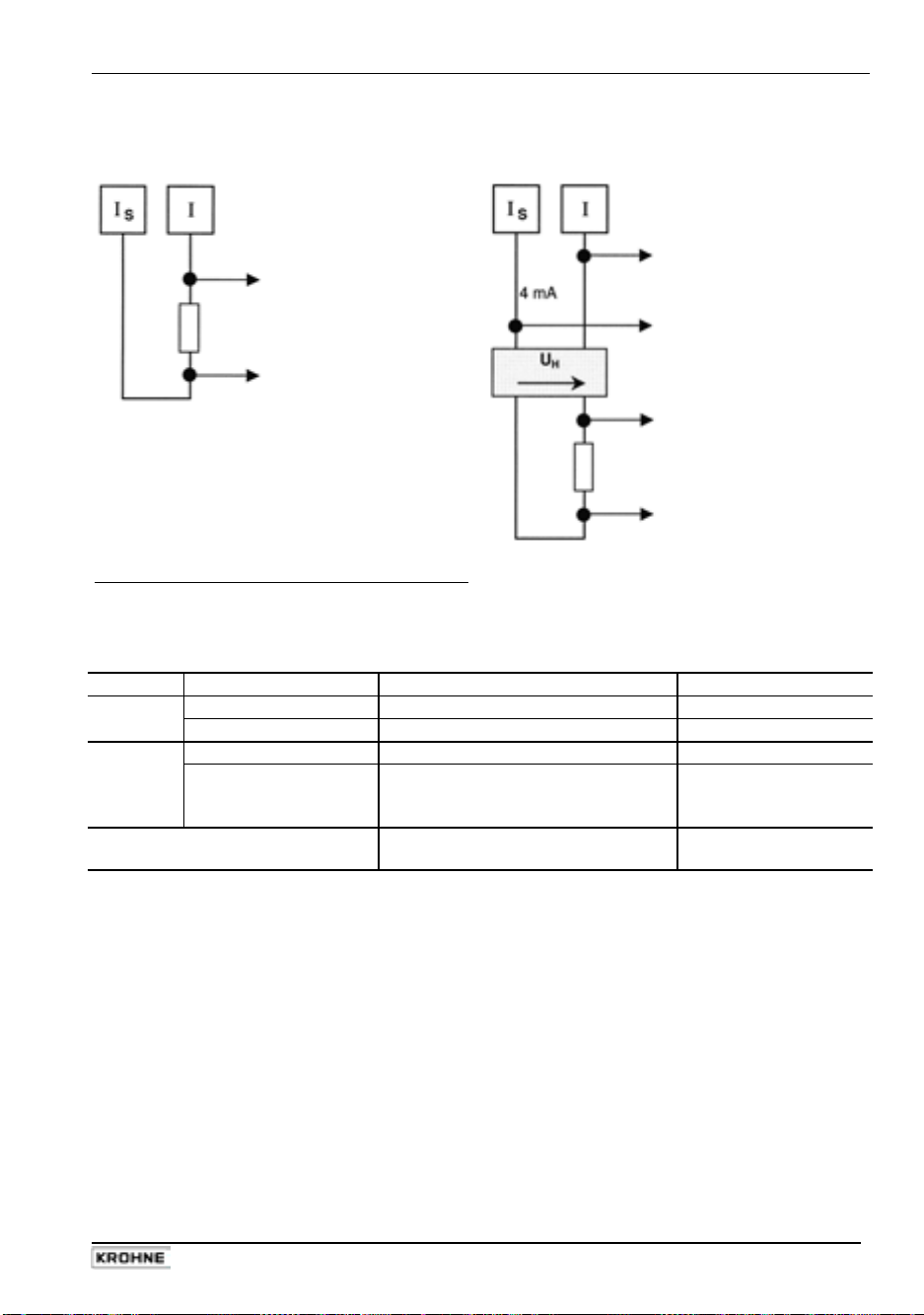
Part C Special applications, functional checks, service, and order numbers Sect. 6.4
Electrical connection
HART® - active
not with multidrop operation
HART® - passive
only with multidrop operation
Bürde ≥ 230 Ω
active
to HART
or smart-converter
®
- communicator
passive
to next
®
- device
HART
power supply unit
to HART
or Smart- converter
®
- communicator
Power supply unit (and section switch amplifier)
must be set up accordingly if in use for HART®
operation. For setting active/passive operation see Sect. 6.8.
Settings and operation
Fct. Parameter Point-to-point mode Multidrop mode
1.05 Function 1 CORRECT. or 2 CORRECT.
3.09 Communication
Range I
Address
4-20 mA or I
≥ 4 mA I0% ≥ 4 mA
0%
HART HART
0 01, 02, 03 ..... 15
OFF
(use one address at
one time only)
Operation
Current output
active or passive
passive only
For further information on setting the signal converter refer to chapters 4 and 5.
®
HART
operating tools / Device Description (DD)
The signal converter can be operated either via its local operator interface or by means of the
®
communicator, which is available from KROHNE.
HART
Operator control by means of the HART® communicator requires a device description (DD) which
we can load for you into the communicator. We can, of course, also load the DDs of all
manufacturers who have filed their DDs with the HART
®
Communication Foundation.
If you wish to use the signal converter in your operating tool, for example, please ask for the
description of the HART
functionality via HART
®
command used so that you can address the complete signal converter
®
.
IFC 110 F 59
05/2003
Page 60

Sect. 6.4 Part C Special applications, functional checks, service, and order numbers
6.4.3 KROHNE RS 485 Interface (Option)
Electrical connection
RS 485 Interface (Option, connection at plug-in terminal RS)
The shields can be grounded as follows:
*
1) directly at both ends
or where there is risk of circulating currents,
2) directly at one end (static shielding) or
3) directly at one end and capacitive at the other end.
In the case of 2) and 3), a decrease in EMC is to be expected.
It is essential to blank off the final signal converter's electrical bus. To do this, solder up the
semicircular circuits of solder points S3 and S4 on the RS485 - PCB. For further information refer
to section 8.7.
The RS 485 protocol is available. Please contact your local KROHNE supplier / company.
Settings for use in interface operation
Fct. Parameter KROHNE RS 485 Interface
3.09
Communication KROHNE
Address 000-239
Baud rate
• 1200 • 9600
• 2400 • 19200
• 4800
For further information on setting the signal converter refer to chapters 4 and 5.
60 IFC 110 F
05/2003
Page 61

Part C Special applications, functional checks, service, and order numbers Sect. 6.5
6.5 Pulsating flow
Application
Downstream of positive displacement pumps (reciprocating or diaphragm pumps) without
pulsation damper.
Resetting the signal converter, see Sections 4 and 5.
Changing the settings
• Fct. 3.02 FIELD FREQ.
– Stroke frequency less than 80 strokes/min. (at max. pump lift), do not change setting.
– Stroke frequency 80-200 strokes/min. (at max. pump lift), change setting to 1/2,
only recommended for PROFIFLUX 5000 F (DN 2.5-100 and 1/10”-4”)
and ALTOFLUX 4000 F (DN 10, 15, 50-100 and
for other types and sizes please consult factory.
– Please note: at stroke frequencies near the limit of 80 strokes/min. additional measurement
deviations of ± 0.5 % of the measuring value may occur occasionally.
• Fct. 3.06 APPLICAT.
Change setting of subfunction ”FLOW” to ”PULSATING”.
• Fct. 1.04 DISP. FLOW
Change setting to ”BARGRAPH” in order to be able to evaluate the display ripple.
• Fct. 1.02 TIMECONST. (change time constant)
– Change setting to ”ALL” and set time (t) to seconds.
1000
– Recommendation: t [s] =
– Example: min. number of strokes during operation = 50 strokes/min.
1000
With this setting, the residual ripple of the display is approx. ± 2 % of the
(change the magnetic field frequency)
1
/10”, 1/2”, 2”-4”),
(adapt modulation limit of A/D converter to the application)
(change display of flow)
min. number of strokes/min.
t [s] =
50/min.
= 20 s
measuring value. Doubling the time constant reduces the residual ripple of
the display by a factor of 2.
IFC 110 F 61
05/2003
Page 62

Sect. 6.6 Part C Special applications, functional checks, service, and order numbers
6.6 Unstable display and outputs
Unstable displays and outputs may occur:
– with high amounts of solids,
– with inhomogeneities,
– with badly blended mixtures,
– after constant chemical reactions in the process liquid or
– in ALTOFLUX 4000 F flow sensors when the wrong electrode material is selected for the
process liquid, e.g. Hastelloy B2 for hydrochloric acid.
If the flow is pulsating because of the use of diaphragm or reciprocating pumps please refer to
Section 6.5.
Resetting the signal converter, see Sections 4 and 5.
When changing the signal converter settings, the green LED (normal) and the red LED (error)
on the front panel of the signal converter start to flash rapidly and frequently. This indicates that
the A/D converter range is frequently exceeded and that not all measured values are evaluated.
Change the following settings to allow the display ripple to be properly evaluated:
Select ”BARGRAPH” in Fct. 1.04 DISPLAY, subfunction ”DISP. FLOW” and select ”YES” in
submenu ”DISP. MSG.”.
Press ↵ key 4 times to return to measuring mode.
The following displays are possible in measuring mode:
= A/D converter range exceeded
ADC
and
OVERFL. I, P
PLEASE NOTE:
After each of the following changes check if the display and outputs are unsteady in measuring
mode. Do not proceed to the next step unless the display and outputs continue to be unsteady.
• Fct. 1.02 TIMECONST.
– Set to ”ONLY I”; set to ”ALL” when pulse output is also unsteady.
– Set time constant to approx. ”20 seconds”, check if display remains unsteady and correct if
necessary.
• Fct. 3.06 APPLICAT.
Change setting of subfunction ”FLOW” to ”PULSATING” on a trial basis.
When the green LED and red LED continue to flash,
change the setting of subfunction ”ADC GAIN” to 30.
Should the green LED and red LED continue to flash frequently, set value to 10.
• Fct. 3.02 FIELD FREQ.
Change the setting to 1/2 on a trial basis.
If this has no significant effect, restore the last setting (usually 1/6).
Only recommended for PROFIFLUX 5000 F (DN 2.5-100 and 1/10-4 inch)
and ALTOFLUX 4000 F (DN 10, 15, 50-100 and
for other types and sizes please consult factory.
If display and outputs continue to be unsteady or if the set time constant proves too high for your
and/or P2 = one or several output ranges exceeded
Change procedure A
(change time constant)
(adapt modulation limit of A/D converter to the application)
(change magnetic field frequency)
1
/10, 1/2, 2-4 inch),
specific application (Fct. 1.02) please proceed as described in change procedure B.
62 IFC 110 F
05/2003
Page 63

Part C Special applications, functional checks, service, and order numbers Sect. 6.6
Change procedure B
PLEASE NOTE:
Do not proceed according to change procedure B unless the steps of change procedure A
proved unsuccessful.
Change procedure B must not be adopted for pulsating flows downstream of positive
displacement pumps.
The following settings result in a modified dynamic behaviour of the system which is no longer
defined by the setting of the time constant in Fct. 1.02.
• Fct. 1.02 TIMECONST.
Change setting to 3 seconds.
• Fct. 3.06 APPLICAT.
– Select ”YES” in subfunction ”SPEC. FILT.” to activate a special noise filter.
– Subfunction ”LIMIT VAL.” defines a window with a width (somewhere around the mean
flow) equivalent to the value in PERCENT of the full-scale range Q
(Fct. 3.02, subfunction ”FULL SCALE”).
set here
100%
This value must always be a lot smaller than the amplitude of the display ripple
(peak-to-peak).
Example:
ripple mean value ± 25 m³/h = ± 5% of full-scale range Q
set amplitude to e.g. ± 2%
Signals outside the ± LIMIT VALUE window are cut off (clipping). When e.g. interferences
full-scale range Q
500 m³/h
100%
100%
cause the measuring value to leave this window for a short time, the rate of change of the
display and outputs is limited to...
∆Q
max
∆T
%
s
=
LIMIT VAL. Formula applying to
TIMECONST. (Fct. 1.02) the above example
∆Q
∆T
max
2% %
=
= 0.66
3 s
s
The delay required for passing on major changes of flow to the display and outputs is defined in
subfunction ”LIMIT CNT.”.
Set subfunction ”LIMIT CNT.” to 10 on a trial basis.
Should the measuring value leave the above window in one direction more than 10 times, this
window is temporarily rendered inactive.
Display and outputs follow major changes of flow with the appropriate speed.
This setting provides an additional dead time for display and outputs:
Dead time = LIMIT CNT. x duration of measuring cycle
Duration of measuring cycle = approx. 60 ms (for magnetic field frequency = 1/6 ´ line frequency,
see Section 3.02, subfunction ”FIELD FREQ.”).
A ”10” set in subfunction ”LIMIT CNT.” results in a dead time of approx. 600 milliseconds.
By changing the subfunctions ”LIMIT VAL.”, ”LIMIT CNT.” and ”TIMECONST.”
(Fct. 1.02) on a trial basis, a setting can normally be found which ensures
that the display and outputs are sufficiently stable.
Each of the steps described above must be followed by a check
of the ripple of display and outputs in measuring mode.
IFC 110 F 63
05/2003
Page 64

Sect. 6.8 Part C Special applications, functional checks, service, and order numbers
6.7 Quickly changing flows
Application
For filling processes, high-speed control circuits, etc.
Resetting the signal converter, see Sections 4 and 5.
Changing the settings
• Fct. 1.02 TIMECONST.
(change the time constant)
– Change the setting to ”ONLY I” and set time to 0.2 seconds.
• Dynamic behaviour for sizes DN 2.5-300 and 1/10 -12 inch
Dead time: approx. 0.06 at 50 Hz line frequency
approx. 0.05 at 60 Hz line frequency
Time constant: as set above, current output (mA) then is 0.1 seconds
• Reduction of dead time by factor 3
(possible by changing the magnetic field frequency)
Change Fct. 3.02 FLOW METER, subfunction ”FIELD FREQ.” to ”1/2”,
only recommended for PROFIFLUX 5000 F (DN 2.5-100 and 1/10 -4 inch)
and ALTOFLUX 4000 F (DN 10, 15, 50-100 and
1
/10, 1/2, 2-4 inch),
for other types and sizes please consult factory.
6.8 Changeover of current output, active / passive mode
Standard factory setting: active mode
The current output can be changed over to the passive mode. This requires a power source,
either an external one or via the isolated internal one (24 V DC), power terminals E+ / E-.
See Sect. 2.6 for connection diagrams.
Proceed as follows to change over from active to passive mode, or vice versa.
Changes on the I/O circuit board (inputs/outputs), see diagram in Sect. 8.7
Switch off power source before opening the housing!
1)
Remove glass cover from control compartment (detach 4 screws).
2)
Remove cover from terminal compartment (detach 2 screws).
3)
In terminal compartment, pull off all plug-in terminals.
4) Detach 4 screws from the front panel F and carefully pull complete electronic unit out of the
converter housing using the grip at the top of the front panel.
5) Place electronic unit down on front panel F.
6) Detach the two fastening screws SLP from the I/O board (inputs/outputs) and carefully pull
the board out of the pin base, see figures in Sect. 8.7.
7) On the printed side of the I/O board, transpose the two jumpers X3 and X6, in the same
direction, to Position A (= active mode) or Position P (= passive mode).
8)
Reassemble in reverse order, Points 6) - 1).
9) Please note:
In the passive mode, load impedance monitoring under Fct. 1.04 DISPLAY and
DISP. MESSAGES - yes is not possible.
64 IFC 110 F
05/2003
Page 65

Part C Special applications, functional checks, service, and order numbers Sect. 6.9
6.9 Empty pipe detection EPD
The signal converter is equipped as standard with an EPD (Empty Pipe Detection)
which only needs to be activated as and when required.
To ensure proper functioning, the following requirements need to be met:
Type
of signal cable
A = Type DS
B = Type BTS
Settings for empty pipe detection (EPD)
• Fct. 3.06 APPLICATION • EMPTY PIPE • YES (switched on) • NO (switched off)
The calibration mode must be run through during initial start-up!
• If“YES“ selected, the impedances for EMPTY and FULL PIPE need to be determined.
• Select subfunction VALUE FULL and CALIB. YES (determine impedance for “full pipe“)
WAIT (approx. 20 s)
• Select subfunction VALUE EMPTY and CALIB. YES (determine impedance for “empty pipe“)
WAIT (approx. 20 s)
• Store values after completion of calibration for “Full” and “Empty” values; quit operator control
after the second calibration.
When the electrodes are not wetted (= empty pipe), typically a response time of approx. 20
seconds is required before “empty pipe“ is indicated. In this time undefined display values and
output signals are possible.
Functional description
A high-resistance AC voltage is applied
to the electrodes. The process liquid in
the measuring tube forms a voltage
divider together with the internal
resistance of the circuit. The voltage
ratio is measured and weighted (see
figure on right). Impedance and length
of electrode cable will also affect the
result.
The result is a numerical value
proportional to the impedance at the
input. The switching point of the Empty
Pipe Detector is defined when the
system is calibrated for “full pipe“ and
“empty pipe“(at approx. 2/3 of the range
between the two calibration points). In
order to function properly there must be
a difference of at least “10“ between the
two calibration points. In operation, the
display indicates in the range between
0 and 150 (non-dimensional). The value
for “FULL PIPE“ must be lower than that
for “EMPTY PIPE“.
Electrical conductivity
of process liquid
> 200 µS/cm
> 50 µS/cm
Nominal size
of flow sensor
≥ DN 25 / ≥ 1“
≥ DN 25 / ≥ 1“
Process
liquid
Display
FULL
PIPE
Switching point
Impedance
Max. length
of signal cable
< 20 m / 65 ft
< 20 m / 65 ft
EMPTY
PIPE
IFC 110 F 65
05/2003
Page 66

Sect. 6.10 Part C Special applications, functional checks, service, and order numbers
6.10 Stable signal outputs with empty measuring tube
Output signals can be stabilized to values as for ”zero” flow to prevent undefined output signals
when the measuring tube is empty.
– Display 0
– Current output 0 or 4 mA, see setting in Fct. 1.05
– Pulse output P no pulses (= 0 Hz), see setting in Fct. 1.06
– 2nd pulse output A1 no pulses (= 0 Hz), see setting in Fct. 1.07
Prerequisite:
LA / S2 Empty Tube stabilization LA / S4 electrode cleaning
steady display at “0“ flow
LA / S2 should be used when problems are
encountered with EPD or the limits of the
application are exceeded.
At “0“ flow, the electrodes are connected to 0 V
(chassis) via high-resistance resistors.
Important, please note!
• Observe the directions and regulations and the electrical data specified in the
EC type test certificate.
• In addition to the regulations for heavy-current installations (VDE 0100),
pay particular attention to the requirements specified in EN 60079-14 “Electrical
equipment in hazardous areas”.
• Assembly, installation, commissioning and maintenance work may only be carried
out by “personnel trained in explosion protection”!
• electrical conductivity of process liquid ≥ 200 mS/cm,
≥ 500 mS/cm for sizes DN 2.5 - 15 and
1
/10” - 1/2”.
• Signal cable length ≤ 20 / ≤ 65 ft and vibration free with signal
converter.
and Empty Tube stabilization
LA / S4 prevents any deposits of highresistance layers on the electrodes (e.g. fat
from very creamy milk) and effects stabilization
similar to the LA / S2.
For this purpose, the electrodes are connected
to –12 V via high-resistance resistors.
0 V
- 12 V
- 12 V
To join the “semicircles“ of the three soldering
points S1, S2 and S4, see under ”Point 8“.
Possibly reset low-flow cutoff (SMU),
see under Point 11
To join the “semicircles“ of the three soldering
points S1, S3 and S4, see under ”Point 8“.
Possibly reset low-flow cutoff (SMU),
see under Point 11
Please note!
Only use the two functions, if Empty Pipe Detection (EPD) is switched off, see Sect. 6.9 and in
Fct. 3.06 Application → EMPTY PIPE.
66 IFC 110 F
05/2003
Page 67

Part C Special applications, functional checks, service, and order numbers Sect. 6.10
Changes on A/D converter PCB, see illustration in Section 8.7
Switch off the power supply before opening the housing !
1)
Remove the glass cover from the control compartment (remove 4 screws).
2)
Remove the cover from the terminal compartment (remove 2 screws).
3)
Pull all plug-in terminals out of the sockets inside the terminal compartment.
4)
Remove 4 screws from the front panel, take hold of the handle on the upper end of the front
panel and carefully pull the complete electronic unit out of the signal converter housing.
5) Put down the electronic unit with the front panel F facing down.
6) Unscrew the two S
screws from the printed circuit boards FSV (field current supply) and
LP
ADC (analog/digital converter) and carefully pull both PCBs out of their plug bases (see
illustration in Section 8.7).
7)
Loosen the common plug-and-socket connection.
8) The circuit side of the ADC circuit board has 4 soldering points S1-S4
(two semicircles, each - see illustration in Section 8.7).
Carefully scratch the protective lacquer off the soldering points which are used. Do not
remove the protective lacquer from soldering point S3. Do not damage the conductive tracks.
9)
Connect the semicircles of soldering points which are used with tin solder.
10)
Re-assemble in reverse order (items 7 to 2).
11)
For LA / S2 (empty tube stabilization) and LA / S4 (electrode cleaning and empty tube
stabilization), check the setting of the low-flow cutoff SMU, Fct. 1.03, and reset if necessary:
L.F.Cutoff switched on, range:
Full scale range Q
Cutoff ...... values
100%
... OFF ... ... ON ...
> 3 m/s > 10 ft/s > 2 % 1 %
1 – 3 m/s 3 -10 ft/s > 6 % 4 %
< 1 m/s < 3 ft/s > 10 % 8 %
IFC 110 F 67
05/2003
Page 68

Sect. 7.1 Part C Special applications, functional checks, service, and order numbers
7 Functional checks
7.1 Checking the zero with IFC 110 F signal converter, Fct. 3.03
• Set ”zero” flow in the pipeline. Make sure that the measuring tube is completely filled with
liquid.
• Switch on the system and wait 15 minutes.
• Press the following keys for zero measurement:
Key Display Description
→
Fct. 1.00 OPERATION
2x ↑
→
2x ↑
→
↑
↵
subfunction ”DISP. FLOW”.
Zero is measured, duration approx. 15-90 s. ”WARNING” is
STORE NO
4 times = return to measuring mode
↑
↵
(2x) 3x ↵
If ”YES” is selected in Fct. 3.04 ENTRY CODE,
key in 9-stroke CODE 1 now: → → → ↵ ↵ ↵ ↑ ↑ ↑
Fct. 3.00 INSTALL.
Fct. 3.01 LANGUAGE
Fct. 3.03 ZERO SET
CALIB. NO
CALIB. YES
0.00 - - - - - / - - - Flow rate displayed in set unit, see Fct. 1.04 DISPLAY,
displayed when flow is ”>0”, acknowledge by pressing ↵ key.
If new value is not to be stored, press ↵ key (3 times)
STORE YES
Fct. 3.03 ZERO SET Store new zero value
- - - - - - - - - - - - / - - - Measuring mode with new zero
7.2 Checking the measuring range Q, Fct. 2.01
• For this test a measuring value can be simulated in the range of -110 to +110 percent of Q
(set full-scale range, see Fct. 1.01 FULL SCALE).
• Switch on the system.
• Press the following keys for checking the measuring range:
Key Display Description
→
Fct. 1.00 OPERATION
↑
→
→
↑
↵
± 10 PCT.
↑
± 100 PCT.
± 110 PCT.
↵
(2x) 3x ↵
If ”YES” is selected in Fct. 3.04 ENTRY CODE,
key in 9-stroke CODE 1 now: → → → ↵ ↵ ↵ ↑ ↑ ↑
Fct. 2.00 TEST
Fct. 2.01 TEST Q
SURE NO
SURE YES
0 PCT. Current, pulse and status outputs indicate corresponding values.
± 50 PCT.
Fct. 2.01 TEST Q End of test, actual measured values again available at outputs
- - - - - - - - - - - - / - - - Measuring mode
Select with ↑ key
100%
68 IFC 110 F
05/2003
Page 69

Part C Special applications, functional checks, service, and order numbers Sect. 7.3
7.3 Hardware information and error status, Fct. 2.02
• Before consulting the factory about errors or flow measurement problems, please invoke
Fct. 2.02 HARDW. INFO (hardware information).
• An 8-character and a 10-character status code are stored under this function in each of
3 ”windows”. These 6 status codes allow your compact flowmeter to be subjected to a simple
and rapid diagnosis.
• Switch on the system.
• Press the following keys for a display of the status codes:
Key Display Description
→
Fct. 1.00 OPERATION
↑
→
↑
→ → MODUL ADC
- - - - - - - - - Example for status code
↵ → MODUL I/O
- - - - - - - - -
↵ → MODUL DISP.
- - - - - - - - -
↵
(2x) 3x ↵
If ”YES” is selected in Fct. 3.04 ENTRY CODE,
key in 9-stroke CODE 1 now: → → → ↵ ↵ ↵ ↑ ↑ ↑
Fct. 2.00 TEST
Fct. 2.01 TEST Q
Fct. 2.02 HARDW. INFO
-.- - - - -.- -
-.- - - - -.- -
-.- - - - -.- -
PLEASE NOTE DOWN ALL 6 STATUS CODES !
Fct. 2.02 HARDW. INFO Terminate hardware information
- - - - - - - - - - - - - / - - - Measuring mode
1st window
2nd window 3.25105.02
3rd window
3A47F01DB1
( 8-character code, 1st line)
(10-character code, 2nd line)
7.4 Hardware test, Fct. 2.03
Please note:
Before beginning the test, deactivate any alarms and controllers as the current output will be
tested with three values 4, 4.7 and 23 mA for a short period.
Key Display Description
→
Fct. 1.00 OPERATION
↑
→
2 x ↑
→
↑
↵
- - - - - - - - 1st error List of errors see Sect. 4.5. Errors are
↑
↑
↵
(2x) 3x ↵
If you need to return your flowmeter to KROHNE, please refer to the last-but-one page of
If ”YES” is selected in Fct. 3.04 ENTRY CODE,
key in 9-stroke CODE 1 now: → → → ↑ ↑ ↑ ↵ ↵ ↵
Fct. 2.00 TEST
Fct. 2.01 TEST Q
Fct. 2.03 HARDW. TEST Hardware test
SURE NO
SURE YES
WAIT Hardware test in progress, duration approx. 60 seconds
- - - - - - - - 2nd error always displayed independent of setting in
- - - - - - - - 3rd error
Fct. 2.03 HARDW. TEST Terminate hardware test
- - - - - - - - - - - - - / - - - Measuring mode
}
Fct. 1.04. If no error is detected, refer to next line.
these instructions.
IFC 110 F 69
05/2003
Page 70

Sect. 7.5 Part C Special applications, functional checks, service, and order numbers
7.5 Faults and symptoms during start-up and flow measurement
• Most faults and symptoms occurring with the flowmeters can be eliminated by following the
instructions indicated in the following tables.
• For greater clarity, faults and symptoms in the tables are divided into different groups.
• LED
Group LED Display Cause Remedial action
LED 1
LED 2
LED 3
LED 4
light-emitting diodes on the front panel (status messages)
D
display
I
current output I
P
pulse outputs P and A1
S
status outputs D1, D2, A1 and A2
C
control inputs C1 and C2
Before contacting the KROHNE Service Department,
please read the instructions in the table. THANK YOU.
Both LEDs flash A/D converter range Reduce flow rate;
exceeded if unsuccessful, test as
described in Section 7.6
Measuring tube drained,- Fill measuring tube
A/D conv. range exceeded
Red LED flashes Fatal error, hardware and/or Replace signal converter,
software fault see Section 8.3
Cyclic flashing of red Hardware fault, watchdog Replace signal converter,
LED, approx. 1 sec. trips see Section 8.3
Red LED on Hardware fault Replace signal converter,
continuously see Section 8.3
70 IFC 110 F
05/2003
Page 71

Part C Special applications, functional checks, service, and order numbers Sect. 7.5
Group D Display Cause Remedial action
D 1
D 2
D 3
D 4
D 5
D 6
D 7
D 8
D 9
D 10
D 11
D 12
D 13
D 14
D 15
LINE INT. Power failure Delete error message in
Note:
power failure reset totalizer if necessary.
OVERFL. I Current output range Check instrument parameters
exceeded and correct if necessary. Error
message is deleted automati cally after cause has been
eliminated.
OVERFL. P Pulse output range Check instrument parameters
exceeded and correct if necessary. Reset
Note:
totalizer deviation is ted automatically after cause
possible has been eliminated.
ADW A/D converter range Error message is deleted
exceeded automatically after cause
has been eliminated.
FATAL.ERROR Fatal Error, all outputs are Replace signal converter,
set to ”min” values see Sect. 8.3 or consult KROHNE
Service, having first noted down
hardware information and error
status, see Sect. 7.3, Fct. 2.02.
TOTALIZER Counts lost Delete error message in
(overflow, data error) RESET/QUIT. menu.
I SHORT Short circuit at current Check electrical connection
output acc. to Sect. 2.2 and correct if
necessary.
I OPEN Open current output
ADC PARAM. Fault detected on the Check measuring accuracy.
ADC HARDW. ADC printed circuit Replace ADC printed circuit
ADC GAIN
STARTUP, Hardware fault, Replace signal converter
cyclic flashing watchdog trips (see Sect. 8.3) or consult
KROHNE Service, having first
noted down hardware
information and error status,
see Sect. 7.3, Fct. 2.02.
BUSY Displays for flow, totalizers Change setting in Fct. 1.4
and messages disabled
Unsteady display Low electrical conductivity, Increase time constant in
high solids content, Fct. 1.2, refer to Sect. 6.5 and 6.7.
pulsating flow
No display Power supply OFF Switch on power supply.
Check power supply fuse F5 Replace if blown,
(F6 for DC versions)
in terminal compartment
no counting during RESET/QUIT. menu,
totalizer. Error message is dele-
Load ≥ 15 Ω !
Provide load ≤ 500 Ω !
board (see Sect. 8.4) or consult KROHNE Service, having
first noted down hardware
information and error status,
see Sect.. 7.3, Fct. 2.02
IFC 110 F 71
05/2003
Page 72

Sect. 7.5 Part C Special applications, functional checks, service, and order numbers
Group I Faults / Symptoms Cause Remedial action
I 1
Invoke test function 2.03
for analysis see Sect.7.4. Display shows...
I 2
Wrong flow direction setting Set properly in Fct. 3.1.
Current output switched off Switch on in Fct. 1.5.
Receiver instrument
indicates ”0”
(this check is only usefully, I SHORT
if current output is operating in Current output shorted,
active mode, see Sect. 6.8!)
I OPEN
Receiver instrument Wrong connection/polarity Connect properly,
indicates “0“. see Sect. 2.2 and 2.6.
Eliminate short circuit,
Load must be ≥ 15 Ω !
Load is < 15 Ω
Find interruption and eliminate.
Load resistance > 500 Ω
No information displayed
after test
as described for faults
Circuit and/or receiver
instruments defective
active mode
Receiver instruments and/or
exernal voltage source
defective
Internal power supply (E+E-)
is voltage source, shorted or
defective current output
passive mode
Defective current output Replace I/O PCB (see Sect. 8.4)
and
I 2
Check circuit and receiver
instrument at
if necessary. Check position of
jumper X3 + X6 for active mode,
see Sect. 6.8 and check fuse F9
on I/O PCB and replace if
necessary, see Sect. 8.4
and 8.7.
Check connections, receiver
instruments and external voltage
source and replace if necessary.
Check connections and cables,
see Sect. 2.3 and 2.6.
Voltage between E+and Eapprox. 24 V. If voltage is a lot
smaller, switch off the instrument, eliminate the short circuit,
check position of jumper
X3 + X6 for passive mode,
(see Sect. 6.8) and replace
fuses F1 and F8 on the I/O PCB
if necessary. Switch the
instrument back on. If it still
does not operate, current output
is defective. Replace I/O PCB or
complete electronic unit,
see Sect. 8.3 and/or 8.4.
or consult KROHNE Service,
having first noted down hardware information and error
status, see Sect. 7.3, Fct. 2.02.
I 9
and replace
/ I
I
S
72 IFC 110 F
05/2003
Page 73

Part C Special applications, functional checks, service, and order numbers Sect. 7.5
Group I Faults / Symptoms Cause Remedial action
I 3
I 4
I 5
I 6
I 7
I 8
I 9
22 mA are available at Range of current output I is Check instrument parameters
current output (fault current) exceeded and correct if necessary
(see Sect. 2.2 and 5.7) or con sult KROHNE Service, having
first noted down hardware
information and error status,
see Sect. 7.3, Fct. 2.02.
22 mA are available at Fatal Error Replace signal converter or
current output (fault current) consult KROHNE Service,
and red LED flashes having first noted down hard ware information and error
status, see Sect. 7.3, Fct. 2.02
Unsteady display Electric conductivity of Increase time constant
process liquid too low (see Sect. 5.2, Fct. 1.2).
Also refer to Sect. 6.7.
Receiver instruments Control input C1 or C2 is Change setting (see Sect. 5.10,
indicate ”constant value” set to ”Hold outputs” and Fct. 1.11 and 1.12), or
is activated deactivate control input.
Jumping current values Current output is set to Change hysteresis or tripping
automatic range change ranges, see Sect. 5.20.
F/R-Mode: Different ranges set for Change setting,
different displays for identical ”forward flow” and see Sect. 5.15, Fct. 1.05
flow volumes in both ”reverse flow” ”Rev. range”.
directions
Receiver instruments Control input C1 or C2 is set Change setting (see
indicate ”min. values” to ”Zero outputs” or ”Hold Sect. 5.10, Fct. 1.11 and 1.12)
outputs” and is activated or deactivate control input.
IFC 110 F 73
05/2003
Page 74
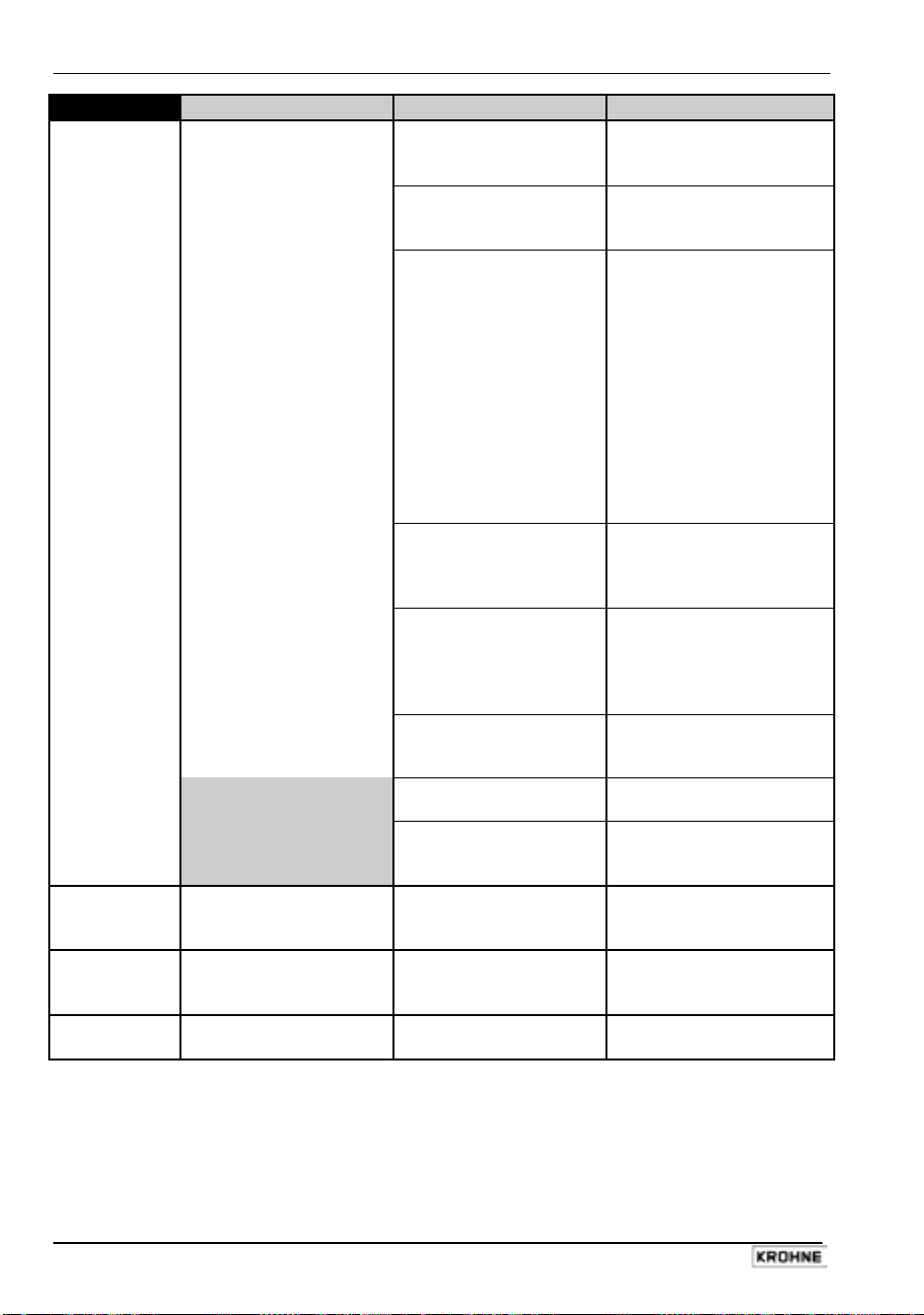
Sect. 7.5 Part C Special applications, functional checks, service, and order numbers
Group P Faults / Symptoms Cause Remedial action
P 1
P 2
P 3
P 4
Totalizer connected Wrong connection/polarity Connect properly, see
but does not count pulses Sect. 2.3 and 2.6, note
recommended resistances !
Totalizer or exernal voltage Check connections, totalizer
source defective and external voltage source
and replace if necessary.
Internal power supply (E+E-) Check connections and cables,
is voltage source, shorted or see Sect. 2.3 and 2.6.
defective pulse output Voltage between E+and E approx. 24 V. If voltage is a lot
smaller, switch off the instru ment, eliminate the short circuit
and replace fuses F1 and F8 on
the I/O PCB if necessary. Switch
the instrument back on. If it still
does not operate, pulse output
is defective. Replace I/O PCB or
complete electronic unit,
see Sect. 8.3 and/or 8.4.
Pulse output switched off or Switch on pulse output and
wrong flow direction setting change flow, see Sect. 5.8 and
5.13, Fct. 1.06 (P), 1.07 (A1)
and 3.02.
Fatal Error, red LED is on Replace signal converter or
consult KROHNE Service,
having first noted down
hardware information and error
status, see Sect. 7.3, Fct. 2.02.
Control input C1 or C2 is set Change settings, see
to ”Zero outputs” and is Sect. 5.10, Fct. 1.11 and 1.12
activated or deactivate control input.
Terminals A1 and A^ are not Switch on in Fct. 3.07 and set
These causes only apply
to the 2nd pulse output P2,
terminal A1 !
Constant output of Control input C1 or C2 is set Change setting, see
totalizer pulses to ”Hold outputs” and is Sect. 5.10, Fct. 1.11 and 1.12
activated or deactivate control input.
Unsteady pulse rate Electrical conductivity of Increase time constant
process liquid is too low (see Sect. 6.5-6.8) or
consult KROHNE Service.
Pulse rate too high or too low Incorrect pulse output settings Correct settings in
Fct. 1.06 (P) or 1.07 (A1).
defined as a 2nd pulse output in Fct. 1.07.
Resistance of totalizer too low Re-position jumper X4 on
for DC operation, I > 100 mA I/O PCB to suit DC operation,
see Sect. 6.3.
74 IFC 110 F
05/2003
Page 75
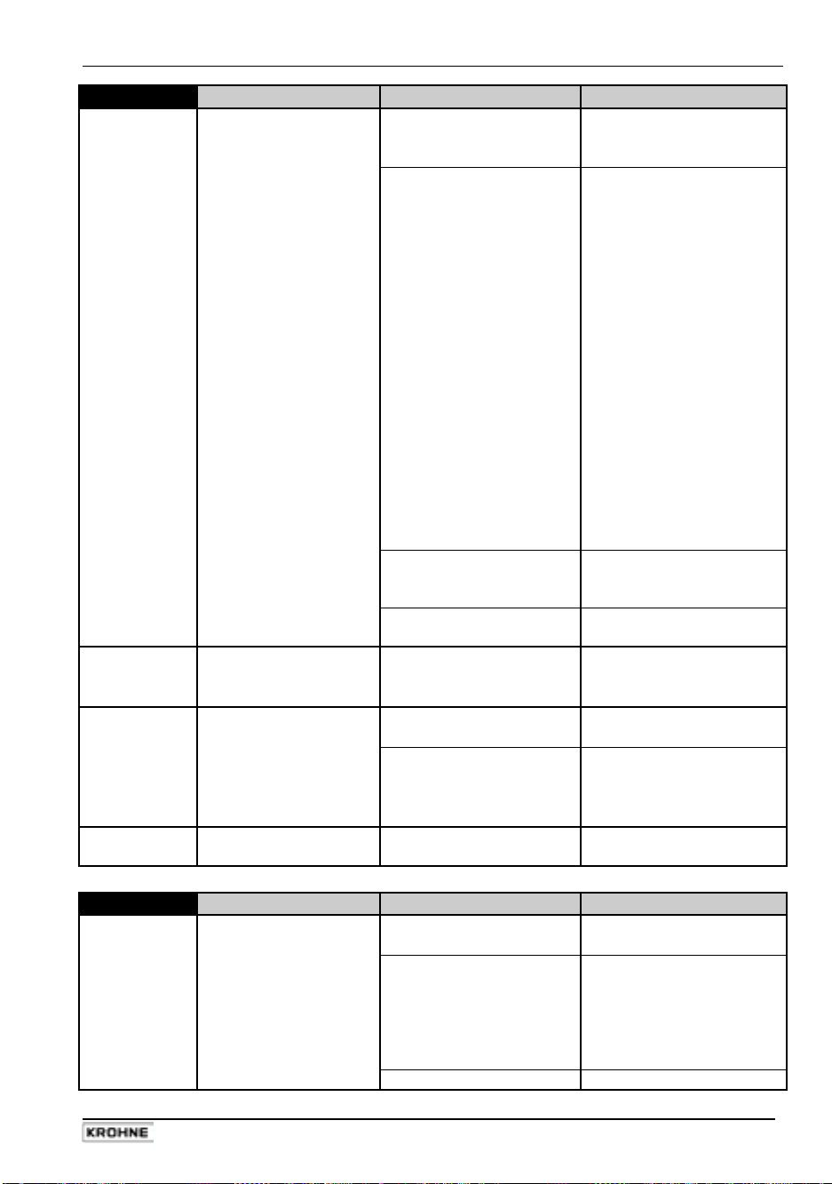
Part C Special applications, functional checks, service, and order numbers Sect. 7.5
Group S Faults / Symptoms Cause Remedial action
S 1
(A1, A2, D1, D2)
S 2
(A1, A2, D1, D2)
S 3
(only for A1)
S 4
(only for A1)
No reaction from connected Defective signalling Check signalling instrument(s)
signalling instrument(s) instrument(s) or external or external voltage source and
voltage source replace if necessary.
Internal power supply (E+/E-) Check connections and cables,
is voltage source: shorted, one change if necessary
or several pulse outputs (see Sect. 2.6).
defective Voltage between E+ and E approx. 24 V.
Check fuse F8 on the I/O PCB
and replace if necessary
(see Sect. 8.7). If instrument
still does not operate, check
status outputs and replace if
necessary:
If it still does not operate, one
or several pulse outputs are
defective.
Replace I/O PCB, see Sect. 8.4.
Control inputs C1 and C2 Change setting, see
are set to ”Hold outputs” or Sect. 4.4 and 5.10,
to ”0” Fct. 1.11 and 1.12
In addition to this, the red Replace signal converter,
LED flashes = Fatal Error see Sect. 8.3.
Signalling instrument(s) ”All Error” or ”Fatal Error” Check settings in Fct. 1.07-1.10
is(are) constantly tripped settings and change if necessary,
see Sect. 4.4 and 5.9.
No reaction of connected Terminal ”A1” not defined as Adjust in Fct. 3.07.
signalling instrument status output
Wrong connection/polarity Observe polarity for driver
see Sect. 6.3.
Cyclic tripping of Terminal ”A1” not defined as Adjust in Fct. 3.07.
signalling instrument status output
fuses F.. on the I/O PCB for the
for terminals A1 and A⊥
F2
for terminals A2 and A⊥
F3
for terminals D1 and D⊥
F4
for terminals D2 and D⊥.
F5
capacity
= ”+” and
A1
0.1 < I ≤ 0.2 A
⊥ = ”–”
A
Group C Faults / Symptoms Cause Remedial action
C 1
No function of control inputs Wrong connection Connect properly,
see Sect. 2.5 and 2.6.
Defective control input C or Check connections and cables
voltage source (internal or and change or replace if
external) necessary. Check voltage
source. Check fuses F6 and F7
on I/O PCB and replace if
necessary.
Wrong setting of control inputs Change, see Sect. 4.4 and 5.10.
IFC 110 F 75
05/2003
Page 76

Sect. 7.6 Part C Special applications, functional checks, service, and order numbers
7.6 Checking the flow sensor
Always switch off the power supply before opening the housing.
Required measuring instruments and tools
• Ohmmeter with at least 6 V measuring voltage range
• or AC voltage/resistance bridge
• Note:
accurate measurements in the electrode area can only be obtained with
an AC voltage/resistance bridge. The measured resistance also heavily
depends on the electrical conductivity of the process liquid.
Preparations
• Switch off the power supply.
• Remove the cover from the terminal compartment (remove 2 screws).
• Pull out the two plug-in terminals SC (5-pin, signal line) and FP (4-pin, field current supply
line), see illustration in Section 8.1.
• Fill the measuring tube of the flowmeter completely with process liquid.
• Please note:
the following measurements must only be carried out for plug-in terminals
which are occupied (used).
Action
Resistance measurements at
plug-in terminals SC (5-pin, signal line)
and FP (4-pin, field current supply line)
1
Measure resistance between wires
and 8
7
If higher,
wire break.
2
Measure resistance between wires
and 7 or between wires 1 and 8
1
3
Measure resistance between wires
and 2 and between 1 and 3 (see
1
(same measuring conductor always on Both values should if still too low, short-circuit in
wire 1 ! ) be approx. equal electrode wires.
If higher, break in electrode wires
or electrodes contaminated.
If values differ considerably,
break in electrode wires or
electrodes contaminated.
4
When signal line B (type BTS/
bootstrap) is used: line fault.
measure resistance between
the following lines: Check connection cables,
1 and 20 / 1 and 30 / 20 and 30 replace signal line if necessary.
2 and 20 / 3 and 30
Typical Incorrect result for
result 1–3 =
return to factory for repair,
refer to last-but-one page !
30 – 170 Ω
interwinding fault.
> 20 MΩ
to PE or FE.
1 kΩ – 1 MΩ
> 20 MΩ
”Note”
above)
defective flow sensor,
If lower
,
If lower
, interwinding fault
If lower
, drain measuring tube
and repeat measurement;
If lower,
76 IFC 110 F
05/2003
Page 77
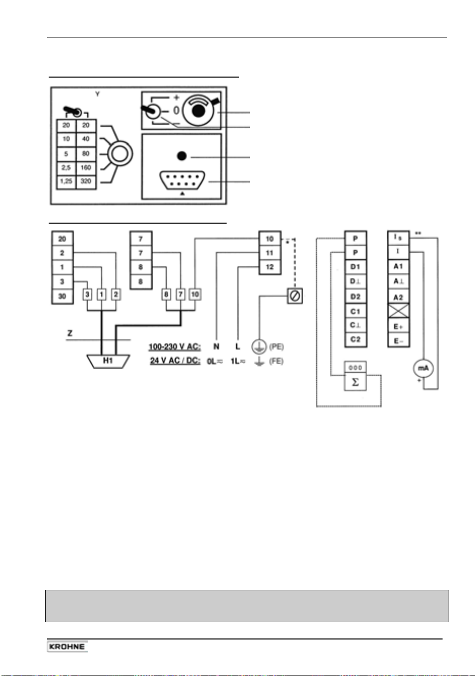
Part C Special applications, functional checks, service, and order numbers Sect. 7.7
7.7 Checking the signal converter using a GS 8 A simulator (optional)
GS 8 A operating elements and accessories
Connection of GS 8 A to signal converter
P
D
L
H
D
switch,
flow direction
H socket for plug H1
of cable Z
H1 plug of cable Z
L
power supply ON
P
potentiometer ”zero”
Y
switch,
measuring ranges
Z
cable between GS 8 A
and signal converter
active operation
* *
Switch off the power supply before starting work.
1) Remove the cover from the terminal compartment of the signal converter.
2) Disconnect all flow sensor cables from terminals 1, 2, 3, 7, 8, 20 and 30, having first noted
down which cable is connected to which terminal.
3) Connect the GS 8 A to the signal converter as shown above.
4) Slip plug H1 of cable Z into socket H on the front panel of the GS 8 A.
5) Connect the mA meter to terminals I
/I: accuracy class 0.1
S
Ri = 15-500 W
range 0 / 4 - 20 mA
6) Connect the electronic totalizer to terminals P / P: range 0 - 10 kHz
time basis at least 1 s
For further details on the totalizer and its connection for active or passive modes of
operation please refer to the connection diagrams in Section 2.6.
7) Test as described on the following two pages.
8) When the test is completed, disconnect the GS 8 A and re-connect the flow sensor and
receiver instruments (items 4 to 1 above).
PLEASE NOTE
that an adapter is needed to connect the GS 8 simulator to the signal converter
(adapter Order No. 210764.00)
IFC 110 F 77
05/2003
Page 78

Sect. 7.7 Part C Special applications, functional checks, service, and order numbers
Checking the setpoint reading
1) Switch on the power supply and allow at least 15 minutes for ”warming up”.
Turn switch D (GS 8 A front panel) to ”0”.
2)
Adjust zero to 0 or 4 mA with the 10-turn potentiometer P (GS 8 A front panel), depending
3)
on the setting in Fct. 1.05, deviation <± 10 µA.
Calculate the position of switch Y and displayed setpoints ”I” and ”f”.
4)
4.1) X =
Q100% × K
GK × DN²
full-scale range (100%) in unit volume V per unit time t
Q
100%
GK flow sensor constant, see instrument nameplate
DN meter size DN in mm, not inches, see instrument nameplate
t
time in seconds (sec.), minutes (min.) or hours (h)
V unit volume
K constant according to the following table
t
Sec min h
V
liters 25 464 424.4 7.074
m³ 25 464 800 424 413 7 074
US Gallons 96 396 1 607 26.78
Determine position of switch Y:
4.2)
comes closest to factor X and meets condition Y ≤ X.
4.3) Calculate setpoint reading ”I” for current output:
use table (GS 8 A front panel) to determine value Y which
Y
I = I0% +
X
(I
- I0%) in mA
100%
I0% current (0/4mA) at 0% flow rate
I
Calculate setpoint reading ”f” for pulse output:
4.4)
P
current (20mA) at 100% flow rate
100%
Y
f =
100%
× P
X
100%
pulses per second (Hz)
in Hz
at 100% flow rate
Turn switch D (GS 8 A front panel) to ”+” or ”-” (forward/reverse flow).
5)
Set switch Y (GS 8 A front panel) to the value determined as described above.
6)
Check setpoint readings I and f, see items 4.3 and 4.4 above.
7)
8) Deviation < 1.5 % of setpoint. If higher, replace signal converter, see Section 8.7.
9) Linearity test: set lower Y values, readings will drop in proportion to the calculated
values for Y.
Switch off power supply after completing the test.
10)
11) Disconnect the GS 8 A.
12) Re-assemble in reverse order (items 2 to 1 ”in connection of GS 8A”).
See also illustration in Section 8.1 and 8.7.
13) The system is ready for operation after the power supply is switched on again.
Example: see next page.
78 IFC 110 F
05/2003
Page 79

Part C Special applications, functional checks, service, and order numbers Sect. 7.7
Example
Full-scale range
Meter size
Current at Q
Q
Pulses at Q
0%
100%
100%
Flow sensor constant
Constant
(V in m³)
(t in h) K
(DN in mm)
Q
100%
DN
I
0%
I
100%
P
100%
GK
= 200 m³/h (Fct. 1.01)
= 80 mm = 3 inch (Fct. 3.02)
= 4 mA
= 20 mA
= 200 pulses/h (Fct. 1.06)
}
(Fct. 1.05)
= 3.571 (see instrument nameplate)
= 7074 (see table)
Calculation of ”X”
and setting of ”Y”
100% x K 200 x 7074
X =
Q
GK x DN2 = 3.571 x 80 x 80
= 61.905
Y = 80, setting of switch Y, see GS 8 A front panel
(comes closest to the value of X and is smaller than X).
Calculation of setpoint readings I and f
I = I
Y 40
0%
+
X
(I
- I0%) = 4 mA +
100%
61.905
(20mA - 4mA) = 14.3mA
Deviations are permissible between 14.1 and 14.6 mA
(equivalent to ± 1.5 %).
Y 40
f =
X
x P
100%
=
61.905
x pulses / h = 180.9 pulses/h
Deviations are permissible between 178.2 and 183.6 pulses/h
(equivalent to ± 1.5 %).
If you need to return your flowmeter to KROHNE,
please refer to the last-but-one page of these instructions.
IFC 110 F 79
05/2003
Page 80

Sect. 8.1 Part C Special applications, functional checks, service, and order numbers
8 Service
8.1 Replacing the power supply fuse
Switch off the power supply before opening the housing.
1)
Remove the cover from the terminal compartment (remove 2 screws).
2) Unscrew the cap of the power supply fuse F.
3)
Replace fuse F5 or F6, type 5 x 20 G (Order No. see Sect. 9).
F5: value for 100-230 V AC
F6: value for 24 V AC / DC
F5/F6
FP
I/O
power supply fuses, values are indicated above
plug-in terminal for field current supply line, 4-pin
plug-in terminal for outputs and inputs, 2x8-pin
PE/FE U-clamp terminal for connecting protective conductor PE or functional grounding
conductor FE
PS
RS
S
SC
plug-in terminal for power supply line, 3-pin
plug-in terminal for interface(s)
U-clamp terminal for connecting the signal line shielding:
signal line A: 2nd shield (7)
signal line B: 3rd shield (11)
plug-in terminal for electrode signal line, 5-pin
S-EEx Same as “S”, only available for hazardous duty version
W
internal connection, may not be removed.
0.8 A T, breaking capacity 1500 A
1.6 A T, breaking capacity 150 A
I/O
RS
80 IFC 110 F
05/2003
Page 81

Part C Special applications, functional checks, service, and order numbers Sect. 8.2
8.2 Retrofitting of magnetic sensors MP (optional)
Switch off the power supply before opening the housing.
1)
Remove the cover from the terminal compartment (remove 2 screws).
2)
Pull all cables out of the plug-in terminals.
3)
Remove the glass cover from the control compartment (remove 4 screws).
4)
Remove 4 screws from the front panel F, take hold of the handle on the upper end of the
front panel and carefully pull the complete electronic unit out of the signal converter housing.
5)
Put down the electronic unit with the front panel F facing down (see illustration on the next
but one page).
6)
Position the 2 mm (0.08”) thick insulating strip (Order No. 3 15940.01) loosely on top of the
MP printed circuit board (PCB). The magnetic sensors and chip capacitor slip into the 4
holes in the insulating strip. Slip the MP PCB and insulating strip from right to left between
the front panel and BDE PCB, taking care that the MP PCB and insulating strip are slipped
through the three retaining clips H at the back of front panel F. Slip the socket connector of
the MP PCB onto the (5-pin) plug connector PL
7) Fix the MP PCB with special steel tooth lock washer and nut SMP to establish contact
between the back of the PCB and the back of the front panel. When correctly fitted, the MP
PCB must be slightly bent between the final retaining clip H and the plug connector PLMP.
8)
Re-assemble in reverse order (items 4 to 1 above).
9) Switch on the power supply. The ”magnet active” LED on the front panel is green.
The function of the corresponding keys is tripped by touching the glass pane above the
3 white fields ”→, ↵ and ↑” with the bar magnet. The LED lights up red, see Section 4.2,
items
and .
MP
.
IFC 110 F 81
05/2003
Page 82

Sect. 8.3 Part C Special applications, functional checks, service, and order numbers
8.3 Replacing the complete electronic unit of the IFC 110 F signal converter
Switch off the power supply before opening the housing.
1)
Remove the cover from the terminal compartment (remove 2 screws).
2)
Pull all cables out of the plug-in terminals.
3)
Remove the glass cover from the control compartment (remove 4 screws).
4)
Remove 4 screws from the front panel F, take hold of the handle on the upper end of the
front panel and carefully pull the complete electronic unit out of the signal converter housing.
5) Carefully remove the data EEPROM IC 14 (on ADC printed circuit board) from the old
electronic unit and move it to the new electronic unit. Observe the direction of the IC when
plugging the data EEPROM. After changing the EEPROM from the old to the new electronic
unit, no further adjustments or settings are required. Refer to the drawing on the next page
and to the illustrations of the printed circuit boards in Section 8.7.
6)
Re-assemble in reverse order (items 4 - 1 above).
ADC
printed circuit board of A/D converter (ADC)
BDE
motherboard
F
front panel
F5
power supply fuse for 100 – 230 V AC,
see Sect. 8.1 and 9
F6
power supply fuse for 24 DC/AC,
see Sect. 8.1 and 9
FSV
printed circuit board for field current supply
H
3 retaining clips at the back
of the front panel
IC 14
data EEPROM (8-pin)
I/O
printed circuit board for outputs and inputs
MP
printed circuit board for magnetic sensors
(optional), see Sect. 6.2 and 8.2
NT
printed circuit board for power unit
OP
connection plug for additional modules
PLMP
5-pin plug connector for connection of the
printed circuit board MP for the magnetic
sensors
S
7 nuts for fastening the electronic unit
to front panel F
SLP
screws for fastening the PCBs
SMP
nut and special steel tooth lock washer
for fixing the MP PCB for the
magnetic sensors
82 IFC 110 F
05/2003
Page 83

Part C Special applications, functional checks, service, and order numbers Sect. 8.4
8.4 Replacing single printed circuit boards (PCBs)
Switch off the power supply before opening the housing.
1)
Remove the cover from the terminal compartment (remove 2 screws).
2)
Pull all cables out of the plug-in terminals.
3)
Remove the glass cover from the control compartment (remove 4 screws).
4) Remove 4 screws from the front panel F, take hold of the handle on the upper end of the
front panel and carefully pull the complete electronic unit out of the signal converter housing.
5) Put down the electronic unit with the front panel F facing down.
6) Remove screw(s) S
from the PCB(s) to be replaced and carefully pull the PCB(s) out of the
LP
plug base(s). Fit new PCB(s), refer to the illustration in Sect. 8.3 (preceding page).
• When replacing the PCBs FSV and/or ADC, always remove both PCBs together as
they have a common plug-and-socket connector.
• When replacing the ADC PCB, carefully move the data EEPROM IC 14 from the old to
the new PCB and observe the direction of the IC during plugging. After changing the
EEPROM from the old to the new electronic unit, no further adjustments or settings are
required. Refer to the illustration in Section 8.7.
7)
Re-assemble in reverse order (items 6 - 1 above).
8.5 Replacing the flow sensor
Switch off the power supply before beginning work.
1)
Before removing the ”old” flow sensor please note down which cable is connected to which
terminal.
2)
Install the new flow sensor as described in the installation instructions supplied with the
instrument.
3)
Electrically connect the flow sensor to the signal converter as described in these installation
and operating instructions, see Sections 1.3.5 and 1.3.6.
4)
During factory calibration, specific calibration data are determined for each flow sensor which
are indicated on the instrument nameplate. These data include the primary constant GK and
the magnetic field frequency which must be reset in Fct. 3.02 FLOW METER, subfunctions
”GK VALUE” and ”FIELD FREQ.”, see Sections 4.4 and 5.13.
5)
If the meter size of the flow sensor has changed, also reset the full-scale range Q
100%
and
the meter size in Fct. 3.02 FLOW METER, subfunctions ”DIAMETER” and ”FULL SCALE”,
see Sections 4.4 and 5.13.
6)
Perform zero test as described in Section 7.1 after the signal converter is reset.
7)
Reset the internal electronic totalizer of the signal converter as described in Sect. 4.6 if
necessary.
8.6 IFC 110 F replacements for old KROHNE signal converters
The IFC 110 F can replace all older KROHNE signal converter versions:
TIV 60 F / T 900 F / SC 100 A/F / SC 100 AS/F
This also applies to systems up to the size of DN 3000 / 120” that are operated with a power
driver. Such replacements are delivered together with any new wiring diagrams and additional
instructions for installation and setting of the IFC 110 F. You are kindly requested to comply with
these instructions.
IFC 110 F 83
05/2003
Page 84

Sect. 8.7 Part C Special applications, functional checks, service, and order numbers
8.7 Illustration printed circuit boards (PCBs)
110 - 230 AC 24 V DC / AC Description
X2 X1
X1 X2
F5 F6
Small fuses TR5 (values and order No. see Sect. 9)
F3 F5
F4 F3
F7 F4
F1 -
PCB 110 - 230 V AC
X2
F5
Plug-in terminal inside terminal compartment
Internal connection to mother board
Power supply fuse (typ, value and order No. see Sect. 9)
5 V voltage
Field current supply
Current output and power for passive operation of outputs
Coupling element
F1
F3
X1
F7
PCB 24 V DC / AC
X1
F6
F4
F5
X2
F4
TR1
F3
84 IFC 110 F
05/2003
Page 85

Part C Special applications, functional checks, service, and order numbers Sect. 8.7
Analog/digital converter PCB, (ADC)
EPD
X1
X2
X4
IC 11
Analog/digital converter PCB, rear side (detail)
internal connection to motherboard
plug-in terminals in terminal compartment
multipoint connector
peripheral IC
incl. control program
IC 12
IC 14
D3
D4
EPD
microprocessor
data EEPROM
green LED on front panel
red LED on front panel
empty pipe detection
S1
S2
S4
solder bridges for steady output signals
when measuring tube is empty,
}
see Sect. 6.8
IFC 110 F 85
05/2003
Page 86

Sect. 8.7 Part C Special applications, functional checks, service, and order numbers
Inputs/outputs PCB, I/O
Jumper X3 + X6 Jumper X4
X3
+
X6
active operation
+
X3
+
+
X6
passive operation
DC operation ≤ 0.2 A
AC operation ≤ 0.1 A (factory setting)
X1
X2
X4
X5
IC 11
IC 12
X3/X6
HART
plug-in terminals inside terminal compartment Small fuses TR 5, values and Order
internal connection to motherboard No. see Section 9
jumper, change-over of AC/DC operation
of output A1, see Sect. 6.3
multipoint connector
control program EPROM
microprocessor
jumper for active or passive operation
of current output
®
/ RS 485 PCB
X1
IC1
IC3
IC18
F1 P
F2 A1
F3 A2
F4 D1
F5 A2
F6 C1
F7 C2
F8 E+
F9 E–
X1 internal connection to mother board F1, F2, F3
X2 plug-in terminal inside terminal IC _ _
compartment
S3, S4
terminals
F1
F2
S3
S4
small fuses TR5
integrated circuit
solder bridges
F3
86 IFC 110 F
05/2003
Page 87

Part C Special applications, functional checks, service, and order numbers Sect. 9
9 Order numbers
Spare parts Order No.
Electronic unit with display
24 V AC / DC without magnetic
Power supply fuses:
(5 × 20 G fuse, breaking capacity 1500 A)
(5 × 20 G fuse, breaking capacity 150 A)
Various small fuses TR5
• I/O PCB (inputs/outputs)
• NT PCB
100 – 230 V AC 24 V AC/DC
(power unit) F3, F4 F3, F5 T 630 mA 5080190000
F7 F4 T 500 mA 5075860000
F1 – T 50 mA 5075780000
plug-in terminals 3-pin power supply
(printed and coded)
8-pin outputs D and P, inputs C
8-pin outputs A and I, internal power supply E
4-pin field current supply
5-pin signal line
RS 232 adapter incl. CONFIG operator software
(from version V 3.1 onwards)
for operator control of signal converter by MS-DOS PC or laptop
Conversion kit MP for magnetic sensors (complete retrofitting kit)
Bar magnet for operating the magnetic sensors
Flow sensor simulator GS 8 A
Adapter to make older versions of GS 8 simulators suitable for use
with IFC 110 F 2107640000
Glass cover for housing
Sealing material for housing cover, by the metre
ADC PCB (A/D converter)
I/O PCB (inputs/outputs)
FSV PCB (field current supply)
NT PCB (power unit) 100-230 V AC
NT PCB (power unit) 24 V AC / DC
HART / RS 485 PCB
100-230 V AC without magnetic
2135520100
sensors
100-230 V AC with HART / RS 485
2135520300
2135520700
sensors
F5: 100-230 V AC 0.8 A T
F6: 24 V AC/DC 1.6 A T
5080850000
5119230100
F2, F8
F1, F3-F7, F9
T 250 mA 5075640000
T 160 mA 5075900000
3161180100
3160220100
3160230200
3160200100
3160210100
German
English
V 035100131
V 035100132
V 150100004
2070530000
2070680200
2106730000
3137030000
VX 2134250100
VX 2115140100
VX 2135520200
2127970100
2133330100
2134310100
IFC 110 F 87
05/2003
Page 88

Sect. 10.1 Part D Technical Data, Measuring Principle and Block Diagram
10 Technical data
10.1 Signal converter
Mode of operation and system structure
Measurement principle Faraday’s law of induction
Modularity Measuring system consisting of
Measured variable Volumetric flowrate
Electrical conductivity of product
Versions
IFC 110 F / D (standard) Display version, with local display / control elements (15 keys)
IFC 110 F / D / MP (option) same as display version, additionally with magnetic sensors (MP) to control
IFC 110 F / D / MP / _ EEx (option) ATEX-EEx version for hazardous areas, PTB 02 ATEX 2163 X
Interfaces – HART
– RS 485 / PROFIBUS
Add-on equipment – CONFIG software and adapter for operator control via MS-DOS-PC,
Full-scale range
Flowrate for Q = 100% 6 Liter/h to 86 860 m³/h or 0.03 to 401 080 US Gal/min,
corresponding to flow velocity v = 0.3 – 12 m/s or v = 1 to 40 ft/s
Units m³/h, liter/s, US Gal/min or user-defined unit, e. g. liter/day or US Gal/day
Input / output circuits
Nominal voltages
Active / passive/ mode connection to protective extra-low voltage (PELV)
Current output
Function – all operating data configurable
– galvanically isolated from all input and output circuits
Current: fixed ranges 0 – 20 mA and 4 – 20 mA
variable ranges for Q = 0% I
for Q = 100% I
for Q > 100% I > 20 – 22 mA (maximum)
Load – active operation
– passive operation
Error identification 0 / 22 mA and variable
Forward/reverse flow measurement direction identified via status output
Pulse outputs (passive) P A1 (can also be operated as status output)
Function – for electronic totalizers – for electromechanical totalizers
– all operating data settable – all operating data configurable
Terminals P / P
Pulse rate 0 – 10 000 pulses per 0 – 50 pulses per
s [= Hz], min, h, m³, liter, etc., s [= Hz], min, h, m³, liter, etc.,
any scaling any scaling
Electrical data galvanically isolated galvanically isolated, but not from A2
note polarity
Pulse width automatic: pulse duty cycle 1:1, max. 10 000 pulses/s = 10 kHz
1
digital pulse division, interpulse period non-uniform, therefore if frequency
and cycle meters connected allow for minimum counting interval:
1000
Forward/reverse flow measurement direction identified via status output
signal converter and flow sensor
(electrode voltage from flow sensor)
≥ 5 µS/cm
≥ 20 µS/cm for demineralized cold water
the signal converter using bar magnet without opening the housing
®
add-on module
}
connection to internal IMoCom interface (equipment bus)
≤ 25 V AC / ≤ 50 V DC (safety value Um = 253 V)
= 0 – 16 mA
0%
= 4 – 20 mA
100%
adjustable in 1mA increments
}
min. 15 Ω
22 V DC ≤ U ≤ 32 V DC: R
15 V DC ≤ U ≤ 22 V DC: R
≤ 800 Ω
L
≤ 500 Ω
L
A1 / A ⊥
U ≤ 32 V DC / ≤ 24 V AC U ≤ 32 V DC / ≤ 24 V AC
I
≤ 30 mA, any polarity I
≤ 100 mA, any polarity
or U ≤ 32 V DC, I ≤ 200 mA
variable: 10 ms – 1 s, P
gate time, totalizer ≥
[pulses/s] = f
100%
[Hz]
P
100%
[Hz] =
max
2 x pulse width
88 IFC 110 F
05/2003
Page 89

Part D Technical Data, Measuring Principle and Block Diagram Sect. 10.1
Status outputs (passive) D1 / D2 / A2 A1 (can also be operated as pulse output)
Function, set for trip point trip point
flow direction flow direction
automatic range change automatic range change
error identification error identification
overdriving overdriving
empty pipeline empty pipeline
Terminals
Please note:
D1 / D2 / D ⊥ / A2 / A ⊥ A1 / A ⊥
D ⊥ common reference potential for D1 and D2
A ⊥ common reference potential for A1 and A2
Electrical data galvanically isolated galvanically isolated, but not from A2
U ≤ 32 V DC / ≤ 24 V AC U ≤ 32 V DC / ≤ 24 V AC
I
≤ 100 mA, any polarity I
≤ 100 mA, any polarity
or U ≤ 32 V DC, I ≤ 200 mA, note polarity
Control inputs C1 and C2 (passive)
Function, set for automatic range change, totalizer reset, error reset, start self-test,
set outputs to min. values or hold last measured values of outputs
Terminals
C1 / C ⊥ and C2 / C ⊥, galvanically isolated
Please note: C ⊥ common reference potential for C1 and C2
U = 8 – 32 V DC, I ≤ 10 mA, any polarity
Internal power supply for passive outputs and inputs and external receiver instruments
Terminals E + and E –, please note polarity, galvanically isolated
Electrical data
U = 24 V DC / R
Time constant 0.2 – 99.9 s, adjustable in increments of 0.1 second
Low-flow cutoff cutoff ”on“ value: 1 – 19 %
cutoff ”off“ value: 2 – 20 %
= approx. 15 Ohm / I ≤ 100 mA
i
of Q
}
, adjustable in 1% increments
100%
Local display and operation 3-line back-lit LCD
Display function actual flowrate, forward, reverse, sum totalizers (7 digits)
or 25-character bar graph with percent display and status messages
Units: actual flowrate m³/h, liter/s., US gallons/min or user-defined unit, e. g. hecto liter/h
totalizer m³, liter, or US gallons or user-defined unit (adjustable counting time till overflow)
Language of plain texts English, German, French, Swedish, others on request
Display: 1st line 8-character, 7-segment, numerical and sign display,
and symbols for key acknowledgement
2nd line 10-character, 14-segment, text display
3rd line 6 markers to identify display in measuring mode
Operation elements 15 keys or as option with 3 additionally magnetic sensors for operation without
opening the housing
Electrode circuit
Type of protection intrinsic safety [EEx ib IIC]
Max. values (cumulative) U
Kinked characteristic
Field power supply
= 18 V / I0 = 40 mA / P0 = 80 mW
0
capacitance C
≤ 225 nF / inductance L0 ≤ 5 mH
0
Type pulsed bipolar DC field for all KROHNE primary heads,
galvanically isolated from all input and output circuits
Terminals 2 x 7 and 8
Current / voltage
Clock frequency
± 0.125 A (± 5%) / U
1
/36 to ½ of power frequency,
≤ 40 V DC (frequency controlled)
N
configurable to the calibration data of the primary head
Internal fuse protection
Power supply AC version AC / DC version (switch-selectable)
I
≤ 160 mA
N
standard option, in preparation
Voltage range (without change over) 100 – 230 V AC 24 V AC 24 V DC
Tolerance band 85 – 255 VAC 20.4 – 26.4 V AC 18 – 31.2 V DC
Safety value Um = 253 V Um = 253 V Um = 253 V
Frequency 48 – 63 Hz 48 – 63 Hz –
Power consumption (incl. primary head)
18 VA, typical (max. 25 VA) 18 VA, typical (max. 25 VA) 18 W, typical (max. 18 W)
When connected to a functional extra-low voltage,
ensured (VDE 0100 / VDE 0106 and IEC 364 / IEC 536 or equivalent national standards).
24 V AC / DC
, protective separation (PELV) must be
Approvals and housing
Material of field housing die-cast aluminium with polyurethane finish
Ambient temperature • operation standard -25 to +60 °C / -13 to +140 °F
EEx -20 to +55 °C / - 4 to +131 °F
EEx, special “S” -40 to +55 °C / -40 to +131 °F
• storage all versions -40 to +60 °C / -40 to +140 °F
Protection category (IEC 529 / EN 60 529) IP 65, equivalent to NEMA 4 / 4X
EU_EMC Directives to EN 61326-1 (1977) and A1 (1998) directives and NAMUR Standard NE 21
Certificates and approvals II (2) G [EEx ib] IIC
PTB 02 ATEX 2136 X
IFC 110 F 89
05/2003
Page 90
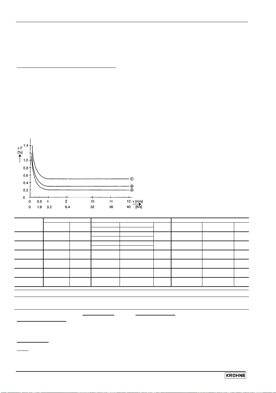
Sect. 10.2 Part D Technical Data, Measuring Principle and Block Diagram
10.2 Error limits
Display, digital values, pulse output
F
maximum error in % of measured value (MV),
v
Flow velocity in m/s and ft/s
Reference conditions similar to EN 29 104
Product water at 10 – 30°C/ 50 – 86°F
Electrical conductivity > 300 µS/cm
Power supply (rated voltage) U
Ambient temperature 20 – 22°C / 68-71.6 °F
Warm-up time 60 min
Max. calibration equipment error
Inlet / outlet runs
Flow sensor properly grounded and centered
Calibrated on EN 17025 accredit to calibration equipment in direct volumetric comparsion.
Flow Meter size Standard details
sensor
VARIFLUX
6000 F
PROFIFLUX
5000 F
ALTOFLUX
4000 F
ALTOFLUX
2000 F
ECOFLUX
1000 F
M 900
Current output
Reproducibility and
repeatability
External influences
DN mm inch
2.5- 6 1/10 - 1/4 ± 0.5% of MV ± 0.4% of MV + z
10 - 80 3/8 - 3 ± 0.3% of MV ± 0.2% of MV + z
2.5- 6 1/10 - 1/4 ± 0.5% of MV ± 0.4% of MV + z
10 - 100 3/8 - 4 ± 0.3% of MV ± 0.2% of MV + z
10. - 25 3/8 - 1 – –
32 -1600 11/4 -64
150 - 250 6 -10 ± 0.3% of MV ± 0.2% of MV + z
10 - 150 3/8 - 6 ± 0.5% of MV ± 0.4% of MV + z
10. - 25 3/8 - 1 – – –
32 - 300 11/4 -12
v ≥ 1.0 m/s
v ≥ 3.3 ft/s
± 0.3% of MV ± 0.2% of MV + z
± 0.3% of MV ± 0.2% of MV + z
same error limits as above, additionally ± 10 µA
0,1% of MV, minimum 1 mm/s / 0.04 inch/s at constant flow
typical values
Ambient temperature
Pulse output 0,003% of MV (1) 0,01 % of MV (1) per 1 K / 1.8° F
Current output 0,01 % of MV (1) 0,025% of MV (1)
Power supply
Load
< 0,01 % of MV 0,02 % of MV, at max. load, see Sect. 10.1
(1) All KROHNE signal converters undergo burn-in tests, duration minimum 20 hours at varying ambient temperatures
– 20 to + 60°C/– 4 to + 140°F. The tests are controlled by computers.
< 0,02 % of MV 0,05 % of MV at 10% variation
90 IFC 110 F
not
typical values
(± 2%)
N
10 × smaller than F
10 × DN / 2 × DN (DN = meter size)
*
VARIFLUX 6000 F (DN 2.5 – 4
and 1/10’’ – 1/6’’)
additional error ± 0,3% of MV
MV
Measured Value
z
= 1 mm/s = 0.04 inch/s
v < 1.0 m/s
v < 3.3 ft/s
Option
Curve
C
B
C
B
B
B
B
B
(extra charge)
v ≥ 1.0 m/s
v ≥ 3.3 ft/s
– – –
– – –
– – –
± 0.2% of MV ± 0.1% of MV + z
± 0.2% of MV ± 0.1% of MV + z
± 0.2% of MV ± 0.1% of MV + z
– – –
± 0.2% of MV ± 0.1% of MV + z
maximum values
}
temperature variation
v < 1.0 m/s
v < 3.3 ft/s
05/2003
Curve
A
A
A
A
Page 91

Part D Technical Data, Measuring Principle and Block Diagram Sect. 10.3
10.3 Dimensions and weights IFC 110 F / IFC 110 F-EEx and ZD / ZD-EEx
Dimensions in mm and inch
IFC 110 F Signal converters ZD Intermediate connection box
Weight approx. 4.1 kg / 9.0 lbs Weight approx. 0.5 kg / 1.1 lbs
10.4 Flow table
v = flow velocity in m/s and ft /s
Meter size Full-scale range Q
DN v = 0.3 m/s v = 1 m/s v = 12 m/s DN v = 1 ft/s v = 40 ft/s
mm inch
2.5 1/10 0.0053 0.0177 0.2121 1/10 2.5 0.0245 0.979
4 1/8 0.0136 0.4520 0.5429 1/8 4 0.0383 1.530
6 1/4 0.0306 0.1018 1.222 1/4 6 0.1530 6.120
10 3/8 0.0849 0.2827 3.392 3/8 10 0.3735 14.93
15 1/2 0.1909 0.6362 7.634 1/2 15 0.8405 33.61
20 3/4 0.3393 1.131 13.57 3/4 20 1.494 59.75
25 1 0.5302 1.767 21.20 1 25 2.334 93.34
32 - 0.8686 2.895 34.74 - 32 3.824 153.0
40 11/2 1.358 4.524 54.28 11/2 40 5.979 239.0
50 2 2.121 7.069 84.82 2 50 9.339 373.5
65 - 3.584 11.95 143.3 - 65 15.78 630.9
80 3 5.429 18.10 217.1 3 80 23.90 955.6
100 4 8.483 28.27 339.2 4 100 37.35 1493
125 - 13.26 44.18 530.1 - 125 37.35 2334
150 6 19.09 63.62 763.4 6 150 84.05 3361
200 8 33.93 113.1 1357 8 200 149.43 5975
250 10 53.02 176.7 2120 10 250 233.4 9334
300 12 76.35 254.5 3053 12 300 336.2 13442
400 16 135.8 452.4 5428 16 400 597.9 23899
500 20 212.1 706.9 8482 20 500 933.9 37345
600 24 305.4 1018 12215 24 600 1345 53781
700 28 415.6 1385 16625 28 700 1919 76760
800 32 542.9 1810 21714 32 800 2507 100272
900 36 662.8 2290 26510 36 900 3173 126904
1000 40 848.2 2827 33929 40 1000 3917 156672
1200 48 1221 4072 48858 48 1200 5640 225608
1400 56 1663 5542 66501 56 1400 7677 307080
1600 64 2171 7238 86859 64 1600 10027 401080
(minimum) (maximum)
IFC 110 F 91
05/2003
in m³/h Meter size Q
100%
inch mm
in US Gal/min
100%
(minimum) (maximum)
Page 92

Sect. 11 Part D Technical Data, Measuring Principle and Block Diagram
11 Measuring principle
The flowmeter is designed for electrically conductive fluids.
Measurement is based on Faraday’s law of induction, according to which a voltage is induced in
an electrically conductive body which passes through a magnetic field. The following expression is
applicable to the voltage:
U = K × B × v × D
K an instrument constant
B magnetic field strength
v mean velocity
D pipe diameter
Inside the electromagnetic flowmeter, the fluid passes
through a magnetic field applied perpendicular to the
direction of flow. An electric voltage is induced by the
movement of the fluid (which must have a minimum
electrical conductivity). This is proportional to the mean
flow velocity and thus to the volume of flow. The induced
voltage signal is picked up by two electrodes which are
in conductive contact with the fluid and is transmitted to
a signal converter for a standardized output signal.
This method of measurement offers the following advantages:
1) No pressure loss through pipe constriction or protruding parts.
2) Since the magnetic field passes through the entire flow area, the signal represents a mean
value over the pipe cross-section; therefore, only relatively short straight inlet pipes 5 x DN
from the electrode axis are required upstream of the flow sensor.
3) Only the pipe liner and the electrodes are in contact with the fluid.
4) Already the original signal produced is an electrical voltage which is an exact linear function
of the mean flow velocity.
5) Measurement is independent of the flow profile and other properties of the fluid.
The magnetic field of the flow sensor is generated by a square wave current fed from signal
converter to the field coils. This field current alternates between positive and negative values.
Alternate positive and negative flowrate-proportional signal voltages are generated at the same
frequency by the effect of the magnetic field, which is proportional to the current. The positive and
negative voltages at the flow sensor electrodes are subtracted from one another in the signal
converter. Subtraction always takes place when the field current has reached its stationary value,
so that constant interference voltages or external or fault voltages changing slowly in relation to
the measuring cycle are suppressed. Power line interference voltages coupled in the flow sensor
or in the connecting cables are similarly suppressed.
92 IFC 110 F
05/2003
Page 93
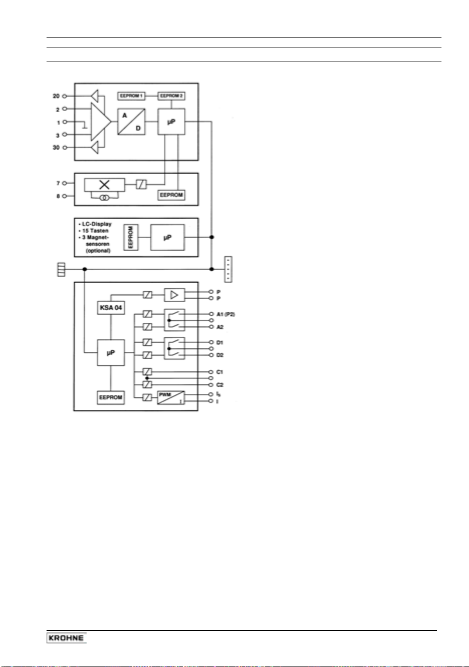
Part D Technical Data, Measuring Principle and Block Diagram Sect. 12
12 Block diagram
ADC printed circuit board, analog / digital
{
converter (terminals 1, 2, 3, 20 and 30)
Signal processor protected against overload,
•
for quick and precise processing of flow
peaks up to and exceeding 20 m/s or 60 ft/s.
Digital signal processor, sequential control
•
and test routines.
Patented high-resolution analog/digital
•
converter, digitally controlled and monitored.
Input amplifier allowing control of potential of
•
signal line shielding (bootstrap).
User parameter and internal calibration
•
values are stored in separate EEPROMs
(easily replaceable).
FSV printed circuit board, field current supply
|
(terminals 7 and 8)
Large signal-to-noise ratio owing to low-loss
•
field current supply with high frequencies and
high currents.
Pulsed direct current which is precisely
•
controlled electronically, for the magnetic coils
of the flow sensor.
Operating and calibrating data are stored in an
•
EEPROM so that the PCB can be easily
replaced without the need for re-calibration.
BDE printed circuit board, motherboard
}
Large illuminated LC display.
•
15 keys for operator control of signal converter
•
Can be retrofitted with optional operator
•
control by bar magnet.
Distribution of general signals such as
•
IMoCom bus, power supply.
I/O printed circuit board, inputs and outputs
~
Groups, inputs and outputs are galvanically
•
isolated from each other and from all other
circuits.
Power supply source for the inactive inputs
•
and outputs.
Specific KROHNE circuit KSA 04 for fine
•
quantization of output pulses across a wide
dynamic range.
Active current output I (e.g. 0/4-20 mA) with
•
load control.
Pulse output P for electronic totalizers, max.
•
10 Hz.
Pulse output A1 for electromechanical
•
totalizers, max. 50 Hz, can also be used as
status output A1.
Several status outputs A1, A2, D1, D2.
•
Control inputs C1 and C2.
•
IMoCom bus plug
Connecting external operating and testing devices,
e.g. RS 232 adapter and CONFIG software for
operator control of signal converter by MS-DOS
PC or laptop.
Slots for plug-in modules, for upgrading or
converting the signal converter
HART / RS 485 ancillary board
•
GTEX ancillary board for Ex-i operation of the
•
signal converter outside hazardous areas.
Other modules and ancillary boards in
•
preparation.
IFC 110 F 93
05/2003
Page 94

Sect. 13.1 Part D Technical Data, Measuring Principle and Block Diagram
13 Approvals
13.1 EC-type examination certificate English translation
94 IFC 110 F
05/2003
Page 95
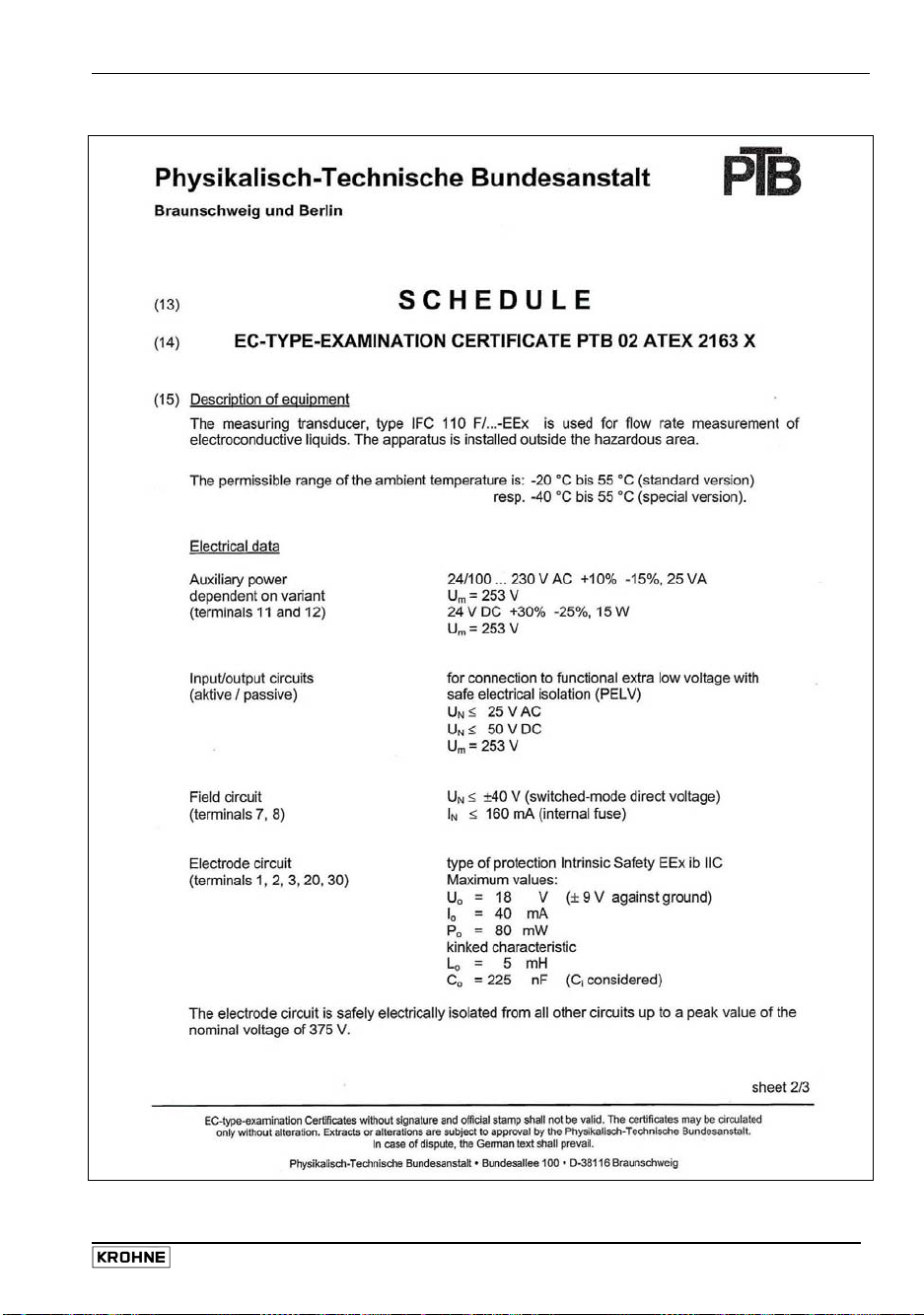
Part D Technical Data, Measuring Principle and Block Diagram Sect. 13.1
English translation
IFC 110 F 95
05/2003
Page 96

Sect. 13.1 Part D Technical Data, Measuring Principle and Block Diagram
English translation
96 IFC 110 F
05/2003
Page 97

Part D Technical Data, Measuring Principle and Block Diagram Sect. 13.2
13.2 EC-type examination certificate German original
IFC 110 F 97
05/2003
Page 98

Sect. 13.2 Part D Technical Data, Measuring Principle and Block Diagram
German original
98 IFC 110 F
05/2003
Page 99

Part D Technical Data, Measuring Principle and Block Diagram Sect. 13.2
German original
IFC 110 F 99
05/2003
Page 100

Sect. 14 Part E Index
14 Index
Keyword Sect. No. Fct. No. Keyword Sect. No. Fct. No.
A
A1 status or 2nd pulse output 2.3, 2.6, 1.07, 3.07
5.7, 5.18 F
A1/A2 status outputs 2.4, 2.6, 5.10 1.07, 1.08 F = forward flow 4.4, 5.1, 5.15 1.04-1.07, 3.02
Abbreviations 1.3.2, 1.3.4, Factory setting(s) 2.7
2.1, 4.1, 4.4 Fatal error 4.5
ADC see analog/digital converter FE = functional grounding conductor 1.1, 1.2, 1.3.3
Additional function = option 6.2, 6.4, 10.1 1.3.5, 1.3.6
Analog/digital converter 4.5, 11 Field current supply 5.13, 10.1
Applications 5.17 3.06 11, 12
Automatic range change 2.6, 5.20 1.05, 1.07-1.10 Flow
– pulsating 6.5, 6.6 3.06
B
Bar magnet 4.2, 6.2, 8.2 Flow constant GK 4.4, 5.13 3.02
Block diagram 12 Flow direction 4.4, 5.1, 5.15 3.02
BTS, bootstrap signal line B 1.3 Flow rate (Q) 4.4, 5.1 3.02
Flow sensor
C
C1/C2 control inputs 2.5, 2.6, 5.9 1.11, 1.12 – replacement 8.5
Cable length 1.3.4 – testing 7.6
Characteristic of outputs 5.16 Flow simulator GS 8 A 7.7
Code for entering setting level 5.12 3.04 Flow velocity (v) 4.4, 5.1 3.03
Connection and operating points 4.2 Frequency output see pulse output 2.3, 5.7 1.06
– front panel 8.7 Full-scale range Q100% 4.4, 5.1 1.01, 3.02
– printed circuit boards Functional check
Connection diagrams – hardware information 7.3 2.02
– GS 8 A simulator 7.7 – measuring range 7.2
– inputs/outputs 2.6 – primary head 7.6
– power supply 1.3.5, 1.3.6 – signal converter 7.7
– primary head 1.3.5, 1.3.6 – setpoint readings 7.7
Control inputs C 2.5, 4.4, 5.9 – system 7.5
Conversion factor 4.4, 5.14 – zero 7.1 3.03
– volume 4.4, 5.14 3.05 Functional grounding conductor FE 1.1, 1.2, 1.3.3
– time 3.05 1.3.5, 1.3.6
Current output I 2.2, 5.6 Function level 4.1 1.01 et seq.,
2.01 et seq.,
D
D1/D2 status outputs 2.4, 2.6, 5.8 1.09, 1.10 Function of keys 4.1, 4.3
Data 4.4 Function(s) 4.4
Data error 4.5 Fuses (F) 8.1, 8.7, 9
Data level 4.1-4.3
Delete error messages 4.6
Dimensions 10.3 GK primary head constant 4.4, 5.13 3.02
Disconnection 2.1 Grounding
Display 4.2, 5.5 1.04 – primary head 1.3.3
– language 4.4, 5.11 3.01 – signal converter 1.2, 1.3
– unsteady 6.6 – system 1.2-1.3
DS signal line A 1.3 GS 8 A primary simulator 7.7
E
E+/E- internal power supply for Hardware
inputs/outputs 2.1, 2.5, 5.10 – information 7.3 2.02
EC electronic totalizer 2.3, 2.6, 5.9 1.06 – setting(s) 5.18 3.07
EEx version 1.3.6, 6.1, 10.1 – test 7.4 2.03
Electrical connection
– GS 8 A simulator 7.7 Hazardous areas 1.3.6, 6.1, 10.1
– inputs 2.6 page 5
– outputs 2.6
– power supply 1.3.5, 1.3.6
Electromagnetic compatibility page 5 I = current output 2.2, 5.6 1.05
Electromechanical totalizer 2.3, 5.7 1.07, 3.07 IEC standards page 5
Electronic totalizer 2.3, 5.7 1.06 IMoCom bus (plug) 6.4, 8.7, 11
EMC electromechanical totalizer 2.3, 2.6 ImoCom software 6.4.1
5.7, 5.17 1.07, 3.06 Inputs/outputs
Empty pipe detection EPD 6.9 – characteristics 5.16
Entry (programming) 4 – connection diagrams 2.6
EPD (empty pipe detection) 6.9 – setting 4.4
Error 4.5 — control inputs 5.9 1.11, 1.12
Error list 4.5 — current output 5.6 1.05
Error (messages) — pulse outputs 5.7 1.06, 1.07, 3.07
– eliminate 4.5 — status outputs 5.8 1.07-1.10, 3.07
– limits 10.1 – steady voltage with empty tube 5.7
– reset (delete) 4.6 Interfaces 6.4, 10.1
– search 7.1 et seq. Intermediate connection box (ZD) 1.4, 10.3
EU standards page 5 Internal power supply (E+/E-) 2.1, 2.6, 5.10
External totalizer 2.3, 2.6, 5.7 1.06, 1.07
– quickly changing 6.6, 6.7
– constant GK 4.4, 5.13 3.02
3.01 et seq.
G
H
HART® interface
I
6.4.2
100 IFC 110 F
05/2003
 Loading...