

Page 1
KROHNE 08/2003 US size: 7.02264.71.00
©
DIN A4: 7.02264.31.00
Installation and
operating instructions
IFC 110 F V2.0
IFC 110 F-EEx V2.0
Signal converters for
electromagnetic flowmeters
Applicable to
Software Versions
How to use these Instructions
Flowmeters are delivered ready for operation.
The flow sensor must be installed in the pipeline as described in the instructions for
installation inside the packing of the flow sensor.
– Connection of power supply (Sect. 1.1-1.2) Pages 4- 5
– Electrical connection between IFC 110 F and primary head (Sect. 1.3) Pages 6-13
– Electrical connection of outputs and inputs (Sect. 2) Pages 14-22
– Start-up (Sect. 3) Pages 23
Power the flowmeter. THAT’S ALL. The system is operative.
Operator control of the IFC 110 F signal converter is described in Sect. 4.
● Display & control unit
No. 3.19937.02.00
● A/D converter
No. 8.13393.02.00
● Outputs/inputs (I/O)
No. 3.16230.01.00
Variable area flowmeters
Vortex flowmeters
Flow controllers
Electromagnetic flowmeters
Ultrasonic flowmeters
Mass flowmeters
Level measuring instruments
Communications technology
Engineering systems & solutions
Switches, counters, displays and recorders
Heat metering
Pressure and temperature
Page 2
A
The operating data are factory-set to your ordered specifications.
Signal converter versions
IFC 110 F / D Standard version, with local display and control elements
(Standard)
IFC 110 F / D / MP Same as display version, additional with magnetic sensors (MP)
(Option)
IFC 110 F / D / MP / EEx Same as display version (D + MP),
(Option) for operation with flow sensors installed in hazardous areas
IFC 110 F / RS 485 Same as standard version,
but additionally with different interfaces
• Signal converter in the version as ordered, see above.
Items included with supply
• Signal cable in the version and length as ordered (standard: signal cable A,
length 10 m / 30 ft)
• Condensed installation and operating manual in the ordered language for installation,
electrical connection, start-up and operator control of the signal converter.
• Service Manual in english language.
Please note!
In the Installation and Operating Manual there are hints with Sect. Numbers which you can find
in the Handbook / Service Manual only!
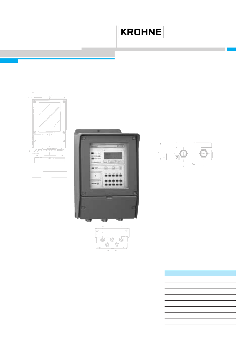
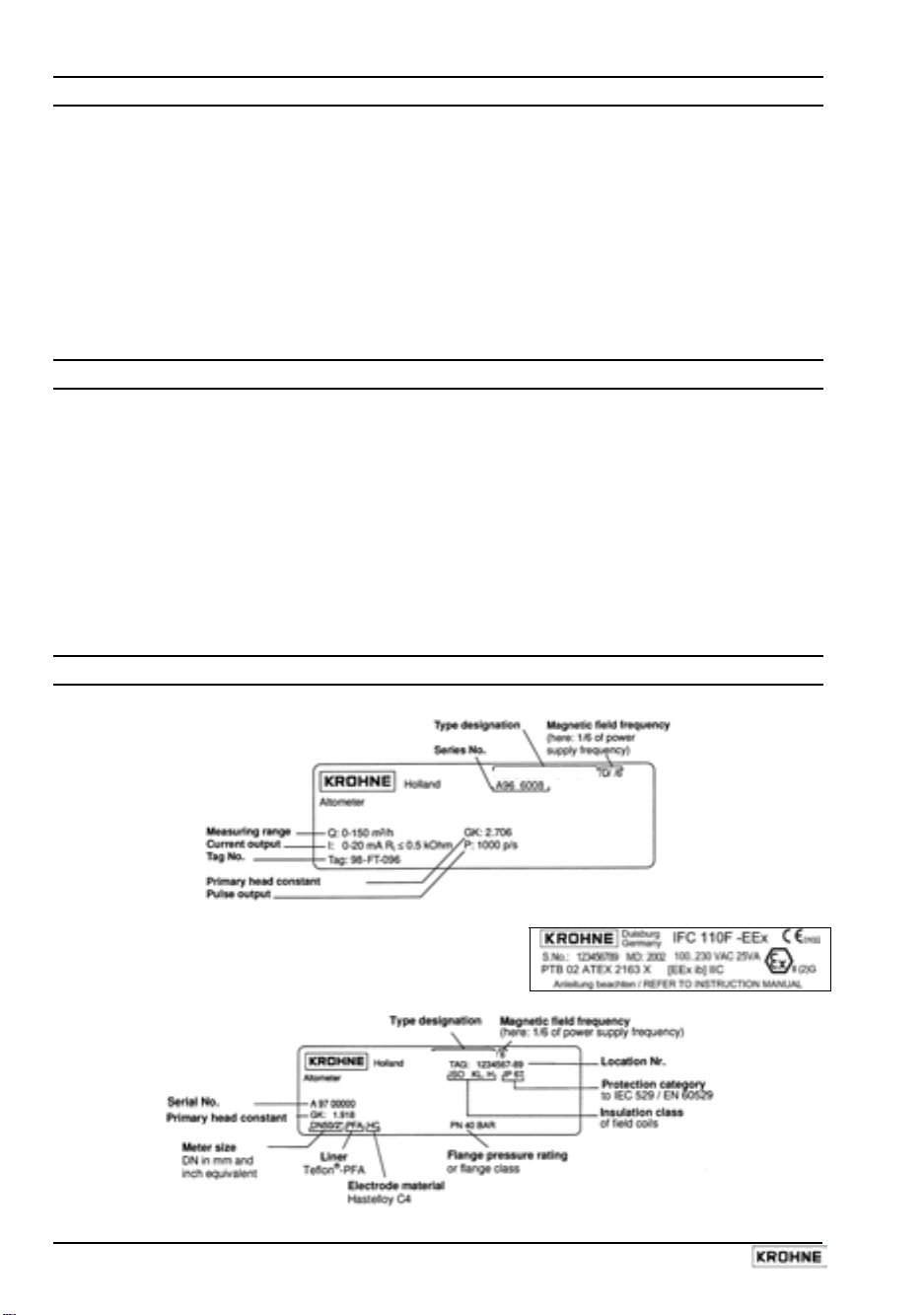
Instrument nameplates
Signal converter (example)
IFC 110 F
Signal converter IFC 110F-EEx (example)
Flow sensor (example)
LTOFLUX 4000 F
2 IFC 110 F
05/2003
Page 3
System description
Electromagnetic flowmeters are precision instruments designed for linear flow measurement of
liquid products
The process liquids must be electrically conductive:, ≥ 5 µS/cm
(for cold demineralized water ≥ 20 µS/cm).
The full-scale range Q
can be set as a function of the meter size: flow velocity of 0.3 - 12 m/s
100%
or 1 - 40 ft/s (s. Section 10.4.).
Product liability and warranty
The electromagnetic flowmeters are designed solely for measuring the volumetric flowrate of
electrically conductive, liquid process products.
These flowmeters are available for use in hazardous areas.
Special regulations apply in this case, which are given in the special EEx directions.
Responsibility as to suitability and intended use of these electromagnetic flowmeters rests
solelywith the operator.
Improper installation and operation of the flowmeters (systems) may lead to loss of warranty.
In addition, the “General conditions of sale” forming the basis of the purchase contract are
applicable.
If flowmeters need to be returned to KROHNE, please note the information given on the last-butone page of these Instructions. KROHNE regrets that it cannot repair or check your flowmeter(s)
unless accompanied by the completed form sheet.
CE / EMC / Standards / Approvals
The here described Electromagnetic flowmeters meet the NAMUR Directive NE21,
the protection requirements of Directive 89/336/EEC in conjunction with EN
61326-1 (1997) and A1 (1998), as well as Directives 73/23/EEC and 93/68/EEC
in conjunction with EN 61010-1, and bear the CE marking.
Software history
Display & control unit Amplifier (ADC) Inputs and outputs (I/O)
Software Status Software Status Software Status
3.19937.02.00
current
IMPORTANT!
In respect of EEx versions, pay regard to all directions marked with the
and also the information given in Sect. 6.1 and 13.
Only the EEx flow sensor may be installed in the hazardous area. The EEx
certified signal converter must be installed outside the hazardous area!
8.13393.02.00
current
3.16230.01.00
current
symbol,
IFC 110 F 3
05/2003
Page 4

1 Electrical connection: power supply
1.1 Location and important installation notes ……………………. PLEASE NOTE !
• Electrical connection in accordance with VDE 0100 ”Regulations for the erection of power
installations with nominal voltages up to 1000 V” or equivalent national regulations.
• Do not cross or loop cables inside the terminal compartment.
• Use separate wiring (PG screwed cable entries) for power supply, field current lines, signal
lines, outputs and inputs.
• Hazardous areas are subject to special regulations, see Section 6.1 and special installation
instructions for hazardous-duty versions.
• Do not expose signal converter and switchgear cabinets with built-in converters to direct
sunlight. Install a sunshade if necessary.
• Signal converters installed in switchgear cabinets require adequate cooling (e.g. by fans
or heat exchangers).
• Do not expose signal converters to intense vibration.
• Keep the distance between the flow sensor and signal converter as small as possible, for
empty pipe detection (EPD) ≤ 20 m / ≤ 66 ft. Observe maximum lengths of signal and field
current lines (see Section 1.3.4).
• Use KROHNE signal line A (type DS, standard) or signal line B (type BTS, bootstrap,
optional), standard length 10 m (33 ft).
• Generally use bootstrap signal lines B (type BTS) for PROFIFLUX 5000 F and VARIFLUX
6000 F flow sensors sized at DN 2.5-15 and 1/10’’-1/2’’ and for contaminated liquids which
tend to form electrically insulating deposits.
• Always calibrate flow sensor and signal converter together. During installation particular care
should therefore be given to identical settings of flow sensor constant GK (see instrument
nameplate of flow sensor). In case GK constants are not identical, the signal converter must
be adjusted to the flow sensor GK (see Sections 4 and 8.5).
• Dimensions of signal converter see Section 10.3.
IMPORTANT!
For EEx versions, also pay regard to all directions included in Sect. 6.1 and 13.
Only the EEx flow sensor may be installed in the hazardous area. The EEx
certified signal converter must be installed outside the hazardous area!
4 IFC 110 F
05/2003
Page 5

1.2 Power supply - connection
PLEASE NOTE !
• Type of enclosure
• Dimensioning:
moisture must always be kept closed. The selected clearances and creeping distances comply
with VDE 0110 and/or IEC 664 regulations for contamination grade 2. Supply circuits and
output circuits are designed to meet standards of overvoltage classes III and II, respectively.
• Fuse protection, disconnecting device: fuse protection for the feeding power circuit, and also a
disconnecting device (switch, circuit breaker) for isolating the signal converters must be
provided (see also Sect. 1.3.5 and 1.3.6).
100-230 V AC (tolerance range 85-255 V AC)
• Observe information on the instrument nameplate, power supply voltage and frequency.
• The protective conductor PE of the power supply must be connected to the separate
U-clamp terminal inside the terminal compartment of the signal converter.
• CAUTION: do not remove the internal connection (line) inside the terminal compartment of the
signal converter (yellow/green wire) between the U-clamp terminal and terminal 10 protective conductor (protection class I instrument).
• Connection diagrams I - IV for the power supply and for the electrical connection between
flow sensor and signal converter, see Sections 1.3.5 (Standard) and 1.3.6 (EEx).
24 V AC / DC (tolerance ranges: AC 20.4 - 26.4 V / DC 18 - 31.2 V)
• Observe information on the instrument nameplate, power supply voltage and frequency.
• For technical reasons concerning the measuring process, a functional grounding conductor
FE has to be connected to the separate U-clamp terminal inside the terminal compartment of
the signal converter.
• A facility providing a reliable electrical separation (PELV) has to be provided for connections
to functional extra-low voltages (24 V AC / DC) - (VDE 0100 / VDE 0106 and/or IEC 364 /
IEC 536 or equivalent national regulations).
• Connection diagrams I - IV for the power supply and for the electrical connection between
flow sensor and signal converter, see Sections 1.3.5 (Standard) and 1.3.6 (EEx).
Warning: Instrument must be properly grounded to avoid personnel shock hazard.
IP 65 to IEC 529 / EN 60529 equivalent to NEMA 4/4X.
the flowmeter housing protecting the electronic equipment against dust and
IMPORTANT!
For EEx versions, also pay regard to all directions included in Sect. 6.1 and 13.
Only the EEx flow sensor may be installed in the hazardous area. The EEx
certified signal converter must be installed outside the hazardous area!
IFC 110 F 5
05/2003
Page 6
1.3 Electrical connection of flow sensors
1.3.1 General remarks on signal lines A and B and field current line C
Proper operation of the equipment is ensured when KROHNE signal lines A and B are used with
foil screen and magnetic shield.
• Signal lines must be firmly installed.
• Shields are connected via stranded drain wires.
• Underwater or underground routing is possible.
• Insulating material flame-retardant to IEC 332.1 / VDE 0742.
• Low-halogen, unplasticized signal lines which remain flexible at low temperatures.
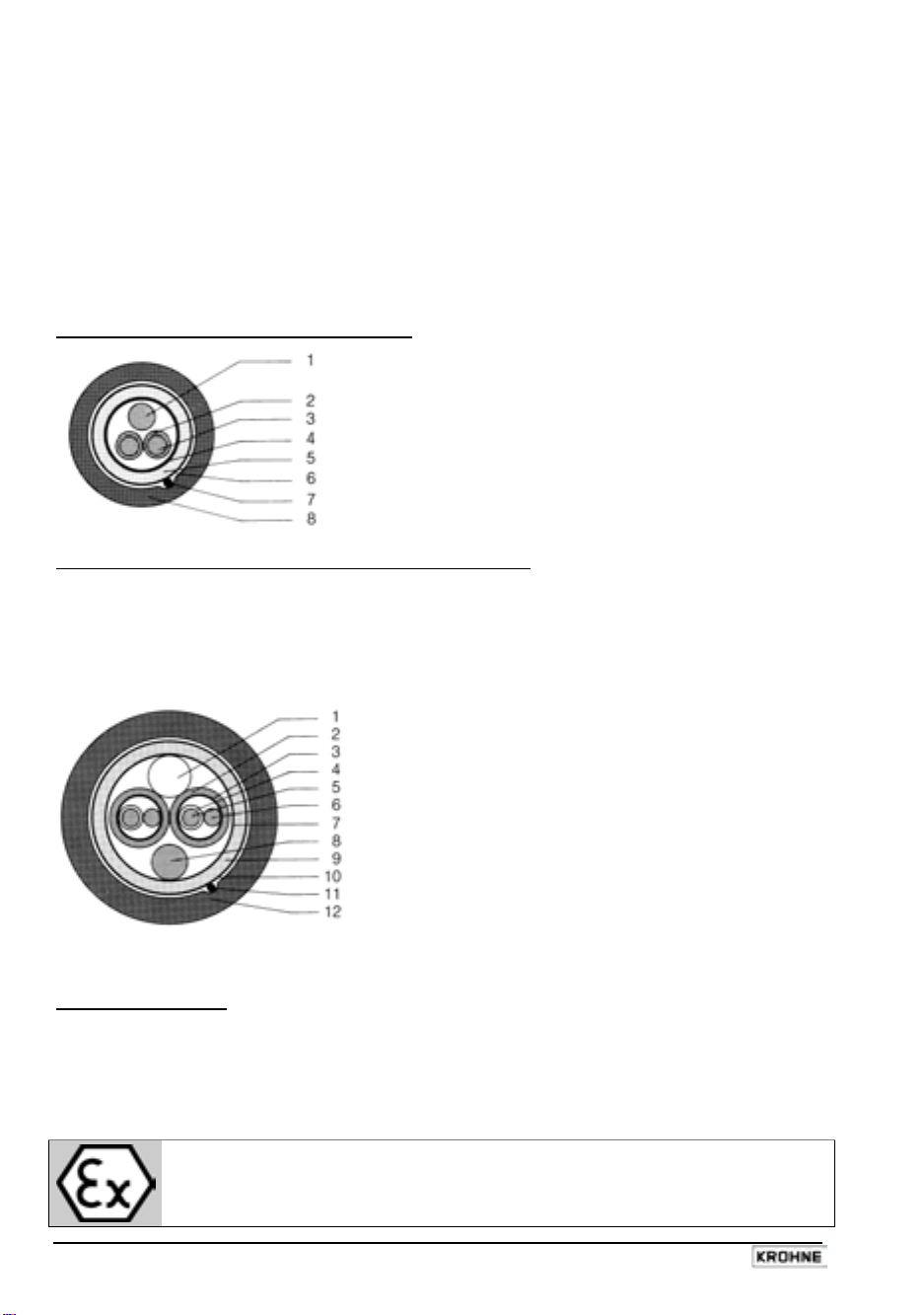
Signal line A (type DS) with double shielding
1 Stranded drain wire, 1st shield, 1.5 mm² or AWG 14
2 Insulation
3 Stranded wire 0.5 mm² or AWG 20 (3.1 red/3.2 white)
4 Special foil, 1st shield
5 Insulation
6 Mu-metal foil, 2nd shield
7 Stranded drain wire, 2nd shield, 0.5 mm² or AWG 20
Signal line B (type BTS) with triple shielding (bootstrap line)
8 Outer sheath
The bootstrap technology always controls the individual shields (3) of the signal converter exactly
to the voltage which is supplied to the signal conductors (5). As this prevents voltage differences
between the individual shields (3) and signal conductors (5), no current flows via the line
capacitances between 3 and 5. The line capacitance seems to become ”zero”.
This allows greater cable lengths in case the electric conductivity of the liquid to be measured is
low.
1
Dummy glider wire
2
Insulation (2.1 red/2.2 white)
3
Special foil, 1st shield (3.1/3.2)
4
Insulation (4.1/4.2)
5
Stranded wire 0.5 mm² or AWG 20
(5.1 red/5.2 white)
6
Stranded drain wire, 1st shield, 0.5 mm² or
AWG 20 (6.1/6.2)
7
Special foil, 2nd shield
8
Stranded drain wire, 2nd shield, 1.5 mm² or AWG 14
9
Insulation
10
Mu-metal foil, 3rd shield
11
Stranded drain wire, 3rd shield, 0.5 mm² or AWG 20
12
Outer sheath
Field current line C1
Line 2 x 0.75 mm² (18 AWG) Cu or 2 x (4 x) 1.5 mm² (14 AWG) Cu (Cu = copper cross section)
The cross section depends on the required cable length.
For max. permissible cable lengths please refer to Section 1.3.4
IMPORTANT!
For EEx versions, also pay regard to all directions included in Sect. 6.1 and 13.
Only the EEx flow sensor may be installed in the hazardous area. The EEx
certified signal converter must be installed outside the hazardous area!
6 IFC 110 F
05/2003
Page 7
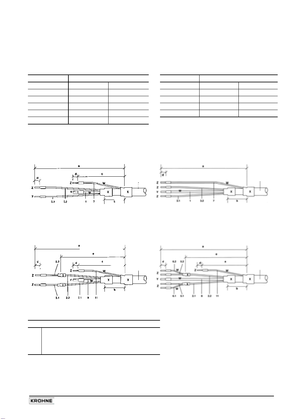
1.3.2 Stripping (preparation) of signal cables
Please note: The numbers in the drawings designate the stranded drain wires of signalling cables
A and B, see sectional drawings in Sect. 1.3.1.
Flow sensor Converter
Length flow sensor Length Converter
mm inch mm inch
a 90 3.60 a 50 2.00
b 8 0.30 b 8 0.40
c 25 1.00 d 8 0.40
d 8 0.30 e 20 0.80
e 70 2.80
Signal cable A (type DS),
double shielding
for flow sensor
Signal cable A (type DS),
double shielding
for IFC 110 F Converter
Signal cable A
bending radius
≥ 50 mm (≥ 2”)
Signal cable B (type BTS),
with triple shielding (bootstrap)
for flow sensor
Signal cable B
bending radius
≥ 50 mm (≥ 2”)
Customer-supplied materials
W
Insulation tubing (PVC), Ø 2.0-2.5 mm (Ø 1”)
X
Heat-shrinkable tubing or cable sleeve
Y
Wire end sleeve to DIN 41 228: E 1.5-8
Z
Wire end sleeve to DIN 41 228: E 0.5-8
Signal cable A
bending radius
≥ 50 mm (≥ 2”)
Signal cable B (type BTS),
with triple shielding (bootstrap)
for IFC 110 F Converter
Signal cable B
bending radius
≥ 50 mm (≥ 2”)
IFC 110 F 7
05/2003
Page 8
1.3.3 Grounding of flow sensor
• The flow sensor must be correctly connected to ground.
• The grounding cable may not transfer interference voltages.
• Do not use the grounding cable to connect more than one device to ground.
• In hazardous areas the grounding line is also used for potential equalizing purposes. Special
grounding instructions are contained in the installation instructions for hazardous-duty
instruments (only supplied together with such instruments).
• The flow sensor is connected to ground by means of a functional grounding conductor FE.
• Special grounding instructions for the connection of several flow sensors are contained in the
separate installation instructions of the flow sensors.
• These instructions also contain detailed descriptions on how to use grounding rings and how
to install flow sensors in metal or plastic pipes or in pipes which are coated on the inside.
Warning: Instrument must be properly grounded to avoid personnel shock hazard.
IMPORTANT!
For EEx versions, also pay regard to all directions included in Sect. 6.1 and 13.
Only the EEx flow sensor may be installed in the hazardous area. The EEx
certified signal converter must be installed outside the hazardous area!
8 IFC 110 F
05/2003
Page 9
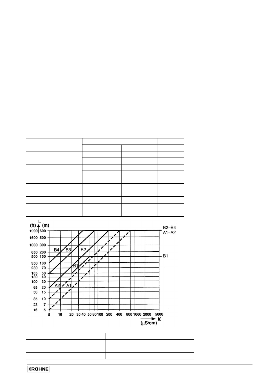
1.3.4 Cable lengths (max. distance between signal converter and flow sensor)
Abbreviations and explanations
The abbreviations used in the following tables, diagrams and connection diagrams stand for:
A Signal line A (type DS) with double shielding, max. length see diagram
B Signal line B (type BTS) with triple shielding, max. length see diagram
C Field current line, minimum cross section (A
) and max. length see table
F
D High-temperature silicone line, 3x1.5 mm² (14 AWG) Cu, with single shield,
max. length 5 m (16 ft)
E High-temperature silicone line, 2 x 1.5 mm² (14 AWG) Cu, max. length 5 m (16 ft)
Cross section of field current line C in Cu, see table
A
F
L Cable length in m or ft
Electrical conductivity of the process liquid
Κ
ZD Intermediate connection box required in connection with lines D and E for flow sensors
ALTOFLUX 4000 F, PROFIFLUX 5000 F and VARIFLUX 6000 F for process temperatures
exceeding 150°C (302°F).
Recommended length of signal line
for magnetic field frequencies ≤ 1/6 x power frequency
Flow Meter size Signal Please note!
sensor DN mm Inch line
VARIFLUX 6000 F 2.5 - 15 1/10 - 1/2 B1
25 - 80 1 - 3 A1 / B3
PROFIFLUX 5000 F 2.5 - 1/10 - B1
4 - 15 1/6 - 1/2 B2
For application with
empty pipe detection
(EPD) max. length
< 20 m / 66 ft.
25 - 100 1 - 4 A1 / B3
ALTOFLUX 4000 F 10 - 150 3/8 - 6 A1 / B3
200 - 1200 8 - 48 A2 / B4
ALTOFLUX 2000 F 150 - 250 6 - 10 A2 / B4
ECOFLUX 1000 F 10 - 150 3/8 - 6 A1 / B3
M900 10 - 300 3/8 - 12 A2 / B4
Max. length and minimum cross section of field current line
Length L Cross section AF (Cu), minimum
0 to 150 m 5 to 500 ft 2 x 0.75 mm² Cu 2 x 18 AWG
150 to 300 m 500 to 1000 ft 2 x 1.50 mm² Cu 2 x 14 AWG
300 to 600 m 1000 to 1900 ft 4 x 1.50 mm² Cu 4 x 14 AWG
05/2003
IFC 110 F 9
Page 10
1.3.5 Connection diagrams for power supply and flow sensors
Important remarks for circuit diagrams PLEASE NOTE !
• The figures in brackets indicate the stranded drain wires of the shields (see cross-sectional
drawings of signal lines in Section 1.3.1).
• Electrical connection to VDE 0100 ”Regulations for the erection of power installations with
nominal voltages up to 1000 V”
• Power supply 24 V AC / DC:
• Systems to be used in hazardous areas are subject to special regulations applying to
electrical connections (see Section 1.3.6) for hazardous-duty instruments.
• PE = protective conductor
Do not remove the internal connection (cable) inside the terminal compartment of the signal
converter (yellow/green wire) between the U-clamp terminal and terminal 10 (protective
*
conductor for protection class I instruments).
IMPORTANT!
Electrical connection of EEx flow sensors and EEx signal converters to be carried
out as described in Sect. 1.3.6.
protective extra-low voltages (PELV) acc. to VDE 0100/
VDE 0106 and/or IEC 364/IEC 365, or corresponding
national regulations.
FE = functional ground conductor
10 IFC 110 F
05/2003
Page 11
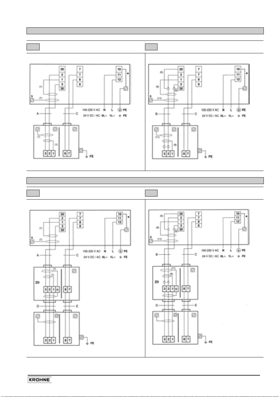
Process temperature below 150°C (302°F)
I Signal cable A (type DS) II Signal cable B (type BTS)
IFC 110 F V 2.0 IFC 110 F V 2.0
Flow sensor Flow sensor
III Signal cable A (type DS) IV Signal cable B (type BTS)
Process temperature above 150°C (302°F)
IFC 110 F V 2.0 IFC 110 F V 2.0
Flow sensor Flow sensor
IFC 110 F 11
05/2003
Page 12

1.3.6 EEx-Connection diagrams for power supply and flow sensors
PLEASE NOTE!
• The figures in brackets indicate the stranded drain wires for the shields (see cross-sectional
drawing of signal cable in Section 1.3.1).
• The connections for the intrinsically safe electrode circuit including the shield terminals
are safety-separated up to a peak value of 375 V from the terminals for thepower supply,
for the inputs/outputs and for the field circuit. They are galvanically isolated from the housing
(PE/PA).
• For connection of the intrinsically safe electrode circuit including shield terminals to the
primary head, please refer to Item 12 in EN 60079-14.
The non-intrinsically safe field circuit to be connected to the primary head in keeping with the
requirements of Item 9 in EN 60079-14 .
• The non-intrinsically safe input and output circuits may only be routed into the hazardous
area in compliance with appropriate measures as specified in EN 60079-14.
• Supply power (terminals 11,12)
In conformity with current regulations for electrical installations, an isolating facility is required
to be provided for the signal converter. The housing of the IFC 110 F – EEx signal converter
must be incorporated in the equipotential bonding system (via external PA connection).
Note!
A PE safety conductor is not connected if a functional extra-low voltage with safety
separation (PELV) is used. Grounding is then carried out by way of the equipotential
bonding conductor.
• Electrode circuit (terminals 1, 20, 2, 3, 30 and shield terminal S)
In conformity with the requirements for separation of intrinsically safe circuits, Category ib to
EN 50 020, the cable for the intrinsically safe electrode circuit must, up to the terminals, be
separated from all non-intrinsically safe circuits.
Terminals 20 and 30 are optionally provided for connecting cables with single shielding. The
terminal for the outer shield (S) is capacitance grounded in the signal converter. The outer
overall shield to be connected by the shortest possible wire to the shield terminal. Shields to
be carefully insulated from ground and from each other.
• Field circuit FSV (terminals 7, 8)
The field circuit is all-pole protected on the FSV circuit board with an internal fusible link
160mA / 250V.
• Input/output circuits
The connection is made to functional extra-low voltage circuits with safety separation (PELV).
The I/O functions and technical data are described in the Standard Installation and Operating
Instructions.
IMPORTANT!
For EEx versions, also pay regard to all directions included in Sect. 6.1 and 13.
Only the EEx flow sensor may be installed in the hazardous area. The EEx
certified signal converter must be installed outside the hazardous area!
Do not remove the internal connection (cable) inside the terminal compartment of the signal
converter (yellow/green wire) between the U-clamp terminal and terminal 10 (protective
*
conductor for protection class I instruments).
12 IFC 110 F
05/2003
Page 13
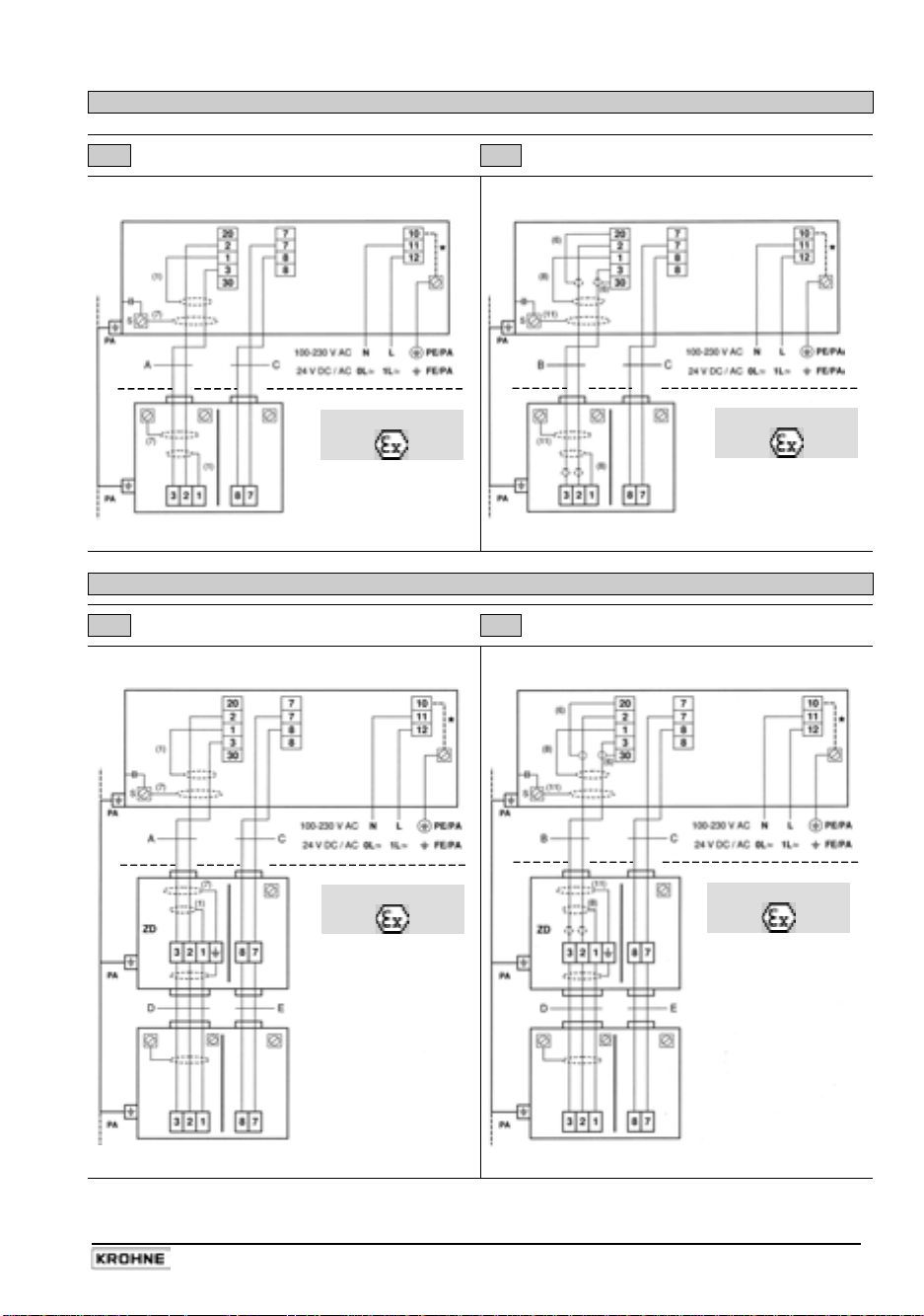
Process temperature below 150°C (302°F)
I Signal cable A (type DS) II Signal cable B (type BTS)
IFC 110 F V 2.0 IFC 110 F V 2.0
Hazardous area
Hazardous area
Flow sensor Flow sensor
III Signal cable A (type DS) IV Signal cable B (type BTS)
IFC 110 F V 2.0 IFC 110 F V 2.0
Process temperature above 150°C (302°F)
Hazardous area
Hazardous area
Flow sensor Flow sensor
IFC 110 F 13
05/2003
Page 14

2 Electrical connection: outputs and inputs
IMPORTANT!
For EEx versions, also pay regard to all directions included in Sect. 6.1 and 13.
Only the EEx flow sensor may be installed in the hazardous area. The EEx
certified signal converter must be installed outside the hazardous area!
2.1 Important information for outputs and inputs …….…………. PLEASE NOTE !
• The signal converter has the following outputs and inputs:
Output and Symbol Terminals Remarks
input group
Power output I IS / I active / passive selectable
Current output P P / P for electronic totalizers
Pulse output A1* (P2)
Status outputs A1* and A2
Status outputs D1 and D2
Control inputs C1 and C2
A1* / A⊥
A1* / A⊥ / A2 A⊥ common centre grounding contact
D1 / D⊥ / D2 D⊥ common centre grounding contact
C1 / C⊥ / C2 C⊥ common centre grounding contact
Internal power supply E E+ / E- for active mode of outputs and inputs
* Output A1 can be used as a 2nd pulse output P2 for electromechanical totalizers or as a
4th status output, see Section 4.4, Fct. 3.07 HARDWARE.
• The output and input groups are electrically isolated from each other and from all other input
and output circuits.
• Please note:
A⊥ common centre grounding contact for outputs A1 and A2
D⊥ common centre grounding contact for outputs D1 and D2
C⊥ common centre grounding contact for control inputs C1 and C2
• Active mode:
the signal converter supplies the power for the operation (selection) of
receiver instruments, observe max. operating data (terminals E+ and E-).
• Passive mode:
the operation (selection) of receiver instruments requires an external
power supply (U
), observe max. operating data.
ext
• Connection diagrams of outputs and inputs are shown in Section 2.6.
• For operating data of outputs and inputs please refer to Sections 2.6 and 10.1.
for electromechanical totalizers
14 IFC 110 F
05/2003
Page 15

2.2 Current output I
• The current output is electrically isolated from all other circuits.
• Setting data and functions can note down in the Table in Sect. 3.
Please also refer to Section 2.7 ”Standard factory settings”.
• All operating data and functions are adjustable (see Sections 4.4 and 5.6, Fct. 1.05).
• Max. load :
• Selfcheck :
- short-circuit of mA loop via test function, see Fct. 2.03
or when power supply is switched on in Fct. 3.07
Error message on display (see Fct. 1.04, Section 5.4) and/or
status output (see Fct. 1.07-1.10, Section 5.8).
• Current value for error identification is adjustable, see Fct. 1.05 and Section 5.6.
• Range change-over, automatically or externally by control input,
see Sections 4.4 and 5.19, Fct. 1.07-1.10 and 1.11-12.
Setting range from 5-80% of Q
(corresponding low to high range ratio from 1:20 to 1:1.25).
Change-over from high to low range at approx. 85% of low range and vice versa at approx.
98% of low range.
The active range is signalled via one of the four status outputs.
• Forward/reverse flow measurement (F/R mode) is possible (see Section 5.15).
• Connection diagrams see Section 2.6.
active operation 15-500 Ω
passive operation
≤ 800 Ω
- interrupting the mA loop, and
100%
IFC 110 F 15
05/2003
Page 16
2.3 Pulse outputs P and A1
2.3.1 Pulse output P for electronic totalizers (EC)
• Pulse output P is electrically isolated from all other circuits.
• Setting data and functions can note down in the Table in Sect. 3.
Please also refer to Section 2.7 ”Standard factory settings”.
• All operating data and functions are adjustable, see Sections 4.4 and 5.7, Fct. 1.05.
• Active mode:
Passive mode:
• Max. adjustable frequency 10 kHz
• Scaling
in pulses per unit volume
• Pulse width
automatic
pulse duty factor approx. 1:1 at Q
pulse width range from 0.01 to 1 s
correspondingly lower output frequency.
• Forward/reverse flow measurement (F/R mode) is possible, see Section 5.15.
• Connection diagrams see Section 2.6
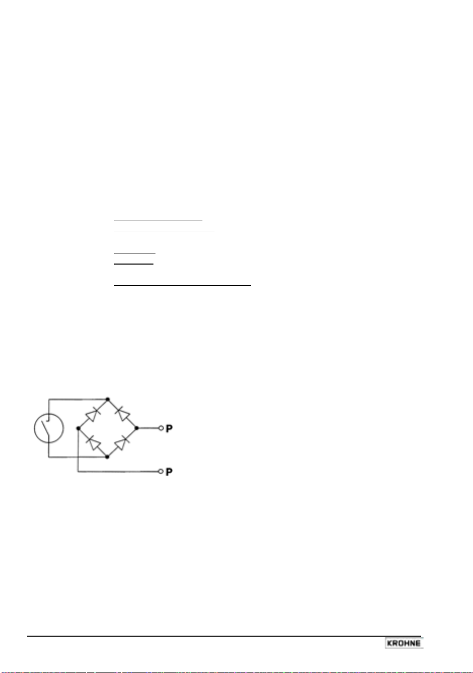
• Schematic wiring diagram for pulse output P for electronic totalizers EC
Similar to a relay contact, this pulse output switches direct and alternating voltages.
uses the internal power supply, terminals E+/Erequires external power supply, U
in pulses per unit time
(e.g. 1000 pulses/s at Q
≤ 32V DC/24V AC, I ≤ 30mA
ext
(e.g. 100 pulses/m³ or US Gal).
symmetric
, pulse duty factor 1:1, independent of output frequency,
, with optimum pulse width,
, or
100%
adjustable as required for
100%
flow) or
16 IFC 110 F
05/2003
Page 17

2.3.2 Pulse output A1 for electromechanical totalizers (EMC)
PLEASE NOTE:
The output terminal A1 can be used as status output A1 or as a 2nd pulse output A1 for
electromechanical totalizers.
Setting is as described in Fct. 3.07 HARDWARE, see Sections 4.4 and 5.18.
• Pulse output A1 is electrically connected to status output A2 (common centre grounding
contact A⊥) but electrically isolated from all other circuits.
• Setting data and functions can note down in the Table in Sect. 3.
Please also refer to Section 2.7 ”Standard factory settings”.
• All operating data and functions are adjustable, see Sections 4.4 and 5.7, Fct. 1.07.
• Active mode:
• Passive mode:
uses the internal power supply, terminals E+/Erequires external power supply, U
≤ 32V DC/24V AC, I ≤ 100mA
ext
(I ≤ 200mA for polarized DC operation, see Section 6.3)
• Max. adjustable frequency 50 kHz
• Scaling
in pulses per unit of time
(e.g. 10 pulses/s at Q
100%
flow) or
in pulses per unit of volume (e.g. 10 pulses/m³ or US Gal).
• Pulse width
symmetric
, pulse duty factor 1:1, independent of output frequency,
automatic, with optimum pulse width,
pulse duty factor approx. 1:1 at Q
pulse width range from 0.01 to 1 s
, or
100%
adjustable as required for
correspondingly lower output frequency.
• Forward/reverse flow measurement (F/R mode) is possible, see Section 5.15.
• Connection diagrams see Section 2.6
• Schematic wiring diagram for pulse output A1 for electromechanical totalizers EMC.
This pulse output has a MOSFET switch as output which switches direct and alternating
voltages similar to a relay contact.
IFC 110 F 17
05/2003
Page 18

2.4 Status outputs A1 / A2 / D1 / D2
PLEASE NOTE:
The output terminal A1 can be used as status output A1 or as a 2nd pulse output A1 for
electromechanical totalizers.
Setting is as described in Fct. 3.07 HARDWARE, see Sections 4.4 and 5.18.
• Status outputs A1/A2 and D1/D2 with the common centre grounding contacts A⊥ and B⊥ are
electrically isolated from each other and from all other circuits.
• Setting data and functions can note down in the Table in Sect. 3.
Please also refer to Section 2.7 ”Standard factory settings”.
• All operating data and functions are adjustable, see Sections 4.4 and 5.8, Fct. 1.07-1.10.
• Active mode:
Passive mode:
uses the internal power supply, terminals E+/Erequires external power supply, U
≤ 32V DC/24V AC, I ≤ 100mA
ext
(I ≤ 200mA for A1 in case of polarized DC operation, see Section 6.3)
• The following operating conditions can be signalled using the status outputs:
- flow direction (F/R mode)
- limits
- error messages
- active range in case of range change-over
- inverse operation of A1 and A2 or D1 and D2,
i.e. used as change-over switch with common centre grounding contact A⊥ or D⊥.
• Connection diagrams see Section 2.6
• Schematic wiring diagram for status outputs A1/A2 and D1/D2.
This status outputs have MOSFET switches as outputs which switch direct and alternating
voltages similar to relay contacts.
2.5 Control inputs C1 and C2
• Control inputs C1 and C2 are electrically connected (common centre grounding
contact C⊥) but electrically isolated from all other circuits.
• Setting data and functions can note down in the Table in Sect. 3.
Please also refer to Section 2.7 ”Standard factory settings”.
• All operating data and functions are adjustable, see Sections 4.4 and 5.9, Fct. 1.11-1.12.
• Active mode:
Passive mode:
uses the internal power supply, terminals E+/Erequires external power supply, U
≤ 32V DC/24V AC, I ≤ 10mA
ext
• The following operating conditions can be initiated using the control inputs:
- external range change
- holding of output values
- zeroing the outputs
- resetting the internal totalizer
- resetting (deleting) the error messages
• Connection diagrams see Section 2.6
18 IFC 110 F
05/2003
Page 19

2.6 Connection diagrams of outputs and inputs
IMPORTANT!
For EEx versions, also pay regard to all directions included in Sect. 6.1 and 13.
Only the EEx flow sensor may be installed in the hazardous area. The EEx
certified signal converter must be installed outside the hazardous area!
I
P, A1*
A1*, A2,
D1, D2
C1, C2
Current output (included HART
Pulse output
Status outputs
Control inputs
Totalizer
-electromechanical (EMC)
- electronic (EC)
milliampmeter
0-20 mA or 4-20 mA and other
Key, N/O contact
External voltage source (U
connection polarity arbitrary
DC voltage,
external power source (U
Active mode: the IFC 110 F supplies the power required for operating (driving) the receiver
instruments. Observe the max. operating data (terminals E+ and E-).
Passive mode: an external power supply source (Uext) is required for operating (driving) the
receiver instruments.
Groups A / C / D / E / I / P are electrically isolated from each other and from all other input and
output circuits.
Please note:
common reference potential
A⊥ for A1 and A2
C⊥ for C1 and C2
D⊥ for D1 and D2
®
)
), DC or AC voltage,
ext
), note connection polarity
ext
Please note ! Unwired
contacts or terminals may not
have any conductive
connection with other
electrically conducting parts.
Interface operation with
HART® or RS 485 (Option)
see Sect. 6.4.
*
selectable as
status output A1 or
pulse output A1
IFC 110 F 19
05/2003
Page 20

Current output I
{
active
Current output I
|
range change BA
with automatic
active
without external change-over relay
low range
high range
Ri 15 - 500 Ω
Ri 15 - 500 Ω
Current output I
}
(see Sect. 6.8 passive/active for pulse and current outputs (P and I
passive
Forward/reverse flow meausrement (F/R mode)
~
active
)
operation without external change-over relay
reverse
flow
forward
flow
reverse
flow
forward
flow
Ri 15 - 500 Ω
selectable with internal power supply
E or external power supply U
the connection diagrams for pulse output P on the
ext.
Electronic totalizers must be connected as shown in
following page.
U
15 - 22 V DC 22 - 32 V DC
ext.
R
0 - 500 Ω 0 - 800 Ω
i
Pulse output A1 active
Pulse output A1 passive
for electromechanical totalizers (EMC) for electromechanical totalizers (EMC)
≤ 32 V DC / ≤ 24 V AC I ≤ 10 mA
Ri ≥ 160 Ω
I ≤ 100 mA
20 IFC 110 F
U
ext.
oder umschaltbar auf
≤ 32 V DC I ≤ 200 mA
U
ext.2
05/2003
Page 21

Pulse output P
active
for electronic totalizers (EC)
for frequencies ≤ 1 kHz
Pulse output P
active
for electronic totalizers (EC)
for frequencies > 1 kHz
R1 = 1 kΩ/0.5 W I ≤ 20 mA R
> 100 kΩ R = 1 kΩ/0.35 W I ≤ 30 mA
i EC
R2 / 0.2 W
U
EC max
10 kΩ 1 kΩ 270 Ω
22 V 12 V 5 V
Pulse output P
passive
for electronic totalizers (EC)
for frequencies ≤ 1 kHz
U
≤ ≤ 32 V DC / ≤ 24 V AC
ext
I
≤ ≤ 30 mA
R
=
1 - 10 kΩ
P
≥
R
2
U
ext
R
for frequences > 1 kHz
U
=
ext
R
i EC
I ~ 30 mA ~ 18 mA
R
P
R
U
EC
≤ 24 V DC / AC
≥ 100 kΩ
560 Ω 1 kΩ
0.5 W 0.35 W
16 V 18 V
* Shielded cables
must be used to prevent radio interference at pulse output frequencies > 100 Hz
IFC 110 F 21
05/2003
Page 22

Status outputs D1 / D2 / A1 / A2 active
I ≤ 100 mA
e.g. message display
9
Control inputs C1 / C2 active
Status outputs D1 / D2 / A1 / A2 passive
≤ 32 V DC / ≤ 24 V AC
U
ext.
I ≤ 100 mA
9
e.g. message display
Control inputs C1 / C2 passive
Contacts 24 V, 10 mA
I ≤ 7 mA I ≤ 10 mA
22 IFC 110 F
≤ 32 V DC / ≤ 24 V AC
U
ext.
05/2003
Page 23

3 Start-up
• Before connecting to power, check that the instrument is correctly installed as described in
Sections 1 and 2.
• The flowmeter, flow sensor and signal converter are delivered ready for operation. All
operating data are set at the factory in accordance with your specifications.
Please also refer to Section 2.7 ”Standard factory settings”.
• Switch on the power supply. The flowmeter immediately begins to measure the flow.
• When the power supply is switched on, the display successively shows START UP and
READY. Then the current flow rate and/or the current totalizer count are displayed. Displays
are either steady or cyclic depending on the setting described for Fct. 1.04.
• 2 light-emitting diodes (LED) in the ”diagnostics” field on the front panel of the signal
converter indicate the status of measurement.
LED displays Status of measurement
Green ”normal” LED Everything O.K.
is flashing
Green ”normal” LED Momentary overload of outputs and/or A/D converter.
and red ”error” LED Detailed error messages by setting Fct. 1.04 DISPLAY,
are flashing alternately subfunction ”MESSAGES” to ”YES”, see Sections 4.4 and 5.5.
Red ”error” LED is Fatal Error, see Sections 7.3 and 7.4
flashing
IMPORTANT!
For EEx versions, also pay regard to all directions included in Sect. 6.1 and 13.
Only the EEx flow sensor may be installed in the hazardous area. The EEx
certified signal converter must be installed outside the hazardous area!
IFC 110 F 23
05/2003
Page 24

4 Operating of the signal converter
4.1 KROHNE operating concept
24 IFC 110 F
05/2003
Page 25

4.2 Operating and control elements
The instrument can be operated
by means of ....
…
the 15 keys ~
after removal of the glass cover,
…
the 3 magnetic sensors
bar magnet without opening the
housing (optional).
Display, 1st line Displaying numerical data
{
Display, 2nd line Displaying units and texts
|
Display, 3rd line 6 arrows to mark the current display
}
flow rate current flow rate
+
totalizer
-
control in
~
5 keys for operating the signal converter ← → ↵ ↑ ↓
10 keys for direct numerical setting of function values (not function numbers)
Compass field showing that a key is pressed
magnet active
green
red
3 magnetic sensors (optional), operated by bar magnet without opening the housing,
function of the sensors as described for the three keys → ↵ ↑, see
diagnostics
normal
error
IMoCom
supplementary equipment, see Section 6.4, slide window to the left
totalizer
totalizer
sum totalizer (+ and -)
Σ
1/2
control input 1 or 2 active
LED green/red, magnetic sensors active
= built-in magnetic sensors (optional), see
= operation of one of the 3 magnetic sensors
2 LEDs signalling the status of measurement
green LED
red LED
IMoCom bus, multipoint connector for connecting external
= correct measurement, everything O.K.
= error, parameter or hardware error
and accessible
.
~
and the
IFC 110 F 25
05/2003
Page 26

4.3 Key functions
In the following, the cursor or flashing part of the display is shown against a grey background.
To start operator control
Measuring mode
1 3 . 5 7 1
m 3 / h
PLEASE NOTE: if ”YES” is selected in Fct. 3.04 ENTRY CODE, ”CodE 1 - - - - - - - - -”
appears in the display after pressing the → key.
Enter the password for the entry code which is a sequence of 9 keys: → → → ↵ ↵ ↵ ↑ ↑ ↑
(each keystroke confirmed by ” * ”).
To terminate operator control
Press key ↵ any number of times until one of the following menus
Fct. 1.0 OPERATION, Fct. 2.0 TEST or Fct. 3.0 INSTALL is displayed.
F c t . 3. 0
I N S T A L L.
Store new parameters: acknowledge by
New parameters not to be stored:
Keyboard with 10 keys
The keyboard with the 10 keys (0-9) is used for setting all flashing numbers (cursor).
Exception: the digits of the function numbers, such as Fct. 1.03, can only be changed with
keys ↑ or ↓.
→
Press key ↵
↵
Operator control mode
F c t . 1. 0
O P E R A T I O N
S T O R E Y E S
pressing key ↵. Measuring mode is
continued with new parameters.
press key ↑ to display
”STORE NO”.
Measuring mode is continued with the ”old”
parameters after pressing key ↵.
26 IFC 110 F
05/2003
Page 27

To change numbers
3 9 7. 3 5
m 3 / h
increase number
decrease number
3 9 7. 4 5
↑
m 3 / h
↓
To shift cursor (flashing position)
3 9 7. 3 5
m 3 / h
shift to right
→
shift to left
3 9 7. 3 5
m 3 / h
←
To alter texts (units)
In case of units, the numerical
value is converted automatically.
3. 7 6 9 9
L i t e r / S e c
select next text
select preceding text
9 3. 3 6 5
↑
U S. G a l / m i n
↓
To change from text (unit) to numerical setting
1 3. 5 7 1
m 3 / h
change to numerical setting
1 3. 5 7 1
→
return to text setting
m 3 / h
←
To change to subfunction
Subfunctions have no “Fct. No.” and are identified by a “→”
2 D I R.
↵
→
R A N G E I
To revert to function display
10. 3
S e c
F c t. 1. 0 2
↵
T I M E C O N S T.
IFC 110 F 27
05/2003
Page 28

4.4 Table of settable functions
Abbreviations used:
A1, A2
Status outputs
(A1 can also be 2nd pulse output A1)
C1, C2
Control inputs
D1, D2
Status outputs
DN
Meter size, nominal size
F
= ½ x pulse width (s) for ≤ 50 Hz
max
≤ 10 kHz if ”AUTO” or ”SYM.” are selected in
subfunction ”PULSWIDTH”
F
= 10 pulses/h
min
FM
Conversion factor volume
see Fct. 3.05 ”FACT. VOL.”
F
Conversion factor time
T
see Fct. 3.05 ”FACT. TIME”
GK
Flow sensor constant
I
Current output
I
Current at 0% flow rate
0%
I
Current at 100% flow rate
100%
Fct. Text Description and setting
1.0 OPERATION Operating menu
FULL SCALE Full-scale range for flow rate Q
Selection of unit
Setting ranges
The range depends on the nominal width (DN) and the
flow velocity (v): Q
Nominal width/meter size vmin = 0.3 m/s (1 ft/s) vmax = 12 m/s (40 ft/s)
● DN 2.5–1200 / 1/10”–48”: 0.0053 – 48 860 m³/h
0.0237 – 218 560 US.Gal/min
● DN 1300–3000 / 52”–120” 1435 – 305 360 m³/h
(see Section 8.6) 6415 – 1 366 000 US.Gal/min
VALUE P
→
and/or
VALUE P2
→
been exceeded or would not have been reached.
1.02 TIMECONST. Time constant
Selection: ● ALL (applies to display and all outputs)
● ONLY I (only display, current and status outputs)
Range: ● 0.2 – 99.9 Sec
1.03 L.F. CUTOFF Low-flow cutoff (L.F. CUTOFF)
● OFF (fixed tripping points: ON = 0.1% / OFF = 0.2%)
● PERCENT (variable tripping points) ON OFF
1 – 19% 2 – 20%
Note: the cutoff ”OFF” value must be greater than the cutoff ”ON” value.
P (P2)
Pulse output (2nd pulse output A1)
P
= F
max
P
min
Q
Q
100%
Q
max
for any unit,
for any unit,
Q
min
SMU
v
v
max
v
min
F/R
m³/h
•
user unit, factory setting ”Liter/h” or ”US MGal/day” (see Fct. 3.05)
•
•
max/Q100%
= F
min/Q100%
Current flow rate
100% flow rate = full-scale range
π
= /4 DN² x v
4
Q
100%
π
= /4 DN² x v
4
Q
100%
Low-flow cutoff for I and P
Flow velocity
Maximum flow velocity (12 m/s or 40 ft/s) at Q
Minimum flow velocity (0.3 m/s or 1 ft/s) at Q
Forward/reverse flow in F/R measuring mode
100%
Liter/Sec
Press → key to change to numerical setting
π
= DN² x v
min
4
Press ↵ key to return to Fct. 1.01 FULL SCALE
Pulse value for pulse output P (Fct. 1.06 ”VALUE P”) and/or
for the 2nd pulse output A1 (Fct. 1.07 ”VALUE P2”) has been changed.
With the ”old” pulse values the output frequency (F) would have
/ Q
P
= F
min
min
100%
P
max
= F
max
/ Q
100%
Press ↵ key to change to numerical setting.
Press ↵ key to return to Fct. 1.02 TIMECONST.
Press → key to change to numerical setting.
Press ↵ key to return to Fct. 1.03 L.F. CUTOFF.
(= max. full-scale range
max
at v
= 12 m/s or 40 ft/s)
max
(= min. full-scale range
min
at v
= 0.3 m/s or 1 ft/s)
min
US.Gal/min
•
Q
min
= DN² x v
max
Check new values!
π
4
max
100%
100%
28 IFC 110 F
05/2003
Page 29

Fct. Text Description and setting
1.04 DISPLAY Display functions
→ DISP.FLOW
● NO DISP. ● User unit, factory setting ”Liter/h” or ”US MGal/day” (s. Sect. 3.05)
● m³/h ● PERCENT
● Liter/Sec ● BARGRAPH (value and bar graph display in %)
● US.Gal/min
● NO DISP. (totalizer is ON but no display)
● OFF (totalizer is OFF)
● + TOTAL. ● - TOTAL. ● +/- TOTAL.
● ALL (display single counts or all)
● m³ ● Liter ● US.Gal
● User unit, factory setting ”Liter” (s. Sect. 3.05)
Format setting
● Auto (exponent notation)
● # . ####### ● ##### . ###
● ## . ###### ● ###### . ##
● ### . ##### ● ####### . #
● #### . #### ● ########
● NO ● YES (cyclic change with display of measured values)
1.05 CURRENT I Current output I
● OFF (switched off)
● + DIR. ● - DIR. (measurement in one flow direction only)
● 2 DIR. (forward/reverse flow, F/R mode)
press this key to change to subfunction ”REV. RANGE”.
(only displayed when ”2 DIR.” is selected)
● 100 PCT. (same as forward flow Q
● PERCENT setting range: 005 - 150 % of Q
(different value for reverse flow)
● 0 - 20 mA ● 4 - 20 mA (fixed ranges)
● mA (user-defined range) I0% - I
(Value I0% < I
● 22 mA
1.06 PULS P Pulse output P
Description of function of pulse output P on the next page.
1.07 STATUS A1 Status output A1 A1 = terminal
PULS2 A1 2nd pulse output A1
Description of function of status output A1 or 2nd pulse output A1
DISP.TOTAL.
→
DISP.MSG.
→
FUNCT. I
→
REV.RANGE
→
RANGE I
→
I ERROR
→
or
Selection of flow display
Press ↵ key to change to subfunction ”DISP. TOTAL.”
Selection of totalizer display
● SUM (Σ)
Press ↵ key to change to setting of display unit.
Press → key to transfer to format setting.
Press ↵ key to change to subfunction ”DISP. MSG.”
Additional messages desired during measuring mode?
Press ↵ key to return to Fct. 1.04 DISPLAY.
Selecting the current output I function
Press ↵ key to change to subfunction ”RANGE I”; if ”2 DIR.” is selected
Setting the full-scale range for reverse flow of Q
, see Sect. 1.01)
100%
100%
Press → key to change to numerical setting.
Press ↵ key to change to subfunction ”RANGE I”
Selecting the measuring range
!) 0 - 16 mA 4 - 20 mA
Press → key to change to numerical setting!
Press ↵ key to change to subfunction ”I ERROR”.
Selecting the error value
Press → key to change to numerical setting.
Press ↵ key to return to Fct. 1.05 ”CURRENT OUTPUT I”.
connected as status or pulse output (P2)
on the next page.
100%
● 0.0 to I
}
mA (variable when I0% ≥ 1 mA, see above)
0%
s. Fct. 3.07 HARDWARE, ”Terminal A1”
100%
100%
IFC 110 F 29
05/2003
Page 30

Fct. Text Description and setting
1.08 STATUS A2 Status outputs A2, D1 and D2
1.09 STATUS D1 Description of function of status outputs A2, D1 and D2
1.10 STATUS D2
1.11 CONTROL C1 Countrol inputs C1 and C2
1.12 CONTROL C2
1.06 PULS P Pulse output P for electronic totalizers up to 10,000 pulses/s
1.07 PULS2 A1 2nd pulse output A1 for electromechanical totalizers up to max. 50 Hz.
Connection of terminal A1 as a 2nd pulse output A1 or as status output A1,
FUNCT. P
→
FUNCT. P2
→
● + DIR. ● - DIR. (measuring in one flow direction only)
● 2 DIR. (forward/reverse flow, F/R mode)
SELECT P
→
SELECT P2
→
● PULSE/TIME (pulses per unit time for 100% flow rate)
PULSWIDTH
→
PULSWIDTH
→
● AUTO (automatic = 50% of cycle duration of 100% output frequency)
● SYM (symmetric = pulse duty factor approx. 1:1 across the entire range)
VALUE P
→
VALUE P2
→
● xxxx PulS/m³ ● xxxx PulS/Liter ● xxxx PulS/US.Gal
● xxxx PulS/user unit, factory setting ”Liter” or ”US MGal” (s. Fct. 3.05)
Setting range ”xxxx” depends on pulse width and full-scale range:
P
accordance with the same setting mode.
VALUE P
→
VALUE P2
→
● xxxx PulSe/Sec (=Hz) ● xxxx PulSe/min ● xxxx PulSe/h
Fct. 1.06 and 1.07 have identical menus and are configured in
● xxxx PulSe/user unit, factory setting ”h” (s. Fct. 3.05)
Setting range ”xxxx” depends on pulse width (see above).
}
on the next page but one.
}
Description of function of control inputs on the next page but one.
see Fct. 3.07 HARDWARE, ”Terminal A1”.
Selecting the function for pulse outputs P and P2
● OFF
Press ↵ key to change to subfunction ”SELECT P or P2”.
Selecting the type of pulse
● PULSE/VOL. (pulses per unit volume, flow rate)
Press ↵ key to change to subfunction ”PULSWIDTH”.
Selecting the pulse width
● 0.01 - 1.00 s (only for F
Press ↵ key to change to subfunction ”VALUE P or P2”.
Setting the pulse value per unit volume (only displayed when
”PULSE/VOL.” is selected in ”SELECT P or P2”
= F
/ Q
100%
, P
min
min
Press ↵ key to return to Fct. 1.06 PULS P or Fct. 1.07 PULS2 A1.
Setting the pulse value per unit time (only displayed when
”PULSE/TIME” is selected in ”SELECT P or P2”
Press ↵ key to return to Fct. 1.06 PULS P or Fct. 1.07 PULS2 A1.
< 50 pulses/s)
max
= F
max
max
/ Q
100%
above).
above).
30 IFC 110 F
05/2003
Page 31

Fct. Text Description and setting
1.07 STATUS A1 Status output A1 (terminal A1 connected as status output A1 or
1.08 STATUS A2 Status output A2
1.09 STATUS D1 Status output D1
1.10 STATUS D2 Status output D2
● INVERS D1 (inverse mode of D1 and D2)
● INVERS A1 (inverse mode of A1 and A2 possible only if A1
is operated as status output, see Fct. 3.07 HARDWARE, ”terminal A1”)
● SIGN I, P or P2
(F/R mode)
● OVERFL. I, P or P2
(overloading the outputs)
● EMPTY PIPE (”tube empty” signal only with built-in option)
● TRIP. POINT
Selection: ● + DIR. ● - DIR. ● 2 DIR.
Setting range: 000 - 150 PERCENT
● AUTO. RNG. Setting range: 05-80 PERCENT (= lower to upper range ratio
1:20 to 1:1.25, value must be higher than that of Fct. 1.03 L.F. CUTOFF)
Fct. Text Description and setting
1.11 CONTROL C1 Control input C1 and C2
1.12 CONTROL C2 ● OFF ● EXT. RNG. (external range change)
● OUTP. HOLD (hold output values)
● OUTP. ZERO (set outputs to ”min. values”)
● TOTAL.RESET (reset the totalizer)
● ERROR.RESET (delete error messages)
Fct. Text Description and setting
2.0 TEST Test menu
TEST Q Test measuring range Q
Precautionary query
● SURE NO
● SURE YES
of set full-scale range Q
Displayed value is available at outputs I and P.
2.02 HARDW. INFO Hardware information and error status
Before consulting factory, please note down all 6 codes.
Y Y Y Y Y Y Y Y Y Y
Y Y Y Y Y Y Y Y Y Y
Y Y Y Y Y Y Y Y Y Y Fct. 2.02 “HARDW. INFO“.
2.03 HARDW. TEST Hardware test (Precautionary query)
- SURE NO
- SURE YES
display next error. List of errors see Section 4.5.
→
Fct. 1.07 to 1.10 are configured in
accordance with the same setting
mode. Functions set for one of the
→
→ MODUL ADC
→ MODUL IO
→ MODUL DISP.
as a 2nd pulse output A1, see Fct. 3.07 HARDWARE, ”terminal A1”)
● OFF ● ON ● ALL ERROR ● FATAL.ERROR
dynamic behaviour
of outputs see Fct. 1.02
TIMECONST.:
}
I = ONLY I
P or P2 = ALL
Press → key to change to character.
Press ↵ key to change to numerical setting.
status outputs are no longer available
for the other status outputs.
Press ↵ key to change to numerical setting.
Press ↵ key to return to Fct. 1.06, 1.07, 1.08 or 1.09.
Setting range: 05-80 PERCENT (= lower to upper range ratio 1:20 to 1:1.25,
value must be higher than that of Fct. 1.03 L.F. CUTOFF)
Press ↵ key to change to numerical setting.
Press ↵ key to return to Fct. 1.11 or 1.12 CONTROL C1 or C2
Press ↵ key to return to Fct. 2.01 “TEST Q”.
Press ↵ key, then use ↑ key to
select value:
Press ↵ key to return to Fct. 2.01 “TEST Q”.
X . X X X X X . X X
X . X X X X X . X X
X . X X X X X . X X
If errors are found, the first one is displayed. Press ↓ key to
Press ↵ key to return to Fct. 2.03 ”HARDW. TEST”.
-110 / -100 / -50 / -10 / 0 / +10 / +50 / +100 / +110 PCT.
Press ↵ key to transfer to “MODUL IO“.
Press ↵ key to transfer to “MODUL DISP.“.
Press ↵ key to return to
Press ↵ key to return to Fct. 2.03 ”HARDW. TEST”.
Press ↵ key to start test, duration approx. 60 s
100%
.
IFC 110 F 31
05/2003
Page 32

Fct. Text Description and setting
3.0 INSTALL. Installation menu
3.01 LANGUAGE Select language for display texts
● GB / USA (English) ● S (Swedish)
● D (German) ● other languages on request
● F (French)
Press ↵ key to return to Fct. 3.01 “LANGUAGE”.
3.02 FLOWMETER Set data for flow sensor
DIAMETER
→
Select size from meter size table
● DN 2.5 - 1200 mm equivalent to 1/10 - 48 inch
● DN 1300 - 3000 mm equivalent to 52 - 120 inch (see Sect. 8.6)
FULL SCALE
→
Select with ↑ key.
Press ↵ key to change to subfunction “FULL SCALE”.
Full-scale range for flow Q
100%
To set, refer to Fct. 1.01 “FULL SCALE”.
VALUE P
→
and/or
VALUE P
→
Press ↵ key to change to subfunction “GK VALUE”.
Pulse value for pulse output P (Fct. 1.06 ”VALUE P”) and/or
for the 2nd pulse output A1 (Fct. 1.07 ”VALUE P2”) has been changed.
With the ”old” pulse values the output frequency (F) would have been exceeded
or would not have been reached.
GK VALUE
→
= F
/ Q
P
min
min
100%
P
max
Set primary constant GK
= F
max
/ Q
Check new value.
100%
See instrument nameplate of flow sensor.
Range: ● 1.0000 - 15.000
FIELD FREQ.
→
Press
key to change to subfunction “FIELD. FREQ.”.
↵
Magnetic field frequency
Values: 1/2, 1/6, 1/18 and 1/36 of power frequency, see instr. nameplate.
Press ↵ key to change to subfunction “FLOW DIR.”;
on DC instruments change to subfunction “LINE FREQ.”.
LINE FREQ.
→
Power frequency customary in the country where the instrument is used
Please note: this function is limited to instruments with DC supply unit (24 V DC)
to suppress line frequency interferences.
Values: 50 Hz and 60 Hz
FLOW DIR.
→
Press ↵ key change to subfunction “FLOW DIR.”.
Define flow direction (in F/R mode: forward flow).
Set according to direction of arrow on flow sensor:
● + DIR.
Press ↵ key to return to Fct. 3.02 “FLOWMETER”.
● – DIR. Select using ↑ key.
3.03 ZERO SET Zero calibration
Note: carry out only at ”0” flow and with completely filled measuring tube!
Precautionary query
● CALIB. NO
● CALIB. YES
Press ↵ key to return to Fct. 3.3 “ZERO SET”.
Press ↵ key to start calibration.
Duration approx. 15-90 s (depending on magnetic field
frequency), current flow rate displayed in the selected unit
(s. Fct. 1.04 ”DISP. FLOW”).
A ”WARNING” sign appears when flow rate ”>0”;
acknowledge by pressing ↵ key.
● STORE NO (do not store new zero value)
● STORE YES (store new zero value)
Press ↵ key to return to Fct. 3.03 “ZERO SET”.
3.04 ENTRY CODE Entry code required to enter setting mode?
● NO
● YES
Press ↵ to return to Fct. 3.04 “ENTRY CODE”.
(= entry with → only)
(= entry with → and Code 1:
→ → → ↵ ↵ ↵ ↑ ↑ ↑
)
32 IFC 110 F
05/2003
Page 33

Fct. Text Description and setting
3.05 USER UNIT Set any required unit for flowrate and counting
→ TEXT VOL.
Set text for required flowrate unit (max. 5 characters)
Factory setting = Liter or US MGal
Characters which can be assigned to each place:
● A-Z, a-z, 0-9, or “ – “ (= blank character).
FACT. VOL.
→
Press ↵ key to transfer to subfunction “FACT. VOL.”
Set conversion factor (F
) for volume
M
Factory setting ”1.00000 E+3” for ”Liter” or ”2.64172E-4” for ”US MGal”
(exponent notation, here 10³ or 2.64172 x 10⁻⁴)
Factor FM = volume per 1m³.
Setting range
● 1.00000 E-9 to 9.99999 E+9 (= 10-9 to 10+9)
TEXT TIME
→
Press ↵ key to transfer to subfunction “TEXT TIME”.
Set text for any time (max. 3 characters)
Factory setting = ”h” (hours)
Characters which can be assigned to each space:
● A-Z, a-z, 0-9, or “ – “ (= blank character).
FACT. TIME
→
Press ↵ key to transfer to subfunction “FACT. TIME”
Set conversion factor (F
) for time
T
Factory setting ”3.60000 E+3” for ”h” (exponent notation, here 3.3 x 10³).
Set factor FT in seconds.
Setting range
● 1.00000 E-9 to 9.99999 E+9 (= 10-9 to 10+9)
Press ↵ key to return to Fct. 3.05 “USER UNIT”.
3.06 APPLICAT. Set modulation range of A/D converter
FLOW
→
● STEADY (150% of Q
) ● PULSATING (1000% of Q
100%
Press ↵ key to change to subfunction ”EMPTY PIPE”.
100%
)
EMPTY PIPE Empty pipe detection EPD (see Sect. 6.9)
● NO
● YES
● VAL. FULL
● CALIB. NO
● CALIB. YES
(Press ↵ key to change to subfunction “ADC Gain“)
(Press ↵ key to change to “VAL. FULL“)
(Press ↵ key, precautinory query)
(Press ↵ key to change to “VAL. EMPTY“)
(Press ↵ key, calibration will start with flashing display “WAIT“,
duration approx. 20 seconds)
Make sure that measuring tube is completely filled!
● STORE NO
● STORE YES
● VAL. EMPTY
● CALIB. NO
● CALIB. YES
(Press ↵ key to change to “VAL. EMPTY“)
(Press ↵ key to change to “VAL. EMPTY“)
(Press ↵ key, precautinory query)
(Press ↵ key to change to “VAL. EMPTY“)
(Press ↵ key, calibration will start with flashing display “WAIT“,
duration approx. 20 seconds)
Make sure that measuring tube is completely empty!
● STORE NO
(Press ↵ key to change to subfunction
” ADC GAIN“)
● STORE YES
(Press ↵ key to change to subfunction
“ADC GAIN“)
Please Note: The values of the measured impedances must be in range 0 - 150.
The difference of the value VAL. EMPTY must be
10 greater than the value of VAL. FULL!
ADC GAIN
→
● AUTO ● 10 ● 30 ● 100
SPEC. FILT.
→
Set gain of A/D converter
Select with key ↑ or ↓
Press ↵ key to change to subfunction ”SPEC. FILT.”.
Activate special filter for noise/interference suppression?
PLEASE NOTE information and examples given in Sect. 6.6.
● NO
● YES
(Press ↵ key to change to Fct. 3.06 ”APPLICAT.”)
(Press ↵ key to change to subfunction ”LIMIT VAL.”).
IFC 110 F 33
05/2003
Page 34

Fct. Text Description and setting
→ LIMIT VAL.
Set limit value for noise/interference suppression
(appears only when ”YES” is selected under ”SPEC. FILT.”, see above)
Setting range: 01-90 PERCENT of full-scale range Q
100%
see Fct. 3.02, subfunction ”FULL SCALE”
→ LIMIT CNT.
Press ↵ key to change to subfunction ”LIMIT CNT.”.
Totalizer active when exceeding limit value (see ”LIMIT VAL.” above)
(appears only when ”YES” is selected under ”SPEC. FILT.”)
Setting range: 001-250
Press ↵ key to return to Fct. 3.06 ”APPLICAT.”.
3.07 HARDWARE Determine HARDWARE functions
TERM.A1
→
Terminal A1
● PULSOUTP. ● STATUSOUTP.
SELFCHECK
→
Select with key ↑.
Press key ↵ to transfer to subfunction ”SELFCHECK”.
Carry out self check? See Section 5.18.
● YES ● NO (testing different parameters)
FIELDCUR.
→
Press key ↵ to transfer to subfunction “FIELD CURRENT”.
Determine field current
● INTERNAL
● EXTERNAL (only with power driver, see Sect. 8.6)
Press ↵ key to return to Fct. 3.07 ”HARDWARE”.
4.5 Error messages in measuring mode
The following list contains all errors which may occur during flow measurment. Errors are displayed when
”YES” is selected in Fct. 1.04 DISPLAY, subfunction ”DISP. MSG.”.
Error message Description of error Elimination of error
LINE INT. Power failure Note: Cancel error in RESET/QUIT. menu
no counting during power failure Reset totalizer if necessary.
OVERFLOW I Current output overranged. Check instrument parameters and
or
OVERFL. I2 the cause, the error message is
cancelled automatically.
See Sections 6.4 and 6.7.
OVERFLOW P Pulse output P Check instrument parameters and
or
OVERFL. P2 Pulse output range P2 exceeded the cause, the error message is
(flow rate > modulation range) cancelled automatically.
See Sections 6.4 and 6.7.
I SHORT or
I2 SHORT
I OPEN or
I2 OPEN
TOTALIZER Overflow of internal totalizer Delete error message in RESET/QUIT
menu, see Sect. 4.6
ADC Analog/digital converter range Set Fct. 3.06, subfunction ADC GAIN
exceeded to ”10”. See Sections 6.4 and 6.7.
If error message does not disappear,
consult factory.
ADC-PARAM. Check sum error Replace ADC printed circuit board
ADC-HARDW. Hardware error A/D converter Replace ADC printed circuit board
ADC GAIN Hardware error A/D converter Replace ADC printed circuit board
FC-HARDW. Hardware error on field current PCB Replace field current PCB
FATAL.ERROR Fatal error, measurement interrupted Replace electronic unit or consult factory.
EP PARAM. Parameters of “Empty Pipe” are wrong Error shut off automatically EPD function.
*
only for active operation
(flow rate > measuring range) correct if necessary. After elimination of
correct if necessary. After elimination of
or
*
Current output I or I2 externally Check mA loop and increase load using
shorted or load < 15 Ω
*
mA loop interrupted by current Check mA loop and reduce load to
output I or I2 or load > 500 Ω 500 Ω if necessary.
additional resistor if necessary.
Please check calibration values!
Value Empty Pipe – Value Full pipe ≥ 10
Values must be in range of 0 – 150.
34 IFC 110 F
05/2003
Page 35

4.6 Resetting the totalizer and deleting error messages, RESET/QUIT menu
Delete error messages in RESET/QUIT menu
Key Display Description
- - - - - - - - - - - - / - - - Measuring mode
↵
↑ →
→
↑
↵
↵
CodE 2 - - Key-in entry code 2 for RESET/QUIT menu:
ERROR QUIT. Menu for error acknowledgement
QUIT. NO Do not delete error messages,
QUIT. YES Delete error messages
ERROR QUIT. Error messages deleted.
- - - - - - - - - - - - / - - - Return to measuring mode
↑ →
press ↵ twice to return to measuring mode.
Reset totalizer in RESET/QUIT menu
Key Display Description
- - - - - - - - - - - - / - - - Measuring mode
CodE 2 - - Key-in entry code 2 for RESET/QUIT menu:
↑ →
↑
→
↑
↵
↵
ERROR QUIT. Menu for error acknowledgement
TOTAL.RESET Menu for resetting totalizer
RESET NO Do not reset totalizer,
RESET YES Reset totalizer
TOTAL.RESET Totalizer is reset
- - - - - - - - - - - - / - - - Return to measuring mode
↑ →
press ↵ twice to return to measuring mode
4.7 Examples of signal converter settings
In the following example the cursor or flashing part of the display is shown in bold characters.
• Change measuring range of current output and value for error messages (Fct. 1.05):
• Change measuring range from 04-20 mA to 00-20 mA
• Change value for error messages from 0 mA to 22 mA
Key Display Description
→
Fct. 1.00 OPERATION
→
4x ↑
→
→ ↵
→
2x ↑
↵
→
↑
↵
↵
↵
↵
If ”YES” is selected in Fct. 3.04 ENTRY
CODE, enter the 9-digit entry CODE 1:
Fct. 1.01 FULL SCALE
Fct. 1.05 CURRENT I
FUNCT. I
RANGE I
04-20 mA old current range
00-20 mA new current range
I ERROR
0 mA old value for error messages
22 mA new value for error messages
Fct. 1.05 CURRENT I
Fct. 1.00 OPERATION
STORE YES
- - - - - - - - - - - - / - - - Measuring mode with new current output data
→ → → ↑ ↑ ↑ ↵ ↵ ↵
IFC 110 F 35
05/2003
Page 36

6 Special Applications, Functional Checks, Service and Order Numbers
6.1 Use in hazardous areas
6.1.1 General
Signal converters of type IFC 110 F - EEx are type tested as associated electrical apparatus in
compliance with European Directive 94/9/EG (ATEX 100a) in conformity with European Standards
EN 50 014 / EN 50 020.
The EC type examination certificate has been issued by the Physikalisch-Technische
Bundesanstalt (PTB) under: PTB 02 ATEX 2163 X
Important, please note!
• Observe the directions, regulations and electrical data specified in the EC type
examination certificate, see Section 13.
• In addition to the regulations for power installations (VDE 0100), pay particular
attention to the regulations specified in EN 60079-14 “Electrical installations in
hazardous areas".
• Assembly, installation, commissioning and maintenance may only be carried out by
”personnel trained in explosion protection“!
6.1.2 Main safety features
Both generation of the intrinsically safe electrode circuit and also protection of the non-intrinsically
safe field circuit by fusible links form integral parts of the IFC 110 F - EEx signal converter.
• Category / Zone
IFC 110 F - EEx signal converters are associated electrical apparatus required to be installed
outside the hazardous area.
The intrinsically safe electrode circuit is designed in Category 2 for use in Zone 1.
• Types of protection
The electrode circuit is designed in Intrinsic Safety EEx ib IIC type of protection.
The non-intrinsically safe field circuit must be installed inside the hazardous area using a type
of protection conforming to European Standard (e.g. Increased Safety "e").
Power supply and signal inputs / outputs are non-intrinsically safe.
• Field current fuse protection
The field circuit is fuse-protected in the signal converter IFC 110F – EEx by two fusible links on
the FSV circuit board (TR5, 160 mA F).
• Safety-relevant type code
The following code is used for type designation:
110 F / … - E Ex
IFC
1 2 3 4 5 6
1 Electromagnetic signal converter
2 Type series
3 Field housing for “remote” measuring systems
4 Marking – no effect on explosion protection
S Special version for -40 °C
… others as required
5 Approval to European standard
6 Explosion-protected equipment
36 IFC 110 F
05/2003
Page 37

6.1.3 Installation and electrical connection
Type IFC 110 F - EEx signal converters are type tested as associated electrical apparatus.
They are installed outside the hazardous area.
The PE/PA connection (housing) must have protective bonding with the potential of the hazardous
area (PA).
Insulation ratings
The insulation of signal converters Type IFC 110 F - EEx is rated in conformity with
VDE 0110-1, equivalent to IEC 664-1, and the following rated values have been taken
into consideration:
• overvoltage category for the line circuit: III
• overvoltage category for the signal and measuring circuits: II
• insulation pollution degree: 2
Important, please note without fail!
• The buffer barrier for the intrinsically safe electrode circuit is an integral part of the
IFC 110 F - EEx signal converter and is safety galvanically isolated.
• The cable entry for the interconnecting cable of the intrinsically safe electrode circuit
is marked in light blue.
• The terminals of the intrinsically safe electrode circuit may only be connected to
intrinsically safe circuits, even if the device is operated in the non-hazardous area.
• Electrical connection between front panel and potential to ground to be made by
way of the fastening screws on the front panel. These must therefore always be
properly tightened down (torque approx. 1.3 Nm).
Start-up
Check the following points before starting up:
• that the line voltage (power supply) agrees with the details given on the nameplate.
• that the nominal value of the fuse for field current protection agrees with the maximum
permissible nominal value specified for the flow sensor.
Evidence shall be furnished of the intrinsic safety for the electrode circuit together with the safetyrelevant data of the interconnecting cable and of the flow sensor.
Operation
Operator control of the signal converter is permitted during operation. For this purpose, remove
the cover of the electronic compartment. Definitely avoid ingress of dirt and moisture when the
housing cover is open.
Preventive maintenance
The signal converter does not require any maintenance when used for the intended purpose.
Within the scope of checks required to be carried out in hazardous areas to maintain systems in
proper working order, visual inspection of the housing, cable entries and interconnecting cables
for signs of damage should be carried out at regular intervals.
Maintenance
Maintenance work of a safety-relevant nature within the meaning of explosion protection may only
be carried out by the manufacturer, his authorized representative or under the supervision of
authorized inspectors.
Please note !
Safety data see Sect. 10.1 !
IFC 110 F 37
05/2003
Page 38

10 Technical data
10.1 Signal converter
Mode of operation and system structure
Measurement principle Faraday’s law of induction
Modularity Measuring system consisting of
Measured variable Volumetric flowrate
Electrical conductivity of product
Versions
IFC 110 F / D (standard) Display version, with local display / control elements (15 keys)
IFC 110 F / D / MP (option) same as display version, additionally with magnetic sensors (MP) to control
IFC 110 F / D / MP / _ EEx (option) ATEX-EEx version for hazardous areas, PTB 02 ATEX 2163 X
Interfaces – HART
– RS 485 / PROFIBUS
Add-on equipment – CONFIG software and adapter for operator control via MS-DOS-PC,
Full-scale range
Flowrate for Q = 100% 6 Liter/h to 86 860 m³/h or 0.03 to 401 080 US Gal/min,
corresponding to flow velocity v = 0.3 – 12 m/s or v = 1 to 40 ft/s
Units m³/h, liter/s, US Gal/min or user-defined unit, e. g. liter/day or US Gal/day
Input / output circuits
Nominal voltages
Active / passive/ mode connection to protective extra-low voltage (PELV)
Current output
Function – all operating data configurable
– galvanically isolated from all input and output circuits
Current: fixed ranges 0 – 20 mA and 4 – 20 mA
variable ranges for Q = 0% I
for Q = 100% I
for Q > 100% I > 20 – 22 mA (maximum)
Load – active operation
– passive operation
Error identification 0 / 22 mA and variable
Forward/reverse flow measurement direction identified via status output
Pulse outputs (passive) P A1 (can also be operated as status output)
Function – for electronic totalizers – for electromechanical totalizers
– all operating data settable – all operating data configurable
Terminals P / P
Pulse rate 0 – 10 000 pulses per 0 – 50 pulses per
s [= Hz], min, h, m³, liter, etc., s [= Hz], min, h, m³, liter, etc.,
any scaling any scaling
Electrical data galvanically isolated galvanically isolated, but not from A2
note polarity
Pulse width automatic: pulse duty cycle 1:1, max. 10 000 pulses/s = 10 kHz
1
digital pulse division, interpulse period non-uniform, therefore if frequency
and cycle meters connected allow for minimum counting interval:
1000
Forward/reverse flow measurement direction identified via status output
signal converter and flow sensor
(electrode voltage from flow sensor)
≥ 5 µS/cm
≥ 20 µS/cm for demineralized cold water
the signal converter using bar magnet without opening the housing
®
add-on module
}
connection to internal IMoCom interface (equipment bus)
≤ 25 V AC / ≤ 50 V DC (safety value Um = 253 V)
= 0 – 16 mA
0%
= 4 – 20 mA
100%
adjustable in 1mA increments
}
min. 15 Ω
22 V DC ≤ U ≤ 32 V DC: R
15 V DC ≤ U ≤ 22 V DC: R
≤ 800 Ω
L
≤ 500 Ω
L
A1 / A ⊥
U ≤ 32 V DC / ≤ 24 V AC U ≤ 32 V DC / ≤ 24 V AC
I
≤ 30 mA, any polarity I
≤ 100 mA, any polarity
or U ≤ 32 V DC, I ≤ 200 mA
variable: 10 ms – 1 s, P
gate time, totalizer ≥
[pulses/s] = f
100%
[Hz]
P
100%
[Hz] =
max
2 x pulse width
38 IFC 110 F
05/2003
Page 39

Status outputs (passive) D1 / D2 / A2 A1 (can also be operated as pulse output)
Function, set for trip point trip point
flow direction flow direction
automatic range change automatic range change
error identification error identification
overdriving overdriving
empty pipeline empty pipeline
Terminals
Please note:
D1 / D2 / D ⊥ / A2 / A ⊥ A1 / A ⊥
D ⊥ common reference potential for D1 and D2
A ⊥ common reference potential for A1 and A2
Electrical data galvanically isolated galvanically isolated, but not from A2
U ≤ 32 V DC / ≤ 24 V AC U ≤ 32 V DC / ≤ 24 V AC
I
≤ 100 mA, any polarity I
≤ 100 mA, any polarity
or U ≤ 32 V DC, I ≤ 200 mA, note polarity
Control inputs C1 and C2 (passive)
Function, set for automatic range change, totalizer reset, error reset, start self-test,
set outputs to min. values or hold last measured values of outputs
Terminals
C1 / C ⊥ and C2 / C ⊥, galvanically isolated
Please note: C ⊥ common reference potential for C1 and C2
U = 8 – 32 V DC, I ≤ 10 mA, any polarity
Internal power supply for passive outputs and inputs and external receiver instruments
Terminals E + and E –, please note polarity, galvanically isolated
Electrical data
U = 24 V DC / R
Time constant 0.2 – 99.9 s, adjustable in increments of 0.1 second
Low-flow cutoff cutoff ”on“ value: 1 – 19 %
cutoff ”off“ value: 2 – 20 %
= approx. 15 Ohm / I ≤ 100 mA
i
of Q
}
, adjustable in 1% increments
100%
Local display and operation 3-line back-lit LCD
Display function actual flowrate, forward, reverse, sum totalizers (7 digits)
or 25-character bar graph with percent display and status messages
Units: actual flowrate m³/h, liter/s., US gallons/min or user-defined unit, e. g. hecto liter/h
totalizer m³, liter, or US gallons or user-defined unit (adjustable counting time till overflow)
Language of plain texts English, German, French, Swedish, others on request
Display: 1st line 8-character, 7-segment, numerical and sign display,
and symbols for key acknowledgement
2nd line 10-character, 14-segment, text display
3rd line 6 markers to identify display in measuring mode
Operation elements 15 keys or as option with 3 additionally magnetic sensors for operation without
opening the housing
Electrode circuit
Type of protection intrinsic safety [EEx ib IIC]
Max. values (cumulative) U
Kinked characteristic
Field power supply
= 18 V / I0 = 40 mA / P0 = 80 mW
0
capacitance C
≤ 225 nF / inductance L0 ≤ 5 mH
0
Type pulsed bipolar DC field for all KROHNE primary heads,
galvanically isolated from all input and output circuits
Terminals 2 x 7 and 8
Current / voltage
Clock frequency
± 0.125 A (± 5%) / U
1
/36 to ½ of power frequency,
≤ 40 V DC (frequency controlled)
N
configurable to the calibration data of the primary head
Internal fuse protection
Power supply AC version AC / DC version (switch-selectable)
I
≤ 160 mA
N
standard option, in preparation
Voltage range (without change over) 100 – 230 V AC 24 V AC 24 V DC
Tolerance band 85 – 255 VAC 20.4 – 26.4 V AC 18 – 31.2 V DC
Safety value Um = 253 V Um = 253 V Um = 253 V
Frequency 48 – 63 Hz 48 – 63 Hz –
Power consumption (incl. primary head)
18 VA, typical (max. 25 VA) 18 VA, typical (max. 25 VA) 18 W, typical (max. 18 W)
When connected to a functional extra-low voltage, 24 V AC / DC, protective separation (PELV) must be
ensured (VDE 0100 / VDE 0106 and IEC 364 / IEC 536 or equivalent national standards).
Approvals and housing
Material of field housing die-cast aluminium with polyurethane finish
Ambient temperature • operation standard -25 to +60 °C / -13 to +140 °F
EEx -20 to +55 °C / - 4 to +131 °F
EEx, special “S” -40 to +55 °C / -40 to +131 °F
• storage all versions -40 to +60 °C / -40 to +140 °F
Protection category (IEC 529 / EN 60 529) IP 65, equivalent to NEMA 4 / 4X
EU_EMC Directives to EN 61326-1 (1977) and A1 (1998) directives and NAMUR Standard NE 21
Certificates and approvals II (2) G [EEx ib] IIC
PTB 02 ATEX 2136 X
IFC 110 F 39
05/2003
Page 40

10.2 Error limits
Display, digital values, pulse output
F maximum error in % of measured value (MV), not typical values
v Flow velocity in m/s and ft/s
Reference conditions similar to EN 29 104
Product water at 10 – 30°C/ 50 – 86°F
Electrical conductivity > 300 µS/cm
Power supply (rated voltage) U
Ambient temperature 20 – 22°C / 68-71.6 °F
Warm-up time 60 min
Max. calibration equipment error
Inlet / outlet runs
Flow sensor properly grounded and centered
Calibrated on EN 17025 accredit to calibration equipment in direct volumetric comparsion.
Flow Meter size Standard details Option (extra charge)
sensor DN mm inch
VARIFLUX 2.5- 6 1/10 - 1/4 ± 0.5% of MV ± 0.4% of MV + z C – – –
6000 F 10 - 80 3/8 - 3 ± 0.3% of MV ± 0.2% of MV + z B – – –
PROFIFLUX 2.5- 6 1/10 - 1/4 ± 0.5% of MV ± 0.4% of MV + z C – – –
5000 F 10 - 100 3/8 - 4 ± 0.3% of MV ± 0.2% of MV + z B ± 0.2% of MV ± 0.1% of MV + z A
ALTOFLUX 10. - 25 3/8 - 1 – –
4000 F 32 -1600 11/4 -64
ALTOFLUX
2000 F
ECOFLUX
1000 F
M 900 10. - 25 3/8 - 1 – – –
32 - 300 11/4 -12
150 - 250 6 -10 ± 0.3% of MV ± 0.2% of MV + z B ± 0.2% of MV ± 0.1% of MV + z A
10 - 150 3/8 - 6 ± 0.5% of MV ± 0.4% of MV + z B – – –
Current output
Reproducibility and
repeatability
External influences
v ≥ 1.0 m/s
v ≥ 3.3 ft/s
± 0.3% of MV ± 0.2% of MV + z B
± 0.3% of MV ± 0.2% of MV + z B
same error limits as above, additionally ± 10 µA
0,1% of MV, minimum 1 mm/s / 0.04 inch/s at constant flow
typical values
Ambient temperature
Pulse output 0,003% of MV (1) 0,01 % of MV (1) per 1 K / 1.8° F
Current output 0,01 % of MV (1) 0,025% of MV (1)
Power supply
Load < 0,01 % of MV 0,02 % of MV, at max. load, see Sect. 10.1
(1) All KROHNE signal converters undergo burn-in tests, duration minimum 20 hours at varying ambient temperatures
– 20 to + 60°C/– 4 to + 140°F. The tests are controlled by computers.
< 0,02 % of MV 0,05 % of MV at 10% variation
(± 2%)
N
10 × smaller than F
10 × DN / 2 × DN (DN = meter size)
* VARIFLUX 6000 F (DN 2.5 – 4
and 1/10’’ – 1/6’’)
additional error ± 0,3% of MV
MV Measured Value
z = 1 mm/s = 0.04 inch/s
v < 1.0 m/s Curve
v < 3.3 ft/s
v ≥ 1.0 m/s
v ≥ 3.3 ft/s
± 0.2% of MV ± 0.1% of MV + z A
± 0.2% of MV ± 0.1% of MV + z A
maximum values
}
temperature variation
v < 1.0 m/s Curve
v < 3.3 ft/s
40 IFC 110 F
05/2003
Page 41

10.3 Dimensions and weights IFC 110 F / IFC 110 F-EEx and ZD / ZD-EEx
Dimensions in mm and inch
IFC 110 F Signal converters ZD Intermediate connection box
Weight approx. 4.1 kg / 9.0 lbs Weight approx. 0.5 kg / 1.1 lbs
10.4 Flow table
v = flow velocity in m/s and ft /s
Meter size Full-scale range Q
DN v = 0.3 m/s v = 1 m/s v = 12 m/s DN v = 1 ft/s v = 40 ft/s
mm inch
2.5 1/10 0.0053 0.0177 0.2121 1/10 2.5 0.0245 0.979
4 1/8 0.0136 0.4520 0.5429 1/8 4 0.0383 1.530
6 1/4 0.0306 0.1018 1.222 1/4 6 0.1530 6.120
10 3/8 0.0849 0.2827 3.392 3/8 10 0.3735 14.93
15 1/2 0.1909 0.6362 7.634 1/2 15 0.8405 33.61
20 3/4 0.3393 1.131 13.57 3/4 20 1.494 59.75
25 1 0.5302 1.767 21.20 1 25 2.334 93.34
32 - 0.8686 2.895 34.74 - 32 3.824 153.0
40 11/2 1.358 4.524 54.28 11/2 40 5.979 239.0
50 2 2.121 7.069 84.82 2 50 9.339 373.5
65 - 3.584 11.95 143.3 - 65 15.78 630.9
80 3 5.429 18.10 217.1 3 80 23.90 955.6
100 4 8.483 28.27 339.2 4 100 37.35 1493
125 - 13.26 44.18 530.1 - 125 37.35 2334
150 6 19.09 63.62 763.4 6 150 84.05 3361
200 8 33.93 113.1 1357 8 200 149.43 5975
250 10 53.02 176.7 2120 10 250 233.4 9334
300 12 76.35 254.5 3053 12 300 336.2 13442
400 16 135.8 452.4 5428 16 400 597.9 23899
500 20 212.1 706.9 8482 20 500 933.9 37345
600 24 305.4 1018 12215 24 600 1345 53781
700 28 415.6 1385 16625 28 700 1919 76760
800 32 542.9 1810 21714 32 800 2507 100272
900 36 662.8 2290 26510 36 900 3173 126904
1000 40 848.2 2827 33929 40 1000 3917 156672
1200 48 1221 4072 48858 48 1200 5640 225608
1400 56 1663 5542 66501 56 1400 7677 307080
1600 64 2171 7238 86859 64 1600 10027 401080
(minimum) (maximum)
IFC 110 F 41
05/2003
in m³/h Meter size Q
100%
inch mm
in US Gal/min
100%
(minimum) (maximum)
Page 42

13 Approvals
13.1 EC-type examination certificate English translation
13.2 EC-type examination certificate German original
For the approvals see Handbook / Service Manual.
42 IFC 110 F
05/2003
Page 43

If you need to return flowmeters for testing or repair to KROHNE
Your electromagnetic flowmeter
• has been carefully manufactured and
tested by a company with ISO 9001
certification
• and volumetrically calibrated in one of the
world’s most accurate test rigs.
If installed and operated in accordance with
these operating instructions, your flowmeter
will rarely present any problems.
Should you nevertheless need to return a
flowmeter for checkout or repair, please pay
strict attention to the following points:
Due to statutory regulations concerning
protection of the environment and the health
and safety of our personnel, Krohne may only
handle, test and repair returned flowmeters
that have been in contact with liquids if it is
possible to do so without risk to personnel
and environment. This means that Krohne
can only service your flowmeter if it is
accompanied by a certificate in line with the
following model confirming that the flowmeter is
safe to handle.
If the flowmeter has been operated with toxic,
caustic, flammable or water-endangering
liquids, you are kindly requested
• to check and ensure, if necessary by rinsing
or neutralizing, that all cavities in the
flowmeter are free from suchdangerous
substances.
(Directions on how you can find out whether
the flow sensor has to be opened and then
flushed out or neutralized are obtainable
from Krohne on request.)
• to enclose a certificate with the flowmeter
confirming that the flowmeter is safe to
handle and stating the liquid used.
KROHNE regret that they cannot service your
flowmeter unless accompanied by such a
certificate.
S P E C I M E N certificate
Company: ……………………………………….. Address: ……………………………………………
Department: …………………………………….. Name: ………………………………………………
Tel. No.: ………………………………………….
The enclosed electromagnetic flowmeter
Type: …………………………………………….. KROHNE Order No. or Series No ………………
has been operated with the following liquid: ……………………………………………………………..
Because this liquid is
water-endangering * / toxic * / caustic * / flammable *
we have
– checked that all cavities in the flowmeter are free from such substances *
– flushed out and neutralized all cavities in the flowmeter *
(* delete if not applicable)
We confirm that there is no risk to man or environment through any residual liquid contained in
this flowmeter.
Date: ………………………….. Signature: ……………………………………………………………..
Company stamp:
IFC 110 F 43
05/2003
 Loading...