

Page 1
© KROHNE 11/2000
Remote Operation
Instructions
HART Communicator 275
Asset Management Solutions (AMS)
IFC090
KROHNE Messtechnik GmbH & Co. KG · Ludwig-Krohne-Str. 5 ! D-47058 Duisburg
Tel.: 0203-301 0 ! Fax: 0203-301 389 · e-mail: krohne@krohne.de
1/8
Page 2

Remote Operation Instructions IFC090 HART
1 General Information 3
2 IDs and Revision numbers 4
3 Implementation Peculiarities 4
4 HART Communicator 275 (HC275) 4
4.1 Installation 4
4.2 Operating 5
5 Asset Management Solutions (AMS) 5
5.1 Installation 5
5.2 Operating 5
KROHNE Messtechnik GmbH & Co. KG · Ludwig-Krohne-Str. 5 ! D-47058 Duisburg
Tel.: 0203-301 0 ! Fax: 0203-301 389 · e-mail: krohne@krohne.de
2/8
Page 3
Remote Operation Instructions IFC090 HART
1 General Information
The IFC090 is a two-wire transmitter with 4...20mA current output and HART capability. Dependent on device
implementation it is available with active current output (‘Standard + HART’, ‘Modis-3’) or passive current output
(‘Standard + HART’, ‘Modis -1 ’, ‘Mo d is- 2’) .
General Characteristics of the IFC090 HART interface:
•
Multidrop Mode is supported
•
Burst Mode is not supported
Electrical connection: Refer to sections 2.1, 2.2, 2.6 of the “Installation and Operating Instructions Electromagnetic
flowmeters IFC 090 K/F” (KROHNE) – for ‘Standard + HART’ device implementation, and to sections 4-6 of the
“Information about IFC 090i (Modis-devices)” (KROHNE) – for ‘Modis’ instrument implementations.
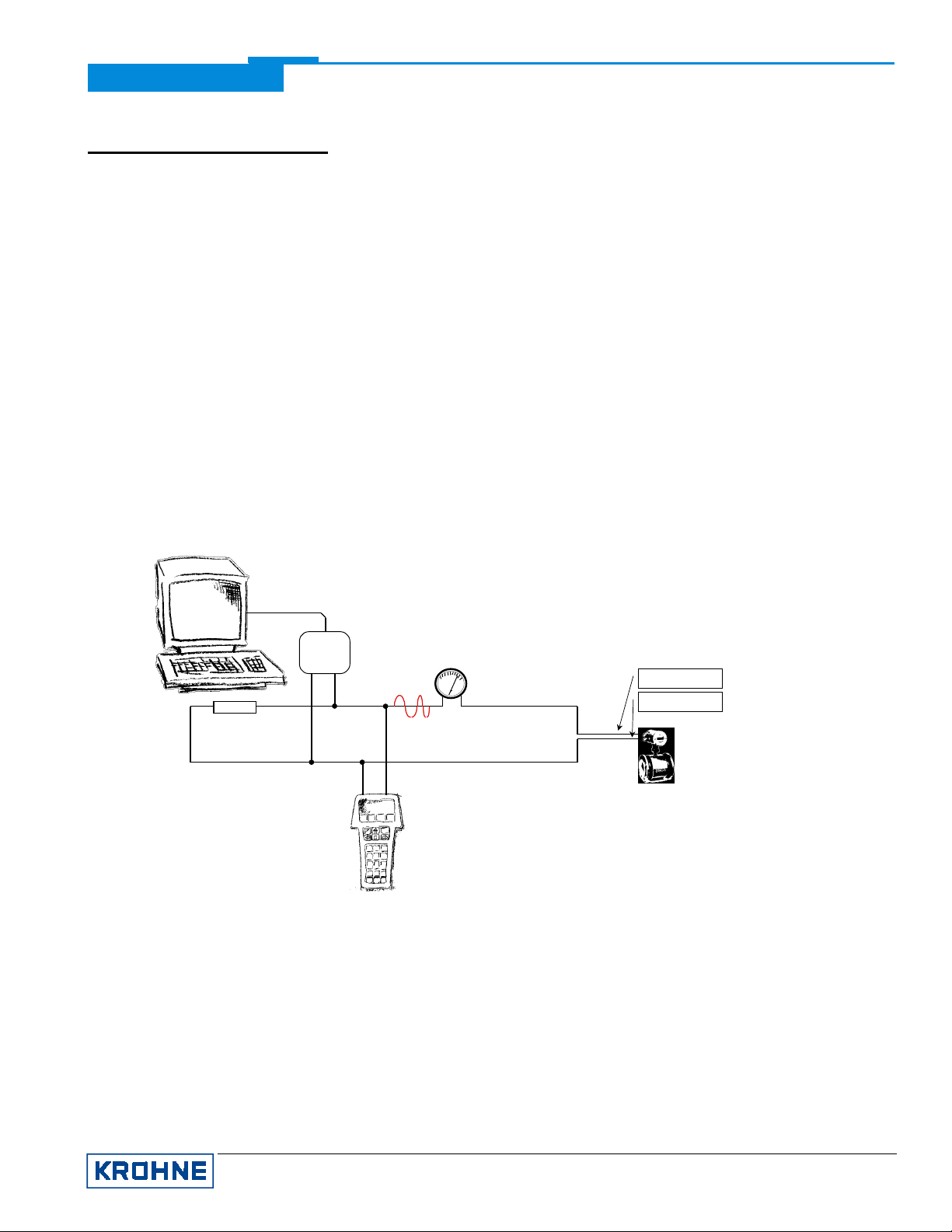
There are two ways of using the HART communication:
a) As a point-to-point connection between the IFC090 and the HART master equipment. The instrument may be
equipped with either active or pass ive curr ent out put ( ‘Modis ’) or be conf igure d with des ir ed current output (‘Standard
+ HART’).
Point-to-Point Analog/Digital Mode
Primary Master
250 Ω
≥≥≥≥
Secondary Master
HART
Modem
HART
Analog
mA
4
20
4...20 mA
Terminal I
Terminal I
IFC090
Addr. 0
(active Current Output)
+
⊥
b) As a multipoint connection (multidrop) with up to 15 devices (IFC090 or other HART equipment) in parallel. The
instruments must be equipped (or configured) with passive current output.
KROHNE Messtechnik GmbH & Co. KG · Ludwig-Krohne-Str. 5 ! D-47058 Duisburg
Tel.: 0203-301 0 ! Fax: 0203-301 389 · e-mail: krohne@krohne.de
3/8
Page 4

Power
Supply
250 Ω
≥≥≥≥
Primary Master
HART
Modem
Remote Operation Instructions IFC090 HART
Multidrop Mode
HART
Terminal I
4 mA 4 mA
Terminal I
. . .
⊥
Secondary Master Up to 15
IFC090
Addr. > 0
(passive Current Output)
Slaves
. . .
IFC090
Addr. > 0
(passive Current Output)
2 IDs and Revision numbers
The HART Device Descriptions described in this document have the following IDs and revision numbers:
Manufacturer ID: 69 (0x45)
Device Type: 244 (0xF4)
Device Revision: 2
DD Revision: 1
HART Universal Revision: 5
HC 275 OS Revision:
AMS Version:
For information about Transmitter Revisions and related Device Descriptions refer to the KROHNE HART Device
List.
≥
≥
4.9
5.0
3 Implementation Peculiarities
Variables and functions/processes of the
layer. Still a subset of service parameters is transferred via bus (only reading is possible): it applies to variables that
control the limits, availability, etc. of maintenance data.
Service Menu
are not maintained by the instrument HART® application
4 HART Communicator 275 (HC275)
4.1 Installation
The HC275 has to be programmed with the IFC090 HART Device Description. Otherwise the HC275 user will work
with the instrument as a generic one thus loosing opportunity for entire instrument control.
KROHNE Messtechnik GmbH & Co. KG · Ludwig-Krohne-Str. 5 ! D-47058 Duisburg
Tel.: 0203-301 0 ! Fax: 0203-301 389 · e-mail: krohne@krohne.de
4/8
Page 5

Remote Operation Instructions IFC090 HART
4.2 Operating
Refer to the IFC090 Menu Tree HC275 (Attachment A).
The IFC090 operation via HC275 is made quite close to the manual instrument control via keypad.
The online help of each parameter contains its function number as a reference to the device’s local display and the
“Installation and Operating Instructions”.
Parameter protection via password (Entry Code) is the same as on local display. Please refer to the online help for
valid symbols according to device’s keypad.
While saving configuration to HC275 from connected instrument, some crucial service variables (refer to section 2)
are also stored. Hence in the offline mode their values cannot be changed (and will not be sent to device), but are
shown to HC275 user and control assignments for maintenance data.
As soon as service functionality is not available via HART transmitter, the difference between “standard
configuration” of HC275 and its “full configuration” consists in some read-only parameters (sensor limits, device
modules’ IDs, etc.) that are either transferred to AMS (“full configuration”) or are shown on AMS tabs as empty fields
(“standard configuration”).
5 Asset Management Solutions (AMS)
5.1 Installation
If the IFC090 Device Description is not already installed on the AMS System a so called
AMS
is needed (available on floppy disk from KROHNE or as download from KROHNE Internet page).
For installing the DD with the Installation Kit refer to the
“Adding new Device Types to AMS”
“Install Device Types Manually”
/
“AMS User's Guide”
.
section 3:
Installation Kit IFC090 HART
”Managing HART Devices”
/
5.2 Operating
Refer to the IFC090 Menu Tree AMS (Attachment B).
Due to AMS requirements and conventions the IFC090 operation differs a little from operation with HC275 and via
local keypad.
The online help of each parameter contains its function number as a reference to the device’s local display and the
“Installation and Operating Instructions”.
Parameter protection via password (Entry Code) is the same as on local display. Please refer to the online help for
valid symbols according to device’s keypad.
KROHNE Messtechnik GmbH & Co. KG · Ludwig-Krohne-Str. 5 ! D-47058 Duisburg
Tel.: 0203-301 0 ! Fax: 0203-301 389 · e-mail: krohne@krohne.de
5/8
Page 6

Remote Operation Instructions IFC090 HART
Attachment A
1 Process
Variables
2 Outputs/
Inputs
3 Operation
4 Test
5 Installation
IFC090 Menu Tree HC275
1 Raw Flow
2 Smoothed Flow
3 Positive Totalizer
4 Negative Totalizer
5 Totalizers’ Sum
1 Full Scale
2 Damping Control
3 Time Constant
4 Cutoff Control
*
Cutoff ‘On’ value
5
*
Cutoff ‘Off’ value
6
7 Display
8 Current Output I
opt
9
Pulse B1
opt
Control/Status B1
9
opt
10
Control/Status B2
*
Auto/Extern. Range
11
*
Trip.Point 1, Low
12
*
Trip.Point 1, High
13
14* Trip.Point 2, Low
15* Trip.Point 2, High
1 Test Range (M)
2 Hardware Info M)
3 Sensor Limits
1 Language
2 Flowmeter
3 Zero trim (M)
4 User Unit
5 Application
6 Hardware
1 Current Ou tput Value
2 PV %Range
opt
Pulse Output Value
3
opt
4
Control/Stat us B1
opt
Control/Stat us B2
5
1 Display Flow
2 Display Counters
3 Display Value P
1 Function I
2 Rev.Range Control
*
Rev.Range Scale
3
4 I 0%
5 I 100%
6 I Max
7 I Error
1 Upper Sensor Limit
2 Sensor Min Span
1 Flow
opt
2
Empty Pipe
1 Flow Units
loc
2
Flow Format
1 Totalizer Units
loc
Totalizer Format
2
1 Pulse Value Units
loc
Pulse Value Fmt
2
1 Function P
2 Pulse Type
3 Pulse Control
*
Pulse Width
4
5 Pulse Value
1 Diameter
2 Full Scale
3 GK Value
4 Field Frequency
5 Line Frequency
6 Flow Direction
1 Text Volume
2 Factor Volume
3 Text Time
4 Factor Time
6 Quit/Reset
1 Hardware
1 Terminal B1
2 Terminal B2
2 Tag
7 Set/Reset
Password (M)
8 HART
Variables
3 Device Id
4 Field Device Rev
5 Software Rev
6 Hardware Rev
7 Message
8 Descriptor
1 Counters
2 Error List (M)
1 Stop/Resume (M)
2 Reset Counters (M)
9 Date
10 Final asmbly num
11 PV Sensor serial num
12 Num response preams
13 Polling address
Designations:
opt
– Optional item, depends on device implementation: availability of Binary Terminals B1/B2 and their assignment, etc.;
N* – Availability of the item depends on the assignment made for some previous item(s): say, cutoff values become
visible/editable only if ‘Cutoff Control’ parameter is set to “Yes”;
loc
– Local HC275 variable, that is not read/written to instrument;
(M) – Method is invoked to retrieve/change data.
KROHNE IFC090 45f40201
KROHNE Messtechnik GmbH & Co. KG · Ludwig-Krohne-Str. 5 ! D-47058 Duisburg
Tel.: 0203-301 0 ! Fax: 0203-301 389 · e-mail: krohne@krohne.de
6/8
Page 7

Attachment B
Process Variables
Status
Scan Device
-----------------------------------
Diagnostics and Test
Calibrate
----------------------------------Reset totalizers
Stop/resume totalizers
Set/reset password
----------------------------------Audit Trail
Drawing Notes ...
Help ...
----------------------------------Clear Offline Configuration
Compare Configurations
Configuration Properties
Remote Operation Instructions IFC090 HART
IFC090 Menu Tree AMS
•
Flow
•
Flow, Percent Range
•
Positive Totalizer
•
Negative Totalizer
•
Totalizers’ Sum
•
Current Output
•
Pulse Output
•
Control/Status B1 State
•
Control/Status B2 State
Overview
•
Primary variable out of limits
•
Non-primary variable out of limits
•
Primary variable analog output saturated
•
Primary variable analog output fixed
•
Cold start
•
Configuration changed
•
Field device malfunction
Fatal errors
•
Analog Digital Converter fatal error
•
Device Block fatal error
•
Display module fatal error
Opt
Opt
Opt
I/O module fatal error
•
Fatal error of Current Output
•
Fatal error of Pulse Output
•
Fatal error of Control Input 1
•
Fatal error of Control Input 2
•
Fatal error of Status Output 1
•
Fatal error of Status Output 2
Opt
Opt
Opt
Opt
Opt
Data Errors
Checksum error in Parameter EEPROM
•
Checksum error in General Block
•
Checksum error in Current Block
•
Checksum error in Pulse/Frequen cy Block
•
Checksum error in Control/Indication Block
•
Checksum error in Display Block
•
Checksum error in Communication Block
Warnings
•
Current output overranged
•
Pulse output overranged
•
Counter overflow
•
Power fail detected
•
Error in IMoCom configuration
•
Analog/digital converter overranged
•
Empty pipe
Opt
Designations:
Opt
– Optional variable, depends on device implementation: availability of Binary Terminals B1/B2 and
their assignment, etc.;
– refer to the next page.
KROHNE Messtechnik GmbH & Co. KG · Ludwig-Krohne-Str. 5 ! D-47058 Duisburg
Tel.: 0203-301 0 ! Fax: 0203-301 389 · e-mail: krohne@krohne.de
Opt
KROHNE IFC090 45f40201
7/8
Page 8

Attachment B
(continued from the previous page)
Remote Operation Instructions IFC090 HART
IFC090 Menu Tree AMS
Process Variables
Status
Scan Device
----------------------------------Diagnostics and Test
Calibrate
----------------------------------Reset totalizers
Stop/resume totalizers
Set/reset password
----------------------------------Audit Trail
Drawing Notes ...
Help ...
----------------------------------Clear Offline Configuration
Compare Configurations
Configuration Properties
Loop test
Test measuring range
----------------------------Hardware information
Quit/view errors
Zero trim
Apply values
------------------------------Calibration Management
Basic Setup
•
Hardware
•
Tag
--------------------------------
•
Upper Sensor Limit
•
Sensor Minimum Span
Rd
Rd
--------------------------------
•
Time Constant
•
Flow Units
--------------------------------
•
Full Scale Value
•
Flow Min
•
Damping Control
--------------------------------
•
Termina l B1
•
Termina l B2
Rd
Opt
Opt
Designations:
Opt
– Optional variable, depends on device implementation:
availability of Binary Terminals B1/B2 and their assignment,
etc.;
Rd
– Read-only variable;
Loc
– Local AMS variable, affects only AMS faceplates and
configuration tabs and is not read/written from/to instrument.
Sensor
•
PV Sensor serial num
•
Diameter
•
GK Value
•
Flow Direction
Rd
--------------------------------
•
Upper Sensor Limit
•
Sensor Minimum Span
--------------------------------
•
Application
•
Field Frequency
•
Line Frequency
--------------------------------
•
ADC firmware Id
•
I/O firmware Id
•
Display firmware Id
Process Input
•
Flow Units
•
Totalizer Units
•
Pulse Value Units
•
Time Constant
Rd
Rd
Rd
--------------------------------
•
Flow format
Rd
•
Totalizers’ format
•
Pulse Value format
Rd
Loc
Loc
Loc
Analog Output
•
Function I
•
Rev.Range Control
•
Rev.Range Scale
•
I 0%
•
I 100%
•
I Max
•
I Error
--------------------------------
•
AO Alarm type
--------------------------------
•
Function P
•
Pulse Type
•
Pulse Control
•
Pulse Width
•
Pulse Value
Rd
Opt
Opt
Opt
Opt
Opt
--------------------------------
•
Cutoff Control
•
Cufoff ‘On’ value
•
Cutoff ‘Off‘ value
KROHNE Messtechnik GmbH & Co. KG · Ludwig-Krohne-Str. 5 ! D-47058 Duisburg
Tel.: 0203-301 0 ! Fax: 0203-301 389 · e-mail: krohne@krohne.de
Binary I/O
•
Terminal B1 Function
•
Terminal B2 Function
Opt
Opt
--------------------------------
•
Trip.Point 1, Low
•
Trip.Point 1, High
•
Trip.Point 2, Low
•
Trip.Point 2, High
•
Auto/External Range
HART
•
Tag
•
Device Id
•
Final assembly num
•
Date
•
Descriptor
•
Message
--------------------------------
•
Universal revision
•
Num request preams
•
Num response preams
•
Polling address
Rd
Rd
Rd
Device
•
Model
•
Manufacturer
•
Field device revision
•
Hardware revision
•
Software revision
•
Write protect
--------------------------------
•
Empty Pipe
--------------------------------
•
Termina l B1
•
Termina l B2
--------------------------------
•
Text Volume
•
Text Time
•
Factor Volume
•
Factor Time
Rd
Rd
Rd
Rd
Rd
Opt
Opt
Opt
KROHNE IFC090 45f40201
8/8
 Loading...