

Page 1
Quick Start
Quick Start
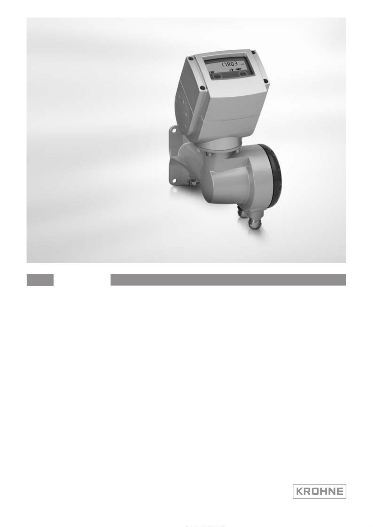
IFC 070
IFC 070
IFC 070IFC 070
Quick Start Quick Start
Electromagnetic signal converter
Electronic Revision ER 4.0.2_
The documentation is only complete when used in combination with the relevant
documentation for the sensor.
© KROHNE 11/2010 - 7311222400 - QS IFC 070 R04 en
Page 2

CONTENTS
IFC 070
1 Safety instructions 3
2 Installation 4
2.1 Notes on installation ........................................................................................................ 4
2.2 Scope of delivery............................................................................................................... 4
2.3 Transport .......................................................................................................................... 5
2.4 Pre-installation requirements ......................................................................................... 5
2.5 Installation requirements ................................................................................................ 6
2.5.1 Vibration .................................................................................................................................. 6
2.5.2 Magnetic field.......................................................................................................................... 6
2.5.3 Installation of converter.......................................................................................................... 6
3 Electrical connections 7
3.1 Safety instructions............................................................................................................ 7
3.2 Grounding ......................................................................................................................... 7
3.3 Signal cable ...................................................................................................................... 8
3.4 Connection of signal cable ............................................................................................... 8
4 Start-up 9
4.1 Connection of battery ....................................................................................................... 9
4.1.1 Internal battery .......................................................................................................................9
4.1.2 External battery .................................................................................................................... 10
5 Notes 11
2
www.krohne.com 11/2010 - 7311222400 - QS IFC 070 R04 en
Page 3
IFC 070
SAFETY INSTRUCTIONS 1
Warnings and symbols used
DANGER!
This information refers to the immediate danger when working with electricity.
DANGER!
These warnings must be observed without fail. Even partial disregard of this warning can lead to
serious health problems and even death. There is also the risk of seriously damaging the device
or parts of the operator's plant.
WARNING!
Disregarding this safety warning, even if only in part, poses the risk of serious health problems.
There is also the risk of damaging the device or parts of the operator's plant.
CAUTION!
Disregarding these instructions can result in damage to the device or to parts of the operator's
plant.
INFORMATION!
These instructions contain important information for the handling of the device.
HANDLING
• This symbol designates all instructions for actions to be carried out by the operator in the
specified sequence.
i RESULT
RESULT
RESULTRESULT
This symbol refers to all important consequences of the previous actions.
Safety instructions for the operator
CAUTION!
Installation, assembly, start-up and maintenance may only be performed by appropriately
trained personnel. The regional occupational health and safety directives must always be
observed.
LEGAL NOTICE!
The responsibility as to the suitability and intended use of this device rests solely with the user.
The supplier assumes no responsibility in the event of improper use by the customer. Improper
installation and operation may lead to loss of warranty. In addition, the "Terms and Conditions of
Sale" apply which form the basis of the purchase contract.
INFORMATION!
•
Further information can be found on the supplied CD-ROM in the manual, on the data sheet,
in special manuals, certificates and on the manufacturer's website.
•
If you need to return the device to the manufacturer or supplier, please fill out the form
contained on the CD-ROM and send it with the device. Unfortunately, the manufacturer
cannot repair or inspect the device without the completed form.
www.krohne.com11/2010 - 7311222400 - QS IFC 070 R04 en
3
Page 4
2 INSTALLATION
2.1 Notes on installation
INFORMATION!
Inspect the cartons carefully for damage or signs of rough handling. Report damage to the
carrier and to the local office of the manufacturer.
INFORMATION!
Check the packing list to check if you received completely all that you ordered.
INFORMATION!
Look at the device nameplate to ensure that the device is delivered according to your order.
Check for the correct supply voltage printed on the nameplate.
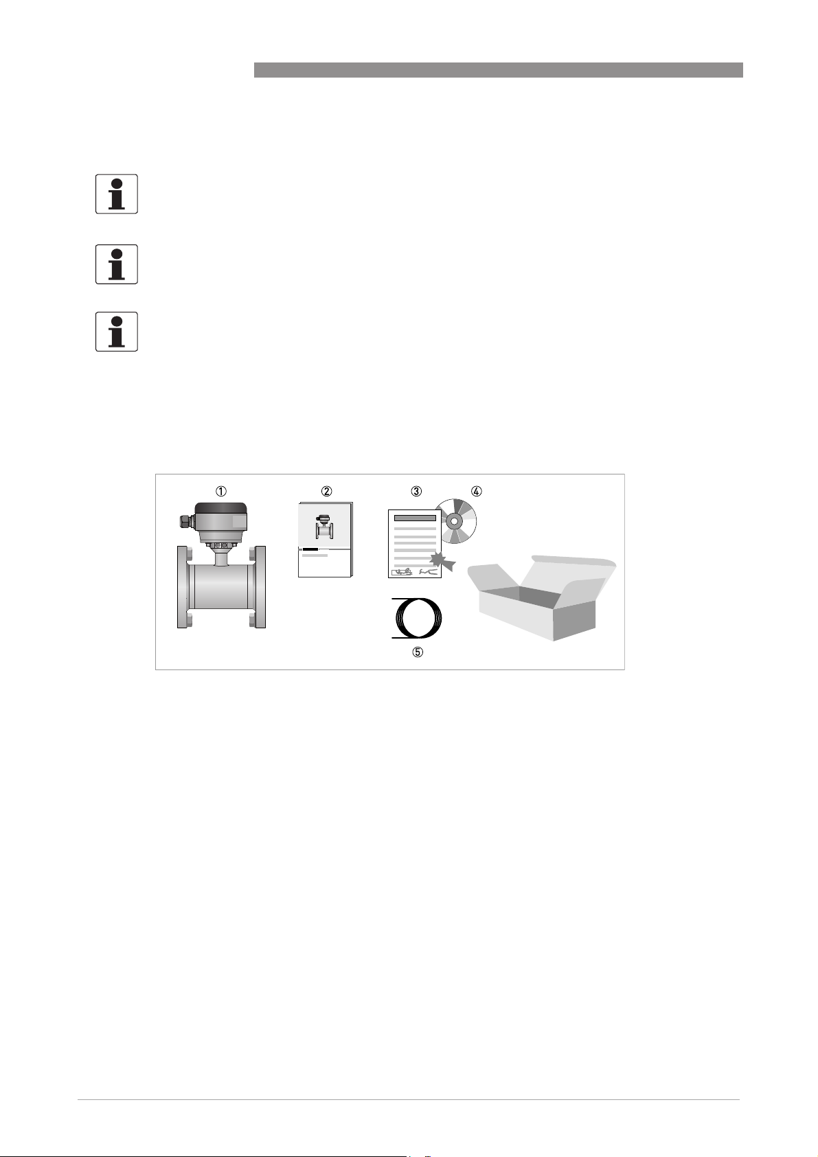
2.2 Scope of delivery
IFC 070
Figure 2-1: Scope of delivery
1 Ordered flowmeter
2 Quick Start
3 Factory calibration report
4 CD-ROM with product documentation
5 Cable (remote versions only)
4
www.krohne.com 11/2010 - 7311222400 - QS IFC 070 R04 en
Page 5

IFC 070
2.3 Transport
Figure 2-2: Transport
2.4 Pre-installation requirements
INSTALLATION 2
Make sure that you have all necessary tools available:
• Allen key (4 mm)
• Small screwdriver
• Wrench for cable glands
• Wrench for wall mounting bracket (remote version only)
• Torque wrench for installing flowmeter in pipeline
www.krohne.com11/2010 - 7311222400 - QS IFC 070 R04 en
5
Page 6

2 INSTALLATION
2.5 Installation requirements
2.5.1 Vibration
Figure 2-3: Vibration
2.5.2 Magnetic field
IFC 070
Figure 2-4: Magnetic field
2.5.3 Installation of converter
INFORMATION!
Only applicable for remote versions.
• Mount converter with mounting plate on wall or standpipe.
• Keep distance between sensor and signal converter as short as possible.
• Observe length of the delivered signal cable.
6
www.krohne.com 11/2010 - 7311222400 - QS IFC 070 R04 en
Page 7

IFC 070
3.1 Safety instructions
DANGER!
All work on the electrical connections may only be carried out with the power disconnected. Take
note of the voltage data on the nameplate!
DANGER!
Observe the national regulations for electrical installations!
WARNING!
Observe without fail the local occupational health and safety regulations. Any work done on the
electrical components of the measuring device may only be carried out by properly trained
specialists.
INFORMATION!
Look at the device nameplate to ensure that the device is delivered according to your order.
Check for the correct supply voltage printed on the nameplate.
ELECTRICAL CONNECTIONS 3
3.2 Grounding
Figure 3-1: Grounding
www.krohne.com11/2010 - 7311222400 - QS IFC 070 R04 en
7
Page 8

3 ELECTRICAL CONNECTIONS
3.3 Signal cable
CAUTION!
To ensure smooth functioning, always use the signal cables included in the delivery.
INFORMATION!
You only receive a signal cable if you ordered a remote version.
3.4 Connection of signal cable
INFORMATION!
The signal cable is only used with remote versions. The standard WSC-cable includes both
electrode and field current leads, the optional type A / B cable is only used for the electrodes. In
that case, the field current cable is no part of the supply.
IFC 070
Figure 3-2: Cable connection at converter side, standard cable
1 cable length: 13 cm / 5"
2 cable length: 5 cm / 2"
3 brown + white cable, used for field current
4 pink and grey cable, used for electrode signals
5 cable length: 8 cm / 3"
6 Shield (terminal 1 of connector X2 + U-clamp
• Prepare appropriate cable lengths (1...3)
• Connect the shield to the U-clamp, the brown cable to terminal 7 and the white to terminal 8.
• Connect the shield to terminal 1, the pink cable (white in case of type A or B cable) to terminal
2 and the grey (red in case of type A or B cable) to terminal 3.
8
www.krohne.com 11/2010 - 7311222400 - QS IFC 070 R04 en
Page 9

IFC 070
4.1 Connection of battery
CAUTION!
Please connect battery before first use, see relevant chapter for your type of battery.
Each converter is always delivered with a disconnected battery.
START-UP 4
Figure 4-1: Connecting battery
4.1.1 Internal battery
• Remove the blue protection cap.
• Loosen the 4 Allen bolts (4 mm).
• Remove the cover.
• Fasten the battery connector to the internal connector in the converter.
• Check that the display lights up.
• Put the cover back.
WARNING!
Make sure that the battery cable is not jammed by the cover.
• Tighten the 4 Allen bolts.
• Put the blue protection cap back.
INFORMATION!
The instrument now operates with factory set parameters.
For configuration of these settings, please refer to the handbook and/or the documentation of
the converter.
www.krohne.com11/2010 - 7311222400 - QS IFC 070 R04 en
9
Page 10

4 START-UP
4.1.2 External battery
• Remove the blue protection cap.
• Loosen the 4 Allen bolts (4 mm).
• Remove the cover.
• Remove one of the blind cable glands in the bottom of the converter housing.
• Remove the metal strip at the bottom of the housing (2 screws).
• Lead the cable of the external battery through the gland opening and mount the attached cable
gland loosely.
• Pull the cable to the top of the electronics.
• Fasten the battery connector to the internal connector in the converter.
• Check that the display lights up.
• Refit the metal strip at the bottom of the housing.
• Tighten the cable gland.
• Put the cover back.
WARNING!
Make sure that the battery cable is not jammed by the cover.
IFC 070
• Tighten the 4 Allen bolts.
• Put the blue protection cap back.
INFORMATION!
The instrument now operates with factory set parameters.
For configuration of these settings, please refer to the handbook and/or the documentation of
the converter.
10
www.krohne.com 11/2010 - 7311222400 - QS IFC 070 R04 en
Page 11

IFC 070
NOTES 5
www.krohne.com11/2010 - 7311222400 - QS IFC 070 R04 en
11
Page 12

KROHNE product overview
• Electromagnetic flowmeters
• Variable area flowmeters
• Ultrasonic flowmeters
• Mass flowmeters
• Vortex flowmeters
• Flow controllers
• Level meters
• Temperature meters
• Pressure meters
• Analysis products
• Measuring systems for the oil and gas industry
• Measuring systems for sea-going tankers
Head Office KROHNE Messtechnik GmbH
Ludwig-Krohne-Str. 5
D-47058 Duisburg (Germany)
Tel.:+49 (0)203 301 0
Fax:+49 (0)203 301 10389
info@krohne.de
The current list of all KROHNE contacts and addresses can be found at:
© KROHNE 11/2010 - 7311222400 - QS IFC 070 R04 en - Subject to change without notice.
www.krohne.com
 Loading...