

Page 1

Handbook
Handbook
IFC 070
IFC 070
IFC 070IFC 070
HandbookHandbook
Electromagnetic signal converter
Electronic Revision ER 4.0.0_
The documentation is only complete when used in combination with the relevant
documentation for the sensor.
© KROHNE 11/2009 - 7311242200 - MA IFC 070 R02
Page 2

: IMPRINT ::::::::::::::::::::::::::::::::::
All rights reserved. It is prohibited to reproduce this documentation, or any part thereof, without
the prior written authorisation of KROHNE Messtechnik GmbH.
Subject to change without notice.
Copyright 2009 by
KROHNE Messtechnik GmbH - Ludwig-Krohne-Str. 5 - 47058 Duisburg (Germany)
2
www.krohne.com 11/2009 - 7311242200 - MA IFC 070 R02
Page 3

IFC 070
CONTENTS
1 Safety instructions 5
1.1 Software versions............................................................................................................. 5
1.2 Intended use ..................................................................................................................... 5
1.3 Transportation, handling and using instruction for batteries ......................................... 6
1.4 Safety instructions from the manufacturer ..................................................................... 6
1.4.1 Copyright and data protection ................................................................................................ 6
1.4.2 Disclaimer ............................................................................................................................... 7
1.4.3 Product liability and warranty ................................................................................................ 8
1.4.4 Information concerning the documentation........................................................................... 8
1.4.5 Warnings and symbols used................................................................................................... 9
1.5 Safety instructions for the operator................................................................................. 9
2 Device description 10
2.1 Instrument description................................................................................................... 10
2.2 Scope of delivery............................................................................................................. 10
2.3 Nameplate ...................................................................................................................... 11
3 Installation 12
3.1 Notes on installation ......................................................................................................12
3.2 Storage ........................................................................................................................... 12
3.3 Transport ........................................................................................................................ 12
3.4 Pre-installation requirements ....................................................................................... 12
3.5 Installation requirements .............................................................................................. 13
3.5.1 Vibration ................................................................................................................................ 13
3.5.2 Magnetic field........................................................................................................................ 13
3.5.3 Installation of converter........................................................................................................ 13
4 Electrical connections 14
4.1 Safety instructions.......................................................................................................... 14
4.2 Grounding ....................................................................................................................... 14
4.3 Signal cable .................................................................................................................... 14
4.4 Connection of signal cable ............................................................................................. 15
4.5 Terminal assignment of converter................................................................................. 16
5 Start-up 17
5.1 Connection of battery ..................................................................................................... 17
5.1.1 Internal battery ..................................................................................................................... 17
5.1.2 External battery .................................................................................................................... 17
6 Operation 19
6.1 Display and operating elements .................................................................................... 19
6.2 Menu of converter ..........................................................................................................19
www.krohne.com11/2009 - 7311242200 - MA IFC 070 R02
3
Page 4

CONTENTS
IFC 070
7 Service 24
7.1 Replacement of battery .................................................................................................. 24
7.1.1 Replacement of internal battery........................................................................................... 24
7.1.2 Replacement of external battery..........................................................................................25
7.2 Spare parts availability...................................................................................................26
7.3 Availability of services .................................................................................................... 26
7.4 Returning the device to the manufacturer..................................................................... 26
7.4.1 General information.............................................................................................................. 26
7.4.2 Form (for copying) to accompany a returned device............................................................ 28
7.5 Disposal .......................................................................................................................... 28
8 Technical data 29
8.1 Measuring principle........................................................................................................29
8.2 Technical data................................................................................................................. 30
8.3 Measuring accuracy ....................................................................................................... 33
8.4 Dimensions and weights ................................................................................................ 33
9 Notes 34
4
www.krohne.com 11/2009 - 7311242200 - MA IFC 070 R02
Page 5

IFC 070
1.1 Software versions
For all GDC devices, the "Electronic Revision" (ER) is consulted to document the revision status
of the electronics according to NE 53. It is easy to see from the ER whether any fault repairs or
major changes to the electronic equipment have taken place and what effect they have had on
compatibility.
Changes and effect on compatibility
1 Downwards compatible changes and fault repair with no effect on operation (e.g. spelling
mistakes on display)
3-_ Downwards compatible hardware and/or software change of inputs and outputs:
P Pulse output
S Status output
X all inputs and outputs
4 Downwards compatible changes with new functions
5 Incompatible changes, i.e. electronic equipment must be changed.
SAFETY INSTRUCTIONS 1
Release date Electronic revision Changes and
2009 ER2.3.1_
2009 ER4.0.0_
CAUTION!
The OPTIFLUX 2070 and the WATERFLUX 3070 are different instruments with different software.
The difference lies in the Electronic Revision number, which can be found on a sticker on the
IFC 070 electronics. The electronics are therefore not compatible with each other!
1.2 Intended use
This signal converter IFC 070 has been designed to be combined with a WATERFLUX 3000 water
meter or with an OPTIFLUX 2000 flow sensor, for measuring potable water and water with
suspended particles.
This device features not only accurate flow measurement, but also continuous diagnostics in
accordance with applicable standards. This self-diagnosis monitors and automatically reports
improper functioning of the electronics, or faulty sensor electrodes. It reports battery charge
condition and even provides a cable-break alarm.
Documentation
compatibility
Initial software version MA IFC 070 R01
(SW. REV. 2.3.1_)
1; 3-P; 3-S; 4 MA IFC 070 R02
(SW. REV. 4.0.4_)
www.krohne.com11/2009 - 7311242200 - MA IFC 070 R02
5
Page 6

1 SAFETY INSTRUCTIONS
1.3 Transportation, handling and using instruction for batteries
WARNING!
The used lithium batteries are primary power sources with high energy content. If mistreated,
they may present a potential risk.
INFORMATION!
The manufacturer assumes no liability for customer failure.
Please observe the following transportation, handling and using instructions:
• Transport only in special packaging with special labels and transportation documents.
• Do not short-circuit, recharge, overcharge or connect with false polarity.
• Do not expose to temperature beyond the specified temperature range or incinerate the
battery.
• Do not crush, puncture or open cells or disassemble battery packs.
• Do not weld or solder to the body of the battery.
• Do not expose contents of battery to water.
• Remove the battery from device before returning to the manufacturer for service or warranty
reasons.
• Dispose battery packs in accordance with local regulations; where possible, recycle used
batteries.
IFC 070
1.4 Safety instructions from the manufacturer
1.4.1 Copyright and data protection
The contents of this document have been created with great care. Nevertheless, we provide no
guarantee that the contents are correct, complete or up-to-date.
The contents and works in this document are subject to German copyright. Contributions from
third parties are identified as such. Reproduction, processing, dissemination and any type of use
beyond what is permitted under copyright requires written authorisation from the respective
author and/or the manufacturer.
The manufacturer tries always to observe the copyrights of others, and to draw on works created
in-house or works in the public domain.
The collection of personal data (such as names, street addresses or e-mail addresses) in the
manufacturer's documents is always on a voluntary basis whenever possible. Whenever
feasible, it is always possible to make use of the offerings and services without providing any
personal data.
We draw your attention to the fact that data transmission over the Internet (e.g. when
communicating by e-mail) may involve gaps in security. It is not possible to protect such data
completely against access by third parties.
We hereby expressly prohibit the use of the contact data published as part of our duty to publish
an imprint for the purpose of sending us any advertising or informational materials that we have
not expressly requested.
6
www.krohne.com 11/2009 - 7311242200 - MA IFC 070 R02
Page 7

IFC 070
1.4.2 Disclaimer
The manufacturer will not be liable for any damage of any kind by using its product, including,
but not limited to direct, indirect, incidental, punitive and consequential damages.
This disclaimer does not apply in case the manufacturer has acted on purpose or with gross
negligence. In the event any applicable law does not allow such limitations on implied warranties
or the exclusion of limitation of certain damages, you may, if such law applies to you, not be
subject to some or all of the above disclaimer, exclusions or limitations.
Any product purchased from the manufacturer is warranted in accordance with the relevant
product documentation and our Terms and Conditions of Sale.
The manufacturer reserves the right to alter the content of its documents, including this
disclaimer in any way, at any time, for any reason, without prior notification, and will not be liable
in any way for possible consequences of such changes.
SAFETY INSTRUCTIONS 1
www.krohne.com11/2009 - 7311242200 - MA IFC 070 R02
7
Page 8

1 SAFETY INSTRUCTIONS
1.4.3 Product liability and warranty
The operator shall bear responsibility for the suitability of the device for the specific purpose.
The manufacturer accepts no liability for the consequences of misuse by the operator. Improper
installation and operation of the devices (systems) will cause the warranty to be void. The
respective "Standard Terms and Conditions" which form the basis for the sales contract shall
also apply.
1.4.4 Information concerning the documentation
To prevent any injury to the user or damage to the device it is essential that you read the
information in this document and observe applicable national standards, safety requirements
and accident prevention regulations.
If this document is not in your native language and if you have any problems understanding the
text, we advise you to contact your local office for assistance. The manufacturer can not accept
responsibility for any damage or injury caused by misunderstanding of the information in this
document.
This document is provided to help you establish operating conditions, which will permit safe and
efficient use of this device. Special considerations and precautions are also described in the
document, which appear in the form of underneath icons.
IFC 070
8
www.krohne.com 11/2009 - 7311242200 - MA IFC 070 R02
Page 9
IFC 070
1.4.5 Warnings and symbols used
Safety warnings are indicated by the following symbols.
DANGER!
This information refers to the immediate danger when working with electricity.
DANGER!
This warning refers to the immediate danger of burns caused by heat or hot surfaces.
DANGER!
These warnings must be observed without fail. Even partial disregard of this warning can lead to
serious health problems and even death. There is also the risk of seriously damaging the device
or parts of the operator's plant.
WARNING!
Disregarding this safety warning, even if only in part, poses the risk of serious health problems.
There is also the risk of damaging the device or parts of the operator's plant.
SAFETY INSTRUCTIONS 1
CAUTION!
Disregarding these instructions can result in damage to the device or to parts of the operator's
plant.
INFORMATION!
These instructions contain important information for the handling of the device.
LEGAL NOTICE!
This note contains information on statutory directives and standards.
• HANDLING
HANDLING
HANDLINGHANDLING
This symbol designates all instructions for actions to be carried out by the operator in the
specified sequence.
i RESULT
RESULT
RESULTRESULT
This symbol refers to all important consequences of the previous actions.
1.5 Safety instructions for the operator
WARNING!
In general, devices from the manufacturer may only be installed, commissioned, operated and
maintained by properly trained and authorized personnel.
This document is provided to help you establish operating conditions, which will permit safe and
efficient use of this device.
www.krohne.com11/2009 - 7311242200 - MA IFC 070 R02
9
Page 10
2 DEVICE DESCRIPTION
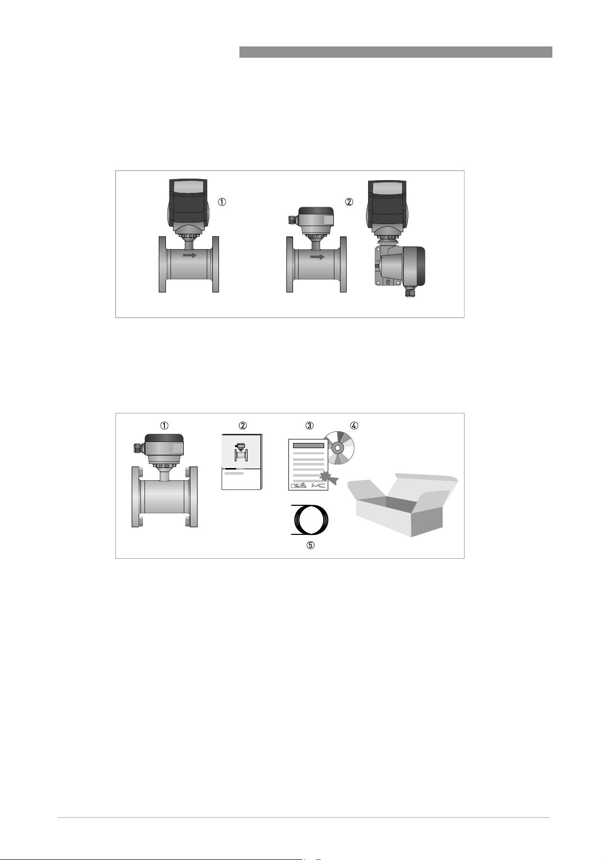
2.1 Instrument description
Two versions are available. You received a compact version or a remote version.
Figure 2-1: Versions
1 compact version
2 remote version
IFC 070
2.2 Scope of delivery
Figure 2-2: Scope of delivery
1 Ordered flowmeter
2 Quick Start
3 Factory calibration report
4 CD-ROM with product documentation
5 Cable (remote versions only)
10
www.krohne.com 11/2009 - 7311242200 - MA IFC 070 R02
Page 11
IFC 070
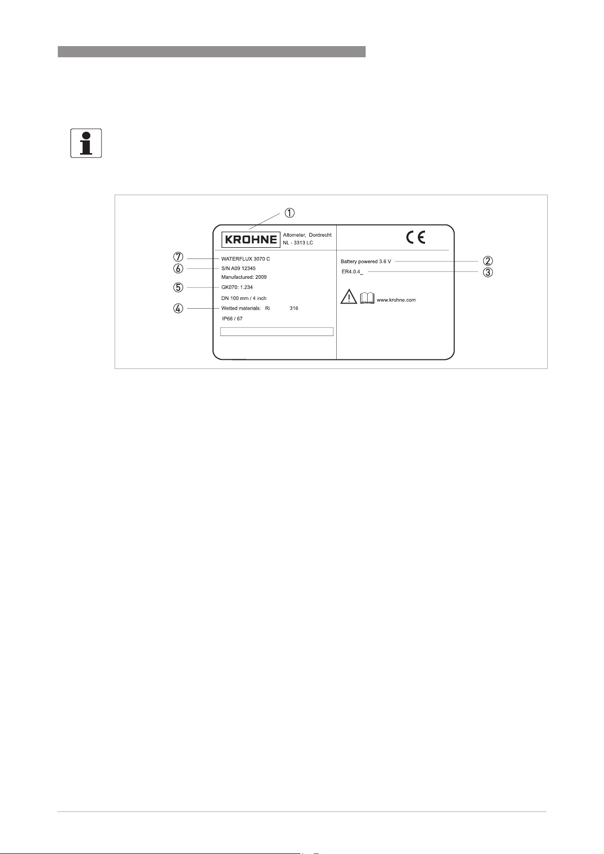
2.3 Nameplate
INFORMATION!
Look at the device nameplate to ensure that the device is delivered according to your order.
Check for the correct supply voltage printed on the nameplate.
DEVICE DESCRIPTION 2
Figure 2-3: Example for nameplate
1 Manufacturer
2 Voltage information
3 Electronic Revision number
4 Material of wetted parts
5 Meter constant
6 Serial number
7 Device type
www.krohne.com11/2009 - 7311242200 - MA IFC 070 R02
11
Page 12

3 INSTALLATION
3.1 Notes on installation
INFORMATION!
Inspect the cartons carefully for damage or signs of rough handling. Report damage to the
carrier and to the local office of the manufacturer.
INFORMATION!
Check the packing list to check if you received completely all that you ordered.
INFORMATION!
Look at the device nameplate to ensure that the device is delivered according to your order.
Check for the correct supply voltage printed on the nameplate.
3.2 Storage
• Store the device in a dry, dust-free location.
• Avoid continuous direct sunlight.
• Store the device in its original packaging.
• Storage temperature: -50 ...+70°C / -58...+158°F
IFC 070
3.3 Transport
Figure 3-1: Transport
3.4 Pre-installation requirements
Make sure that you have all necessary tools available:
• Allen key (4 mm)
• Small screwdriver
• Wrench for cable glands
• Wrench for wall mounting bracket (remote version only)
• Torque wrench for installing flowmeter in pipeline
12
www.krohne.com 11/2009 - 7311242200 - MA IFC 070 R02
Page 13

IFC 070
3.5 Installation requirements
3.5.1 Vibration
Figure 3-2: Vibration
3.5.2 Magnetic field
INSTALLATION 3
Figure 3-3: Magnetic field
3.5.3 Installation of converter
INFORMATION!
Only applicable for remote versions.
• Mount converter with mounting plate on wall or standpipe.
• Keep distance between sensor and signal converter as short as possible.
• Observe length of the delivered signal cable.
www.krohne.com11/2009 - 7311242200 - MA IFC 070 R02
13
Page 14

4 ELECTRICAL CONNECTIONS
4.1 Safety instructions
WARNING!
Observe without fail the local occupational health and safety regulations. Any work done on the
electrical components of the measuring device may only be carried out by properly trained
specialists.
INFORMATION!
Look at the device nameplate to ensure that the device is delivered according to your order.
Check for the correct supply voltage printed on the nameplate.
4.2 Grounding
IFC 070
Figure 4-1: Grounding
4.3 Signal cable
CAUTION!
To ensure smooth functioning, always use the signal cables included in the delivery.
INFORMATION!
You only receive a signal cable if you ordered a remote version.
14
www.krohne.com 11/2009 - 7311242200 - MA IFC 070 R02
Page 15

IFC 070
4.4 Connection of signal cable
INFORMATION!
The signal cable is only used with remote versions. The standard KROHNE WSC-cable includes
both electrode and field current leads, the optional type A / B cable is only used for the
electrodes. In that case, the field current cable is no part of the supply.
ELECTRICAL CONNECTIONS 4
Figure 4-2: Cable connection at converter side, standard cable
1 cable length: 13 cm / 5"
2 cable length: 5 cm / 2"
3 brown + white cable, used for field current
4 purple and blue cable, used for electrode signals
5 cable length: 8 cm / 3"
6 Shield (terminal 1 of connector X2 + U-clamp
• Prepare appropriate cable lengths (1...3)
• Connect the shield to the U-clamp, the brown cable to terminal 7 and the white to terminal 8.
• Connect the shield to terminal 1, the purple cable (white in case of type A or B cable) to
terminal 2 and the blue (red in case of type A or B cable) to terminal 3.
www.krohne.com11/2009 - 7311242200 - MA IFC 070 R02
15
Page 16

4 ELECTRICAL CONNECTIONS
4.5 Terminal assignment of converter
IFC 070
Figure 4-3: Removing side cap
Figure 4-4: Terminal assignment
1 Status output 1
2 Status output 2
3 Not connected
4 Ground
5 Pulse output A
6 Pulse output B
16
Electrical values
• Pulse output passive:
Pulse output passive:
Pulse output passive:Pulse output passive:
f ≤ 500 Hz; I ≤ 10 mA; U: 2.7...24 VDC (P ≤ 100 mW)
• Status output passive:
Status output passive:
Status output passive:Status output passive:
I ≤ 10 mA; U: 2.7...24 VDC (P ≤ 100 mW)
www.krohne.com 11/2009 - 7311242200 - MA IFC 070 R02
Page 17

IFC 070
5.1 Connection of battery
CAUTION!
Please connect battery before first use, see relevant chapter for your type of battery.
Each converter is always delivered with a disconnected battery.
START-UP 5
Figure 5-1: Connecting battery
5.1.1 Internal battery
• Remove the blue protection cap.
• Loosen the 4 Allen bolts (4 mm).
• Remove the cover.
• Fasten the battery connector to the internal connector in the converter.
• Check that the display lights up.
• Put the cover back.
WARNING!
Make sure that the battery cable is not jammed by the cover.
• Tighten the 4 Allen bolts.
• Put the blue protection cap back.
INFORMATION!
The instrument now operates with factory set parameters.
For configuration of these settings, please refer to the handbook and/or the documentation of
the converter.
5.1.2 External battery
• Remove the blue protection cap.
• Loosen the 4 Allen bolts (4 mm).
• Remove the cover.
• Remove one of the blind cable glands in the bottom of the converter housing.
• Remove the metal strip at the bottom of the housing (2 screws).
• Lead the cable of the external battery through the gland opening and mount the attached cable
gland loosely.
• Pull the cable to the top of the electronics.
• Fasten the battery connector to the internal connector in the IFC 070 converter.
www.krohne.com11/2009 - 7311242200 - MA IFC 070 R02
17
Page 18

5 START-UP
• Check that the display lights up.
• Refit the metal strip at the bottom of the housing.
• Tighten the cable gland.
• Put the cover back.
WARNING!
Make sure that the battery cable is not jammed by the cover.
• Tighten the 4 Allen bolts.
• Put the blue protection cap back.
INFORMATION!
The instrument now operates with factory set parameters.
For configuration of these settings, please refer to the handbook and/or the documentation of
the converter.
IFC 070
18
www.krohne.com 11/2009 - 7311242200 - MA IFC 070 R02
Page 19

IFC 070
6.1 Display and operating elements
1 battery status
2 optical key V to navigate through the menu and to scroll through the measuring pages
3 reset button (only accessible with removed cover)
4 flow direction
5 measured value and measuring unit
6 optical key Z to navigate through the menu
OPERATION 6
6.2 Menu of converter
• To enter the menu, hold the V and Z key for 5 seconds.
i The display flashes.
• Press the Z key to enter the menu.
i You see the menu number at the left (12 at the beginning) and the value at the right side of
the display.
• Scroll through the available positions with the V key to the position you want to change.
• Press the Z key to enter the value.
i The value flashes.
• Use the Z and V key to change the value.
• Hold the Z key for 3 seconds to confirm the new value.
• To leave the programming mode, hold the V key for 3 seconds to store the new value(s). If you
do not want to store the new values, do not touch any key for 60 seconds.
Other functions:
• software version: press Z key for 1 second
• display test: press Z key twice for 1 second
www.krohne.com11/2009 - 7311242200 - MA IFC 070 R02
19
Page 20

6 OPERATION
CAUTION!
Take care with changing menu number 13. If you set this to "1", the display locks. IF this
happens:
• Remove the protection cap.
• Loosen the 4 Allen bolts (4 mm).
• Remove the cover.
• Press both keys simultaneously and press the reset button for 6 seconds as shown in the
graph below. Use a small screwdriver for the reset button.
• Display starts with the menu, beginning with menu no. 12.
• Go to menu no. 13 and change 1 into 0.
• Hold the Z key for 3 seconds to confirm the new value.
• Put the cover back.
IFC 070
Figure 6-1: Entering the menu if menu no. 13 is set to 1 (fiscal metering active)
WARNING!
Make sure that the battery cable is not jammed by the cover.
• Tighten the 4 Allen bolts.
• Put the blue protection cap back.
20
www.krohne.com 11/2009 - 7311242200 - MA IFC 070 R02
Page 21

IFC 070
Software version 4.0.4_
OPERATION 6
Menu
No.
12 Measuring unit 0
13 Access control 0 0 = Standard Fiscal metering blocks menu, refer to
20 Meter type 0 0 = WATERFLUX 3070 Select "0" in case of a square cross
21 Meter size 100 Defined at factory calibration Choose from table, in chosen unit
22 Meter constant 01.000 Defined at factory calibration Meter constant is shown on typeplate.
23 Zero offset
24 Zero selection 0 0 = factory calibration Selection which zero point to use
25 Flow direction 0 0 = Forward -
26 Measuring rate 15 1, 5, 10, 15, 20 seconds Measurement interval in seconds
27 Low flow cut off 10 0, 5, 10 mm/s Measurements below this value are
28 Time constant
30 Self check 0 0 = off Is automatically switched on at fiscal
31 Empty pipe
32 Simulate outputs 0 0 = off If set to on, display shows 0 and 1
41 Output A (pulse) 0 0 = off Set pulse rate in menu no. 45
42 Output B (pulse) 0 0 = off Set pulse rate in menu no. 45
43 Phase shift
44 Pulse width 1 1, 5, 10, 50, 100 ms Choose from table
45 Pulse value 00.100 in m3/pulse or 100 USG/pulse -
Description Display
default
0 Set to 1 In situ determination of zero point.
calibration
2 1 = fast, Time constant of display
flow reading
0 0 = off If switched on, display shows "- EP -".
detection
90 90 degrees offset
between pulse
outputs
Selection list Remarks
0 = m3/h
1 = USG/min
2 = l/s
1 = Fiscal metering
1 = OPTIFLUX 2070
Confirm with “>” for 3 seconds After countdown meter switches to
1 = measured
1 = Reverse
2 = normal
3 = slow
1 = on
1 = on
1 = on (1 pulse per second)
1 = on
1 = on
180 degrees offset
F-r ( A - forward flow, B - reverse
flow)
Customer defined
figure above this table.
section, select "1" in case of a round
cross section.
(menu no. 12).
measuring mode.
Menu no. 24 is automatically set to 1.
neglected
metering (menu no. 13 = 1)
See graph below this table.
alternately (independent of setting in
menu no. 41/42). Set to "0" to stop the
simulation.
www.krohne.com11/2009 - 7311242200 - MA IFC 070 R02
21
Page 22

6 OPERATION
Software version 4.0.4_
IFC 070
Menu
No.
51 Status output 1
52 Status output 1
53 Status output 1
54 Status output 1
55 Status output 2
56 Status output 2
57 Status output 2
58 Status output 2
59 Status outputs
60 Show flow rate 0 0 = off -
61 Show counter
63 Show counter
65 Show net counter 1 0 = off -
66 All counters
71 Counters
72 All errors reset 0 Set to 1 After reset display value is back to 0
73 Battery type 2 0 = non (external power supply) Wrong setting influences battery
74 Battery capacity 19.000 Value in Ah -
Description Display
default
0 0 = off Active at instrument failure, e.g. coil,
Self checking
0 0 = off Active at low battery (10% left). Can be
Battery pre
warning
0 0 = off Active at very low battery (1% left).
Battery final
warning
0 0 = off Active if counter goes from 99999999
Counter overrun
0 0 = off Active at instrument failure. Can be
Self checking
0 0 = off Active at low battery (10% left). Can be
Battery pre
warning
0 0 = off Active at very low battery (1% left).
Battery final
warning
0 0 = off Active if counter goes from 99999999
Counter overrun
1 0 = off Pulse width determined by menu no.
pulsating
0 0 = off forward
0 0 = off reverse
88888 Set to 00000 After reset display value is back to
reset
1 0 = stop For service / maintenance purposes,
run/stop
Selection list Remarks
1 = on
1 = on
1 = on
1 = on
1 = on
1 = on
1 = on
1 = on
1 = on
1 = on
1 = on
1 = on
1 = on
Confirm with “>” for 3 seconds
1 = run
Confirm with “>” for 3 seconds
1 = single (19 Ah)
2 = dual (38 Ah)
3 = external (76 Ah)
electrode, battery. Can be reset by
menu no. 72.
reset by menu no. 72.
Can be reset by menu no. 72.
to 00000000. Can be reset by menu no.
72.
reset by menu no. 72.
reset by menu no. 72.
Can be reset by menu no. 72.
to 00000000. Can be reset by menu no.
72.
44. Can be reset by menu no. 72.
88888
pulse output also stops.
lifetime calculation.
22
www.krohne.com 11/2009 - 7311242200 - MA IFC 070 R02
Page 23

IFC 070
Software version 4.0.4_
OPERATION 6
Menu
Description Display
No.
75 Reset battery life
76 Load default
77 Fiscal metering
time counter
settings
verification
reading
Empty pipe detection
Selection list Remarks
default
0 Set to 1 After reset menu value is back to 0.
Confirm with “>” for 3 seconds
0 Set to 1 After reset menu value is back to 0,
Confirm with “>” for 3 seconds
0 0 = off Test modus, for verification at/by
1 = on
manual reprogramming necessary.
authority, display indicates P8888888,
decimal separator position varies per
diameter.
Figure 6-2: Display in Empty Pipe situation (if menu 31 is set to "1")
www.krohne.com11/2009 - 7311242200 - MA IFC 070 R02
23
Page 24

7 SERVICE
7.1 Replacement of battery
Different type of batteries with different capacities are available. They can be exchanged by other
types if wanted.
IFC 070
Figure 7-1: Batteries with cable and connector
1 Internal battery in holder
2 Internal dual pack battery
3 Internal single pack battery
4 External battery pack
7.1.1 Replacement of internal battery
24
Figure 7-2: Removing battery
• Remove the protection cap.
• Loosen the 4 Allen bolts (4 mm).
• Remove the cover.
• Disconnect the connector of the battery.
www.krohne.com 11/2009 - 7311242200 - MA IFC 070 R02
Page 25

IFC 070
SERVICE 7
• Remove the battery holder by pulling it upwards.
• Remove the battery from the holder.
• Insert the new battery in the holder.
• Replace the holder.
• Fasten the battery connector to the internal connector in the converter.
• Check that the display lights up.
• Replace the cover.
WARNING!
Make sure that the battery cable is not jammed by the cover.
• Tighten the 4 bolts.
• Enter the programming mode, hold the V and Z key for 5 seconds.
i The display flashes.
• Press the Z key to enter the menu.
• Scroll through the available positions with the V key to position 74 and check the battery
capacity (important for battery life indication):
- internal single pack battery: 19 Ah
- internal dual pack battery: 38 Ah
- External battery pack: 76 Ah
• Go to position 75 and enter "1" (reset battery counter).
i Battery capacity symbol at the display should be "full".
• Hold the V key for 3 seconds to confirm the new value and go back to the measuring mode.
• Put the blue protection cap back.
7.1.2 Replacement of external battery
Figure 7-3: Removing metal strip
• Remove the blue protection cap.
• Loosen the 4 Allen bolts (4 mm).
• Remove the cover.
• Loosen the used cable gland in the bottom of the converter housing.
• Remove the metal strip at the bottom of the housing (2 screws).
• Disconnect the connector of the battery.
• Remove the cable of the old battery.
www.krohne.com11/2009 - 7311242200 - MA IFC 070 R02
25
Page 26

7 SERVICE
• Lead the cable of the new external battery through the gland opening and mount the attached
cable gland loosely.
• Pull the cable to the top of the electronics.
• Fasten the battery connector to the internal connector in the IFC 070 converter.
• Check that the display lights up.
• Refit the metal strip at the bottom of the housing.
• Tighten the cable gland.
• Put the cover back.
WARNING!
Make sure that the battery cable is not jammed by the cover.
• Tighten the 4 bolts.
• Enter the programming mode, hold the V and Z key for 5 seconds.
i The display flashes.
• Press the Z key to enter the menu.
• Scroll through the available positions with the V key to position 74 and check the battery
capacity (important for battery life indication):
- internal single pack battery: 19 Ah
- internal dual pack battery: 38 Ah
- External battery pack: 76 Ah
• Go to position 75 and enter "1" (reset battery counter).
i Battery capacity symbol at the display should be "full".
IFC 070
• Hold the V key for 3 seconds to confirm the new value and go back to the measuring mode.
• Put the blue protection cap back.
7.2 Spare parts availability
The manufacturer adheres to the basic principle that functionally adequate spare parts for each
device or each important accessory part will be kept available for a period of 3 years after
delivery of the last production run for the device.
This regulation only applies to spare parts which are under normal operating conditions subjects
to wear and tear.
7.3 Availability of services
The manufacturer offers a range of services to support the customer after expiration of the
warranty. These include repair, technical support and training.
INFORMATION!
For more precise information, please contact your local representative.
7.4 Returning the device to the manufacturer
7.4.1 General information
This device has been carefully manufactured and tested. If installed and operated in accordance
with these operating instructions, it will rarely present any problems.
26
www.krohne.com 11/2009 - 7311242200 - MA IFC 070 R02
Page 27

IFC 070
SERVICE 7
CAUTION!
Should you nevertheless need to return a device for inspection or repair, please pay strict
attention to the following points:
•
Due to statutory regulations on environmental protection and safeguarding the health and
safety of our personnel, manufacturer may only handle, test and repair returned devices that
have been in contact with products without risk to personnel and environment.
•
This means that the manufacturer can only service this device if it is accompanied by the
following certificate (see next section) confirming that the device is safe to handle.
CAUTION!
If the device has been operated with toxic, caustic, flammable or water-endangering products,
you are kindly requested:
•
to check and ensure, if necessary by rinsing or neutralizing, that all cavities are free from
such dangerous substances,
•
to enclose a certificate with the device confirming that is safe to handle and stating the
product used.
www.krohne.com11/2009 - 7311242200 - MA IFC 070 R02
27
Page 28

7 SERVICE
7.4.2 Form (for copying) to accompany a returned device
Company: Address:
Department: Name:
Tel. no.: Fax no.:
Manufacturer's order no. or serial no.:
The device has been operated with the following medium:
IFC 070
This medium is: water-hazardous
toxic
caustic
flammable
We checked that all cavities in the device are free from such
substances.
We have flushed out and neutralized all cavities in the
device.
We hereby confirm that there is no risk to persons or the environment through any residual media
contained in the device when it is returned.
Date: Signature:
Stamp:
7.5 Disposal
CAUTION!
Disposal must be carried out in accordance with legislation applicable in your country.
28
www.krohne.com 11/2009 - 7311242200 - MA IFC 070 R02
Page 29

IFC 070
8.1 Measuring principle
An electrically conductive fluid flows inside an electrically insulating pipe through a magnetic
field. This magnetic field is generated by a current, flowing through a pair of field coils. Inside of
the fluid, a voltage U is generated:
U = v * k * B * D
U = v * k * B * D
U = v * k * B * DU = v * k * B * D
in which:
v = mean flow velocity
k = factor correcting for geometry
B = magnetic field strength
D = inner diameter of flow meter
The signal voltage U is picked off by electrodes and is proportional to the mean flow velocity v
and thus the flow rate q. The signal voltage is quite small (typically 1 mV at v = 3 m/s / 10 ft/s and
field coil power of 1 W). Finally, a signal converter is used to amplify the signal voltage, filter it
(separate from noise) and convert it into signals for totalising, recording and output processing.
TECHNICAL DATA 8
1 Induced voltage (proportional to flow velocity)
2 Electrodes
3 Magnetic field
4 Field coils
www.krohne.com11/2009 - 7311242200 - MA IFC 070 R02
29
Page 30

8 TECHNICAL DATA
8.2 Technical data
INFORMATION!
•
The following data is provided for general applications. If you require data that is more
relevant to your specific application, please contact us or your local representative.
•
Additional information (certificates, special tools, software,...) and complete product
documentation can be downloaded free of charge from the website (Download Center).
Measuring system
Measuring principle Faraday's law
Application range Electrically conductive fluids
Measured value
Measured value
Measured valueMeasured value
Primary measured value Flow velocity
Secondary measured value Volume flow
Design
Modular construction The measurement system consists of a flow sensor and a signal
Compact version With WATERFLUX 3000 sensor: WATERFLUX 3070 C
Remote version With WATERFLUX 3000 sensor: WATERFLUX 3070 F
User interface
User interface
User interfaceUser interface
Display 8 digits LCD
Units
IFC 070
converter. It is available as compact and as remote version. More
information about the sensor can be found in the relevant
documentation.
With OPTIFLUX 2000 sensor: OPTIFLUX 2070 C
With OPTIFLUX 2000 sensor: OPTIFLUX 2070 F
Maximum cable length 25 m / 75 ft
Display of positive and negative counter, sum counter, flow rate
Status indication for battery, flow / counter direction, empty pipe
Volume in m3, US Gallons
30
Flow rate in m3/h, USGPM, l/s
Cable connections Standard: 2x M20x1.5
Optional: ½" NPT, PF½
Measuring accuracy
Reference conditions Medium: water
Temperature: 20°C / 68°F
Inlet section: 5 DN
Operating pressure: 1 bar / 14.5 psig
Maximum measuring error ±0.2% of measured value ±0.5 mm/s / 0.02 inch/s
For detailed information on the measuring accuracy, see chapter
"Measuring accuracy".
Repeatability ±0.1% (v > 0.5 m/s / 1.5 ft/s)
www.krohne.com 11/2009 - 7311242200 - MA IFC 070 R02
Page 31

IFC 070
TECHNICAL DATA 8
Operating conditions
Temperature
Temperature
TemperatureTemperature
Process temperature -5…+70°C / 23…+158°F
Ambient temperature -40…+65°C / -40…+149°F
Storage temperature -50…+70°C / -58…+158°F
Chemical properties
Chemical properties
Chemical propertiesChemical properties
Physical condition Liquids
Electrical conductivity ≥ 20 μS/cm
Recommended flow velocity -9...9 m/s / -30...30 ft/s
Process conditions Raw water, ground- and surface water
Potable water
Irrigation water
Installation conditions
Dimensions and weights For detailed information see chapter "Dimensions and weights".
Materials
Housing Die-cast aluminium, polyurethane coated
Connection box (remote versions
only)
Die-cast aluminium, polyurethane coated
Electrical connections
Power supply
Power supply
Power supplyPower supply
Battery Standard
Typical lifetime See graph at the end of this table.
Alarm Pre-alarm at 10% of energy left
Battery replacement Possible without loss of totalizer data
In- and output
In- and output
In- and outputIn- and output
Outputs 2 Passive pulse outputs for remote totalising:
Communication Optional: external data logger / GSM module, SMS protocol to:
Standard
StandardStandard
1 Lithium battery (D-cell)
Optional
Optional
OptionalOptional
2 Lithium batteries (D-cell)
External battery pack with 4 lithium batteries (D-cell, IP 68)
Final alarm at 1% of energy left
f ≤ 500 Hz; I ≤ 10 mA; U: 2.7...24 VDC (P ≤ 100 mW)
2 Passive status outputs:
I ≤ 10 mA; U: 2.7...24 VDC (P ≤ 100 mW)
SCADA system (at customer's site)
OPC server (to be connected to customer's OPC client)
PCWin (mini-SCADA can be supplied by us)
www.krohne.com11/2009 - 7311242200 - MA IFC 070 R02
31
Page 32

8 TECHNICAL DATA
Approvals and certificates
CE
CE
CECE
Electromagnetic compatibility Directive: 2004/108/EC
Low voltage directive Directive: 2006/95/EC
Hazardous areas
Hazardous areas
Hazardous areasHazardous areas
Non-Ex Standard
ATEX Not available
Other approvals and standards
Other approvals and standards
Other approvals and standardsOther approvals and standards
Custody transfer Standard: without verification
Protection category acc. to
IEC 529 / EN 60529
Shock- and vibration resistance IEC 68-2-3
IFC 070
This device fulfills the statutory requirements of the EC directives.
The manufacturer certifies successful testing of the product by
applying the CE mark.
Harmonized standard: EN 61326-1 : 2006
Harmonized standard: EN 61010 : 2001
MI-001 type examination certificate for DN50...200, pending for other
diameters.
OIML R-49 certificate of conformity for DN50...200, pending for other
diameters.
Conform EN 14154 / ISO 4064
IP 66/67 (NEMA 4/4X/6)
Typical lifetime of batteries (at 25°C) for a DN80
Figure 8-1: XXXX = Sampling interval in seconds, YYYY = typical lifetime in years
1 dual battery pack
2 single battery
32
www.krohne.com 11/2009 - 7311242200 - MA IFC 070 R02
Page 33

IFC 070
8.3 Measuring accuracy
TECHNICAL DATA 8
Figure 8-2: XXXX = flow velocity [m/s], YYYY = deviation from the actual measured value [%]
1 with WATERFLUX 3000 water meter
2 with OPTIFLUX 2000 flow sensor
8.4 Dimensions and weights
Compact version
Compact version
Compact versionCompact version
Remote version, signal converter
Remote version, signal converter
Remote version, signal converterRemote version, signal converter
a = 170 mm / 6.7"
b = 132 mm / 5.3"
c = 140 mm / 5.5"
Weight of converter = 1.9 kg / 4.2 lbs
Sizes of sensor can be found in the relevant
datasheet.
b = 122 mm / 4.8"
c = 235 mm / 9.3"
H = 310 mm / 12.2"
Weight of converter = 3.3 kg / 7.3 lbs
www.krohne.com11/2009 - 7311242200 - MA IFC 070 R02
33
Page 34

9 NOTES
IFC 070
34
www.krohne.com 11/2009 - 7311242200 - MA IFC 070 R02
Page 35

IFC 070
NOTES 9
www.krohne.com11/2009 - 7311242200 - MA IFC 070 R02
35
Page 36

KROHNE product overview
• Electromagnetic flowmeters
• Variable area flowmeters
• Ultrasonic flowmeters
• Mass flowmeters
• Vortex flowmeters
• Flow controllers
• Level meters
• Temperature meters
• Pressure meters
• Analysis products
• Measuring systems for the oil and gas industry
• Measuring systems for sea-going tankers
Head Office KROHNE Messtechnik GmbH
Ludwig-Krohne-Str. 5
D-47058 Duisburg (Germany)
Tel.:+49 (0)203 301 0
Fax:+49 (0)203 301 10389
info@krohne.de
© KROHNE 11/2009 - 7311242200 - MA IFC 070 R02 - Subject to change without notice.
The current list of all KROHNE contacts and addresses can be found at:
www.krohne.com
 Loading...