

KROHNE IFC 050 Specifications
Technical Datasheet
Technical Datasheet
IFC 050
IFC 050
IFC 050IFC 050
Technical DatasheetTechnical Datasheet
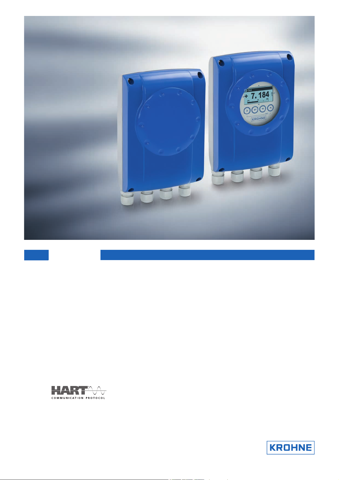
Signal converter for electromagnetic flowmeters
•
For simple applications
•
Multiple outputs, incl. active pulse output and RS485 Modbus
•
Excellent price/performance ratio
The documentation is only complete when used in combination with the relevant
documentation for the flow sensor.
© KROHNE 09/2016 - 4002183703 - TD IFC 050 R03 en

CONTENTS
IFC 050
1 Product features 3
1.1 The standard for simple applications .............................................................................. 3
1.2 Options and variants......................................................................................................... 5
1.3 Signal converter/flow sensor combination possibilities ................................................. 6
1.4 Measuring principle.......................................................................................................... 6
2 Technical data 7
2.1 Technical data................................................................................................................... 7
2.2 Dimensions and weight .................................................................................................. 14
2.2.1 Housing ................................................................................................................................. 14
2.2.2 Mounting plate, wall version................................................................................................. 16
2.3 Flow tables ..................................................................................................................... 17
2.4 Measuring accuracy ....................................................................................................... 19
3 Installation 20
3.1 Intended use ................................................................................................................... 20
3.2 Installation specifications .............................................................................................. 20
3.3 Mounting of the compact version................................................................................... 20
3.4 Mounting of the wall housing, remote version .............................................................. 20
4 Electrical connections 22
4.1 Safety instructions.......................................................................................................... 22
4.2 Preparing the signal and field current cables ............................................................... 22
4.2.1 Signal cable A (type DS 300), construction........................................................................... 22
4.2.2 Length of signal cable A........................................................................................................ 23
4.2.3 Connection diagram for signal and field current cable ....................................................... 24
4.3 Grounding the flow sensor ............................................................................................. 25
4.4 Connecting the power supply......................................................................................... 25
4.5 Inputs and outputs, overview ......................................................................................... 27
4.5.1 Description of the CG number .............................................................................................. 27
4.5.2 Fixed, non-alterable output versions ................................................................................... 27
4.6 Laying electrical cables correctly .................................................................................. 28
5 Notes 29
2
www.krohne.com 09/2016 - 4002183703 - TD IFC 050 R03 en

IFC 050
1.1 The standard for simple applications
PRODUCT FEATURES
1
The electromagnetic signal converter IFC 050
in various kinds of applications in the water industry but also in the food and beverage business.
The signal converter can be combined with the flow sensors OPTIFLUX 1000, 2000, 4000, 6000
and the WATERFLUX 3000. The output represents measured values for flow, mass and
conductivity.
IFC 050 is a perfect choice for measuring volumetric flow
IFC 050IFC 050
This low-cost signal converter has some specific features:
• An active pulse output for a simple system, like driving an electro-mechanical counter
• RS485 Modbus communication with a data processing system
• Extra insulation of the electronic device and housing for high performance in areas with
extreme humidity and chances for flooding
• Cost-effective flow measurement for a wide range of process conditions and still a very
acceptable degree of accuracy
1 Large graphic display with 4 magnet keys for operating the signal converter when the housing is closed
2 4 push buttons to operate the signal converter when the housing is open
3 Supply voltage: 100…230 VAC and 24 VDC
www.krohne.com09/2016 - 4002183703 - TD IFC 050 R03 en
3

1
PRODUCT FEATURES
Highlights
• Available outputs: current output (incl. HART®), active pulse/frequency output, status output
and Modbus
• Intuitive operation with touch buttons
• Excellent price/performance ratio
• Modern robust housing design
• Asymmetric mounting possible
• All versions with and without display are available
• Simple installation and start-up
• Bright graphic display
• A variety of operating languages integrated as standard
• Certified tests for humidity and vibration
• Extremely quick signal conversion
Industries
• Water & Wastewater
• Food & Beverage
• Heating, Ventilation & Air Conditioning (HVAC)
• Agriculture
• Steel
IFC 050
Applications
• Water and wastewater treatment
• Water distribution network
• Irrigation installation
• Water abstraction
• CIP cleaning stations
4
www.krohne.com 09/2016 - 4002183703 - TD IFC 050 R03 en

IFC 050
1.2 Options and variants
Modular signal converter concept with display
PRODUCT FEATURES
The modular concept gives the opportunity to
combine the IFC 050 with the flow sensors
OPTIFLUX 1000, OPTIFLUX 2000, OPTIFLUX 4000,
OPTIFLUX 6000 and the WATERFLUX 3000.
With respect to the housing versions, both a compact
and a remote design are available. The signal
converter for the compact version is directly
mounted under a 10° angle to the flow sensor for
easy reading of the display after rainfall or frost.
If the measuring point is difficult to access or if the
ambient conditions like temperature effects and
vibration prevent the use of the compact version, a
remote signal converter with a wall housing is
available.
1
Remote version in wall housing with display
Remote version in wall housing without display
A signal cable is used to connect the flow sensor to
the signal converter for power supply and signal
processing.
The same electronic unit can be used in both
(Compact + Wall) versions without configuration.
A blind version is the perfect option in a situation
where the display is not required and the menu will
be approached once a time.
A separate display can be easily connected to the
electronic unit to enter the menu. This tool will be
provided as a spare part.
www.krohne.com09/2016 - 4002183703 - TD IFC 050 R03 en
5
1
PRODUCT FEATURES
1.3 Signal converter/flow sensor combination possibilities
Flow sensor Flow sensor + signal converter IFC 050
Compact Remote wall-mounted
housing
OPTIFLUX 1000 OPTIFLUX 1050 C OPTIFLUX 1050 W
OPTIFLUX 2000 OPTIFLUX 2050 C OPTIFLUX 2050 W
OPTIFLUX 4000 OPTIFLUX 4050 C OPTIFLUX 4050 W
OPTIFLUX 6000 OPTIFLUX 6050 C OPTIFLUX 6050 W
WATERFLUX 3000 WATERFLUX 3050 C WATERFLUX 3050 W
1.4 Measuring principle
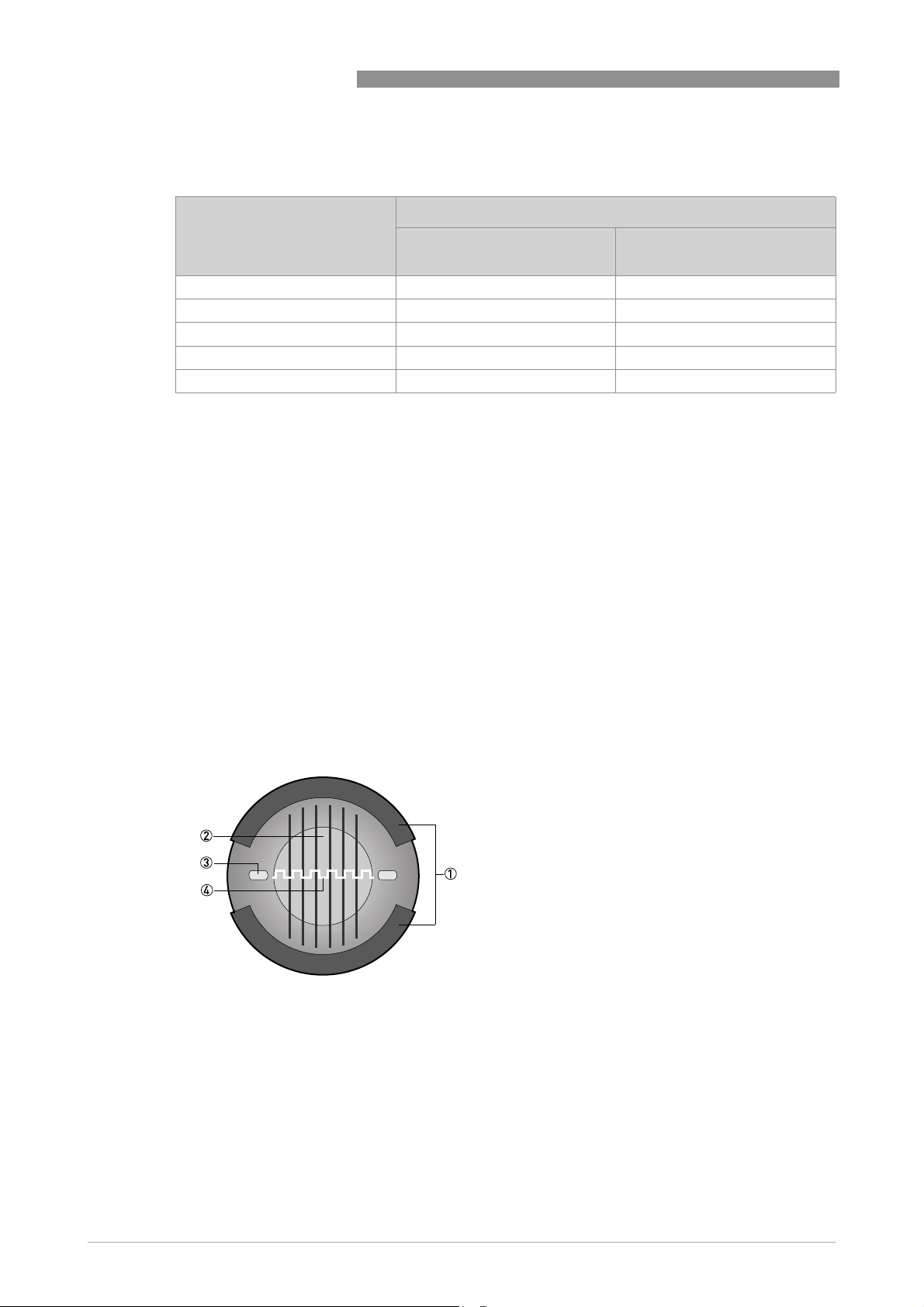
An electrically conductive fluid flows inside an electrically insulated pipe through a magnetic
field. This magnetic field is generated by a current, flowing through a pair of field coils.
Inside of the fluid, a voltage U is generated:
U = v * k * B * D
U = v * k * B * D
U = v * k * B * DU = v * k * B * D
IFC 050
in which:
v = mean flow velocity
k = factor correcting for geometry
B = magnetic field strength
D = inner diameter of flowmeter
The signal voltage U is picked off by electrodes and is proportional to the mean flow velocity v
and thus the flow rate Q. A signal converter is used to amplify the signal voltage, filter it and
convert it into signals for totalizing, recording and output processing.
Figure 1-1: Measuring principle
1 Field coils
2 Magnetic field
3 Electrodes
4 Induced voltage (proportional to flow velocity)
6
www.krohne.com 09/2016 - 4002183703 - TD IFC 050 R03 en

IFC 050
TECHNICAL DATA
2.1 Technical data
•
The following data is provided for general applications. If you require data that is more
relevant to your specific application, please contact us or your local sales office.
•
Additional information (certificates, special tools, software,...) and complete product
documentation can be downloaded free of charge from the website (Downloadcenter).
Measuring system
Measuring principle Faraday's law of induction
Application range Continuous measurement of current volume flow, flow velocity, conductivity, mass
Design
Modular construction The measuring system consists of a flow sensor and a signal converter.
Flow sensor
Flow sensor
Flow sensorFlow sensor
OPTIFLUX 1000 DN10...150 / 3/8…6"
OPTIFLUX 2000 DN25...1200 / 1…48"
OPTIFLUX 4000 DN10...1200 / 3/8…48"
OPTIFLUX 6000 DN10...150 / 3/8...6"
WATERFLUX 3000 DN25...600 / 1…24"
Signal converter
Signal converter
Signal converterSignal converter
Compact version (C) IFC 050 C
Remote version (W) IFC 050 W
Options
Options
OptionsOptions
Outputs
Counter 2 internal counters with a max. of 10 counter places (e.g. for counting volume
Verification Integrated verification, diagnostic functions: measuring device, empty pipe
Communication interfaces
flow (at constant density), coil temperature of the flow sensor
Current output (incl. HART®), pulse output, frequency output, status output and/or
limit switch
Note: It's not possible to use the pulse/frequency output with the status output at
the same time!
and/or mass units)
detection, stabilisation
®
HART
Modbus
2
www.krohne.com09/2016 - 4002183703 - TD IFC 050 R03 en
7

2
TECHNICAL DATA
Display and user interface
Display and user interface
Display and user interfaceDisplay and user interface
Graphic display LC display, backlit white
Size: 128 x 64 pixels, corresponds to 59 x 31 mm = 2.32" x 1.22"
Ambient temperatures below -25°C/ -13°F may affect the readability of the display.
Operating elements 4 push buttons for operating the signal converter when the housing is open.
4 magnet keys for operating the signal converter when the housing is closed.
Remote control Only generic and not device-specific DDs and DTMs available!
PACTwareTM (including Device Type Manager (DTM))
HART® Hand Held Communicator from Emerson Process
AMS® from Emerson Process
PDM® from Siemens
All DTMs and drivers are available free of charge from the manufacturer's website.
Display functions
Display functions
Display functionsDisplay functions
Operating menu Setting the parameters using 2 measuring pages, 1 status page, 1 graphic page
Language display texts (as
language package)
Units Metric, British and US units selectable as required from lists for volume / mass flow
(measured values and graphics are freely adjustable)
Standard: English, French, German, Dutch, Portuguese, Swedish, Spanish, Italian
Eastern Europe: English, Slovenian, Czech, Hungarian
Northern Europe: English, Danish, Polish, Finnish
Southern Europe: English, Turkish
China: English, German, Chinese
Russia: English, German, Russian
and counting, flow velocity, electrical conductivity, temperature
IFC 050
Measuring accuracy
Max. measuring accuracy Standard:
Repeatability ±0.1%
Standard:
Standard:Standard:
±0.5% of the measured value ± 1mm/s
Option (optimised accuracy with extended calibration):
Option (optimised accuracy with extended calibration):
Option (optimised accuracy with extended calibration):Option (optimised accuracy with extended calibration):
±0.25% of the measured value ± 1.5 mm/s
For detailed information and accuracy curves refer to
19.
Special calibrations are available on request.
Current output electronics: ±10 µA; ±100 ppm/°C (typically: ±30 ppm/°C)
Measuring accuracy
on page
8
www.krohne.com 09/2016 - 4002183703 - TD IFC 050 R03 en

IFC 050
TECHNICAL DATA
Operating conditions
Temperature
Temperature
TemperatureTemperature
Process temperature Refer to technical data for the flow sensor.
Ambient temperature Depending on the version and combination of outputs.
It is a good idea to protect the converter from external heat sources such as direct
sunlight as higher temperatures reduce the life cycle of all electronic components.
Ambient temperatures below -25°C/ -13°F may affect the readability of the display.
Storage temperature -40…+70°C/ -40…+158°F
Pressure
Pressure
PressurePressure
Medium Refer to technical data for the flow sensor.
Ambient pressure Atmosphere
Chemical properties
Chemical properties
Chemical propertiesChemical properties
Electrical conductivity All media except for water: ≥ 5 µS/cm
State of aggregation Conductive, liquid media
Solid content (volume) ≤ 10%
Gas content (volume) ≤ 3%
Flow rate For detailed information, refer to chapter "Flow tables".
Other conditions
Other conditions
Other conditionsOther conditions
Ingress protection acc. to
IEC 529 / EN 60529
(also refer to the technical data for the flow sensor)
Water: ≥ 20 µS/cm
IP66/67 (acc. to NEMA 4/4X)
2
Installation conditions
Installation For detailed information, refer to chapter "Installation conditions".
Inlet / outlet sections Refer to technical data for the flow sensor.
Dimensions and weight For detailed information refer to chapter "Dimensions and weight".
Materials
Signal converter housing Aluminum with a polyester topcoat
Flow sensor For housing materials, process connections, liners, grounding electrodes and
gaskets, refer to technical data for the flow sensor.
www.krohne.com09/2016 - 4002183703 - TD IFC 050 R03 en
9

2
TECHNICAL DATA
Electrical connection
General Electrical connection is carried out in conformity with the VDE 0100 directive
Power supply 100…230 VAC (-15% / +10%), 50/60 Hz;
Power consumption AC: 15 VA
Signal cable Only necessary for remote versions.
Cable entries Standard: M20 x 1.5 (8...12 mm)
"Regulations for electrical power installations with line voltages up to 1000 V" or
equivalent national specifications.
240 VAC + 5% is included in the tolerance range.
24 VDC (-30% / +30%)
DC: 5.6 W
DS 300 (type A)
DS 300 (type A)
DS 300 (type A)DS 300 (type A)
Max. length: 600 m / 1968 ft (depending on electrical conductivity and flow sensor
version)
Option: ½ NPT, PF ½
Outputs
General All outputs are electrically isolated from each other and from all other circuits.
All operating data and output values can be adjusted.
Description of abbreviations U
= external voltage; RL = load + resistance;
ext
Uo = terminal voltage; I
= nominal current
nom
IFC 050
10
www.krohne.com 09/2016 - 4002183703 - TD IFC 050 R03 en
 Loading...