

KitchenAid KPEU722M, GZ7930XHS, GZ7936XHS, KIRD801HSS, KIRD802HSS Installation Instructions And Use And Care Manual
...
Quick Reference
Table of Contents:
Pages
Before you start
Electrical requirements
Product dimensions
Cabinet dimensions
Countertop cutout dimensions
Vent system requirements
Interior-mounted vent motor
Installation steps
Vent system requirements
Exterior-mounted vent motor
Installation steps
Use and Care Information
Accessories
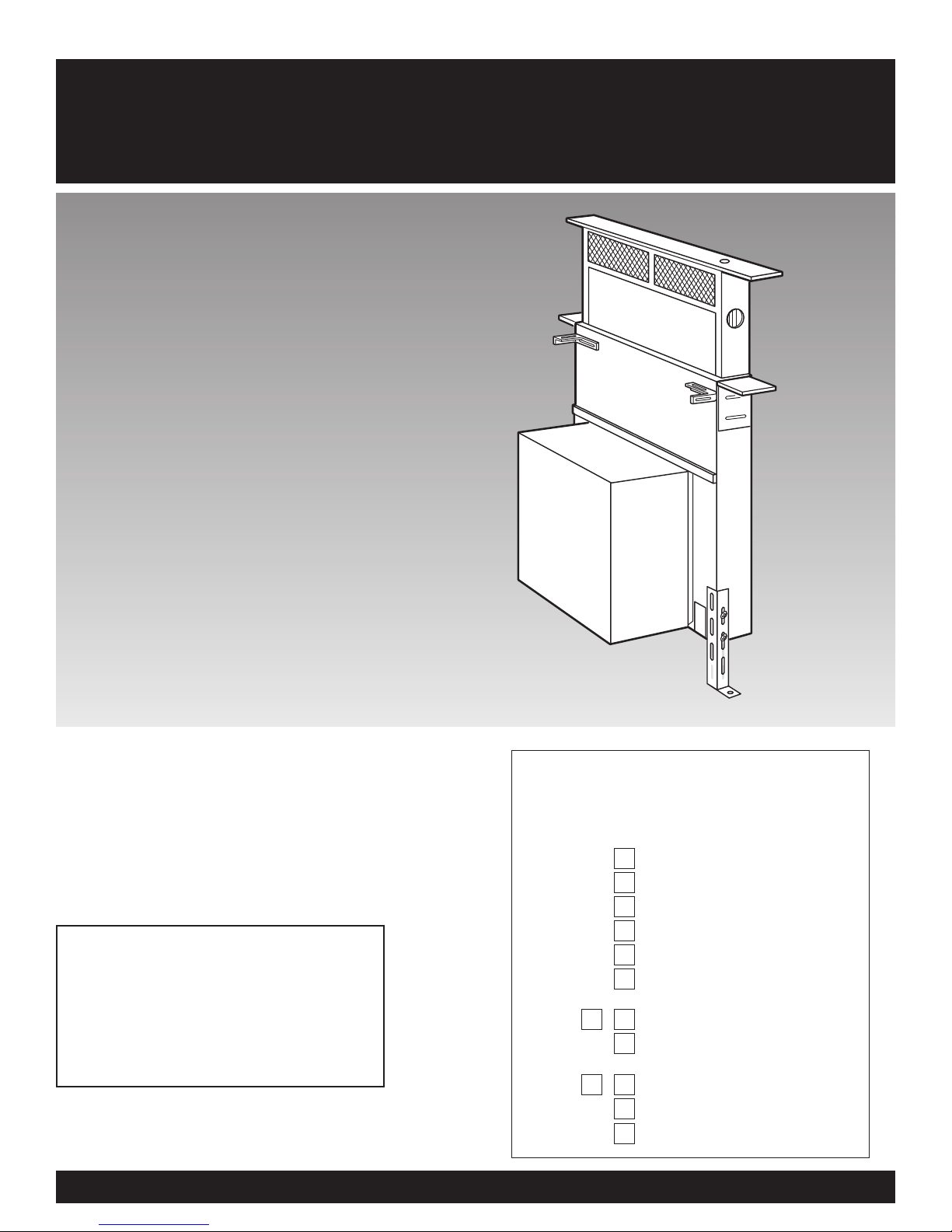
Installation Instructions and
Use and Care Guide
30" (76.2 cm)
36" (91.4 cm)
Retractable (Pop-up)
Downdraft Vent Systems
IMPORTANT:
Read and save
these instructions.
IMPORTANT:
Installer: Leave Installation Instructions with
the homeowner.
Homeowner: Keep Installation Instructions for
future reference.
Save Installation Instructions for local electrical
inspector's use.
Part No. 4329225/9763381
2
3
4
4
5
6
7- 9
9
11
12
13
10 -
Before you start...
Proper installation is your
responsibility. Make sure you have
everything necessary for correct
installation. It is the responsibility
of the installer to comply with the
installation clearances specified on
the model/serial rating plate. The
model/serial rating plate is located
on the front of the downdraft vent
above the wiring box cover.
Check location where downdraft
vent will be installed. The location
should be away from strong draft
areas, such as windows, doors and
strong heating vents or fans.
Before making countertop cutout,
check that downdraft vent and
cooktop location will clear cabinet
walls, backsplash, and rear wall
studs inside cabinet.
IMPORTANT: Observe all governing
codes and ordinances.
Failure to meet codes and
ordinances could lead to fire or
electrical shock.
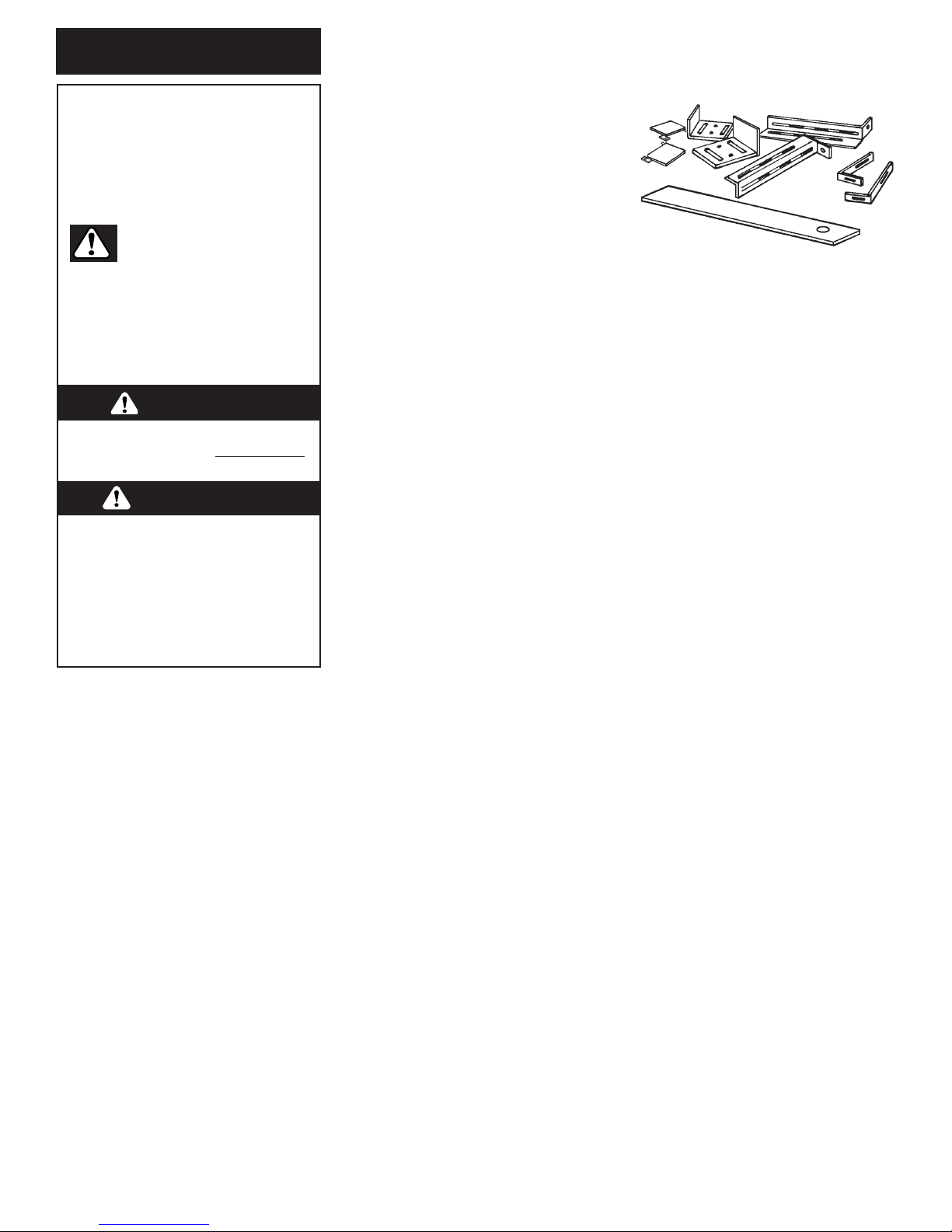
Parts supplied
for installation:
Parts needed
for installation:
Tools needed for
installation:
2
Mobile home installation
The installation of this downdraft
vent system must conform to the
Manufactured Home Construction
Safety Standards, Title 24 CFR,
Part 328 (formerly the Federal
Standard for Mobile Home
Construction and Safety, Title 24,
HUD, Part 280) or when such
standard is not applicable, the
Standard for Manufactured Home
Installation 1982 (Manufactured
Home Sites, Communities and
Setups) ANSI A225.1/NFPA 501A*,
or latest edition, or with local
codes.
All openings in the wall or floor
where retractable downdraft vent
is to be installed must be sealed.
Electrical ground is required. See
“Electrical requirements,” page 3.
When installing downdraft vent,
the cabinet drawer will need to be
removed and the drawer front
installed permanently to cabinet.
NOTE: Downdraft vent is installed
directly behind the cooktop. Install
downdraft vent first.
Cabinet construction: Downdraft
vent is designed for use in a
cabinet with a depth of 24"
(61 cm). Some installations
require a countertop deeper than
25" (63.5 cm). See chart on page 5.
The maximum depth of the
overhead cabinet is 13" (33 cm).
Overhead cabinets installed at
either side of the downdraft vent
must be 18" (45.7 cm) above the
cooking surface.
See cooktop Installation
Instructions before making any
cutouts and for the minimum
distance between the front edge
of the countertop and front edge
of cooktop. The minimum
horizontal distance between the
overhead cabinets is the same as
the width of the installed
downdraft vent.
When installing a 36" (91.4 cm)
retractable downdraft vent with
“Create-A-Cooktop” modules, the
optional support must be installed
on the front of the downdraft vent.
See installation steps for details.
• safety glasses
• gloves
• jig or keyhole saw
• drill with 1/8" drill bit
• pencil
• measuring tape
• flat-blade screwdriver
• Phillips screwdriver
• 3/8" (9.5 mm) nut driver or ratchet
• level
• pliers
• metal snips
• wire stripper or utility knife
• caulking gun and weatherproof caulk
• duct tape
• 1 top trim
• 2 end caps
• 2 lower support legs
• 2 overcounter support brackets
• 2 undercounter mounting brackets
• 1 bag of fasteners
• 1 metal cover
• 1 backdraft damper
• literature package
• optional support and two screws
(36" (91.4 cm) models only
• 2 U.L.- or C.S.A.-listed 1/2" (12.7 mm)
conduit connectors (3 are required if
the exterior-mounted vent motor
is used.)
• 1 wall cap for interior-mounted
motor
• vent system
• power supply cable
• wiring cable for optional remote
blower kit.
You can be killed or seriously
injured if you don’t follow
instructions.
DANGER
Your safety and the safety of
others are very important.
We have provided many important
safety messages in this manual
and on your appliance. Always
read and obey all safety
messages.
All safety messages will tell you
what the potential hazard is, tell you
how to reduce the chance of injury,
and tell you what can happen if the
instructions are not followed.
You can be killed or seriously
injured if you don’t immediatel
y
follow instructions.
WARNING
This is the safety alert
symbol.
This symbol alerts you to
potential hazards that can kill or
hurt you and others.
All safety messages will follow the
safety alert symbol and either the
word “DANGER” or “WARNING”.
These words mean:
3
Electrical requirements
IMPORTANT: Observe all
governing codes and ordinances.
It is the customer’s responsibility:
• To contact a qualified electrical
installer.
• To assure that the electrical
installation is adequate and in
conformance with National
Electrical Code, ANSI/NFPA 70
— latest edition*, or CSA
Standards C22.1-94, Canadian
Electrical Code, Part 1 and
C22.2 No. 0-M91 - latest
edition** and all local codes
and ordinances.
If codes permit and a separate
ground wire is used, it is
recommended that a qualified
electrician determine that the
ground path is adequate.
Do not ground to a gas pipe.
Check with a qualified electrician if
you are not sure downdraft vent is
properly grounded.
Do not have a fuse in the neutral
or ground circuit.
IMPORTANT: Save Installation
instructions for electrical
inspector’s use.
E. A U.L.- or C.S.A.-listed, 1/2"
(12.7 mm) conduit connector
must be provided at each end of
the power supply cable (at the
downdraft vent and at the
junction box).
A. A 120-volt, 60-Hz, AC-only,
fused electrical supply is required
on a separate 15 amp circuit. A
time-delay fuse or circuit breaker
is recommended. The fuse must
be sized per local codes in
accordance with the electrical
rating of the downdraft vent as
specified on the model/serial
rating plate located on the front
of the downdraft vent above the
wiring box cover.
B. The downdraft vent must
be connected with copper wire
only.
C. Wire sizes and connections
must conform to the
requirements of the National
Electrical Code, ANSI/NFPA 70 —
latest edition*, or CSA Standards
C22.1-94, Canadian Electrical
Code, Part 1 and C22.2 No. 0-M91
- latest edition** and all local
codes and ordinances.
D. This downdraft vent should
be connected directly to the fused
disconnect (or circuit breaker)
through flexible, armored or nonmetallic sheathed, copper cable.
Allow some slack in the cable so
the downdraft vent can be moved
if servicing is ever necessary.
F. A wiring diagram is located
on the downdraft vent base
above the wiring box cover.
Copies of the standards listed may be
obtained from:
* National Fire Protection Association
One Batterymarch Park
Quincy, Massachusetts 02269
**CSA International
8501 East Pleasant Valley Road
Cleveland, Ohio 44131-5575
WARNING — TO REDUCE THE
RISK OF FIRE, ELECTRIC
SHOCK, OR INJURY TO
PERSONS, OBSERVE THE
FOLLOWING:
Installation work and electrical
wiring must be done by qualified
person(s) in accordance with all
applicable Codes and Standards,
including fire related construction.
Sufficient air is needed for proper
combustion and exhausting of
gases through the flue (chimney)
of fuel burning equipment to
prevent back drafting. Follow the
heating equipment
manufacturer’s guideline and
safety standards such as those
published by the National Fire
Protection Association
(NFPA),and the American Society
of Heating Refrigeration and Air
Conditioning Engineers
(ASHRAE), and the local code
authorities.
When cutting or drilling into wall
or ceiling, do not damage
electrical wiring and other hidden
utilities.
Ducted fans must always be
vented to the outdoors.
WARNING — To reduce the risk
of fire, use only metal ductwork.
This unit must be grounded.
4
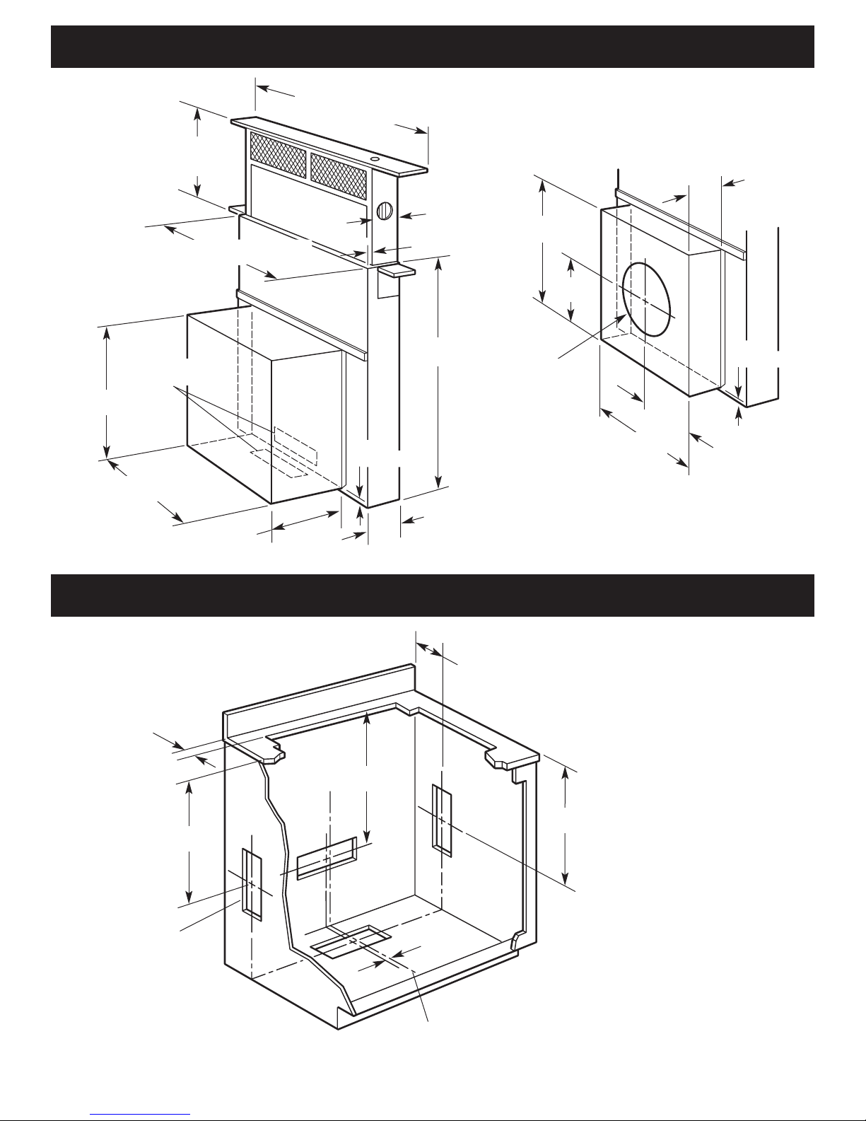
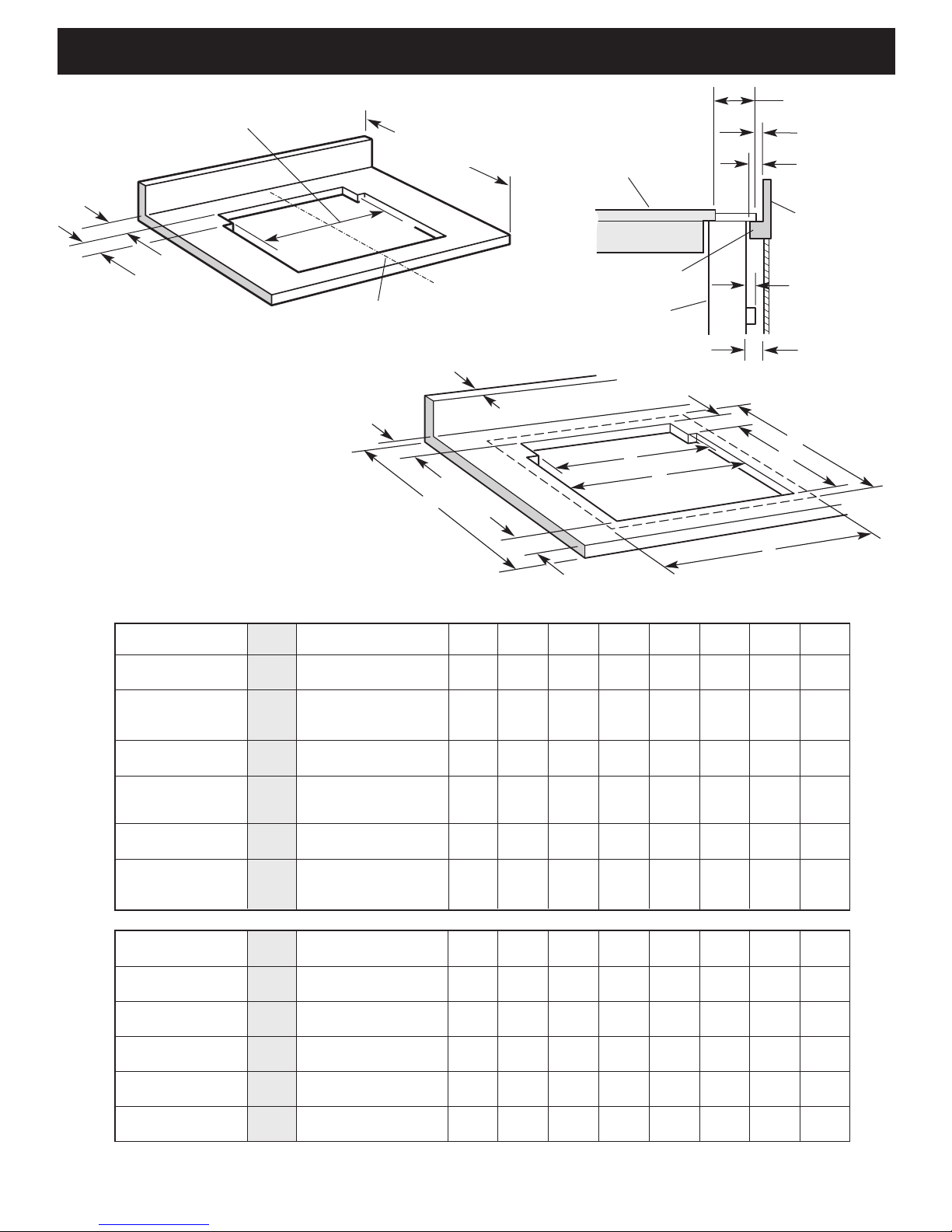
Cabinet dimensions
Product dimensions
top trim widths
30" vent (76.2 cm)
36" vent (91.4 cm)
3/8" (9.5 mm)
8-1/4" (21 cm)
retractable
vent height
1-1/2"
(3.8 cm)
26-1/8"
(66.4 cm)
2-1/8”
(54 cm)
INTERNAL
BLOWER
MOTOR
EXTERIOR-MOUNTED
BLOWER MOTOR
5/8"
(15.9 mm)
4"
(10.2 cm)
8"
(20.3 cm)
9" (22.9 cm) Dia.
NOTE: A 10" (2.5
cm) round vent
system adapter
collar attaches over
this hole. Adapter
collar is supplied
with exterior
blower.
16"
(40.6 cm)
8"
(20,3 cm)
16"
(40.6 cm)
5/8"
(15.9 mm)
9-3/8"
(23.8 cm)
16"
(40.6 cm)
16"
(40.6 cm)
4-1/8"+A
(10.5 cm)
17-9/16"
(44.6 cm)
17-3/16"
(43.7 cm)
A = 1/2" (12.7 mm)
min.
23-9/16"
(59.8 cm)
3/8"
(9.5 mm)
centerline of
cooktop cutout
3-1/4"x 10"
(8.3 cm x 25.4 cm)
See cooktop manufacturer’s
instructions for cooktop cutout
depth and width.
Use dimensions for vent system
cutout location that applies to
your installation.
Vent system cutout dimensions for internal
blower models only.
Exterior mounted blower systems connect
with 10" (25.4 cm) round vent. The cutout
locations for this vent system will depend
upon your specific installation.
Locate power supply
junction box at lower
right hand rear corner of
cabinet.
all cutouts are for
3-1/4" x 10"
(8.3 cm x 25.4 cm)
vent system
27" (68.6 cm) for 30" (76.2 cm) vent
33" (83.8 cm) for 36" (91.4 cm) vent
5
Countertop cutout dimensions
27-1/2" (69.9 cm) for 30" (76.2 cm) vent
33-1/2" (85.1 cm) for 36" (91.4 cm) vent
See cutout
dimensions
chart below.
A = 1/2"
(12.7 mm)
min.
centerline of
cooktop cutout
Some models require a
countertop deeper than
25" (63.5 cm); see cutout
dimensions chart below.
1/4"
(6.4 mm)
1/4"
(6.4 mm)
1-7/8"
(4.8 cm)
cooktop
backsplash
downdraft
vent
countertop
1/2"
(12.7 mm)
min.
1/2" (12.7 mm)
minimum
* Installation with vent system requires countertop and base cabinet deeper than standard 25" (63.5 cm) deep countertop and 24" (61.0 cm) deep base cabinet.
It is recommended that the cooktop
and vent cutouts be drawn on the
countertop before making any
cutouts to avoid mistakes.
See Cooktop Installation Instructions
for complete cutout dimensions,
location dimensions and installation
details.
IMPORTANT: Countertops with a
bullnosed front edge are not
recommended for these installations.
Use only the exterior-mounted
blower system, KPEC992M
[900 cfm (25.5 m
3
/m)], with the
retractable popup downdraft vent
system.
3/4" (19.1 mm) max.
backsplash depth
1/2" (12.7 mm)
minimum to
splashguard or
rear wall
E
H
D
C
G
F
Overall width of cooktop and
downdraft vent system
Overall depth of cooktop
and downdraft vent
system
B
A
Required min.
countertop depth
Cooktop Installed with
Cooktop Models Size Vent System Models A B C D E F G H
KGCS105G 30" KIRD801HSS KIRD802HSS 29" 27-1/2" 19-5/8" 2-1/8" 1-3/4" 31-3/8" 23" 25"
(76.2 cm) (73.7 cm) (69.9 cm) (49.8 cm) (5.4 cm) (4.4 cm) (79.7 cm) (58.4 cm) (63.5 cm)
KECC502G
*
KECC507G*30" KIRD801HSS KIRD802HSS 29-1/2" 27-1/2" 20-1/2" 2-1/8" 2" 31-1/2" 23-1/4" 25-7/8"
KECC507K* KECC508G
*
(76.2 cm) (74.9 cm) (69.9 cm) (52.1 cm) (5.4 cm) (5.1 cm) (80.0 cm) (59.1 cm) (65.7 cm)
KECC508M
*
KECS100G
*
30" KIRD801HSS KIRD802HSS 28-7/8" 27-1/2" 19" 2-1/2" 3-3/8" 31-1/2" 23" 25-5/8"
(76.2 cm) (73.3 cm) (69.9 cm) (48.3 cm) (6.4 cm) (8.6 cm) (80.0 cm) (58.4 cm) (65.1 cm)
GLT3014G GLT3034L 30" GZ7730XGS GZ7930XGS 29" 27-1/2" 19-5/8" 2-1/8" 1-3/4" 31-3/8" 23" 25"
SCS3004G SCS3004L (76.2 cm) GZ7930XHS (73.7 cm) (69.9 cm) (49.8 cm) (5.4 cm) (4.4 cm) (79.7 cm) (58.4 cm) (63.5 cm
SCS3014G SCS3014L
RCC3024G
*
RCC3024L*30" GZ7730XGS GZ7930XGS 29-1/2" 27-1/2" 20-1/2" 2" 2" 30" 23" 25-3/4"
GJC3034G
*
GJC3034L*(76.2 cm) GZ7930XHS (74.9 cm) (69.9 cm) (52.1 cm) (5.1 cm) (5.1 cm) (76.2 cm) (58.4 cm) (65.4 cm)
RCS3004G
*
RCS3014L*30" GZ7730XGS GZ7930XGS 28-7/8" 27-1/2" 19" 2-1/2" 3" 31-1/2" 23" 25-1/2"
RCS3014G
*
RCS3014L*(76.2 cm) GZ7930XHS (73.3 cm) (69.9 cm) (48.3 cm) (6.4 cm) (7.6 cm) (80.0 cm) (58.4 cm) (64.8 cm)
YRCS3014G
*
YRCS3014L
*
KGCS166G 36" KIRD861HSS KIRD862HSS 35-1/4" 33-1/2 19-5/8" 2-1/8" 1-3/4" 37-1/2" 23" 25"
(91.4 cm) (89.5 cm) (85.9 cm) (49.8 cm) (5.4 cm) (4.4 cm) (95.3 cm) (58.4 cm) (63.5 cm)
KECC562G
*
KECC567G*36" KIRD861HSS KIRD862HSS 35-1/2" 33-1/2" 20-1/2" 2-1/8" 2" 37-1/2" 23-1/4" 26-7/8"
KECC568G
*
(91.4 cm) (90.2 cm) (85.9 cm) (52.1 cm) (5.4 cm) (5.1 cm) (95.3 cm) (59.1 cm) (68.3 cm)
KECS161G
*
36" KIRD861HSS KIRD862HSS 35" 33-1/2" 19" 2-1/2" 3-3/8" 37-5/8" 23" 25-5/8"
(91.4 cm) (88.9 cm) (85.9 cm) (48.3 cm) (6.4 cm) (8.6 cm) (95.6 cm) (58.4 cm) (65.1 cm)
GLT3614XG 36" GZ7736XGS GZ7936XGS 35-1/4" 33-1/2" 19-5/8" 2-1/8" 1-3/4" 36-5/8" 23" 25"
GLT3634XL (91.4 cm) GZ7936XHS (89.5 cm) (85.9 cm) (49.8 cm) (5.4 cm) (4.4 cm) (93.0 cm) (58.4 cm) (63.5 cm)
GJC3634G
*
36" GZ7736XGS GZ7936XGS 35-1/2" 33-1/2" 20-1/2" 2" 2" 36" 23" 25-3/4"
GJC3634L
*
(91.4 cm) GZ7936XHS (90.2 cm) (85.9 cm) (52.1 cm) (5.1 cm) (5.1 cm) (91.4 cm) (58.4 cm) (65.4 cm)
RCS3614G
*
36" GZ7736XGS GZ7936XGS 35" 33-1/2" 19" 2-1/2" 3" 37-5/8" 23" 25-5/8"
RCS3614L
*
(91.4 cm) GZ7936XHS (88.9 cm) (85.9 cm) (48.3 cm) (6.4 cm) (7.6 cm) (95.6 cm) (58.4 cm) (65.1 cm)
6
Vent system
requirements
Venting system must terminate to
the outside.
Do not terminate the vent system
in an attic or other enclosed area.
Do not use 4" (10.2 cm) laundrytype wall caps
Do not use plastic or metal foil
vent.
Vent work needed for installation
is not supplied.
Wall cap is not provided with
interior-mounted motor.
Determine which venting method
to use. Vent system can extend
through either the wall or roof.
The length of vent system and
number of elbows should be kept
to a minimum to provide efficient
performance.
The size of the vent should be
uniform.
Do not install two elbows
together.
Use duct tape to seal all joints in
the vent system.
Use caulking tape to seal the
exterior wall or floor opening
around cap.
Do not cut joist or stud. If vent
cutout falls over a joist or stud, a
supporting frame must be
constructed.
Flexible metal vent is not
recommended. If it is used,
calculate each foot of flexible vent
as two feet of rigid metal vent.
Flexible elbows count twice as
much as standard elbows.
NOTE: Make sure there is proper
clearance within the wall or floor
before making exhaust vent
cutouts.
Recommended vent system
length: For either interior-mounted
or exterior-mounted blower
installations, vent system length
should not exceed the maximum
lengths listed in the “Maximum
length of vent system” chart. (See
this page for Interior-mounted
vent motor; page 9 for exteriormounted vent motor.)
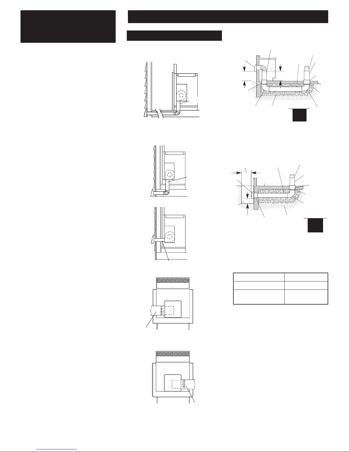
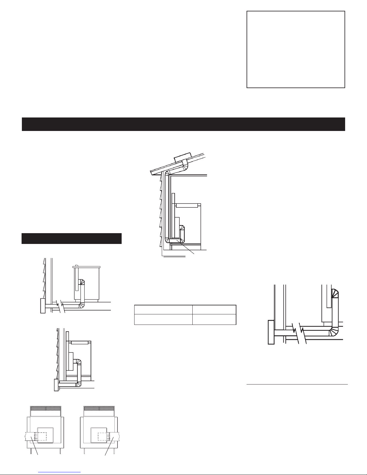
Interior-mounted vent motor
Installation requirements
Island location
Built-in cabinet locations
down vent
down vent
rear vent
left vent
right vent
Vent system installed under a
concrete slab using PVC sewer pipe.
wall
cap
6" (15.2 cm)
round PVC
coupling
6" (15.2 cm)
round PVC
sewer pipe
6" (15.2 cm) round metal vent
Tightly pack
gravel or sand
completely
around pipe.
transition
6" (15.2 cm)
round metal
vent
6" (15.2 cm)
round PVC
coupling
concrete
slab
6" (15.2 cm)
round PVC
sewer pipe
6" (15.2 cm)
round 90°
PVC sewer
pipe elbow
6" (15.2 cm)
round 90°
PVC sewer
pipe elbow
16" (40.6 cm)
maximum
12" (30.5 cm)
minimum
SBCCI
wall
cap
window
well
6" (15.2 cm)
min.
Tightly pack
gravel or sand
completely
around pipe.
transition
6" (15.2 cm)
round metal vent
6" (15.2 cm)
round PVC
coupling
6" (15.2 cm)
round sewer
pipe
6" (15.2 cm) round
90° PVC sewer
pipe elbow
concrete
slab
6" (15.2 cm)
round PVC
coupling
12" (30.5 cm)
minimum
6" (15.2 cm) round
PVC sewer pipe
Optional vent system installed under
a concrete slab into a window well.
Do not vent a gas cooktop into
a window well.
SBCCI
Seal the space between the outside of
wall cap inlet inside of PVC coupling
with caulking metal.
Maximum length of vent
system
For best performance, use no more
than three 90° elbows. If more than
one elbow is used, make sure that
there is a minimum of 24" (61 cm)
of straight vent between any two
elbows. Do not install two elbows
together. It is recommended that
you use round vent instead of
rectangular vent, especially if
elbows are required. If rectangular
vent is required, it should be
transitioned to 6" (15.2 cm) round
vent as soon as possible.
Determining the length of
system you need:
To calculate the length of system
you need, add the equivalent feet
for each vent piece that will be
needed. See example for 6"
(15.2 cm) round vent system.
Vent Length
6" (15.2 cm) round 35 feet (8.9 m)
3-1/4" x 10" 35 feet (8.9 m)
(8.3 cm x 25.4 cm)
7
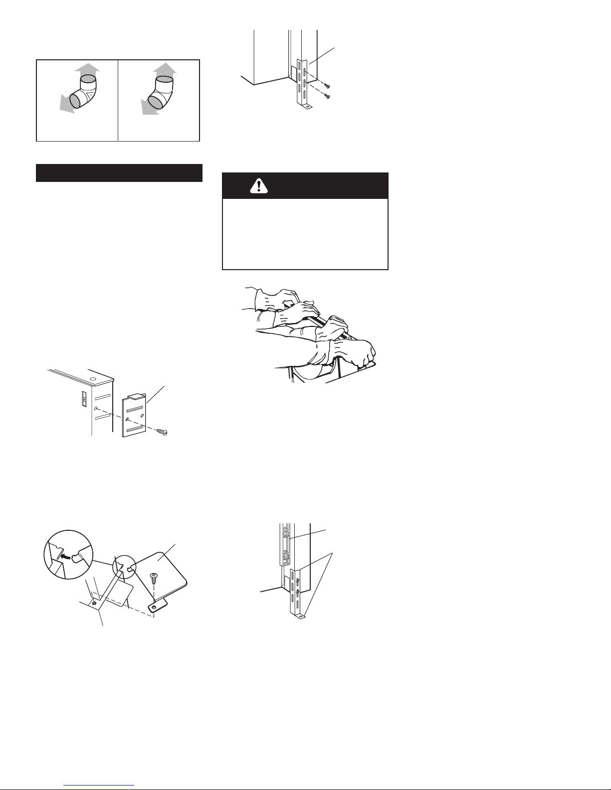
Excessive Weight Hazard
Use two or more people to move
and install downdraft vent.
Failure to do so can result in back
or other injury.
WARNING
6" (15.2 cm) round
vent system
6 ft. (1.8 m)
2 ft. (0.6 m)
90° elbows
transition
Maximum length = 35 ft. (8.9 m)
1 - wall cap = 0 ft. (0 m)
8 ft. (2.4 m) straight = 8 ft. (2.4 m)
2 - 90° elbows = 10 ft. (3 m)
Transition = 4.5 ft. (1.4 m)
Length of 6"
(15.2 cm) system = 22.5 ft. (6.8 m)
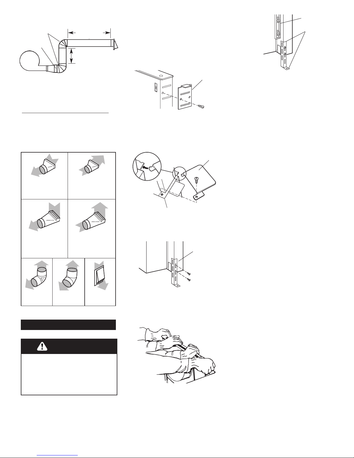
Recommended standard
fittings
3-1/4" x 10"
(8.3 cm x 25.4 cm)
to 6" (15.2 cm)
= 4.5 ft. (1.4 m)
90° elbow =
5 ft. (1.5 m)
45° elbow =
2.3 ft. (0.8 m)
6" wall cap =
0 ft. (0 m)
6" (15.2 cm) to
3-1/4" x 10"
(8.3 cm x 25.4 cm)
= 1 ft. (0.3 m)
3-1/4" x 10"
(8.3 cm x 25.4 cm)
to 6" (15.2 cm)
90° elbow =
5 ft. (1.5 m)
6" (15.2 cm) to
3-1/4" x 10"
(8.3 cm x 25.4 cm)
90° elbow =
5 ft. (1.5 m)
1. Put on gloves and safety
glasses. Place cardboard or
another form of protection on top
of a flat surface where you can
3. Attach the left side and right
side end caps to the downdraft.
Use 1 screw with each end cap.
2. Attach the left side and right
side overcounter support brackets
to the downdraft. Use 1 screw
with each bracket.
5. Carefully insert downdraft
vent into countertop cutout. Two
people are recommended to
support the weight of the
downdraft vent during lifting.
Check that downdraft vent is
parallel to side of cutout and that
mounting brackets overlap
countertop.
6. Move support legs down
against cabinet floor. Place a level
against front of downdraft vent
base and adjust until downdraft
vent is level vertically. Use a
pencil to mark the top of each leg
on downdraft vent. Then mark
location of support leg mounting
holes on cabinet floor. Remove
downdraft vent from cutout. Drill
starter holes at each mounting
screw location on cabinet floor.
Align top of legs with pencil
marks on the face of the
downdraft vent. Tighten screws in
legs.
7. Determine which direction
(down, rear, left, or right) vent
will need to run from blower vent
when installed in cabinet.
Down venting:
Downdraft vent is shipped with
blower in down venting position
so no modification is required.
Go to Step 8.
Left or right venting:
a. Remove 4 hex nuts that attach
blower box to downdraft vent
base. Remove blower box.
b. Rotate blower box 90° to left or
right so that vent blower is
repositioned in the direction
needed.
c. Reattach blower box to
downdraft vent base with 4 hex
nuts.
Rear venting:
a. Remove 4 hex nuts that attach
blower box to downdraft vent
base. Remove blower box.
b. Note how wiring cable is
installed under plastic clips
inside vent base. Then carefully
remove wiring cable from
plastic clips. Disconnect
blower wiring cable.
c. Remove 6 Phillips-head screws
attaching blower to blower box.
Remove blower.
Installation steps
over counter
support arm
4. Attach support legs to side
of downdraft vent with 2 screws
in each leg. Do not tighten
screws.
support leg
mark
level
end cap
easily assemble the downdraft
vent system. Remove parts
packages, downdraft vent and
blower box from carton and set
on protective surface. Remove all
shipping materials, tape and
protective film from downdraft
vent and blower box.
8
d. Remove screws attaching
brackets to each side of blower.
Reposition brackets on blower
as shown. Then reinstall screws.
e. Reinstall blower in blower box
with mouth of blower pointing
out open side of blower box.
Secure blower to blower box
with 6 Phillips-head screws.
NOTE: Square metal frame
attached to mouth of blower must
be installed for proper operation.
f. Attach metal cover from parts
bag over down-venting knockout
in blower box. Remove rear
knockout cover on back of vent
base.
g. Reconnect blower wiring cable.
Secure wiring cable in 2 black
plastic clips inside vent
base.The wiring cable must be
properly secured in the 2 clips
(see step b.) Reattach blower
box to downdraft vent base with
4 hex nuts.
bracket for
rear venting
8. Attach backdraft damper
over blower box knockout with 2
Phillips-head screws.
9. Remove the 2 Phillips-head
screws attaching the wiring box
cover. Determine which direction
(rear or down) electrical connection
will need to run from appliance
wiring box. Remove rear or bottom
knockout and install conduit
connector.
Excessive Weight Hazard
Use two or more people to move
and install downdraft vent.
Failure to do so can result in back
or other injury.
WARNING
10. Insert downdraft vent
into countertop cutout. Two people
are recommended to support the
weight of the downdraft vent
during lifting. Position downdraft
vent so it is centered in cutout and
parallel to edge of cutout. Check
that downdraft vent is level
vertically. Then fasten lower
support legs to cabinet floor with
screws.
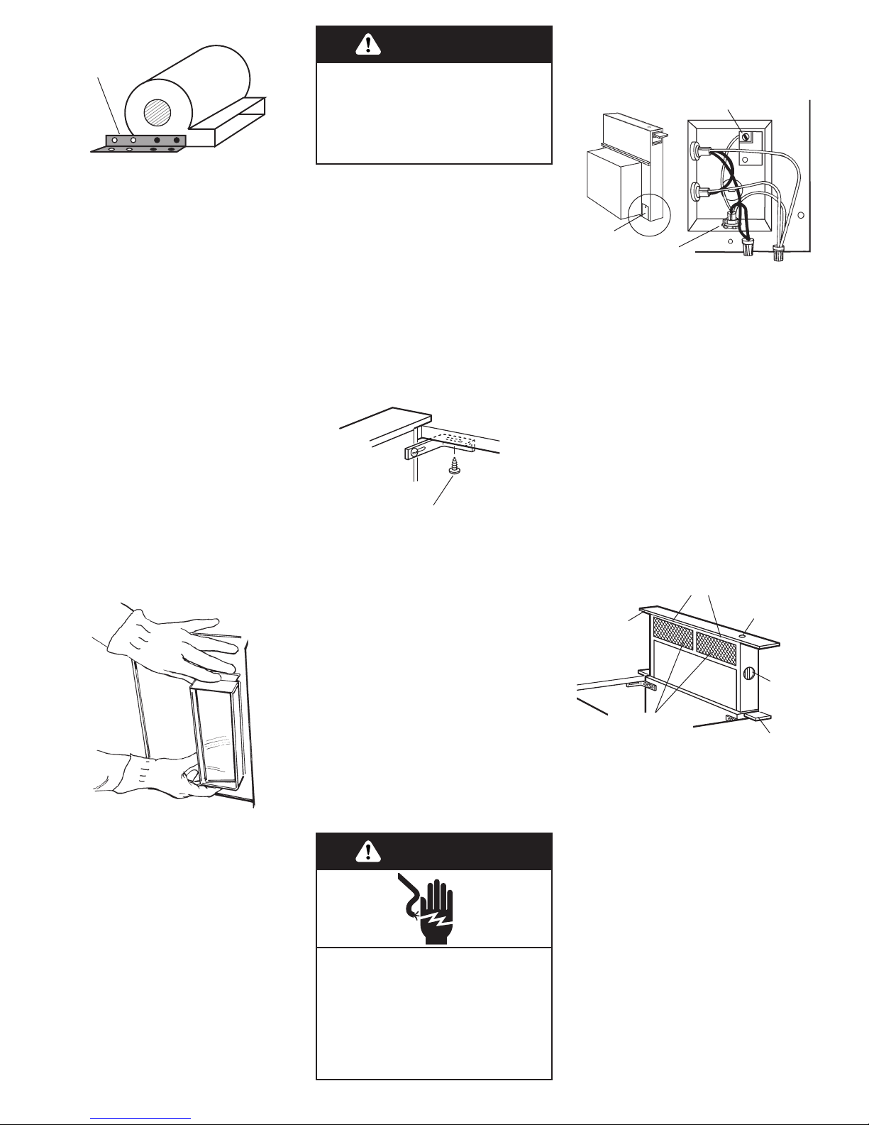
11. Attach one undercounter
bracket on front upper right
corner of downdraft vent with slot
over vent mounting hole and
flange against countertop. Attach
other bracket to left side of
downdraft vent. Carefully drill
starter holes through
undercounter mounting brackets
into underside of countertop.
Insert appropriate length screws
into holes and tighten brackets to
countertop.
When attaching undercounter bracket
to underside of countertop, make
sure that the screw length will not go
through countertop when tightened.
Electrical Shock Hazard
Disconnect power before
servicing.
Connect ground wire to green
ground screw in terminal box.
Failure to do so can result in
death or electrical shock.
WARNING
12. Disconnect power.
13. Remove required
knockout and install conduit
connector. Feed the power supply
cable through the conduit
connector and into the wiring box.
Connect the white wires together
with a twist-on wire connector.
Connect the black wires together
with a twist-on wire connector.
Attach the green (or green and
yellow) ground wire to eyelet with
green ground screw. Tighten the
conduit connector clamp screws.
Replace the wiring box cover.
14. Reconnect power.
ON/OFF
button
blower
control
knob
end cap
top trim
filter or filters
depending on
model
microswitches behind filters.
wiring
box
green
ground
screw
conduit
connector
15. Push and hold for a few
seconds the button on the top of
the downdraft vent. Retractable
section of downdraft vent will rise
and blower will start. Position the
top trim over the retractable
section and snap trim into place.
9
17. Connect vent system to
blower. Vent system must end with
a wall or roof cap. Use duct tape to
seal all joints.
18. Install cooktop according
to manufacturer’s instructions.
Check that rear of cooktop overlaps
edge of retractable downdraft vent
by 3/8" (9.5 mm).
To get the most efficient use
from your new retractable
downdraft vent, read the Use
and Care Information section
on page 12.
Keep Installation Instructions
and Use and Care
Information close by for
easy reference.
Island location
Built-in cabinet location
Roof venting
KIRD and YKIRD
MODELS ONLY
NOTE: Exterior-mounted vent
motor installations require exterior
blower system, Model No.
KPEC992M [900 cfm (25.5 m3/m)],
available from your dealer or
authorized parts supplier.
IMPORTANT: Exterior blower
Model No. KPEU722M [1200 cfm
(34.0 m3/3)] cannot be used with
this retractable downdraft vent
system.
10" (25.4 cm)
round vent
Maximum length of vent
system
For best performance, use no more
than three 90° elbows. If more than
one elbow is used, make sure that
there is a minimum of 24 inches
(61 cm) of straight vent between
any two elbows. Do not install two
elbows together.
It is recommended that you use
round vent instead of rectangular
vent, especially if elbows are
required. If rectangular vent is
required, it should be transitioned
to 10" (25.4 cm) round vent as
soon as possible.
Determining the length of system
you need:
To calculate the length of system
you need, add the equivalent feet
for each duct piece that will be
needed. See example for 10"
(25.4 cm) round vent system.
NOTE:The exterior-mounted vent
motor requires a separate wiring
cable that should be installed at
the same time the vent work is
installed.
10" (25.4 cm) round
vent system
2 - 90 elbows = 10 ft. (3.05 m)
10 ft. (3 m) straight = 10 ft. (3.05 m)
Length of 10"
(25.4 cm) system = 20 ft. (6.1 m)
Maximum length = 40 ft. (12.2 m)
left vent
right vent
Installation requirements
Exterior-mounted vent motor
Vent Length
10" (25.4 cm) round 40 ft. (12.2 m)
Vent length is given as a general
reference only. For a longer vent
run, or smaller vent system,
contact a qualified and trained
vent installer. Check with local
codes for makeup air
requirements, if any.
16. Turn the control knob on
side of vent to check the
operation and speed of blower.
If blower does not operate:
• Check that filter or filters are
pressed in as far as they will go.
• Check that circuit breaker is not
tripped or house fuse blown.
• Disconnect power. Check that
wire connections have been
made correctly.
• Reconnect power.
Built-in cabinet location
90° elbow =
5 ft. (1.5 m)
45° elbow =
2.5 ft. (0.8 m)
Recommended standard
fittings
Installation steps
1. Put on gloves and safety
glasses. Place cardboard or another
form of protection on top of a flat
surface where you can easily
assemble the downdraft vent
system. Remove parts packages,
downdraft vent and blower box
from carton. Remove all shipping
materials, tape and protective film
from downdraft vent and blower
box.
4. Attach support legs to side of
downdraft vent with two screws in
each leg. Do not tighten screws.
Excessive Weight Hazard
Use two or more people to move
and install downdraft vent.
Failure to do so can result in back
or other injury.
WARNING
7. Attach 10" (25.4 cm) round
vent collar plate (supplied with
exterior blower system) to front of
downdraft vent using 4 hex washer
nuts.
5. Carefully insert downdraft
vent into countertop cutout. Two
people are recommended to
support the weight of the
downdraft vent during lifting.
Check that downdraft vent is
parallel to side of cutout and that
mounting brackets rest gently on
countertop.
6. Move support legs down
against cabinet floor. Place a level
against front of downdraft vent
base and adjust position of legs
until downdraft is level vertically.
Use a pencil to mark the top of
each leg on face of downdraft vent.
Then mark location of support leg
mounting holes on cabinet floor.
Remove downdraft vent from
cutout. Drill starter holes at each
mounting screw location on
8. Remove the 2 Phillips-head
screws attaching the wiring box
cover and remove cover. Remove
either the back or bottom knockout
and install conduit connector.
NOTE: Power supply cable needed
between exterior blower assembly
and blower box is not provided.
9. Determine the location where
the exterior blower box will be
located. Cut opening in roof or wall
for vent system to exterior blower.
Install exterior blower according to
instructions supplied with the
blower kit.
Wall Installations:
• Use caulking compound between
mounting flange and wall.
Roof Installations:
• Follow standard roofing
procedures.
• The flashing sheet should be
centered over the roof opening.
• Lower edge of flashing should lie
on top of shingles and upper edge
underneath shingles.
• Seal assembly between roof, fan
and flashing with roofing mastic
to prevent leaks.
10
3. Attach the left side and right
side end caps to the downdraft.
Use 1 screw with each end cap.
2. Attach the left side and right
side overcounter support brackets
to the downdraft. Use 1 screw
with each bracket.
over counter
support arm
support leg
mark
level
end cap
cabinet floor. Align top of legs
with pencil marks on face of
downdraft vent. Tighten screws
in legs.
 Loading...