

KitchenAid KODE300E, KODE307E, KODT107E, KOSE500E, KOSE507E Installation Instructions Manual
...
INSTALLATION INSTRUCTIONS
27" (68.6 CM) AND 30" (76.2 CM) ELECTRIC
SINGLE AND DOUBLE BUILT-IN OVEN
INSTRUCTIONS D’INSTALLATION
FOUR ÉLECTRIQUE ENCASTRÉ 27" (68,6 CM) ET 30"
(76,2 CM) - SIMPLE ET DOUBLE
Table of Contents/Table des matières
BUILT-IN OVEN SAFETY...............................................................2
INSTALLATION REQUIREMENTS ................................................2
Tools and Parts ............................................................................2
Location Requirements ................................................................3
Electrical Requirements ...............................................................6
INSTALLATION INSTRUCTIONS ..................................................7
Prepare Built-In Oven...................................................................7
Remove Oven Door(s)..................................................................7
Replace Oven Door(s)..................................................................7
Positioning Oven Feet for Multiple Cabinet Cutout Heights .......8
Make Electrical Connection .......................................................13
Install Oven.................................................................................14
Install Warming Drawer Deflector Kit (Only for Ovens Installed
Above Warming Drawers) ..........................................................15
Complete Installation .................................................................16
SÉCURITÉ DU FOUR ENCASTRÉ ..............................................17
EXIGENCES D'INSTALLATION ...................................................17
Outillage et pièces......................................................................17
Exigences d'emplacement.........................................................18
Spécifications électriques ..........................................................21
INSTRUCTIONS D'INSTALLATION.............................................22
Préparation du four encastré .....................................................22
Dépose de la/des porte(s) du four .............................................22
Réinstallation de la/des porte(s) du four ....................................23
Positionnement des pieds du four pour des ouvertures
d'encastrement de hauteur différente........................................24
Raccordement électrique...........................................................28
Installation du four......................................................................29
Installation de l'ensemble de déflecteur du tiroir-réchaud
(uniquement pour les fours installés au-dessus d'un tiroir-
réchaud)......................................................................................31
Achever l’installation ..................................................................32
IMPORTANT:
Save for local electrical inspector's use.
IMPORTANT :
À conserver pour consultation par l'inspecteur local des installations électriques.
W10725670B
2
BUILT-IN OVEN SAFETY
INSTALLATION REQUIREMENTS
Tools and Parts
Gather the required tools and parts before starting installation.
Read and follow the instructions provided with any tools listed
here.
Tools Needed
■ Phillips screwdriver
■ Measuring tape
■ Hand or electric drill (for wall cabinet installations)
■ 1" (2.5 cm) drill bit (for wall cabinet installations)
■ Level
■ Flat-blade screwdriver
Parts Needed
■ UL listed or CSA approved conduit connector
■ UL listed wire connectors
■ Warming Drawer Deflector Kit (for ovens installed above a
warming drawer)
Order Part Number W10510613 for white 27" (68.6 cm) kit
Order Part Number W10531009 for black 27" (68.6 cm) kit
Order Part Number W10536338 for stainless steel 27"
(68.6 cm) kit
Order Part Number W10510614 for white 30" (76.2 cm) kit
Order Part Number W10531010 for black 30" (76.2 cm) kit
Order Part Number W10536339 for stainless steel 30"
(76.2 cm) kit
Order Part Number W10727416A for stainless steel/black 30"
(76.2 cm) kit
To order, see the “Assistance or Service” section of the Use
and Care Guide.
■ Flush Installation Kit (for Single and Double installed at flush
installation)
Order Part Number W10752684A for white 27" (68.6 cm) kit
Order Part Number W10752685A for black 27" (68.6 cm) kit
Order Part Number W10752686A for stainless steel 27"
(68.6 cm) kit
Order Part Number W10752680A for white 30" (76.2 cm) kit
Order Part Number W10752681A for black 30" (76.2 cm) kit
Order Part Number W10752683A for stainless steel 30"
(76.2 cm) kit
Order Part Number W10752682A for black/stainless steel 30"
(76.2 cm) kit
To order, see the “Assistance or Service” section of the Use
and Care Guide.
Parts Supplied
■
#8-14 x 1" screws - single ovens (2), double ovens (4)
■ #8-18 x ³⁄₈" screws - bottom vent (2)
■ #8-18 x ¹⁄₄" screws - bottom vent trim (4)
■ #8-18 x ³⁄₈" screws - double oven feet (4)
■ Bottom vent
■ Bottom vent trim
■ Rear feet - double oven (2)
■ Front feet - double oven (2)
■ Foam strip - single oven*
Check local codes. Check existing electrical supply. See
“Electrical Requirements.”
It is recommended that all electrical connections be made by a
licensed, qualified electrical installer.
*Foam strip not included with double oven.
You can be killed or seriously injured if you don't immediately
You
can be killed or seriously injured if you don't
follow
All safety messages will tell you what the potential hazard is, tell you how to reduce the chance of injury, and tell you what can
happen if the instructions are not followed.
Your safety and the safety of others are very important.
We have provided many important safety messages in this manual and on your appliance. Always read and obey all safety
messages.
This is the safety alert symbol.
This symbol alerts you to potential hazards that can kill or hurt you and others.
All safety messages will follow the safety alert symbol and either the word “DANGER” or “WARNING.”
These words mean:
follow instructions.
instructions.
DANGER
WARNING
3
Location Requirements
IMPORTANT: Observe all governing codes and ordinances.
■ Cabinet opening dimensions that are shown must be used.
Given dimensions provide minimum clearance with oven.
■ Recessed installation area must provide complete enclosure
around the recessed portion of the oven.
■ Grounded electrical supply is required. See “Electrical
Requirements” section.
■ Electrical supply junction box should be located 3" (7.6 cm)
maximum below the support surface when the oven is
installed in a wall cabinet. A 1" (2.5 cm) minimum diameter
hole should have been drilled in the right rear or left rear
corner of the support surface to pass the appliance cable
through to the junction box.
NOTE: For undercounter installation, it is recommended that
the junction box be located in the adjacent right or left
cabinet. If you are installing the junction box on rear wall
behind oven, it is recommended that the junction box be
recessed and located in the upper center of the cabinet.
■ Oven support surface must be solid, level and flush with
bottom of cabinet cutout.
■ Floor must be able to support a single oven weight of 129 lbs
(59 kg) for 27" (68.6 cm) models or 154 lbs (70 kg) for 30"
(76.2 cm) models.
■ Floor must be able to support a double oven weight of
251 lbs (114 kg) for 27" (68.6 cm) models or 288 lbs (131 kg)
for 30" (76.2 cm) models.
IMPORTANT: To avoid damage to your cabinets, check with
your builder or cabinet supplier to make sure that the
materials used will not discolor, delaminate or sustain other
damage. This oven has been designed in accordance with
the requirements of UL and CSA International and complies
with the maximum allowable wood cabinet temperatures of
194°F (90°C).
Undercounter Installation (With Cooktop Installed Above):
Ovens approved for this type of installation have an approval
label located on the top of the oven. Refer to Cutout Dimensions
For Ovens Installed Under Cooktop (separate sheet).
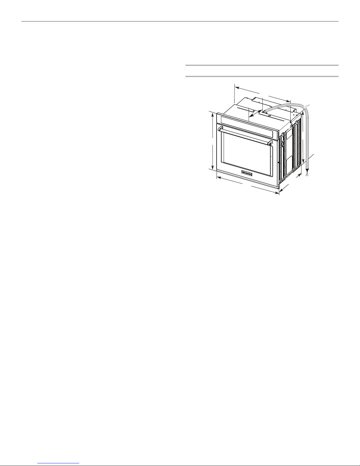
Product Dimensions - Single Ovens
27" (68.6 cm) models
A. 28¾" (72.8 cm) max. overall
height
B. 25
⁷⁄₁₆
" (64.6 cm) max. recessed
width
C. 26
³⁄₄
" (67.9 cm) recessed height
D. 23
¹⁄₄
" (59.1 cm) max. recessed
depth
E. 27" (68.6 cm) overall width
F. 12" (30.5 cm) from back of
control panel to start of strain
relief
G. 48" (121.9 cm) flexible conduit
length
30" (76.2 cm) models
A. 28¾" (72.8 cm) max. overall
height
B. 28
⁷⁄₁₆
" (72.2 cm) max. recessed
width
C. 26
³⁄₄
" (67.9 cm) recessed height
D. 23
¹⁄₄
" (59.1 cm) max. recessed
depth
E. 30" (76.2 cm) overall width
F. 12" (30.5 cm) from back of
control panel to start of strain
relief
G. 48" (121.9 cm) flexible conduit
length
B
D
E
A
C
G
F
4
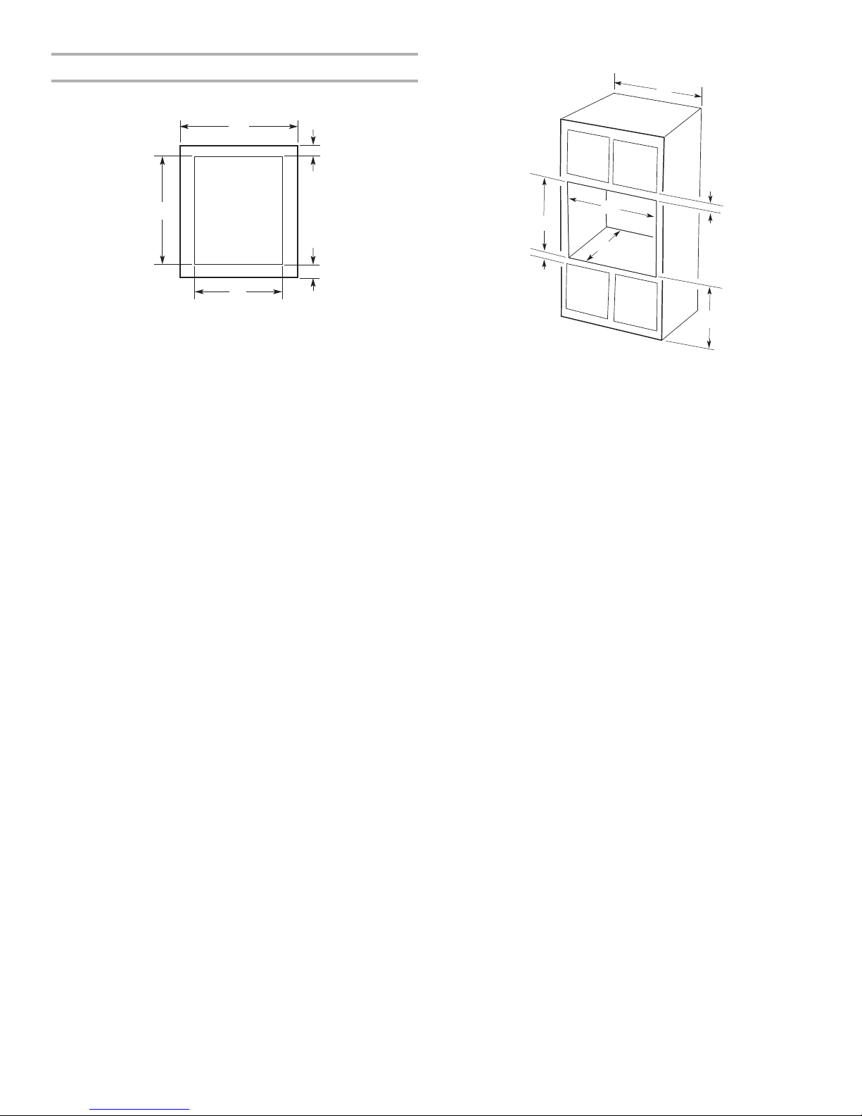
Cabinet Dimensions - Single Ovens
Single Oven Undercounter (Without Cooktop Installed Above)
Single Ovens Installed in Cabinet
*NOTE: The cutout height can be between 26¹⁵⁄₁₆" and 29⁷⁄₁₆"
(68.4 cm and 74.8 cm) for single ovens.
27" (68.6 cm) models
A. 27" (68.6 cm) min. cabinet
width
B. 1
¹⁄₂
" (3.8 cm) min. top of
cutout to underside of
countertop
C. 5
¹⁄₄
" (13.3 cm) bottom of
cutout to floor
D. 25
¹⁄₂
" (64.8 cm) cutout width
E. 28" (71.2 cm) min. cutout
height
30" (76.2 cm) models
A. 30" (76.2 cm) min. cabinet
width
B. 1
¹⁄₂
" (3.8 cm) min. top of
cutout to underside of
countertop
C. 5
¹⁄₄
" (13.3 cm) bottom of
cutout to floor
D. 28
¹⁄₂
" (72.4 cm) cutout width
E. 28" (71.2 cm) min. cutout
height
A
B
C
D
E
27" (68.6 cm) models
A. 27" (68.6 cm) min. cabinet
width
B. 1" (2.5 cm) top of cutout to
bottom of upper cabinet door
C. 32" (81.3 cm) bottom of cutout
to floor
D. 25
¹⁄₂
" (64.8 cm) cutout width
E. 1
¹⁄₂
" (3.8 cm) min. bottom of
cutout to top of cabinet door
F. 28" (71.2 cm)* recommended
cutout height
G. 24" (60.7 cm) cutout depth
30" (76.2 cm) models
A. 30" (76.2 cm) min. cabinet
width
B. 1" (2.5 cm) top of cutout to
bottom of upper cabinet door
C. 32" (81.3 cm) bottom of
cutout to floor
D. 28
¹⁄₂
" (72.4 cm) cutout width
E. 1
¹⁄₂
" (3.8 cm) min. bottom of
cutout to top of cabinet door
F. 28" (71.2 cm)* recommended
cutout height
G. 24" (60.7 cm) cutout depth
F
E
B
C
A
D
G
5
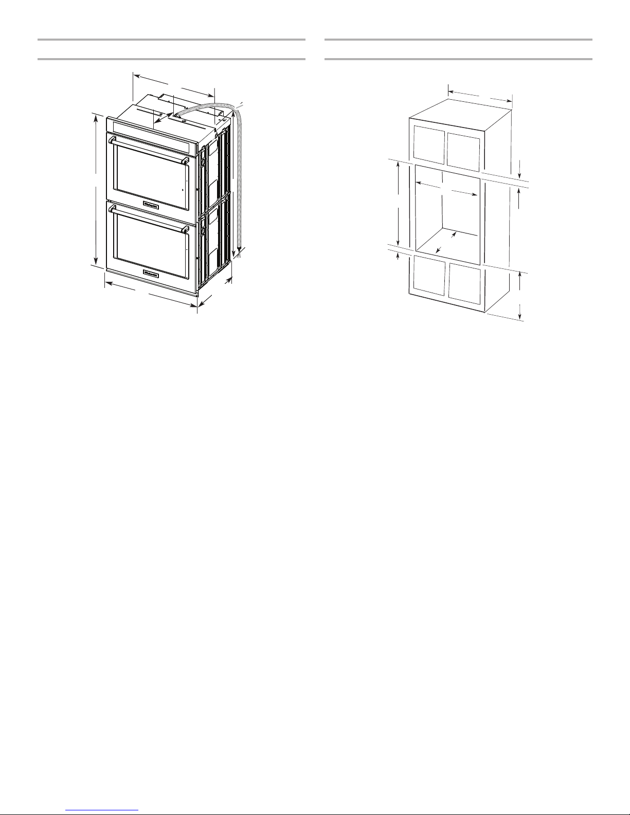
Product Dimensions - Double Ovens Cabinet Dimensions - Double Ovens
Double Ovens Installed in Cabinet
*NOTE: The cutout height can be between 48⁷⁄₈" and 52³⁄₁₆"
(124.1 cm and 132.6 cm) for double ovens.
27" (68.6 cm) models
A. 51
³⁄₁₆
" (130.0 cm) max. overall
height
B. 25
⁷⁄₁₆
" (64.6 cm) max. recessed
width
C. 48
¹³⁄₁₆
" (124.0 cm) recessed
height
D. 23
¹⁄₄
" (59.1 cm) max. recessed
depth
E. 27" (68.6 cm) overall width
F. 12" (30.5 cm) from back of
control panel to start of strain
relief
G. 66" (167.6 cm) flexible conduit
length
30" (76.2 cm) models
A. 51
³⁄₁₆
" (130.0 cm) max. overall
height
B. 28
⁷⁄₁₆
" (72.2 cm) max. recessed
width
C. 48
¹³⁄₁₆
" (124.0 cm) recessed
height
D. 23
¹⁄₄
" (59.1 cm) max. recessed
depth
E. 30" (76.2 cm) overall width
F. 12" (30.5 cm) from back of
control panel to start of strain
relief
G. 66" (167.6 cm) flexible conduit
length
C
B
A
E
D
G
F
27" (68.6 cm) models
A. 27" (68.6 cm) min. cabinet
width
B. 1" (2.5 cm) top of cutout to
bottom of upper cabinet door
C. 14
³⁄₄
" (37.5 cm) bottom of
cutout to floor is
recommended.
4"-14
³⁄₄
" (10.2-37.5 cm)
bottom of cutout to floor is
acceptable.
D. 25
¹⁄₂
" (64.8 cm) cutout width
E. 1
¹⁄₂
" (3.8 cm) min. bottom of
cutout to top of cabinet door
F. 50
¹⁄₄
" (127.6 cm)*
recommended cutout height
G. 24" (60.7 cm) cutout depth
30" (76.2 cm) models
A. 30" (76.2 cm) min. cabinet
width
B. 1" (2.5 cm) top of cutout to
bottom of upper cabinet door
C. 14
³⁄₄
" (37.5 cm) bottom of
cutout to floor is
recommended.
4"-14
³⁄₄
" (10.2-37.5 cm) bottom
of cutout to floor is acceptable.
D. 28
¹⁄₂
" (72.4 cm) cutout width
E. 1
¹⁄₂
" (3.8 cm) min. bottom of
cutout to top of cabinet door
F. 50
¹⁄₄
" (127.6 cm)*
recommended cutout height
G. 24" (60.7 cm) cutout depth
F
E
A
D
G
B
C
 Loading...