


KitchenAid KFDC500JSS, KFDC500JBK, KFDC500JIB, KFDC500JMB, KFDC500JMH Installation Instructions
...INSTALLATION INSTRUCTIONS
Commercial-Style Dual Fuel Ranges
30" (76.2 cm), 36" (91.4 cm), and 48" (121.9 cm)
For residential use only
INSTRUCTIONS D’INSTALLATION
Cuisinière à double combustible de style commercial de
30 po (76,2 cm), 36 po (91,4 cm) et 48 po (121,9 cm)
Pour utilisation résidentielle uniquement
Table of Contents/Table des matières
RANGE SAFETY.............................................................................. |
2 |
INSTALLATION REQUIREMENTS................................................. |
4 |
Tools and Parts............................................................................. |
4 |
Location Requirements................................................................. |
5 |
Electrical Requirements: U.S.A. Only........................................... |
7 |
Electrical Requirements: Canada Only......................................... |
7 |
Gas Supply Requirements............................................................ |
7 |
INSTALLATION INSTRUCTIONS................................................... |
9 |
Unpack the Range........................................................................ |
9 |
Remove Door................................................................................ |
9 |
Install Anti-Tip Bracket............................................................... |
10 |
Make Gas Connection................................................................ |
11 |
Verify Anti-Tip Bracket Location................................................. |
12 |
Install Griddle Tray...................................................................... |
12 |
Electronic Ignition System.......................................................... |
12 |
Level Range................................................................................ |
13 |
Install Kick Plate.......................................................................... |
13 |
Complete Installation.................................................................. |
13 |
GAS CONVERSIONS.................................................................... |
14 |
Propane Gas Conversion........................................................... |
14 |
Natural Gas Conversion............................................................. |
17 |
SÉCURITÉ DE LA CUISINIÈRE.................................................... |
21 |
EXIGENCES D’INSTALLATION.................................................... |
23 |
Outils et pièces........................................................................... |
23 |
Exigences d’emplacement......................................................... |
24 |
Spécifications électriques : É.-U. seulement............................. |
26 |
Spécifications électriques : Canada seulement......................... |
27 |
Spécifications de l’alimentation en gaz...................................... |
27 |
INSTRUCTIONS D’INSTALLATION............................................. |
29 |
Déballage de la cuisinière........................................................... |
29 |
Retirer la porte............................................................................ |
29 |
Installation de la bride antibasculement..................................... |
30 |
Raccordement au gaz................................................................ |
31 |
Vérification de l’emplacement de la bride antibasculement...... |
32 |
Installer le plateau d’égouttement.............................................. |
32 |
Système d’allumage électronique.............................................. |
32 |
Ajustement de l’aplomb de la cuisinière.................................... |
33 |
Installer la plinthe........................................................................ |
33 |
Terminer l’installation.................................................................. |
33 |
CONVERSIONS POUR CHANGEMENT DE GAZ....................... |
34 |
Conversion pour l’alimentation au propane............................... |
34 |
Conversion au gaz naturel.......................................................... |
37 |
IMPORTANT:
Save for local electrical inspector’s use.
Installer: Leave installation instructions with the homeowner.
Homeowner: Keep installation instructions for future reference.
IMPORTANT :
Conserver ces instructions à l’usage de l’inspecteur des installations électriques local. Installateur : Remettre les instructions d’installation au propriétaire.
Propriétaire : Conserver les instructions d’installation pour référence ultérieure.
W11114334A |
www.kitchenaid.com (U.S.A.) www.kitchenaid.ca (Canada) |

RANGE SAFETY
WARNING: If the information in these instructions is not followed exactly, a fire or explosion may result causing property damage, personal injury or death.
–Do not store or use gasoline or other flammable vapors and liquids in the vicinity of this or any other appliance.
–WHAT TO DO IF YOU SMELL GAS:
•Do not try to light any appliance.
•Do not touch any electrical switch.
•Do not use any phone in your building.
•Immediately call your gas supplier from a neighbor's phone. Follow the gas supplier's instructions.
•If you cannot reach your gas supplier, call the fire department.
–Installation and service must be performed by a qualified installer, service agency or the gas supplier.
WARNING: Gas leaks cannot always be detected by smell.
Gas suppliers recommend that you use a gas detector approved by UL or CSA.
For more information, contact your gas supplier.
If a gas leak is detected, follow the “What to do if you smell gas” instructions.
2
IMPORTANT: Do not install a ventilation system that blows air downward toward this gas cooking appliance. This type of ventilation system may cause ignition and combustion problems with this gas cooking appliance resulting in personal injury or unintended operation.
In the State of Massachusetts, the following installation instructions apply:
■Installations and repairs must be performed by a qualified or licensed contractor, plumber, or gas fitter qualified or licensed by the State of Massachusetts.
■Acceptable Shut-off Devices: Gas Cocks and Ball Valves installed for use shall be listed.
■A flexible gas connector, when used, must not exceed 4 feet (121.9 cm).
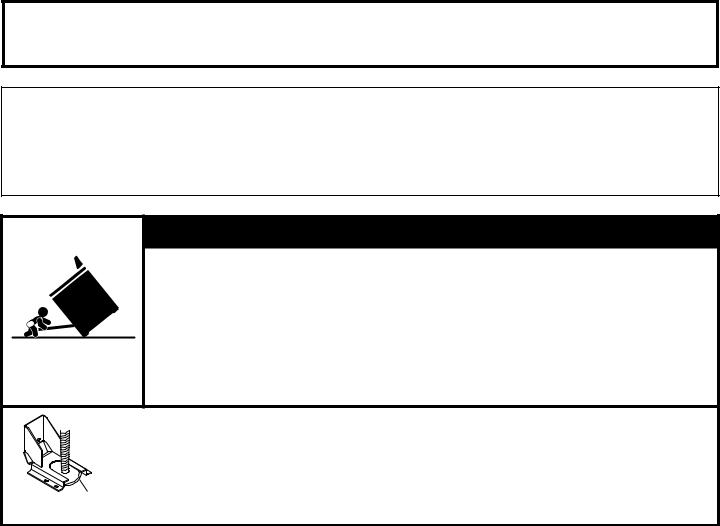
 WARNING
Tip Over Hazard A child or adult can tip the range and be killed.
Install anti-tip bracket to floor or wall per installation instructions.
Slide range back so rear range foot is engaged in the slot of the anti-tip bracket. Re-engage the anti-tip bracket if the range is moved.
Do not operate range without anti-tip bracket installed and engaged.
Failure to follow these instructions can result in death or serious burns to children and adults.
Anti-Tip
 Bracket
Range Foot
To verify the anti-tip bracket is installed and engaged:
•Slide range forward.
•Look for the anti-tip bracket securely attached to floor or wall.
•Slide range back so rear range foot is under anti-tip bracket.
•See installation instructions for details.
3
INSTALLATION REQUIREMENTS
Tools and Parts
Gather the required tools and parts before starting installation. Read and follow the instructions provided with any tools listed here.
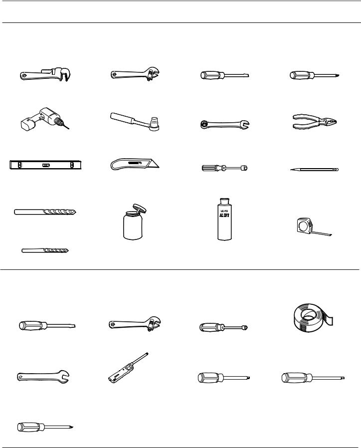
Tools Needed
Pipe wrench |
Adjustable wrench or |
1/8" x 41/4" (3 mm x 100 mm) |
#2 Phillips screwdriver |
|
5/8" (16 mm) wrench |
flat blade screwdriver |
|
|
|
|
|
Drill |
3/8" (9.5 mm) drive ratchet |
15/16" (24 mm) |
Pliers |
|
|
combination wrench |
|
|
|
|
|
Level |
Tubing cutter |
1/4" (6.4 mm), 3/8" (9.5 mm), |
Marker or pencil |
|
|
5/16" (7.9 mm) nut drivers |
|
|
|
|
|
3/16" (4.8 mm) carbide tip masonry bit
Pipe-joint compound |
Noncorrosive leak-detection |
Tape measure |
resistant to propane gas |
solution |
|
1/8" (3.2 mm) drill bit
For Propane/Natural Gas Conversions
Large flat-blade screwdriver |
Adjustable wrench |
7 mm Nut Driver |
Masking tape |
|
|
|
|
1/2" (1.3 cm) open end |
Lighter |
T-20 Torx Driver |
#1 Square Drive |
wrench |
|
|
|
|
|
|
|
#2 Phillips Screwdriver
4
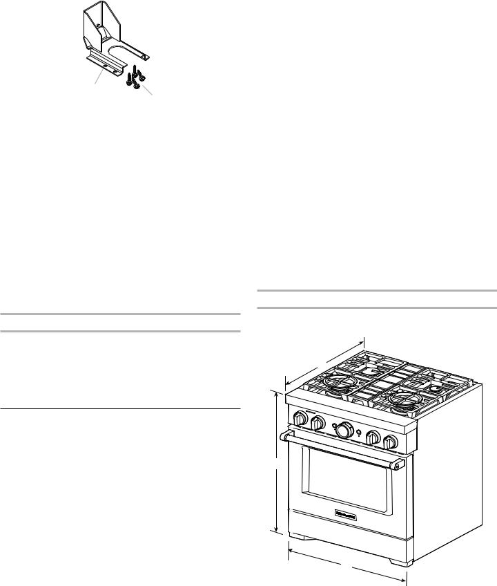
Parts Supplied
Check that all parts are included. ■■ Anti-tip bracket kit
A
B
A.Anti-tip bracket
B.#8-18 x 1" (2.5 cm) Phillips head screws (4)
NOTE: Anti-tip bracket must be securely mounted to subfloor. Thickness of flooring may require longer screws to anchor bracket to subfloor. Longer screws are available from your local hardware store. See the “Install Anti-Tip Bracket” section.
■■ Burner grates ■■ Burner caps
■■ Griddle drip tray (on griddle models)
Parts Needed
■■ All models must be installed with a backguard if installing at zero clearance to a combustible back wall surface such as drywall. See “Cabinet Dimensions” in the “Location Requirements” section for installation requirements.
Check local codes and consult gas supplier. Check existing gas supply and electrical supply. See the “Electrical Requirements” and “Gas Supply Requirements” sections.
It is recommended that all electrical connections be made by a licensed, qualified electrical installer.
High Altitude Conversion
To convert the range for elevations above 6,560 ft (2000 m), order a High Altitude Conversion Kit.
■■ High Altitude Kit W11238044
NOTE: Both propane and natural gas conversions are included in the high altitude kit.
To order, see the “Assistance or Service” section of the Use and Care Guide.
Location Requirements
IMPORTANT: Observe all governing codes and ordinances. Do not obstruct flow of combustion and ventilation air.
■■ It is the installer’s responsibility to comply with installation clearances specified on the model/serial/rating plate. The model/serial/rating plate is located under the console on the right-hand side.
■■ It is recommended that a 600 CFM (17.0 m3/hr) or larger range hood be installed above the range.
■■ Follow the range hood or microwave hood combination installation instructions for dimensional clearances above the cooktop surface.
■■ Recessed installations must provide complete enclosure of the sides and rear of the range.
■■ All openings in the wall or floor where range is to be installed must be sealed.
■■ Do not seal the range to the side cabinets.
■■ Cabinet opening dimensions that are shown must be used. Given dimensions are minimum clearances.
■■ The anti-tip bracket must be installed. To install the anti-tip bracket shipped with the range, see the “Install Anti-Tip Bracket” section.
■■ Grounded electrical supply is required. See the “Electrical Requirements” section.
■■ Proper gas supply connection must be available. See the “Gas Supply Requirements” section.
■■ Contact a qualified floor covering installer to check that the floor covering can withstand at least 200°F (93°C). Use an insulated pad or 1/4" (6.4 mm) plywood over carpet and under range if installing range over carpeting.
IMPORTANT: To avoid damage to your cabinets, check with your builder or cabinet supplier to make sure that the materials used will not discolor, delaminate, or sustain other damage. This oven has been designed in accordance with the requirements of UL and CSA International and complies with the maximum allowable wood cabinet temperatures of 194°F (90°C).
Mobile Home - Additional Installation Requirements
The installation of this range must conform to the Manufactured Home Construction and Safety Standard, Title 24 CFR,
Part 3280 (formerly the Federal Standard for Mobile Home Construction and Safety, Title 24, HUD Part 280). When such standard is not applicable, use the Standard for Manufactured Home Installations, ANSI A225.1/NFPA 501A or local codes.
In Canada, the installation of this range must conform with the current standards CAN/CSA-A240-latest edition or with local codes.
Mobile Home Installations Require:
■■ When this range is installed in a mobile home, it must be secured to the floor during transit. Any method of securing the range is adequate as long as it conforms to the
standards listed above.
Product Dimensions
NOTE: Cooktop features may differ.
30" (76.2 cm) models
B
 D
D
C
A. 273/4" (70.5 cm) depth with control panel (See NOTE.) B. 36" (91.4 cm) range height when sitting on the wheels C. 297/8 " (75.7 cm) width
D. Model/serial/rating plate location/SAID label (located on front side panel)
5
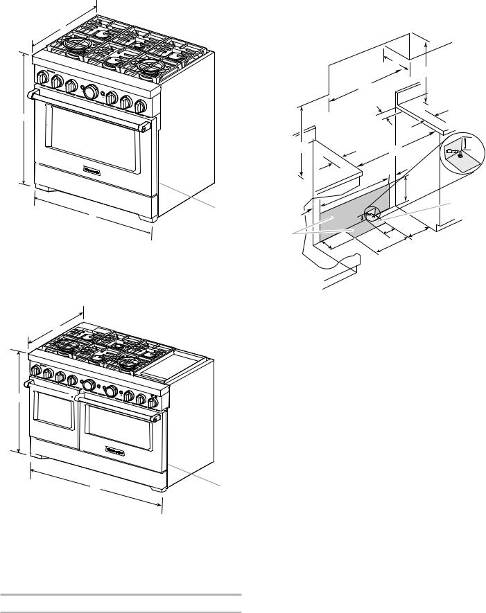
36" (91.4 cm) models
A
B
D
C
A.273⁄4" (70.5 cm) depth with control panel (See NOTE.)
B.36" (91.4 cm) range height when sitting on the wheels
C.357⁄8" (91.1 cm) width
D.Model/serial/rating plate location/SAID label (located on front side panel)
48" (121.9 cm) models
A 
B 


C
 D
D
A.273⁄4" (70.5 cm) depth with control panel (See NOTE.)
B.36" (91.4 cm) range height when sitting on the wheels
C.477⁄8" (121.6 cm) width
D.Model/serial/rating plate location/SAID label (located on front side panel)
NOTE: When installed in a 24" (61.0 cm) base cabinet with 25" (63.5 cm) countertop; front of oven door protrudes 3" (7.6 cm) beyond 24" (61.0 cm) base cabinet.
Cabinet Requirements
Cabinet opening dimensions shown are for 25" (64.0 cm) countertop depth, 24" (61.0 cm) base cabinet depth, and 36" (91.4 cm) countertop height. Dimensions must be met in order to ensure a flush fit to back wall.
IMPORTANT: If installing a range hood or microwave hood combination above the cooking surface, follow the range hood or microwave hood combination installation instructions for dimensional clearances above the cooking surface.
|
C |
D ** |
|
|
|
B |
|
|
O*** |
|
F |
A |
E |
J |
|
||
|
|
|
F |
|
|
|
|
I |
G |
|
H |
|
|
|
|
|
Gas |
|
I |
|
installation |
|
|
area |
|
|
J |
|
|
Electrical |
|
L |
N |
installation |
K |
||
area* |
|
M |
|
A.18" (45.7 cm) upper cabinet to countertop
B.30" (76.2 cm) model: 30" (76.2 cm) min. upper cabinet width 36" (91.4 cm) model: 36" (91.4 cm) min. upper cabinet width 48" (121.9 cm) model: 48" (121.9 cm) min. upper cabinet width
C.13" (33 cm) max. upper cabinet depth
D.For minimum clearance to top of range.**
E.30" (76.2 cm) on 30" (76.2 cm) models 36" (91.4 cm) on 36" (91.4 cm) models 48" (121.9 cm) on 48" (121.9 cm) models
F.12" (30.4 cm) min. clearance from both sides of range to side wall or other combustible material
G.15" (38.1 cm)
H.22" (55.9 cm) on 30" (76.2 cm) models 28" (71.1 cm) on 36" (91.4 cm) models 40" (101.6 cm) on 48" (121.9 cm) models
I.4" (10.1 cm)
J.3" (7.6 cm)
K.5" (12.7 cm)
L.6" (15.2 cm) on 30" (76.2 cm) models 14" (35.5 cm) on 36" (91.4 cm) models 24" (61.0 cm) on 48" (121.9 cm) models
M.101/2" (26.7 cm)
N.6" (15.2 cm)
O.6" (15.2 cm)***
**Minimum Clearances
30" (76.2 cm) models: 42" (106.7 cm) minimum clearance between the top of the cooking platform and the bottom of a combustible surface
36" (91.4 cm) models: 58" (147.3 cm) minimum clearance between the top of the cooking platform and the bottom of a combustible surface
48" (121.9 cm) models: 58" (147.3 cm) minimum clearance between the top of the cooking platform and the bottom of a combustible surface
***If the surface of the back wall is constructed of a combustible material and a backguard is not installed, a 6" (15.2 cm) minimum clearance is required for all models.
6

Electrical Requirements:
U.S.A. Only
If codes permit and a separate ground wire is used, it is recommended that a qualified electrical installer determine
that the ground path and wire gauge are in accordance with local codes.
If codes permit and a separate ground wire is used, it is recommended that a qualified electrician determine that the ground path is adequate.
Do not use an extension cord.
Be sure that the electrical connection and wire size are adequate and in conformance with the National Electrical Code, ANSI/ NFPA 70 — latest edition — and all local codes and ordinances.
A copy of the above code standards can be obtained from:
National Fire Protection Association
1 Batterymarch Park
Quincy, MA 02169-7471
WARNING: Improper connection of the equipment-grounding conductor can result in a risk of electric shock. Check with a qualified electrician or service technician if you are in doubt as to whether the appliance is properly grounded. Do not modify the power supply cord plug. If it will not fit the outlet, have a proper outlet installed by a qualified electrician.
Electrical Connection
To properly install your range, you must determine the type of electrical connection you will be using and follow the instructions provided for it here.
■■ Range must be connected to the proper electrical voltage and frequency as specified on the model/serial/rating plate. The model/serial/rating plate is located under the console on the right-hand side. Refer to the illustrations in “Product Dimensions” in the “Location Requirements” section.
■■ This range is manufactured with a 4-wire power supply cord. ■■ A circuit breaker is recommended.
■■ Wire sizes and connections must conform with the rating of the range.
NOTE: If your home does not have a 4-wire system, consult your local qualified electrician.
Electrical Requirements:
Canada Only
 WARNING
Electrical Shock Hazard Electrically ground range.
Failure to do so can result in death, fire, or electrical shock.
If codes permit and a separate ground wire is used, it is recommended that a qualified electrical installer determine
that the ground path and wire gauge are in accordance with local codes.
Be sure that the electrical connection and wire size are adequate and in conformance with the CSA Standard C22.1, Canadian Electrical Code, Part 1 — latest edition — and all local codes and ordinances.
A copy of the above code standards can be obtained from:
Canadian Standards Association
178 Rexdale Blvd.
Toronto, ON M9W 1R3 CANADA
■■ Check with a qualified electrical installer if you are not sure the range is properly grounded.
■■ When a 4-wire, single-phase 250 V, 60 Hz, AC-only electrical supply is available, a 40 A minimum circuit protection is required on 30" (76.2 cm) and 36" (91.4 cm) ranges and a 50 A minimum circuit protection is required on 48"
(121.9 cm) ranges, fused on both sides of the line. ■■ A time-delay fuse or circuit breaker is recommended.
■■ This range is equipped with a CSA International Certified Power Cord intended to be plugged into a standard 14-50R wall receptacle. Be sure the wall receptacle is within reach of range’s final location.
■■ Do not use an extension cord.
Gas Supply Requirements
 WARNING
Explosion Hazard
Use a new CSA International approved gas supply line. Install a shut-off valve.
Securely tighten all gas connections.
If connected to propane, have a qualified person make sure gas pressure does not exceed 14" (36 cm) water column.
Examples of a qualified person include:
licensed heating personnel,
authorized gas company personnel, and authorized service personnel.
Failure to do so can result in death, explosion, or fire.
Observe all governing codes and ordinances.
IMPORTANT: This installation must conform with all local codes and ordinances. In the absence of local codes, installation must conform with American National Standard, National Fuel Gas Code ANSI Z223.1 — latest edition — or CAN/CGA B149 — latest edition.
IMPORTANT: Range must be connected to a regulated gas supply.
IMPORTANT: Leak testing of the range must be conducted according to the manufacturer’s instructions.
7
Type of Gas
Natural Gas:
This range is factory set for use with Natural gas. The model/ serial/rating plate, located under the console on the right-hand side, has information on the types of gas that can be used. If the types of gas listed do not include the type of gas available, check with the local gas supplier.
Propane Gas conversion:
Conversion must be done by a qualified service technician.
No attempt shall be made to convert the range from the gas specified on the model/serial/rating plate for use with a different gas without consulting the serving gas supplier. To convert to Propane gas, use the Propane gas conversion kit provided with your range and see the “Gas Conversions” section. The parts for this kit are in the package containing literature supplied with the range.
Gas Supply Line
■■ Provide a gas supply line of 3/4" (1.9 cm) rigid pipe to the range location. A smaller size pipe on longer runs may result in insufficient gas supply. With Propane gas, piping or tubing size can be 1/2" (1.3 cm) minimum. Usually, Propane gas suppliers determine the size and materials used in the system.
NOTE: Pipe-joint compounds that resist the action of Propane gas must be used. Do not use TEFLON®† tape.
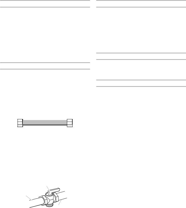
Flexible metal appliance connector:
■■ If local codes permit, a new CSA design-certified, 4-5 ft (122-152 cm) long, 5/8" (1.6 cm) or 3/4" (1.9 cm) I.D., flexible metal appliance connector may be used for connecting the range to the gas supply line.
■■ A 1/2" (1.3 cm) male pipe thread is needed for connection to the female pipe threads of the inlet to the appliance pressure regulator.
■■ Do not kink or damage the flexible metal tubing when moving the range.
IMPORTANT: All connections must be wrench-tightened. Do not make connections to the gas regulator too tight. Making the connections too tight may crack the regulator and cause a gas leak. Do not allow the regulator to turn or move when tightening fittings.
■■ Must include a shut-off valve:
Install a manual gas line shut-off valve in an easily accessible location. Do not block access to shut-off valve. The valve is for turning on or shutting off gas to the range.
B
A
C
A.Gas supply line
B.Shut-off valve open position
C.To range
Gas Pressure Regulator
The gas pressure regulator supplied with this range must be used. The inlet pressure to the regulator should be as follows for proper operation:
Natural Gas:
Minimum pressure: 6" (15.2 cm) WCP Maximum pressure: 14" (35.6 cm) WCP
Propane Gas:
Minimum pressure: 11" (27.9 cm) WCP Maximum pressure: 14" (35.6 cm) WCP
Contact local gas supplier if you are not sure about the inlet pressure.
Burner Input Rating — Altitude
Input ratings shown on the model/serial/rating plate are for elevations up to 2,000 ft (609.6 m).
For elevations above 2,000 ft (609.6 m), ratings need to be reduced at a rate of 4% for each 1,000 ft (304.8 m) above sea level (not applicable for Canada).
Gas Supply Pressure Testing
Gas supply pressure for testing regulator must be at least 1" (2.5 cm) water column pressure above the manifold pressure shown on the model/serial/rating plate.
Line pressure testing above 1/2 psi (3.5 kPa) gauge (14" [35.6 cm] WCP)
The range and its individual shut-off valve must be disconnected from the gas supply piping system during any pressure testing of that system at test pressures in excess of 1/2 psi (3.5 kPa).
Line pressure testing at 1/2 psi (3.5 kPa) gauge (14" [35.6 cm] WCP) or lower
The range must be isolated from the gas supply piping system by closing its individual manual shut-off valve during any pressure testing of the gas supply piping system at test pressures equal to or less than 1/2 psi (3.5 kPa).
†®TEFLON is a registered trademark of Chemours.
8
INSTALLATION INSTRUCTIONS
Unpack the Range
 WARNING
Excessive Weight Hazard
Use two or more people to move and install range. Failure to do so can result in back or other injury.
Remove shipping materials, tape, and film from range.
Keep shipping pallet under range. Remove oven racks, and parts package from inside oven. Remove grates from top of oven.
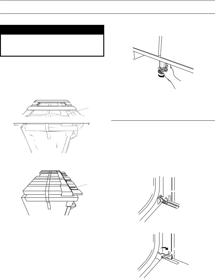
Remove Kick Plate
1.Your range will have the kick plate packaged on top of the unit.
a. Remove kick plate from top of range and grate pack.
In packaging
A
A. Kick plate
Packaging removed
A
2.For 48" (121.9 cm) models only, rotate center support counterclockwise off the pallet until it stops.
NOTE: This support is used only for shipping and is not needed for installation.
3.Lay a piece of cardboard from packaging on the floor behind range. Using two or more people, firmly grasp each side of range. Lift range up about 3" (8.0 cm) and move it back until range is off shipping pallet. Set range on cardboard to avoid damaging floor.
Remove Door
Door Removal
■■ Do not remove the side door spacers until the range is ready to install. Removing the door spacers could allow the door to shift, damaging the door latch.
■■ Do not lift or move the range by the door handle(s) or control panel.
■■ Prior to installing the range, you will need to remove the oven door(s). Prepare a surface where you will place the door(s). This surface should be flat and covered with a soft blanket, or use the corner posts from the packaging material.
 A
A
A. Kick plate |
|
b. Lay kick plate to the side to avoid scratching. |
A. Oven door hinge in the locked position |
 B
B
B. Oven door hinge in the unlocked position
9
Partially close the door to engage the door latch locks. The door will stop at this point.
Use two hands to remove and replace the oven door(s). It may be necessary to gently shift door from side to side.
A
A.Slot in the oven frame for the door hinge lock
Replace the Door
■■ To replace the oven door(s), locate the slots in the oven cavity for the hinge locks and repeat the steps above in reverse order. Make sure the door closes properly and there is no interference from the door latch. If necessary, remove the door and repeat the steps above. If power is connected to the range, open and close the door to make sure the oven light comes on and goes off appropriately.
■■ The range is equipped with leveling legs and rollers. Once the range is removed from the shipping pallet, make sure the leveling legs are not touching the floor and use the rollers
to move the range into position. Always cover the flooring surface to avoid damage to the floor. Do not roll the range directly on the floor.
Install Anti-Tip Bracket
 WARNING
Tip Over Hazard
A child or adult can tip the range and be killed.
Install anti-tip bracket to floor or wall per installation instructions.
Slide range back so rear range foot is engaged in the slot of the anti-tip bracket.
Re-engage anti-tip bracket if range is moved.
Do not operate range without anti-tip bracket installed and engaged.
Failure to follow these instructions can result in death or serious burns to children and adults.
1.Determine which mounting method to use: floor or wall.
If you have a stone or masonry floor, you can use the wall mounting method.
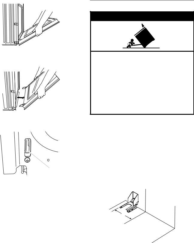
2.Determine and mark centerline of the cutout space. The mounting bracket must be installed on the left side of the cutout. Position mounting bracket in cutout as shown in the following illustration.
Measurement B:
30" (76.2 cm) ranges: 13" (33.0 cm) 36" (91.4 cm) ranges: 16" (40.6 cm) 48" (121.9 cm) ranges: 22" (55.9 cm)
Measurement C:
Optional distance from back wall. If back wall is constructed of a combustible material and a backguard is not installed, a 6" (15.2 cm) minimum clearance is required for all models.
Install anti-tip bracket accordingly.
C 

 A
A
B
A.Centerline
B.Centerline of cutout to outside edge of anti-tip bracket
C.Back wall to back of range
10
3.Drill two 1/8" (3.0 mm) holes that correspond to the bracket holes of the determined mounting method. See the following illustrations.
Floor Mounting
B
A
A.#12 x 15⁄8" (4.1 cm) screws
B.Anti-tip bracket
Wall Mounting
B
A

A.#12 x 15⁄8" (4.1 cm) screws
B.Anti-tip bracket
4.Using a Phillips screwdriver, mount anti-tip bracket to the wall or floor with the two #12 x 15⁄8" (4.1 cm) screws provided.
Depending on the thickness of your flooring, longer screws may be necessary to anchor the bracket to the subfloor. Longer screws are available from your local hardware store.
5.Move range close enough to opening to allow for electrical connections to be made. Remove shipping base, cardboard, or hardboard from under range.
6.Continue installing your range using the following installation instructions.
Make Gas Connection
 WARNING
Explosion Hazard
Use a new CSA International approved gas supply line. Install a shut-off valve.
Securely tighten all gas connections.
If connected to propane, have a qualified person make sure gas pressure does not exceed 14" (36 cm) water column.
Examples of a qualified person include:
licensed heating personnel,
authorized gas company personnel, and authorized service personnel.
Failure to do so can result in death, explosion, or fire.
1.Assemble flexible connector from gas supply pipe to pressure regulator located in the middle rear of the range.
2.Apply pipe-joint compound made for use with Propane gas to the smaller thread ends of the flexible connector adapters. (See B and G in the following illustration.)
3.Attach one adapter to the gas pressure regulator and the other adapter to the gas shut-off valve. Tighten both
adapters, being certain not to move or turn the gas pressure regulator.
4.Use a 15/16" (2.4 cm) combination wrench and an adjustable wrench to attach the flexible gas supply to the adapters. Check that connector is not kinked.
IMPORTANT: All connections must be wrench-tightened.
Do not make connections to the gas regulator too tight. Making the connections too tight may crack the regulator and cause a gas leak. Do not allow the regulator to turn or move when tightening fittings.
A B C
D
E
A.Gas pressure regulator
B.Use pipe-joint compound.
C.Adapter (must have 1/2" [1.3 cm] male pipe thread)
D.Flexible connector
H G F
E.Manual gas shut-off valve
F.1/2" (1.3 cm) or
3/4" (1.9 cm) gas pipe
G.Use pipe-joint compound.
H.Adapter
11

Complete Connection
1.Open the manual shut-off valve in the gas supply line. The valve is open when the handle is parallel to the gas pipe.
A
B
A.Closed valve
B.Open valve
2.Test all connections by brushing on an approved noncorrosive leak-detection solution. If bubbles appear, a leak is indicated. Correct any leak found.
3.Remove range burner caps, and grates from parts package. Place burner caps on burner bases. Place grates over burners and caps.
4.Check that the range is plugged into the appropriate grounded outlet. (See the “Electrical Requirements” section.)
5.Turn on power supply. For further information, please refer to the user instructions located in the Use and Care Guide.
Verify Anti-Tip Bracket Location
1.Using a 5/16" (7.9 mm) socket or wrench, turn all four leveling rods one full turn to raise the range and provide enough clearance for the rear leveling leg to slide into the anti-tip bracket.
2.Move range into its final location, making sure rear leveling leg slides into anti-tip bracket.
3.Use a flashlight to look underneath the bottom of the range and visually check that the rear range foot is inserted into the slot of the anti-tip bracket.
Install Griddle Tray
(On griddle models)
The griddle is factory installed.
1.Place drip tray in the well at the front of the griddle. Slide tray toward the back until it stops.
A
B
Electronic Ignition System
Install Burner Caps
Place burner caps on top of burner. If burner caps are not properly positioned, surface burners will not light.
Burner
A
A. Incorrect
B. Correct
B
Initial Lighting and Gas Flame Adjustments
Range burners use electronic igniters in place of standing pilots. When the Range Control Knob is turned to any position, the system creates a spark to light the burner. This sparking continues until the flame is lit or the knob is turned to OFF.
NOTE: The first time igniting the burners will take longer. This allows the gas to reach the burners during the first use.
Check Operation of Range Burners
Push in and turn each Control Knob to .
NOTE: You will hear a clicking sound while the line clears.
The surface burners and grill flames should light within
4 seconds. The first time a burner is lit, it may take longer than 4 seconds to light because of air in the gas line.
After verifying the proper burner operation, turn the Control Knobs to OFF.
If burners do not light properly:
■■ Turn Range Control Knob to OFF.
■■ Check that the range is plugged in and the circuit breaker has not tripped or the fuse has not blown.
■■ Check that the gas shut-off valves are set to the open position.
■■ Check that burner caps are properly positioned on burner bases.
Repeat startup. If a burner does not light at this point, contact your dealer or authorized service company for assistance.
Flame Height
The range flame should be a steady blue flame.
NOTE: Flame heights are factory set. If they don’t appear correct, please contact your service provider.
Burner
A
B
A. Griddle drip tray |
A. Upper (main) flame |
|
B. Griddle |
||
B. Lower (simmer) flame |
||
2. Clean griddle before using. Refer to the Use and Care Guide. |
||
NOTE: Dual Stacked burner shown. |
||
|
12
 Loading...