


KXM400.4

KXM 4-CHANNEL AMPLIFIER
KXM400.4
Owner’s Manual | English
Manual del Propietario | Español
AMPLIFICADOR DEL LA SERIE KXM.4
Benutzerhandbuch | Deutsch
VERSTÄRKER DER KXM.4-SERIE
Manuel d’utilisation | Française
AMPLIFICATEUR DE SÉRIE KXM.4
KXM
Amplifiers
2013 KXM 400.4 Rev E.indd 12013 KXM 400.4 Rev E.indd 1 2/19/2013 3:22:54 PM2/19/2013 3:22:54 PM

2
KXM.4-SERIES AMPLIFIERS
OWNER’S MANUAL
PERFORMANCE
Authorized KICKER Dealer:
Purchase Date:
Serial Number:
Model: KXM400.4
RMS Power
@ 14.4V, 4 stereo, 1% THD+N
@ 14.4V, 2 stereo, 1% THD+N
@ 14.4V, 4 bridged, 1% THD+N
50W x 4
100W x 4
200W x 2
Length | in. [cm] 11 3/16 [28.4]
Height | in. [cm] 2 3/16 [5.5]
Width | in. [cm] 8 5/16 [21]
Frequency Response ± 1dB 10Hz–20KHz
Signal-to-noise Ratio >95dB, A-weighted, @ rated power
Input Sensitivity Low Level: 125mV–5V
High Level: 250mV–10V
Electronic Crossover Amp 1: OFF/HP/LP; Variable 10–5,000Hz with X10 switch
Amp 2: OFF/HP/LP/BP; Variable HP, 10–500Hz;
Variable LP, 40–5,000Hz with 10X switch
Slope: 24dB/octave
KICK EQ Bass Boost Variable 0–18dB @ 40Hz
Pro Tip: To get the best performance from your new KICKER Amplifi er and extend the warranty by 1 year, use
genuine KICKER accessories and wiring.
MODEL: KXM400.4
2013 KXM 400.4 Rev E.indd 22013 KXM 400.4 Rev E.indd 2 2/19/2013 3:22:59 PM2/19/2013 3:22:59 PM
3
INSTALLATION
Mounting: Choose a dry, structurally sound location to mount your KICKER amplifi er. Make sure there are no
items behind the area where the screws will be driven. Choose a location that allows at least 4” (10cm) of open
ventilation for the amplifi er. Drill four holes using a 7/64” (3mm) bit and use the supplied #8 screws to mount the
amplifi er.
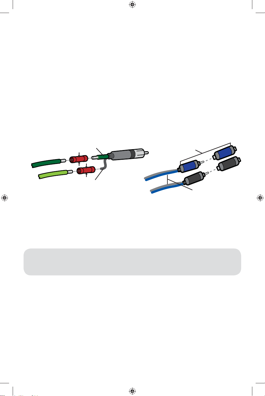
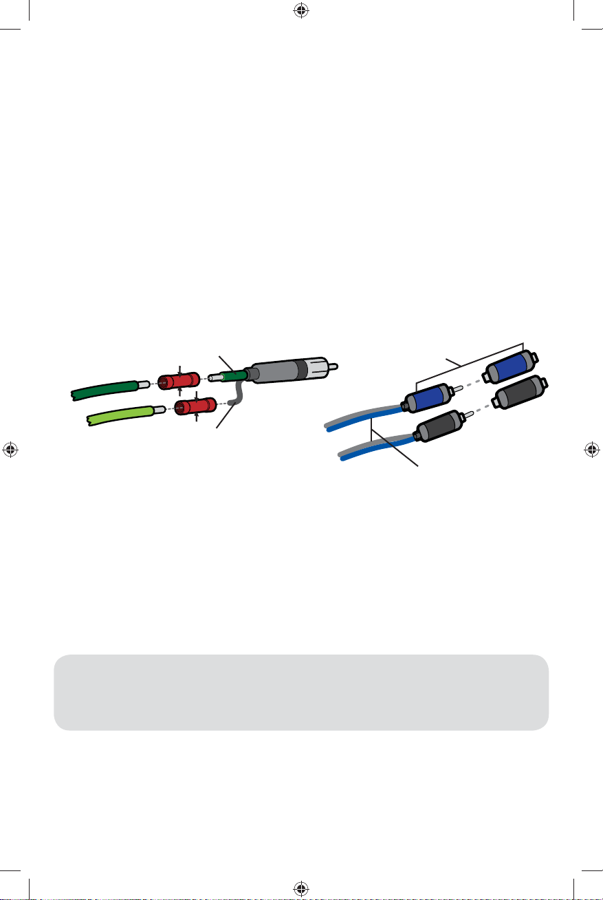
Wiring: The KXM amplifi er has dual input sensitivity differential RCA inputs which will receive either high or low
level signals from your source unit. A high-level signal can be run from the source unit’s speaker outputs to the
stereo RCA input on the end panel of the amplifi er using the KICKER KISL as shown (make sure you set the KXM
amplifi er’s input level switch to “HI”). Alternatively, the signal can be delivered to the amplifi er using the low-level
RCA outputs on the source unit. Set the input level switch on the end panel of the amplifi er to “LO”. Either input
method will provide a low-level output signal at the amplifi er’s RCA output, which effectively passes the audio
signal to another amplifi er or component. Keep the audio signal cable away from factory wiring harnesses and
other power wiring. If you need to cross this wiring, cross it at a 90 degree angle.
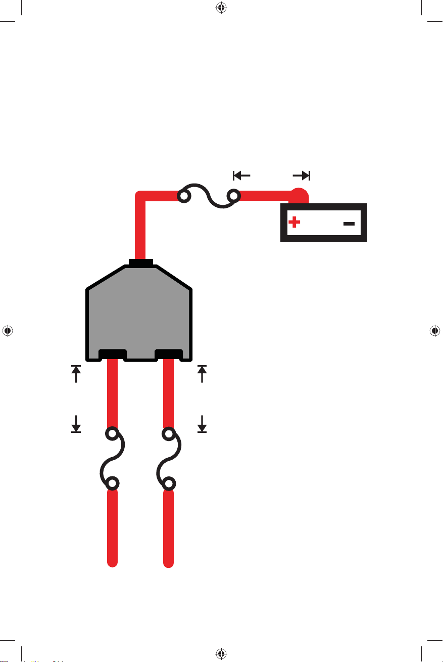
Disconnect the ground wire from the vehicle’s battery to avoid an electrical short. Install a fuse within 7” (18cm) of
the battery and in-line with the power cable connected to your amplifi er. Connect the ground wire to the amplifi er,
then connect this wire to the negative battery terminal. If you ever need to remove the amplifi er from the vehicle
after it has been installed, the ground wire should be the fi rst wire disconnected from the amplifi er.
Model External Fuse (sold separately) Power/Ground Wire
KXM400.4 1 x 60 Ampere 4 Gauge
source unit
high-level speaker
outputs
to amplifi er
shield
+
–
core conductor
KICKER KISL (optional)
from source unit high-
level speaker outputs
OR
to amplifi er
2013 KXM 400.4 Rev E.indd 32013 KXM 400.4 Rev E.indd 3 2/19/2013 3:23:00 PM2/19/2013 3:23:00 PM
4
For multiple amplifi er installations where distribution blocks are used, each amplifi er should have its proper-rated
fuse, or breaker, installed between the amplifi er and the distribution block within seven inches of the block, or on
the distribution block if it provides for fusing. The primary power wire should also be fused between the battery
and distribution block, within seven inches of the battery’s B+ terminal, with a fuse or breaker rated at least to the
sum of the individual amplifi er’s fuse values, but not to exceed 1.5-times the sum of the individual fuse values
(not to exceed the ampacity of the thermal insulation of the wiring as shown in U.S.C.G. CFR33 183.425, Table
5). See the diagram below.
NOTE: Seven inches is the standard distance under U.S. Coast Guard CFR33 for placement of fuses or
breakers as required by law for new boat manufacturing. We recommend trying to adhere to this standard in a
consumer installation. Failure to do so does not mean you are breaking the law, but it does put the safety of your
boat and passengers at risk in the event of a power wire short circuit.
12V
external fuse
to amplifi er to amplifi er
7”
(18cm)
external fuse
7”
(18cm)
external fuse
power distribution block
battery
7”
(18cm)
2013 KXM 400.4 Rev E.indd 42013 KXM 400.4 Rev E.indd 4 2/19/2013 3:23:01 PM2/19/2013 3:23:01 PM
5
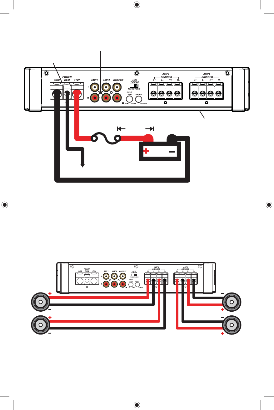
FOUR CHANNEL OPERATION
minimum impedance of 2 ohms per channel
POWER WIRING
12V
battery
external fuse
remote turn-on (see page 7)
L
L
R
R
audio inputs
7”
(18cm)
ABYC-compliant power terminals
Amplifi er uses 304-stainless steel screws
and conformal coated PCB for increased
weather resistance
aluminum bottom plate
2013 KXM 400.4 Rev E.indd 52013 KXM 400.4 Rev E.indd 5 2/19/2013 3:23:02 PM2/19/2013 3:23:02 PM
6
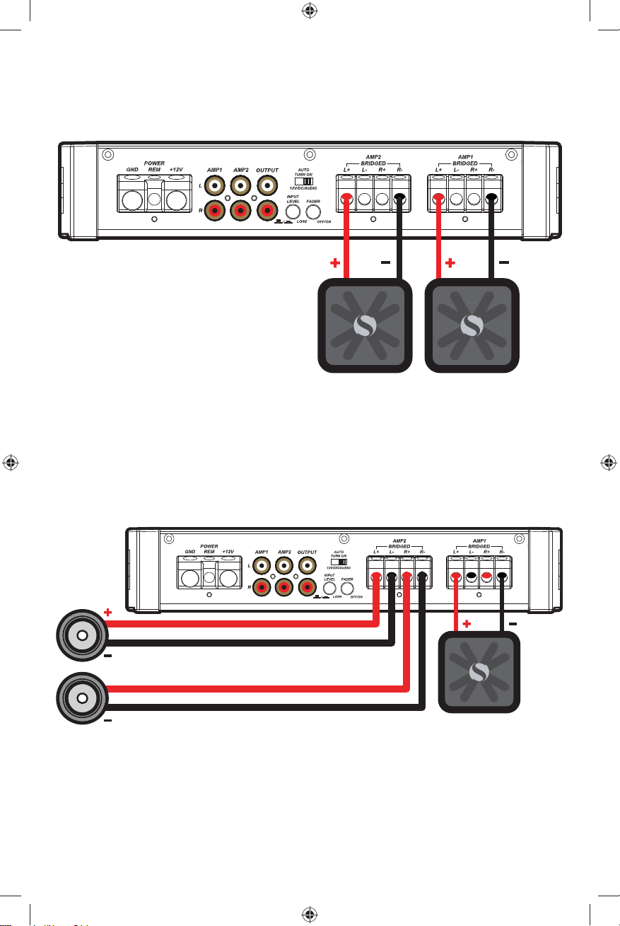
BRIDGED OPERATION (MONO)
minimum impedance of 4 ohms
STEREO-AND-MONO-SIMULTANEOUSLY (SAMS) OPERATION
minimum impedance of 4 ohms bridged (mono) and 2 ohms per channel stereo
L
R
2013 KXM 400.4 Rev E.indd 62013 KXM 400.4 Rev E.indd 6 2/19/2013 3:23:03 PM2/19/2013 3:23:03 PM
7
OPERATION
M4
Automatic Turn-On Selection: The KX series offers three different automatic turn-on modes that can be
selected on the end panel; +12V, DC Offset, and Audio. Using either the DC Offset or Audio mode causes the
REM terminal to have +12V out for turning on additional amplifi ers.
• Remote Turn-On: Set the switch to +12V to use the remote turn-on lead from your source unit. Run 18
gauge wire from the Remote Turn-On Lead on your source unit to the terminal labeled REM between the
amplifi er’s positive and negative power terminals. This is the preferred automatic turn-on method.
• DC Offset Turn-On: If Remote Turn-On is not an option, the next best setting is DC Offset. The DC Offset
mode detects a 6V DC offset from the HI-Level speaker outputs when the source unit has been turned on.
• Signal Sense Turn-On: The Audio setting is the fi nal alternative for Automatic turn-on. This is a Signal Sense
turn-on method that detects the incoming audio signal from your source unit and automatically turns on the
amp. This turn-on method will not work properly if the input gain control is not set appropriately.
Input Level: The RCA inputs on KICKER KX amplifi ers are capable of receiving either Hi or Low-level signals
from your source unit. If the only output available from your source unit is a Hi-Level signal, simply press in the
Input Level switch on the amplifi er. Either input method will provide a low-level output signal at the RCA output,
which effectively passes the audio signal to another amplifi er or component. Refer to the wiring section of this
manual for additional instructions.
Input Gain Control: The input gain control is not a volume control. It matches the output of the source unit to
the input level of the amplifi er. Turn the source unit up to about 3/4 volume (if the source unit goes to 30, turn it
to 25). Next, slowly turn (clockwise) the gain on the amplifi er up until you can hear audible distortion, then turn it
down a little.
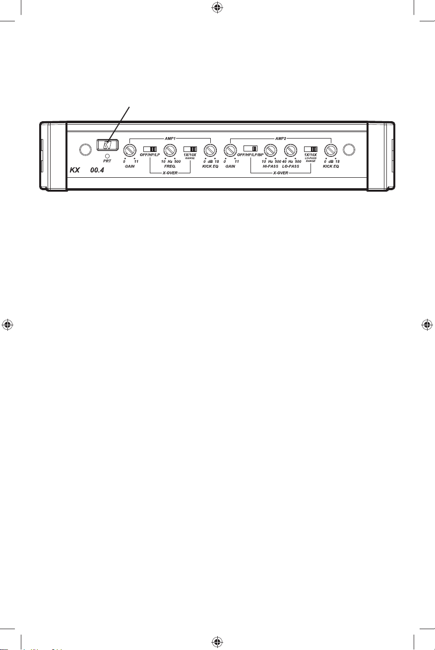
Crossover Switches with Frequency Multiplier: Use the XOVER switches on the end panel of the amplifi er
to set the internal crossovers of AMPS 1 & 2 to OFF, HI-PASS, LO-PASS, or BAND-PASS (AMP 2 only). When
the switch is set to OFF, a full bandwidth signal will be amplifi ed. Set the switch to HP if you want the amplifi er’s
internal crossover to serve as a high-pass fi lter. Set the switch to LP if you want the amplifi er’s internal crossover
to serve as a low-pass fi lter. Set the switch to BP when a specifi c frequency range is required. Never change the
crossover switches with the audio system on!
Set the 1X/10X frequency multiplier switch to the setting that is appropriate for your application. A setting of
10X will set the range of the AMP 1 crossover to 100–5,000Hz, and the LO-PASS crossover of AMP 2 to
400–5,000Hz.
KICK EQ Bass Boost Control: The variable bass boost control on the side of the KXM400.4 amplifi er is
designed to give you increased output, 0–18dB, at 40Hz. The setting for this control is subjective. If you turn it
up, you must readjust the input gain control to avoid clipping the amplifi er.
Mini-USB for internal use only; do NOT remove or tamper. KICKER is not responsible for any
damage to equipment resulting from connections made to this port.
Use a 3mm hex key to remove side panel cover
2013 KXM 400.4 Rev E.indd 72013 KXM 400.4 Rev E.indd 7 2/19/2013 3:23:04 PM2/19/2013 3:23:04 PM

8
TROUBLESHOOTING
If your amplifi er does not appear to be working, check the obvious things fi rst such as blown fuses, poor or
incorrect wiring connections, incorrect setting of crossover switch and gain controls, etc. There is a Protection
(PRT) LED on the side panel of your KICKER KXM series amplifi er. Depending on the state of the amplifi er and
the vehicle’s charging system, the LED will either glow red or be off.
Red (PRT) LED fl ickering with loud music? The red (PRT) LED indicates low battery voltage or an illegal
load. Check all the connections in your vehicle’s charging system. It may be necessary to replace or charge your
vehicle’s battery or replace your vehicle’s alternator.
Red (PRT) LED on, no output?
Amplifi er is very hot = thermal protection is engaged. Test for proper
impedance at the speaker terminals with a VOM meter (see the diagrams in this manual for minimum
recommended impedance and multiple speaker wiring suggestions). Also check for adequate airfl ow around
the amplifi er.
Amplifi er shuts down only while vehicle is running = voltage protection circuitry is engaged.
Voltage to the amplifi er is not within the 10–16 volt operating range. Have the vehicle’s charging and electrical
system inspected.
Amplifi er will only play at low volume levels = short circuit protection is engaged. Check
for speaker wires shorted to each other or to the vehicle chassis. Check for damaged speakers or speaker(s)
operating below the minimum recommended impedance.
No or low output?
Check the balance control on source unit
Check the RCA (or speaker input) and
speaker output connections.
Make certain that the amplifi er is not in BP (Band-pass) mode and that you have
created a notch fi lter.
Alternator noise-whining sound with engine’s RPM?
Check for damaged RCA (or speaker input) cable
Check the routing of RCA (or speaker input) cable
Check the source unit for proper grounding
Check
the gain settings and turn them down if they are set too high.
Ground Noise? On a boat or other watercraft, alternator noise or ground loop noise is usually a voltage potential
difference, and it can happen on either the positive or the ground side of the power wiring. The most common
issue is that the stereo system wiring is delivered from two different locations and is therefore at two different
voltage potentials. The head unit power usually comes from the helm’s wiring harness, while the amplifi er’s power
comes straight from the battery. The helm wiring has lots of noise on it from tachometers (the most common
engine noise culprit), depth fi nders, and engine management computers. The helm ground cable is often too
small for its total load. As a result, both the positive and the ground are usually at different voltage potentials
compared to amplifi er power wiring.
The easiest way to get rid of noise is to ensure that the head unit’s positive and ground wire are at exactly the
same voltage potential as the amplifi er(s). The easiest way to accomplish this is to have the head unit’s power
wiring removed from the helm’s power harness, moving it directly to the battery or the amplifi er’s power terminals,
with the positive wire running through a switch or switched relay to allow the system to be turned on or off.
CAUTION: When jump starting the vehicle, be sure that connections made with jumper cables are correct.
Improper connections can result in blown amplifi er fuses as well as the failure of other critical systems in the
vehicle.
If you have more questions about the installation or operation of your new KICKER product, see the Authorized
KICKER Dealer where you made your purchase. For more advice on installation, click on the SUPPORT tab on
the KICKER homepage, www.kicker.com. Choose the TECHNICAL SUPPORT tab, choose the subject you are
interested in, and then download or view the corresponding information. Please E-mail support@kicker.com or
call Technical Services (405) 624-8583 for unanswered or specifi c questions.
2013 KXM 400.4 Rev E.indd 82013 KXM 400.4 Rev E.indd 8 2/19/2013 3:23:04 PM2/19/2013 3:23:04 PM

9
KICKER will now provide a
three-year warranty with all KXM-
Series Amplifi er purchases paired
with qualifying KICKER Installation
Accessories.
This extends the standard warranty by an additional year.
Amplifi er must be purchased from an
Authorized KICKER Dealer.
KICKER KXM amplifi er success is currently at an unheard-of rate, making the extended
warranty program even more benefi cial to you.
Using poor-quality, under-spec wiring will impede KXM amplifi er performance.
A superior-quality installation is guaranteed to extend the life of KXM amplifi ers.
The new extended warranty applies only to KICKER amplifi ers and accessories sold to consumers by Authorized
KICKER Dealers in the United States of America or its possessions. It also only applies to the original purchaser of
KICKER amplifi ers and accessories. One warranty extension per amplifi er is allowed. This program does not apply to “B”-
stock product or factory-refurbished product.
This offer is for a limited time, so see your local Authorized KICKER Dealer soon for details.
*U.S.A. Only | EE.UU. solamente | Nur USA | Les USA Seulement
KXM400.4
50W x 4 @ 4 ohms, 14.4VDC, 1% THD, CEA-2006B (Watts)
Signal to Noise Ratio -75dB CEA-2006B (ref: 1W, A-weighted)
2013 KXM 400.4 Rev E.indd 92013 KXM 400.4 Rev E.indd 9 2/19/2013 3:23:04 PM2/19/2013 3:23:04 PM

10
AMPLIFICADOR DE LA SERIE KXM.4
MANUAL DEL PROPIETARIO
INSTALACIÓN
Montaje: Elija una ubicación seca y en buenas condiciones estructurales para montar su amplifi cador KICKER.
Asegúrese de que no exista ningún elemento detrás del área donde se van a colocar los tornillos. Elija una
ubicación que permita al menos 4” (10 cm) de ventilación abierta para el amplifi cador. Taladre cuatro orifi cios
utilizando una broca de 7/64” (3 mm) y utilice los tornillos N.º 8 suministrados para montar el amplifi cador.
RENDIMIENTO
Distribuidor autorizado de KICKER:
Fecha de compra:
Número de serie del amplifi cador:
Modelo: KXM400.4
Potencia RMS
@ 14.4V, 4 estéreofónico, 1% THD+N
@ 14.4V, 2 estéreofónico, 1% THD+N
@ 14.4V, 4 puente, 1% THD+N
50W x 4
100W x 4
200W x 2
Largo | in. [cm] 11 3/16 [28.4]
Altura | in. [cm] 2 3/16 [5.5]
Ancho | in [cm] 8 5/16 [21]
Respuesta de frecuencias ± 1dB 10Hz–20KHz
Relación de señal a ruido >95dB, ponderado en A, ref: potencia nominal
Sensibilidad de entrada Baja Nivel: 125mV–5V
Alto Nivel: 250mV–10V
Separador de frecuencia electrónico Amp 1: Off/Paso alto/Paso bajo Variable 10–5,000Hz
con 10X interr.;
Amp 2: Off/PA/PB/PB Variable PA, 10–500Hz; Variable
de paso bajo, 40–5,000Hz con 10X interr.
Pendiente: 24dB/octava
Refuerzo de Bajos KICK EQ 0–18dB @ 40Hz variable
Nota: Para obtener el mejor rendimiento de sus nuevos amplifi cadores KICKER, le recomendamos que use
accesorios y cableado KICKER auténticos.
MODELO: KXM400.4
2013 KXM 400.4 Rev E.indd 102013 KXM 400.4 Rev E.indd 10 2/19/2013 3:23:05 PM2/19/2013 3:23:05 PM
11
Modelo Fusible Externo
(no incluido)
Cable de Alimentación
y Conexión a Tierra
KXM400.4 1 x 60 Ampere Calibre 4
Cableado: Desconecte la batería del vehículo para evitar un cortocircuito eléctrico. El amplifi cador KXM posee
entradas RCA diferenciales de doble sensibilidad que recibirán señales de alto o bajo nivel desde su fuente de
energía. Una señal de alto nivel puede emitirse desde las salidas del parlante de la fuente de energía a la entrada
RCA del estéreo en el panel lateral del amplifi cador utilizando el KICKER KISL como se muestra (asegúrese de
ajustar el interruptor de nivel de entrada del amplifi cador en “HI”). Como alternativa, la señal se puede emitir al
amplifi cador utilizando las salidas RCA de bajo nivel en la fuente de energía. Ajuste el interruptor de nivel de
entrada en el panel lateral del amplifi cador en “LO”. Cualquier método de entrada emitirá una señal de salida
de bajo nivel en la salida RCA, la cual pasará la señal de audio a otro amplifi cador o componente. Mantenga el
cable de señal de audio lejos de arneses de conexión de fábrica y de otros cables eléctricos. En caso de que
necesite cruzar este cableado, hágalo a un ángulo de 90 grados desde las salidas del parlante de alto nivel de
la fuente de energía
Instale un fusible a 7” (18 cm) de la batería y en línea con el cable de alimentación conectado a su amplifi cador.
Conecte el conductor de tierra al amplifi cador, luego conéctelo al terminal negativo de la batería. Si alguna vez
necesita retirar el amplifi cador del vehículo luego de haberse instalado, el conductor de tierra debe ser el último
cable que se desconecte del amplifi cador: simplemente lo opuesto a lo que hizo cuando lo instaló.
Cable de salida
de altavoz de
alto nivel
Hacia el amplifi cador
Hacia el
amplifi cador
Conexión a tierra o blindaje
+
–
cable central
KICKER KISL
Cable de salida de
altavoz de alto nivel
O
2013 KXM 400.4 Rev E.indd 112013 KXM 400.4 Rev E.indd 11 2/19/2013 3:23:05 PM2/19/2013 3:23:05 PM
 Loading...