


KX75.2
Table of contents
 Loading...
KX75.2
Congratulations! You have just purchased the latest in amplifier technology to carry the famous KICKER name. Your KICKER KX series
amplifier is designed and built to give you years of powerful and trouble-free performance. This installation manual contains valuable information on how to get the most out of your new KX series amplifier.
Thanks for buying KICKER. Enjoy!
KX Amplifier Features
Low Impedance Operation Stable into 2 ohm stereo or 4 ohm mono
loads.
SORT Protection Circuitry (Short circuit, Over-voltage, Reverse polarity,
Thermal) Protects amplifier from accidents and undesired operation.
MOSFET Power Supply Provides high efficiency operation.
KickBass Variable bass boost circuit which provides up to 12 dB of boost at 40
Hz.
Built-In Crossover 12 dB High pass or Low pass fixed at 80Hz. Defeatable for
full range operation.
High & Low level inputs Allows connection to various sources such as:
aftermarket stereos, factory radios, DVD players, Video Cassette Player, etc.
Custom tooled gold plated connectors Assure maximum power transfer
and damping.
SAMS (Stereo And Mono Simultaneously) Amplifier will operate into a bridged
mono load and a stereo load at the same time.
Two Year Warranty When installed by Authorized KICKER dealer.
Mounting Instructions
When selecting a location to mount your Kicker amplifier be sure it is structurally sound and that there are no items behind the area that could be damaged by the screws. Check for wiring, brake lines, fuel lines, gas tanks, etc.
All amplifiers generate heat under normal operation. Be sure to choose a location that allows adequate ventilation for the amplifier. Also consider that the air
temperature inside an automobile’s trunk can reach upwards of 140 degrees
fahrenheit. An amplifier mounted here may require additional cooling needs
such as fans or venting to allow cool operation. If possible, mounting the amp in
the passenger compartment will allow cooler operation.
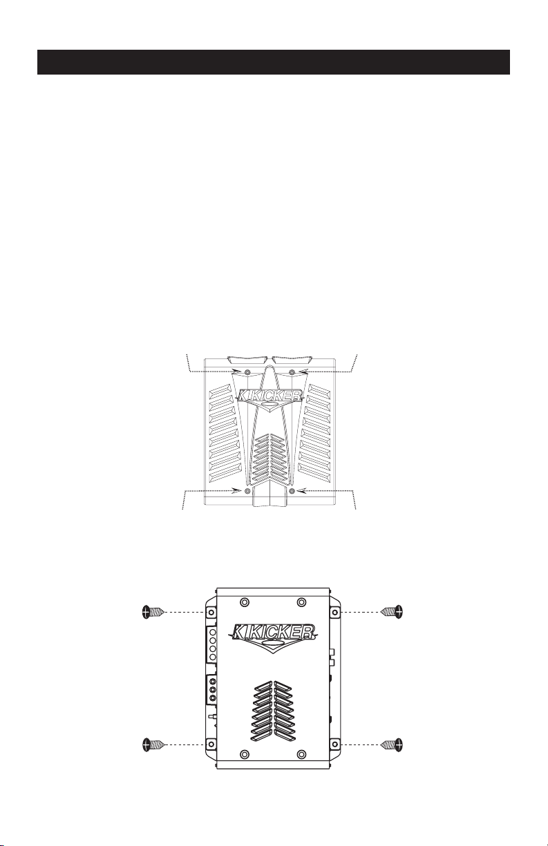
Now that you are ready to mount your amplifier, use the supplied 3mm allen
wrench to remove the amplifier shroud. This will give you access to the mounting holes in the amplifier and all wiring connections.
Remove
Remove
Remove
Remove
With the shroud removed, you now have access to the four mounting holes in
the mounting feet and all wiring connections. Drill 4 holes using a 7/64” drill bit
and use the supplied #8 screws to mount the amplifier.
2
Wiring Instructions
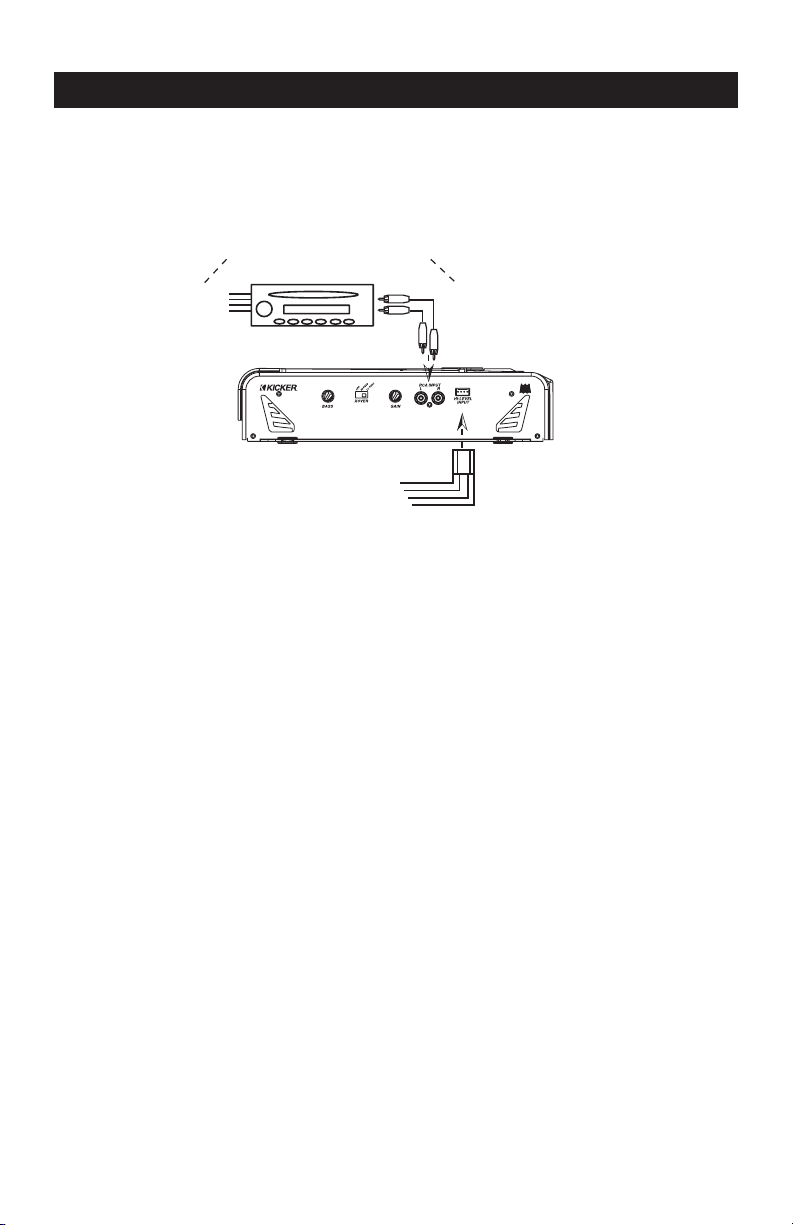
Signal can be input into the amplifier using either the low level RCA input connections or the high level (speaker level) connections. Using the low level RCA
connections is the preferred method. Use the high level inputs only if your head
unit does not have low level RCA type outputs.
WARNING-Use Only One...
Never Both At The Same Time!!!
Speaker
Outputs
SOURCE UNIT
High-Level
Inputs
RIGHT +
RIGHT -
LEFT -
LEFT +
RCA
Outputs
The use of twisted pair interconnects is recommended for all installations to
minimize noise. When routing these cables through the automobile, try to keep
them away from factory wiring harnesses and other power wiring. If you need to
cross any of this wiring do so at a 90 degree angle to reduce the possibility for
noise problems.
When working with power connections it is always recommended that you disconnect the battery to prevent accidents.
The ground should be connected to the amplifier first before making any of
the other connections. This wire should be as short as possible (24 inches or less)
and connected to a paint/corrosion free solid metal area of the car’s chassis. Use
the same gauge wire as recommended for the amplifiers power connection to
the battery. Adding an additional ground wire between the car battery’s negative
post and the car chassis of this same gauge (or larger) is also recommended.
If you ever need to remove the amp from the vehicle after it has been
installed, the ground wire should be the last wire disconnected from the amplifier, just the opposite as when you installed it.
A fuse must be installed within 18 inches of the battery to protect the power
wire feeding your amplifier. This fuse should be of at least the same value used
in the amplifier but no higher than the capacity of the wire. See the chart below
for wire size and fusing recommendations.
Model Fuse Size Wire Size
KX75.2 15A 8GA
3
Loading...