


KSS50

KS COMPONENT SPEAKERS
KSS50 | KSS650 | KSS670
Owner’s Manual | English
Manual del Propietario | Español
Altavoz Componentes KS
Benutzerhandbuch | Deutsch
KS Komponenten-System
Manuel d’utilisation | Française
Haut-parleurs Composants KS
KSS
Speakers
2017 KS Component Rev B.indd 12017 KS Component Rev B.indd 1 8/23/2016 12:22:38 PM8/23/2016 12:22:38 PM

2
KS COMPONENT SYSTEM
Owner’s Manual
MODELS: KSS50 | KSS650 | KSS670
PERFORMANCE
KS COMPONENT SPEAKERS
The KICKER KS speakers offer an excellent upgrade to your vehicle’s factory sound system, delivering great
full-range sound at an amazing value! Whether dropping the KS speakers in a factory location or customizing
your install, their high-effi ciency design means less power is needed to play your music, while our use of
advanced materials and construction techniques ensures optimal performance for years to come.
IMPORTANT SAFETY WARNING
Prolonged continuous operation of an amplifi er, speaker, or subwoofer in a distorted, clipped or over-
powered manner can cause your audio system to overheat, possibly catching fi re and resulting in serious
damage to your components and/or vehicle. Amplifi ers require up to 4 inches (10cm) open ventilation.
Subwoofers should be mounted with at least 1 inch (2.5cm) clearance between the front of the speaker and
any surface.
KS Component Speakers KSS50 KSS650 KSS670
Woofer [in, mm] 5-1/4, 130 6-1/2, 160 6-3/4, 165
Tweeter [in, mm] 1, 25 1, 25 1, 25
Dome Material Silk Silk Silk
Rated Impedance [Ω] 4 4 4
Peak Power Handling [ Watts] 200 250 250
Continuous Power Handling [Watts RMS] 100 125 125
Sensitivity [1W, 1m] 88 90 91
Frequency Response [Hz] 38-21k 35-21k 35-21k
Woofer Mounting Hole Diameter [in, mm] 4-1/2, 115 4-13/16, 123 5-9/16, 141
Woofer Top Mount Depth [in, mm] 1-3/4, 45 1-13/16, 46 1-13/16, 46
Flush Mount Tweeter Hole Diameter [in, mm] 1-3/4, 45 1-3/4, 45 1-3/4, 45
Flush Mount Tweeter Depth [in, mm] 11/16, 17 11/16, 17 11/16, 17
High Pass [dB], at Frequency [Hz] 12, 4,000 12, 4,000 12, 4,000
Low Pass [dB], at Frequency [Hz] 12, 4,000 12, 4,000 12, 4,000
High Frequency Output Attenuation [dB] 0, 4.5, 9 0, 4.5, 9 0, 4.5, 9
Note: All specifi cations and performance fi gures are subject to change. Please visit www.kicker.com for the
most current information. To get the best performance from your new KICKER speakers, we recommend using
genuine KICKER accessories and wiring. Please allow two weeks of break-in time for the speakers to reach optimum
performance.
Pro Tip: You’re a KICKER amplifi er and a few cables away from a full system upgrade that will dominate
any factory system! KICKER line of amplifi ers make it easy to upgrade to solid bass with your existing or
stock source unit. Also, ask your dealer about KICKER Subwoofer upgrades.
2017 KS Component Rev B.indd 22017 KS Component Rev B.indd 2 8/23/2016 12:22:40 PM8/23/2016 12:22:40 PM
3
CONFIGURATION
Before mounting and wiring the KS component system, determine which confi guration you will use for the
speakers.
KS Speaker
Confi gurations
ADVANTAGES CONSIDERATIONS
Coaxial great for space-limited applications
or when separate tweeter mounting
is not possible
high frequencies may not be as
prominent | tweeter output may
need to be increased at crossover
Separates optimal sound quality and improved
sonic imaging (with proper tweeter
mounting)
trickier install | vehicle must have a
good tweeter mounting location
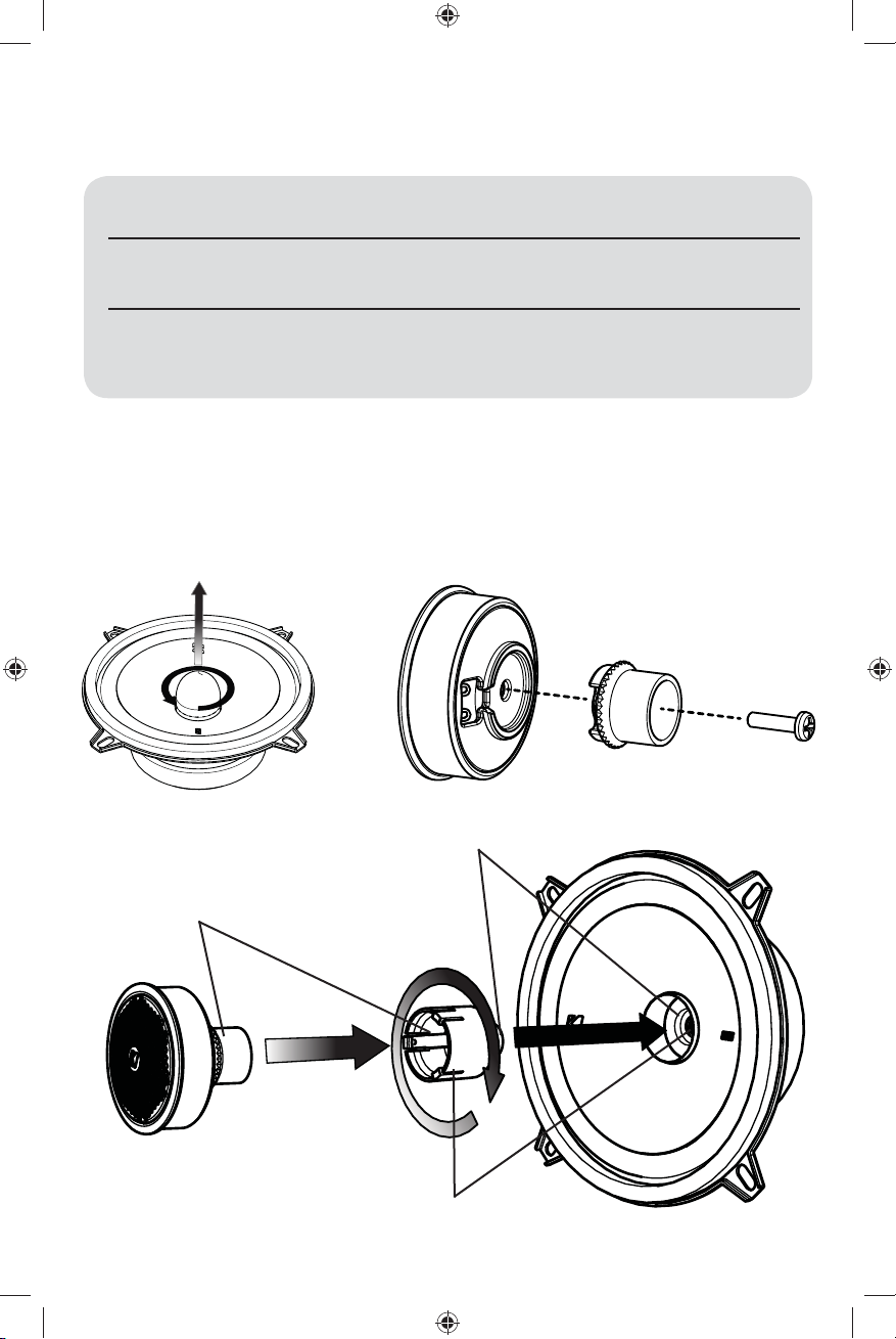
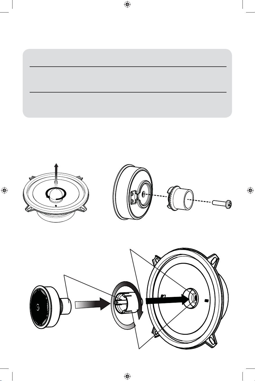
2.
5.
1.
4.
remove phase plug
screw tweeter post to speaker
Attach tweeter back to tweeter
snap tweeter to tweeter post
thread tweeter wire through post and speaker
Coaxial Confi guration
3.
The KS speakers come in a separates confi guration. For coaxial operation, use the following steps to
attach the tweeter.
2017 KS Component Rev B.indd 32017 KS Component Rev B.indd 3 8/23/2016 12:22:40 PM8/23/2016 12:22:40 PM
4
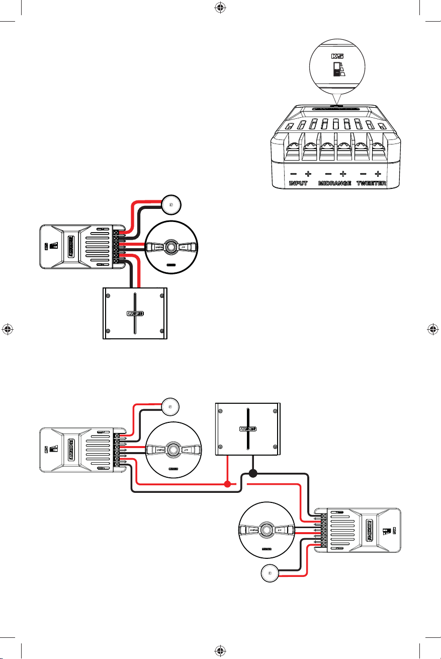
CROSSOVER & WIRING CONFIGURATION
We recommend using 16 gauge (or larger) wire. The KS Speakers
are rated at 4 ohms and work with any source unit or amplifi er
designed to operate at a 4 ohm load. Make sure your source
unit or amplifi er is rated for 4 ohm operation.
Use the tweeter attenuation switch to adjust the output level of
the tweeter to 0 dB, +4.5 dB, or +9 dB.
Higher switch settings will
result in more volume from the tweeter.
+-
+
+
-
-
+
-
+
+
+
-
-
-
+
+
+
-
-
-
crossover
Crossover Wiring
Two component sets per channel
Crossover Wiring
One component set per channel
source unit / amplifi er
At least two amplifi er channels are needed for
stereo operation (only one channel is shown)
Requires two complete KS systems
(four woofers, four tweeters, four crossovers)
At least two amplifi er channels
are needed for stereo operation
(only one channel is shown)
Crossovers wired in parallel. Make sure your source
unit or amplifi er is rated for 2 ohm operation.
2017 KS Component Rev B.indd 42017 KS Component Rev B.indd 4 8/23/2016 12:22:40 PM8/23/2016 12:22:40 PM
5
door jamb
KS crossover. (mounted
inside door panel)
rubber grommets from amplifi er or
source unit
woofer mounting hole
tweeter mounting hole
to woofer terminals
to tweeter lead wires
CROSSOVER MOUNTING
Mount the crossover in a location that is easy to access for wiring and tweeter output level adjustment.
Make sure that the crossover will not be exposed to water. The bottom of the car door is not a good
location. If you must mount the crossover in the car door, exercise caution as water can accumulate in the
bottom of the door. Keep the crossover high in the door and shielded from water.
If factory speaker wiring is not available in your desired location, it may be necessary to run speaker wire
through the door jamb. The speaker wire should be kept away from sharp edges and avoid the possibility of
getting pinched by the door. An existing grommet in the door jamb is the ideal place to run the speaker wire.
If the factory hole and grommet do not exist or are inaccessible, you must drill a hole to run the speaker wire
through the door jamb. Be careful not to drill into other wiring or existing door mechanisms. Any time a wire
is run through a hole, it is necessary to insert a rubber or plastic grommet to protect the wire from damage.
2017 KS Component Rev B.indd 52017 KS Component Rev B.indd 5 8/23/2016 12:22:40 PM8/23/2016 12:22:40 PM

6
door
door panel
speaker cut-out
KS speaker
SPEAKER MOUNTING
The KICKER KS Speakers are designed for free-air applications and do not require a sealed enclosure for
optimum performance. It is important to isolate the sound coming from the front of the speaker from the
sound radiating from the back of the speaker. This is most easily accomplished by mounting the speakers
in a vehicle’s factory locations or in a location with a semi-isolated rear chamber (like the rear deck of a car
behind the rear seats).
If you are replacing factory speakers in their original locations, you may have to enlarge the speaker cut-
outs and pre-drill new screw holes using a 7/64” (2.5mm) bit. Custom mounting locations will require more
preparation and work. Make sure that the speaker will not interfere with trunk and door opening and closing
mechanisms and that the enclosed screws will not puncture the fuel tank, puncture wiring, or interfere with
any other mechanical parts on the underside of the mounting surface. Cycle the windows all the way down
and up.
If the speaker cut-out locations require you to cut metal, avoid structural metal and braces. If the door body
and panel cannot support the weight of the speaker, an optional reinforcing ring (thin piece of wood or
Medium Density Fiberboard) may be fastened or adhered to the door body.
2017 KS Component Rev B.indd 62017 KS Component Rev B.indd 6 8/23/2016 12:22:40 PM8/23/2016 12:22:40 PM
7
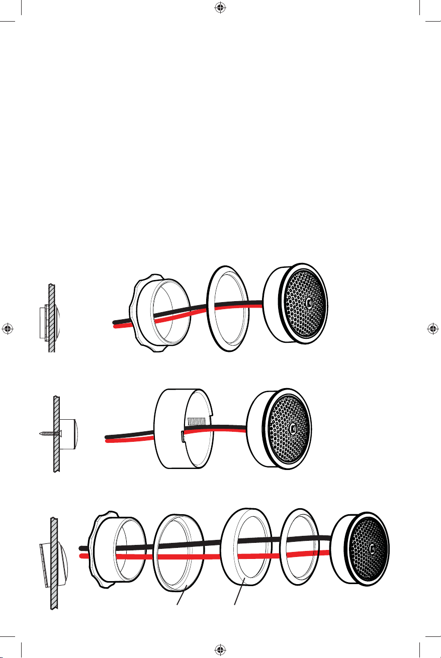
TWEETER MOUNTING
The tweeter can be separately mounted one of three ways: fl ush, angled and surface. For fl ush mounting
applications, choose a fl at location on the panel with space behind the panel to allow room for the short
mounting nut, motor structure, and tweeter. After checking the clearances, cut a 1-3/4” (44mm) diameter
mounting hole in the panel. Position the short mounting nut behind the panel. Feed the wire through the
optional fl ush ring, the hole in the panel, and the mounting nut. Mount the tweeter by screwing the mounting
nut onto the tweeter.
For surface mounting applications use the surface mount cup as a template and pre-drill one 7/64” (2.5mm)
screw hole (using two holes is optional) for attaching the surface mount cup to the panel and a 5/16” (8mm)
hole for the wires. An M3 pan-cross head wood screw is supplied to attach the surface mount cup to the
panel. Position the tweeter over the surface mount cup and screw it into position.
For angled mounting applications choose a fl at location on the panel with space behind the panel to allow
room for the long mounting nut, motor structure, tweeter post, and back angle ring. After checking the
clearances, cut a 1-3/4” (44mm) diameter mounting hole in the panel. Place the front angle ring in front of
the panel. Then place the wire and tweeter through the front angle ring and into the panel. Next, place the
wire through the back angle ring, place the back angle ring over the rear of the tweeter, and line-up the
narrow part of the front angle ring for the preferred angle of operation. Place the wire through the mounting
nut and loosely tighten the mounting nut around the tweeter. Rotate all the parts in unison until the tweeter is
angled in the desired direction. Secure the assembly by tightening the mounting nut.
panel
panel
panel
short mounting nut
fl ush ring
tweeter
tweeter
tweeter
surface mount cup
Flush Mounting
Angle Mounting
Surface Mounting
fl ush ring
long mounting nut
back angle ring
decrease mounting depth by
removing tweeter back cover
front angle ring
rounded surface
inset surface
2017 KS Component Rev B.indd 72017 KS Component Rev B.indd 7 8/23/2016 12:22:44 PM8/23/2016 12:22:44 PM

8
Manual del propietario del
SISTEMA DE COMPONENTES KS
COMPONENTES KS
Los sistemas de Component de la serie KS de KICKER ofrecen una fi delidad de audio inigualable para
aplicaciones para vehículos. Ya sea para confi gurar el último sistema de sonido envolvente con altavoces
múltiples y subwoofer o simplemente para mejorar la versión de parlantes aburridos y sin vida de fábrica,
los sistemas de Componentes KS brindan el sonido de gama completa más placentero del mercado en la
actualidad!
RENDIMIENTO
MODELO: KSS50 | KSS650 | KSS670
Altavoz Componentes KS KSS5 KSS65 KSS67
Parlante Baja Frecuencia (Woofer) [pulgada, mm] 5-1/4, 130 6-1/2, 160 6-3/4, 165
Parlante Alta Frecuencia (Tweeter) [pulgada, mm] 1, 25 1, 25 1, 25
Material para la cúpula Seda Seda Seda
Impedancia nominal [Ω] 4 4 4
Manejo de la potencia máxima [Watts] 200 250 250
Manejo de la corriente continua [Watts RMS] 100 125 125
Sensibilidad [1W, 1m]
88 90 91
Respuesta en frecuencia [Hz] 38-21k 35-21k 35-21k
Diámetro del orifi cio de montaje woofer [pulgadas, mm] 4-1/2, 115 4-13/16, 123 5-9/16, 141
Profundidad del montaje del woofer [pulgadas, mm] 1-3/4, 45 1-13/16, 46 1-13/16, 46
Diámetro del orifi cio del montaje empotrado del tweeter [pulgadas, mm] 1-3/4, 45 1-3/4, 45 1-3/4, 45
Profundidad del montaje empotrado del tweeter [pulgadas, mm] 11/16, 17 11/16, 17 11/16, 17
Paso alto [dB] frecuencia de [Hz] 12, 4,000 12, 4,000 12, 4,000
Paso bajo [dB] frecuencia de [Hz] 12, 4,000 12, 4,000 12, 4,000
Atenuación de la salida de alta frecuencia [dB] 0, 4.5, 9 0, 4.5, 9 0, 4.5, 9
IMPORTANTE ADVERTENCIA DE SEGURIDAD
Funcionamiento continuo prolongado de un amplifi cador, altavoz o subwoofer de una manera distorsionada,
recortado o el exceso de potencia puede hacer que el sistema de audio se sobrecaliente, posiblemente
la captura de fuego y que resulta en graves daños a sus componentes y / o vehículo. Amplifi cadores
requieren hasta 4 pulgadas (10 cm) de ventilación abierta. Subwoofers deben montarse con el aclaramiento
(2,5 cm) por lo menos 1 pulgada entre la parte frontal del altavoz y cualquier superfi cie.
Consejo profesional: ¡Usted es un KICKER Amplifi cador, y unos pocos cables lejos de un sistema
fuerte estéreo! KICKER amplifi cadores lo hace fácil de mejorar sólido como una roca bajo con su existir
estéreo. Pregunte por favor su comerciante acerca de los aumentos de Amplifi cador de Kicker.
2017 KS Component Rev B.indd 82017 KS Component Rev B.indd 8 8/23/2016 12:22:44 PM8/23/2016 12:22:44 PM
9
Confi guración coaxial
CONFIGURACIÓN
Antes de montar y realizar el cableado del sistema de componentes KS , determine qué confi guración
utilizará para los altavoces.
Confi guraciones de
los altavoces KS
VENTAJAS CONSIDERACIONES
Coaxial
Excelente para aplicaciones con
espacio limitado o cuando no es posible
el montaje del tweeter por separado
Es posible que las frecuencias altas
no sean tan prominentes | Es posible
que se necesite aumentar la salida
del tweeter en el crossover
Por separado Óptima calidad de sonido y mejor
imagen acústica (con el montaje
adecuado del tweeter)
Instalación más difícil | El vehículo
debe tener una buena ubicación
de montaje del tweeter
2.
5.
1.
4.
3.
El sistema de componentes KS viene empaquetado en una confi guración por separado.
Para utilizar una confi guración coaxial, siga los pasos a continuación:
retire la clavija de fase
atornille el montante del altavoz de alta
frecuencia al altavoz
Adhiera el altavoz de alta frecuencia detrás del altavoz
conecte el altavoz de alta frecuencia
a su montante
pase el cable del altavoz de alta frecuencia a través del montante y altavoz
2017 KS Component Rev B.indd 92017 KS Component Rev B.indd 9 8/23/2016 12:22:45 PM8/23/2016 12:22:45 PM
 Loading...